Embed Size (px)
Citation preview

Combustion & Fuels Research Laboratory
StudentsMr. Kenneth Kroenlein Ms. Lily Zheng
Mr. Peter Strapp (summer) Jeff Stein (summer)
Research Staff and Visiting ResearchersDr. Andrei Kazakov Dr. Marcos ChaosMr. Paul Michniewicz Dr. Zhenwei Zhao
Dr. Boguslaw Gajdeczko (Consultant)
Professor Frederick L. Dryer ([email protected])
(http://www.princeton.edu/~combust)
Areas of InterestChemical Kinetics and Reacting Systems of Conventional & Alternate FuelsMicroscale PropulsionMicrogravity Combustion and Extinction of Isolated DropletsAdvanced Internal Combustion Engine-Related ResearchHydrogen Fuel Economy-Related Research
Chemical Kinetics and Reacting Systems
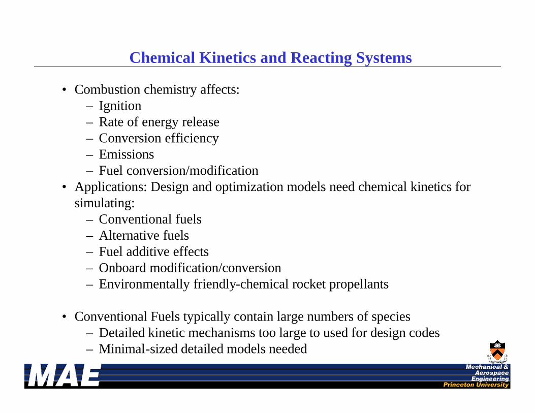
• Combustion chemistry affects:– Ignition– Rate of energy release– Conversion efficiency– Emissions– Fuel conversion/modification
• Applications: Design and optimization models need chemical kinetics for simulating:
– Conventional fuels– Alternative fuels– Fuel additive effects– Onboard modification/conversion– Environmentally friendly-chemical rocket propellants
• Conventional Fuels typically contain large numbers of species– Detailed kinetic mechanisms too large to used for design codes– Minimal-sized detailed models needed

Experimental Techniques
• Variable Pressure Flow Reactor– A variable pressure flow reactor is used to determine the time evolution of reactant,
intermediate, and product species as well as mixture temperature.– A hot-water cooled stainless steel probe continuously samples and convectively
quenches a small percentage of the total flow. Gas temperature is measured with a silica-coated type R thermocouple.
– On-line diagnostic instruments include an electrochemical oxygen analyzer, a hydrogen analyzer, and an FTIR spectrometer for H2O and NOx measurements.
– High flow rates and dilute mixtures (typically 1% fuel) minimize spatial gradients, thereby suppressing diffusion and creating a convective-reactive system.
– The flow reactor approximates isobaric, plug flow operation, with negligible axial diffusion in comparison to convection. These conditions enable zero-dimensional modeling of the reacting system.
• Laminar Pre-mixed Flames– Define unstretched reference SL for pure large hydrocarbon fuels, simple fuel mixtures
and reference gasoline as a function of equivalence ratio, unburned gas temperature, exhaust gas dilution, and pressure for further validation of kinetic mechanisms.
– Investigate the effects of composition, fuel contaminants and additives on sooting phenomena.
Kinetic Mechanisms for DesignDetailed Mechanism Reduction Example: n-Heptane
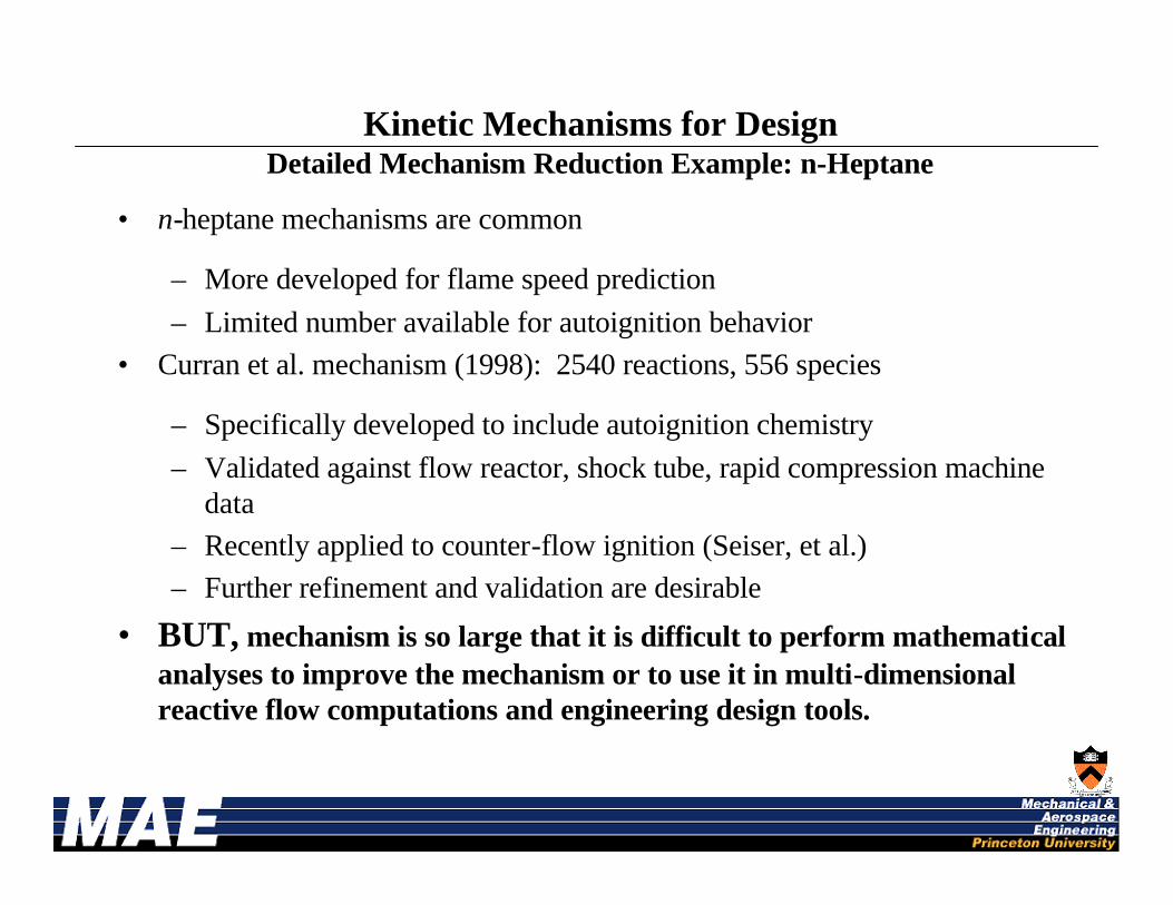
• n-heptane mechanisms are common
– More developed for flame speed prediction
– Limited number available for autoignition behavior• Curran et al. mechanism (1998): 2540 reactions, 556 species
– Specifically developed to include autoignition chemistry
– Validated against flow reactor, shock tube, rapid compression machine data
– Recently applied to counter-flow ignition (Seiser, et al.)– Further refinement and validation are desirable
• BUT, mechanism is so large that it is difficult to perform mathematical analyses to improve the mechanism or to use it in multi-dimensional reactive flow computations and engineering design tools.
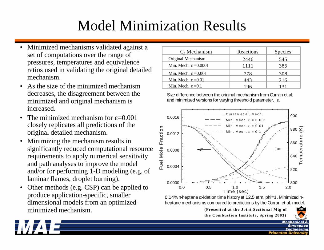
Model Minimization Results• Minimized mechanisms validated against a
set of computations over the range of pressures, temperatures and equivalence ratios used in validating the original detailed mechanism.
• As the size of the minimized mechanism decreases, the disagreement between the minimized and original mechanism is increased.
• The minimized mechanism for ε=0.001 closely replicates all predictions of the original detailed mechanism.
• Minimizing the mechanism results in significantly reduced computational resource requirements to apply numerical sensitivity and path analyses to improve the model and/or for performing 1-D modeling (e.g. of laminar flames, droplet burning).
• Other methods (e.g. CSP) can be applied to produce application-specific, smaller dimensional models from an optimized-minimized mechanism.
0.14% n-heptane oxidation time history at 12.5 atm, phi=1. Minimized n-heptane mechanisms compared to predictions by the Curran et al. model.
Size difference between the original mechanism from Curran et al. and minimized versions for varying threshold parameter, ε.
C7 Mechanism Reactions SpeciesOriginal Mechanism 2446 545Min. Mech. ε =0.0001 1111 385Min. Mech. ε =0.001 778 308Min. Mech. ε =0.01 443 216Min. Mech. ε =0.1 196 131
Time (sec)0.0 0.5 1.0 1.5 2.0
Fu
el
Mo
le F
rac
tio
n
0.0000
0.0004
0.0008
0.0012
0.0016
Te
mp
era
ture
(K
)
800
820
840
860
880
900C u r r a n e t a l . M e c h .
M i n . M e c h . ε = 0 . 0 0 1
M i n . M e c h . ε = 0 . 0 1
M i n . M e c h . ε = 0 .1
(Presented at the Joint Sectional Mtg of
the Combust ion Inst i tute , Spring 2003)
0
2 0
4 0
6 0
8 0
1 0 0
1 2 0
0 . 5 0 . 7 0 . 9 1 . 1 1 . 3
E q u i v a l e n c e r a t i o
3 5 3 K , m o d e l 3 5 3 K , p r e s e n t 5 0 0 K , p r e s e n t
5 0 0 K , m o d e l P R F - 1 0 0 , 3 5 8 K [ 4 ] P R F - 9 0 , 3 5 8 K [ 4 ]
P R F - 1 0 0 , 3 5 3 K [ 5 ] R M F D 3 0 3 , 3 5 3 K [ 5 ] P R F - 1 0 0 , 5 0 0 K [ 5 ]
R M F D 3 0 3 , 5 0 0 K [ 5 ] P R F - 1 0 0 , 4 5 0 K [ 4 ]
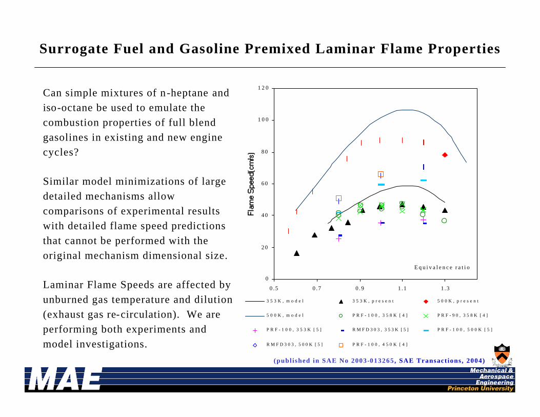
Surrogate Fuel and Gasoline Premixed Laminar Flame Properties
Can simple mixtures of n-heptane and iso-octane be used to emulate the combustion properties of full blend gasolines in existing and new engine cycles?
Similar model minimizations of large detailed mechanisms allow comparisons of experimental results with detailed flame speed predictions that cannot be performed with the original mechanism dimensional size.
Laminar Flame Speeds are affected by unburned gas temperature and dilution (exhaust gas re-circulation). We are performing both experiments and model investigations.
(publ ished in SAE No 2003-013265 , SAE Transact ions , 2004)

R e s i d e n c e T i m e , s e c
0 . 0 0 . 1 0 . 2 0 . 3 0 . 4 0 . 5 0 . 6 0 . 7 0 . 8 0 . 9
Mo
le F
rac
tio
n C
O,
O 2, C
O 2
0.000
0.002
0.004
0.006
0.008
0.010
0.012
0.014
0.016
U T G - 9 6 C OU T G - 9 6 O 2
U T G - 9 6 C O 28 7 O N P R F C O8 7 O N P R F O 2
8 7 O N P R F C O 2
Conventional Fuel Comparisons with Gasoline Surrogates
Comparison of species time
histories for a Reference Gasoline (MON=89) and an ON 87 Primary Reference Fuel
under β-scission dominated conditions. P = 6 atm, T ≈923K, φ=1.0, 1% Carbon.
These type of data and comparisons with results using simple component mixtures can be used to develop
simple mixtures of components that behave as full blend fuels.Ternary blends of components are
presently under investigation
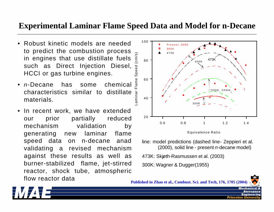
• Robust kinetic models are needed to predict the combustion process in engines that use distillate fuels such as Direct Injection Diesel, HCCI or gas turbine engines.
• n-Decane has some chemical characteristics similar to distillate materials.
• In recent work, we have extended our prior partially reduced mechanism validation by generating new laminar flame speed data on n-decane anadvalidating a revised mechanism against these results as well as burner-stabilized flame, jet-stirred reactor, shock tube, atmospheric flow reactor data
20
40
60
80
100
0.6 0.8 1 1.2 1.4
P r e s e n t , 5 0 0 K
3 0 0 K
4 7 3 K
La
min
ar
Fla
me
Sp
ee
d (
cm
/s)
Equiva lence Rat io
5 0 0 K
3 0 0 K
5 0 0 K , 2 0 % N2
473K
line: model predictions (dashed line- Zeppieri et al. (2000), solid line - present n-decane model)
473K: Skjøth-Rasmussen et al. (2003)
300K: Wagner & Dugger(1955)
Published in Zhao et al., Combust. Sci. and Tech, 176, 1705 (2004)
Experimental Laminar Flame Speed Data and Model for n-Decane
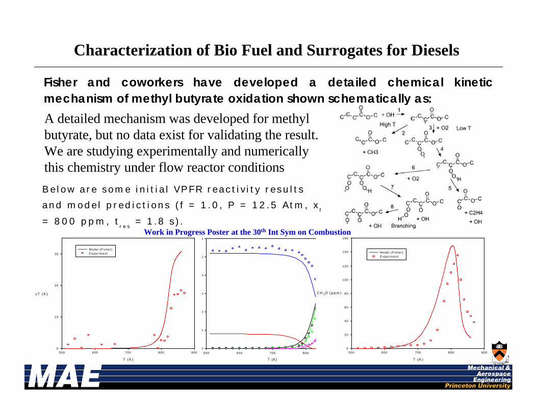
Fisher and coworkers have developed a detailed chemical kinetic mechanism of methyl butyrate oxidation shown schematically as:
A detailed mechanism was developed for methyl butyrate, but no data exist for validating the result. We are studying experimentally and numerically this chemistry under flow reactor conditions
T (K)
500 600 700 800 900
Sp
ec
ies
(m
ole
%)
0.0
0.1
0.2
0.3
0.4
0.5
0.6
T ( K )
500 600 700 800 900
CH 2O ( p p m )
0
20
40
60
80
100
120
140
160
Model (Fisher)Exper iment
T ( K )
500 600 700 800 900
∆ T ( K )
0
10
20
30
Model (Fisher)Exper iment
Below are some in i t ia l VPFR react iv i ty resu l ts
and model pred ict ions ( f = 1 .0 , P = 12.5 Atm, xf
= 800 ppm, tr e s
= 1.8 s) .
Characterization of Bio Fuel and Surrogates for Diesels
Work in Progress Poster at the 30th Int Sym on Combustion
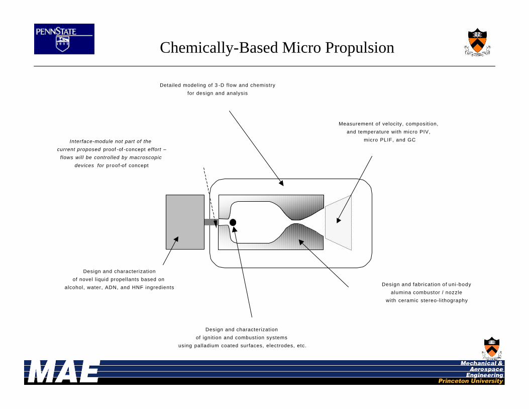
Chemically-Based Micro Propulsion
Design and fabrication of uni-bodyalumina combustor / nozzle
with ceramic stereo-l i thography
Measurement of velocity, composition, and temperature with micro PIV,
micro PLIF, and GC
Design and characterizationof novel l iquid propellants based on
alcohol, water, ADN, and HNF ingredients
Design and characterizationof ignition and combustion systems
using palladium coated surfaces, electrodes, etc.
Detailed modeling of 3 -D f low and chemistryfor design and analysis
Interface-module not part of the current proposed proof -of -concept effort –
flows will be controlled by macroscopic devices for proof-of concept

Fuel
AirP
T igniter
Thruster Prototype Design and Fabrication
Wireframe of thruster body
Fabrication: Ceramic Stereolithography
Materials: Mullite (3Al2O3.2SiO2) and alumina
Unique Features: • 3-dimensional uni-body structures• high temperature capability• materials compatibility
Microscope backlit imageof throat x-section
~ 400 µm
Alumina Thruster Body
3.5 mm
Back-view
Thruster body (Front-view) and Cold Flow Manifold
Hot Flow Manifold Illustrating Combustor VortexFlow with Gaseous Fuel. For Liquid Propellant,Air Port is replaced with Liquid Port
Thruster Design: Gas-phase combustionbased on asymmetric whirl combustion
Features: high flame stability, minimal heat loss, increased particle flow time, film cooling by liquid fuel vaporization and endothermic decomposition along combustor wall
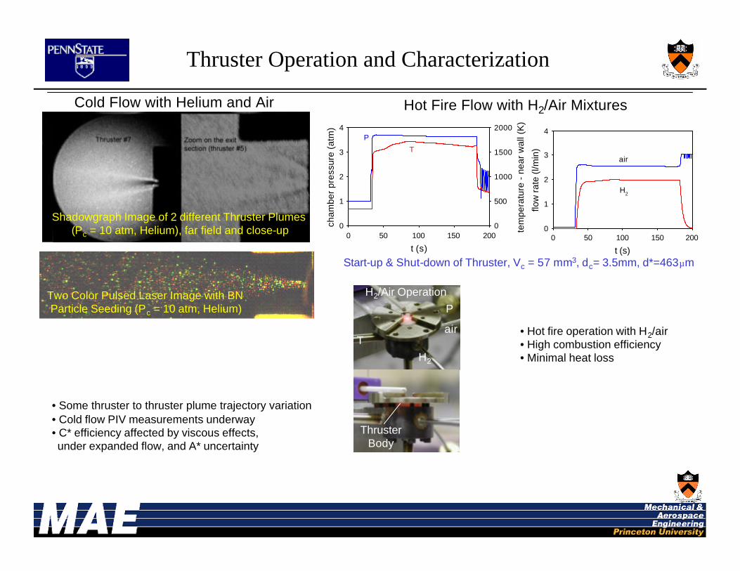
Cold Flow with Helium and Air
Shadowgraph Image of 2 different Thruster Plumes (Pc = 10 atm, Helium), far field and close-up
t (s)
0 50 100 150 200
flow
rat
e (l
/min
)
0
1
2
3
4
air
H2
t (s)
0 50 100 150 200
cha
mb
er
pre
ssu
re (
atm
)
0
1
2
3
4
tem
pera
ture
- n
ear
wal
l (K
)
0
500
1000
1500
2000P
T
Two Color Pulsed Laser Image with BN Particle Seeding (Pc = 10 atm, Helium)
Start-up & Shut-down of Thruster, Vc = 57 mm3, dc= 3.5mm, d*=463µm
Hot Fire Flow with H2/Air Mixtures
ThrusterBody
Thruster Operation and Characterization
• Hot fire operation with H2/air• High combustion efficiency • Minimal heat loss
P
air
H2
T
• Some thruster to thruster plume trajectory variation • Cold flow PIV measurements underway• C* efficiency affected by viscous effects, under expanded flow, and A* uncertainty
H2/Air Operation

Laser Ignition of Ethanol/Oxygen Sprays under Simulated Space Conditions
•Ethanol is a viable alternative to extremely environmentally unfriendly hypergolic fuels, presently used for Orbital Maneuvering Systems (OMS) of NASA spacecraft. A prototype laser ignition system was developed to ignite impinging sprays of ethanol and liquid oxygen (top left). Laser–induced plasma (bottom left) is used as an ignition spark. Conventional electric spark plugs wear extremely fast in such a heavily oxidizing environment. To simulate the space conditions, experiments were conducted in a vacuum chamber, as indicated by the checkered pattern of the pilot flame (below).
Work in Progress Poster at the 30th Int Sym on Combustion
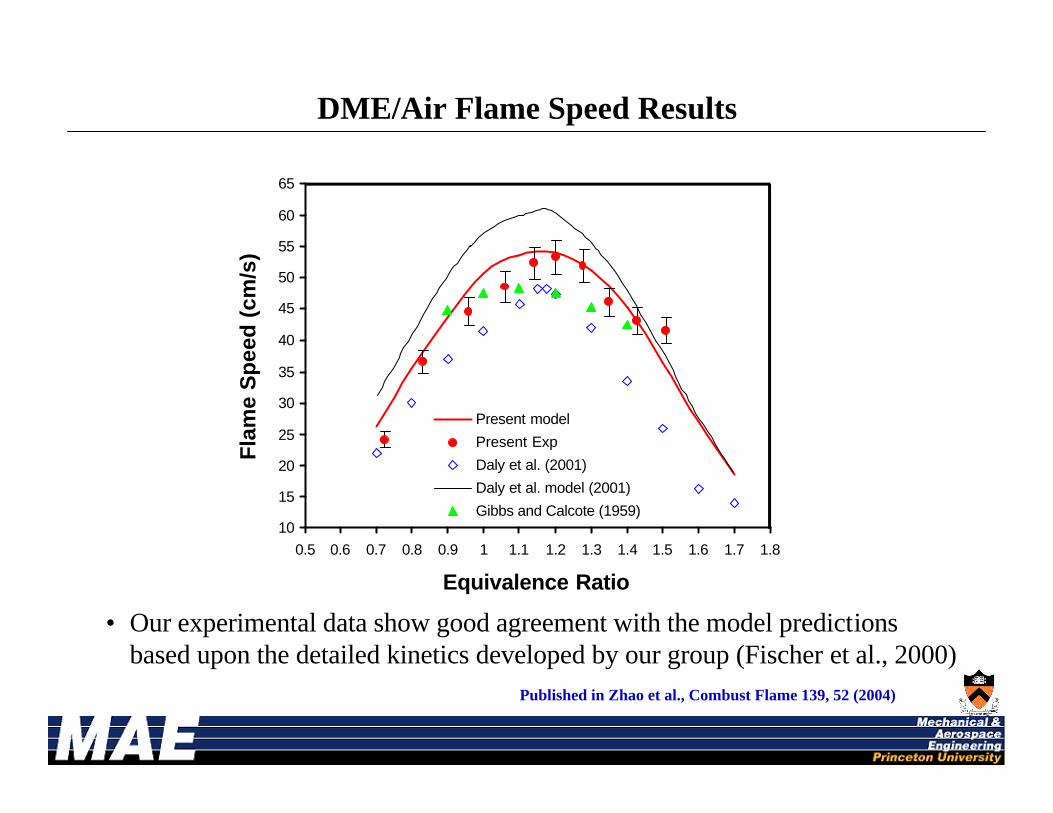
DME/Air Flame Speed Results
• Our experimental data show good agreement with the model predictions based upon the detailed kinetics developed by our group (Fischer et al., 2000)
10
15
20
25
30
35
40
45
50
55
60
65
0.5 0.6 0.7 0.8 0.9 1 1.1 1.2 1.3 1.4 1.5 1.6 1.7 1.8
Equivalence Ratio
Fla
me
Sp
eed
(cm
/s)
Present model
Present Exp
Daly et al. (2001)
Daly et al. model (2001)
Gibbs and Calcote (1959)
Published in Zhao et al., Combust Flame 139, 52 (2004)

•Simulations of 2 mm n-heptane droplets in the listed mole fraction of CO2 mixed with air (21% O2/79% N2).•As CO2 mole fraction is increased, extinction, as characterized by a region of high negative curvature, begins at higher temperatures. This time corresponds exactly with a rapid decrease in burning rate.•The rapid decrease in standoff ratio which occurs near extinction corresponds exactly with 1250 K. It therefore decorrelates from extinction time as the mole fraction of CO2 increases.•As visible in the temperature profiles at differing times within a characteristic burning history, we see the fundamental difference between the temperature profile before the decrease in standoff and thereafter is the loss of a sharp peak. This peak is associated with local heat generation, and thus chemical reaction.•We therefore have a simple technique for differentiating kinetically-limited extinction from extinction resulting from other effects.•The suppressant effect of carbon dioxide is therefore not only because of an increase in local heat capacity, but also due to some more active source of heat loss. These losses could most easily be attributed to an increase in spectral radiative heat transfer from the flame zone.
Physical v Kinetically-Limited Droplet Burning Extinction
Work in Progress Poster at the 30th Int Sym on Combustion