Embed Size (px)
Citation preview

Combusting and Gasification Using Discrete Phase Method
Combustion Through a Chamber

BACKGROUND: Gasification and Coal Combustion
Ash Deposition
Slagging and Slag Disposal
Fouling Downstream
[McDaniel, 2002]

GOVERNING EQUATIONS
Gas Phase Equations
mSVt
xFgPVVt
ik
t
ii
j
j
i
i
jt
ii x
k
xx
u
x
u
x
u
x
ku
kC
xxx
u
x
u
x
u
kC
xu
ji
t
ii
j
j
i
i
jt
ii
2
21
Generation DestructionDiffusionConvection
Turbulent Kinetic Energy
Dissipation

GOVERNING EQUATIONS (Continue)
S
x
Tk
x
hu
t
H
t
h
ii
i
ii
i
ii
i
iii SRx
J
x
mu
t
m
,
i
i
t
tmiii x
m
ScDJ
,,
RN
kkiii RMR
1,
N
j
N
j
njkb
njkfkikiki
kjkj CkCkR1 1
,,,,,,,
Conservation of Energy
Conservation of Species
Mass Diffusion Tensor
Mass Rate
Molecular Rate of Destruction and Creation of Species

Constitutive Equations
x
p
pxpD
p FguuFt
u
44PRPP
PP TATThA
dt
dTmc
Force Momentum Balance
Heat Balance
Tp
T∞
Cd,b
Cd,s
Ck
Tem
perature
Con
cent
ratio
n
Distance
Tp
T∞
Cd,b
Cd,s
Ck
Tp
T∞
Cd,b
Cd,s
Ck
Tem
perature
Con
cent
ratio
n
Distance
productsgspeciesgassspeciessolid )(_)(_
Surface Reactions

FORMULATION OF PROBLEM USING FLUENT
Tw 0.5m
1 m
10 m
.125 m.250 m
Coal Injection: 0.1 kg/s
Air: 15 m/s 1500K
Air: 50 m/s
Symmetry Plane
Tw 0.5m
1 m
10 m
.125 m.250 m
Coal Injection: 0.1 kg/s
Air: 15 m/s 1500K
Air: 50 m/s
Symmetry Plane
Boundary Condition Secondary Air Primary Air Pressure Outlet
Velocity 15 m/s 50m/s ------------------------
Temperature 1500K 1500K 2000K
Turbulence Intensity 10% 5% 5%
Hydraulic Diameter .75 .25 1 m
Oxygen Mass Fraction .23 .23 .23
Schematic of Domain
Boundary Conditions

SOLUTION
Temperature ProfileMass Fraction of H2OMass Fraction of CO2Mass Fraction of CO

SOLUTION (CONTINUED)
Particle Residence Time

PARAMETRIC ANALYSISMole Fraction of Medium Volatile Coal at Selected Operating
Temperatures as a Function of the Duct Length
1500 K Case

PARAMETRIC ANALYSISMole Fraction of Medium Volatile Coal at Selected Operating
Temperatures as a Function of the Duct Length
1000 K Case

PARAMETRIC ANALYSISMole Fraction of Medium Volatile Coal at Selected Operating
Temperatures as a Function of the Duct Length
2000 K Case
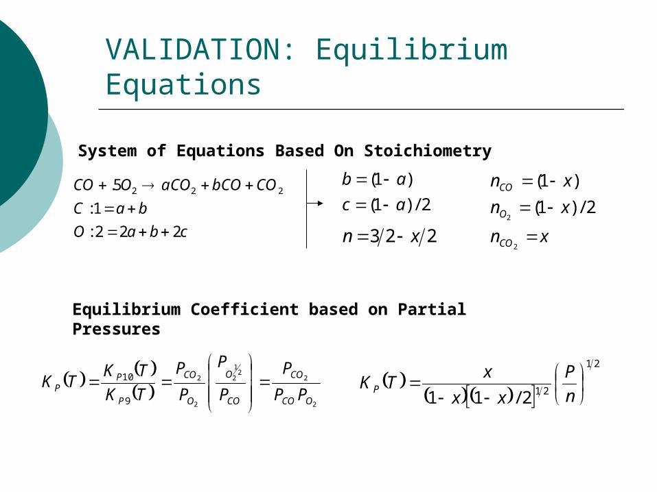
VALIDATION: Equilibrium Equations
cbaO
baC
CObCOaCOOCO
222:
1:
5. 222
2/)1(
)1(
ac
ab
xn
xn
xn
CO
O
CO
2
22/)1(
)1(
223 xn
2
22
1
2
2
2
9
10
OCO
CO
CO
O
O
CO
P
PP PP
P
P
P
P
P
TK
TKTK
21
212/11
n
P
xx
xTK P
System of Equations Based On Stoichiometry
Equilibrium Coefficient based on Partial Pressures

VALIDATION CONTINUE
215902.82247.
177573.
82247.
0887865.2/)1(
177573.)822427.1()1(
2
2
2
CO
CO
CO
O
CO
n
n
xn
xn
xn
Values for Fractions
The ratio of CO to CO2 in Fluent was .247Difference between Calculated and Fluent is 14%

Reference
1. McDaniel, J., Tampa Electric Polk Power Station Integrated Combined Cycle Project Final Report. 2002, Tampa Electric Company: Tampa. p. 1-15-1-71.


![An Integrated Process for Hydrogen Production from Solid ... · from Solid Fuel Gasification. ... Combustion Gasification [Lv, Renewable Energy 2007] ... by CPR-EA * extension to](https://img.pdfslide.us/doc/110x75/5abfc06f7f8b9add5f8e1de9/an-integrated-process-for-hydrogen-production-from-solid-solid-fuel-gasification.jpg)