Embed Size (px)
Citation preview
COMBI VERT
GB INSTRUCTION MANUALPower Supply
and Regenerative UnitType R6-S Size 29
Mat.No. Rev.00R6SEB-KP00 1H

GB This instruction manual describes the power supply and regenerative unit KEB COMBIVERT R6-S. Before working with the unit the user must become familiar with it. This especially applies to the knowledge and observance of the following safety and warning indications. The pictographs used in this instruction manual have following meaning:
Danger Attention InformationWarning Essential Mea-
sureHelp
Caution Tip
GB - 3
1. Introduction .................................................41.1 Preface ............................................................ 41.2 Product description ....................................... 41.3 Validity and liability ........................................ 51.4 Copyright ........................................................ 51.5 Specifiedapplication ..................................... 51.5.1 Standard operation ........................................... 51.5.2 Abnormal operation .......................................... 51.6 Unitidentification ........................................... 6
2. Safety Instructions .....................................72.1 General instructions ...................................... 72.2 Transport, storage and installation .............. 72.3 Electrical connection ..................................... 82.4 EMC Instructions ...........................................112.5 EMC conform installation .............................11
3. Technical Data ..........................................123.1 Overload (OL) function ................................ 133.2 Operating conditions ................................... 133.3 Accessories .................................................. 143.4 Options .......................................................... 143.4.1 Ferrite rings .................................................... 153.5 Dimensions and weights ............................. 163.5.1 Dimensions air-cooled inverter mounting
version ............................................................ 163.5.2 Commutation reactor ...................................... 173.5.3 Side-mountedEMIfilter .................................. 183.5.4 Synchronization unit ....................................... 18
4. Installation .................................................194.1 EMC-compatible control cabinet
installation .................................................... 194.2 Installation instructions ............................... 194.3 Connection of the COMBIVERT R6 ............ 204.3.1 General description of inverter input
terminals ......................................................... 204.3.2 Connection terminals of the power circuit ...... 214.3.3 External fan power supply .............................. 224.3.4 Connections of the control board ................... 224.3.5 Connection of the synchronization unit .......... 234.4 Connection Power Unit R6 .......................... 244.4.1 Supply and regenrative operation at inverter
current≤currentofoneCOMBIVERTR6-S .. 244.4.2 Supply and regenrative operation at inverter
currents≤currentofoneCOMBIVERTR6-S . 254.4.3 Power supply and regenerative operation at
parallel operation of up to three R6-S ............ 264.4.4 Regenerative operation at parallel operation of
up to three R6-S with decoupling diodes ....... 294.5 Connection of the control board version S 314.5.1 Assignment of the control terminal strip X2A . 314.5.2 Assignment of socket X2B ............................. 314.5.3 Wiring example .............................................. 32
Table of Contents
4.6 Operator ........................................................ 33
5. Operation of the Unit ................................345.1 Keyboard ....................................................... 345.2 Operation with PC und system software
COMBIVIS ..................................................... 345.3 Switch-on procedure ................................... 345.4 Parameter summary ..................................... 365.5 Password input ............................................ 375.6 Monitoring and analysis parameters .......... 375.7 Special adjustments .................................... 41
Appendix A ......................................................44A.1 Dimensioning power supply and
regenerative units ........................................ 44A.2 DC link capacitors of KEB frequency
inverters ........................................................ 45A.3 Decoupling diodes ....................................... 45A.3.1 Assignment .................................................... 45A.3.2 Dimensions .................................................... 46
Appendix B ......................................................47B.1 Certification .................................................. 47B.1.1 CE Marking .................................................... 47
GB - 4
Preface
1. Introduction1.1 Preface
First we would like to welcome you as a customer of the company Karl E. Brinkmann GmbH and congratulation to the purchase of this product. You have decided for a product on highest technical niveau. Theencloseddocumentsaswellasthespecifiedhard-andsoftwarearedevelopmentsoftheKarl E. Brinkmann GmbH. Errors excepted. The Karl E. Brinkmann GmbH has created these documents, this hard- and software with best the knowledge. We doesn´t accept the guarantee thattheusergetstheprofitwiththisspecifications.TheKarlE.BrinkmannGmbHreservestherighttochangespecificationswithoutpriornoticeorto instructthirdpersons.This list isnotexhaustive.
Theusedpictogramshavefollowingsignificance:DangerWarningCaution
AttentionEssentialDischarge Time
InformationHelpTip
1.2 Product descriptionThis instruction manual describes the power supply and regenerative unit KEB COMBIVERT R6-S. The COMBIVERT R6-S has the following features.The supply unit
converts a three-phase input voltage into DC voltage. •supplies KEB frequency inverter individually or via DC interconnection.•can be switched parallel, if higher power supply is required.•increases the stability of the DC link voltage in the DC interconnection.•
The regenerative unitfeeds back the excess energy from generatoric operation into the supply system.•reduces the energy demand.•reduces the heat emission.•is environmentally friendly and space-saving.•replaces braking resistor and braking transistor.•is cost-saving.•
The COMBIVERT R6-S is generally protected against overcurrent, ground fault and tempera-ture. Appropriate dimensioned DC fuses protects the DC link circuit against short-circuit. The following accessories are necessary for operation with the COMBIVERT R6-S:
Power choke•EMIfilter(forobservanceofEMCstandard)•
GB - 5
Preface
1.3 Validity and liabilityApplication and use of our units in the target products is outside of our control and the-refore exclusively in the area of responsibility of the machine manufacturer.The information contained in the technical documentation, as well as any user-specific advice in spoken and written and through tests, are made to best of our knowledge and information about the application. However, they are considered for information only without responsibility. This also applies to any violation of industrial property rights of a third-party.Selection of our units in view of their suitability for the intended use must be done generally by the user. Inspections and tests can only be done by the machine manufacturer within the framework of the application. Inspections and tests must be repeated, even if only parts of hardware, soft-ware or the unit adjustment are modified. Unauthorized opening and improper tampering can lead to bodily injuries or liability insurances and this cause loss of the warranty. Original spare parts and authorized accessories by the manufacturer serve as security. The use of other parts excludes liability for the consequences arising out of.The suspension of liability is especially valid also for shutdown damages, lost profit, data loss or other consequential damages. This is also valid, if we have been referred to the possibility of such damages.Should any part of this agreement be invalid for any reason, it is to be replaced with a corre-sponding text, which is valid and equivalent to the intended meaning. The rest of the agree-ment shall remain unaffected and valid.
1.4 CopyrightThe customer may be use the instruction manual as well as further enclosed documents or parts from it for internal purposes. KEB has the copyrights and they remain effective also to the full extent.
1.5 SpecifiedapplicationThe COMBIVERT R6-S serves exclusively for the supply of frequency inverters with DC input and/or regeneration of excess energy into the supply system. The operation of other electrical consumers is prohibited and can lead to malfunctions or to the destruction of the units.
1.5.1 Standard operationIftheDClinkvoltageincreasestoavalueabovethepeakvalueofthemainsvoltage(negativepower),feedbackofthecurrentintothemainsoccursautomatically.Themainsvoltageisana-logmeasured.Thefeedbackoccursinasquare-waveformat,wherebythecurrentflowperiodcorrespondstothetimesofaB6bridgecircuit.RegenerationisfinishediftheDClinkvoltagedecreasesthesupplypeakvoltage(positivepower).
1.5.2 Abnormal operationWhen exceeding the permissible limit values for voltage, current or temperature the current flowbetweenDClinkandmainsisblockedduringregeneration.Anappropriateerrormessageis also displayed during supply. The unit must be disconnected from the supply system or the load must be switched off in case of overcurrent. This can be done by opening the control re-lease of the frequency inverter.At factory setting the modulation is switched off in case of a net phase and/or a synchronisation line failure and the error message E.nEt is displayed.Special adjustments from KEB are necessary if the modulation and/or the standard operation shouldstartagainwithinadefinedtimeincaseofreturnofpowersupply.
GB - 6
Preface
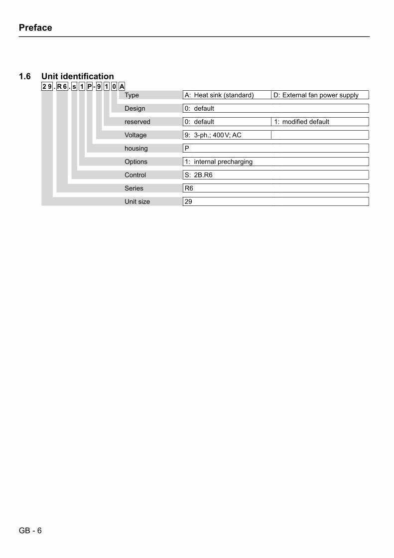
1.6 Unitidentification2 9 . R 6 . s 1 P - 9 1 0 A
Type A: Heatsink(standard) D: External fan power supply
Design 0: default
reserved 0: default 1: modifieddefault
Voltage 9: 3-ph.; 400 V; AC
housing P
Options 1: internal precharging
Control S: 2B.R6
Series R6
Unit size 29
GB - 7
Safety Instructions
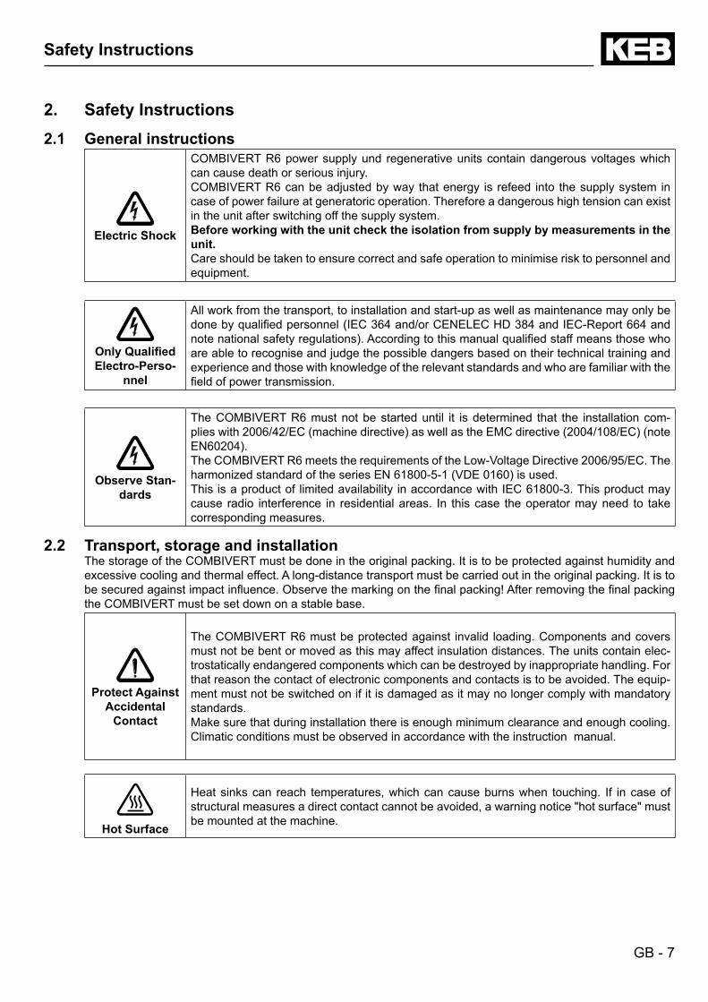
2. Safety Instructions2.1 General instructions
Electric Shock
COMBIVERT R6 power supply und regenerative units contain dangerous voltages which can cause death or serious injury. COMBIVERT R6 can be adjusted by way that energy is refeed into the supply system in case of power failure at generatoric operation. Therefore a dangerous high tension can exist in the unit after switching off the supply system.Before working with the unit check the isolation from supply by measurements in the unit.Care should be taken to ensure correct and safe operation to minimise risk to personnel and equipment.
OnlyQualifiedElectro-Perso-
nnel
All work from the transport, to installation and start-up as well as maintenance may only be donebyqualifiedpersonnel(IEC364and/orCENELECHD384andIEC-Report664andnotenationalsafetyregulations).Accordingtothismanualqualifiedstaffmeansthosewhoare able to recognise and judge the possible dangers based on their technical training and experience and those with knowledge of the relevant standards and who are familiar with the fieldofpowertransmission.
Observe Stan-dards
The COMBIVERT R6 must not be started until it is determined that the installation com-plieswith2006/42/EC(machinedirective)aswellastheEMCdirective(2004/108/EC)(noteEN60204).TheCOMBIVERTR6meetstherequirementsoftheLow-VoltageDirective2006/95/EC.TheharmonizedstandardoftheseriesEN61800-5-1(VDE0160)isused.This is a product of limited availability in accordance with IEC 61800-3. This product may cause radio interference in residential areas. In this case the operator may need to take corresponding measures.
2.2 Transport, storage and installationThe storage of the COMBIVERT must be done in the original packing. It is to be protected against humidity and excessive cooling and thermal effect. A long-distance transport must be carried out in the original packing. It is to besecuredagainstimpactinfluence.Observethemarkingonthefinalpacking!Afterremovingthefinalpackingthe COMBIVERT must be set down on a stable base.
Protect Against Accidental
Contact
The COMBIVERT R6 must be protected against invalid loading. Components and covers must not be bent or moved as this may affect insulation distances. The units contain elec-trostatically endangered components which can be destroyed by inappropriate handling. For that reason the contact of electronic components and contacts is to be avoided. The equip-ment must not be switched on if it is damaged as it may no longer comply with mandatory standards.Make sure that during installation there is enough minimum clearance and enough cooling. Climatic conditions must be observed in accordance with the instruction manual.
Hot Surface
Heat sinks can reach temperatures, which can cause burns when touching. If in case of structural measures a direct contact cannot be avoided, a warning notice "hot surface" must be mounted at the machine.
GB - 8
Safety Instructions
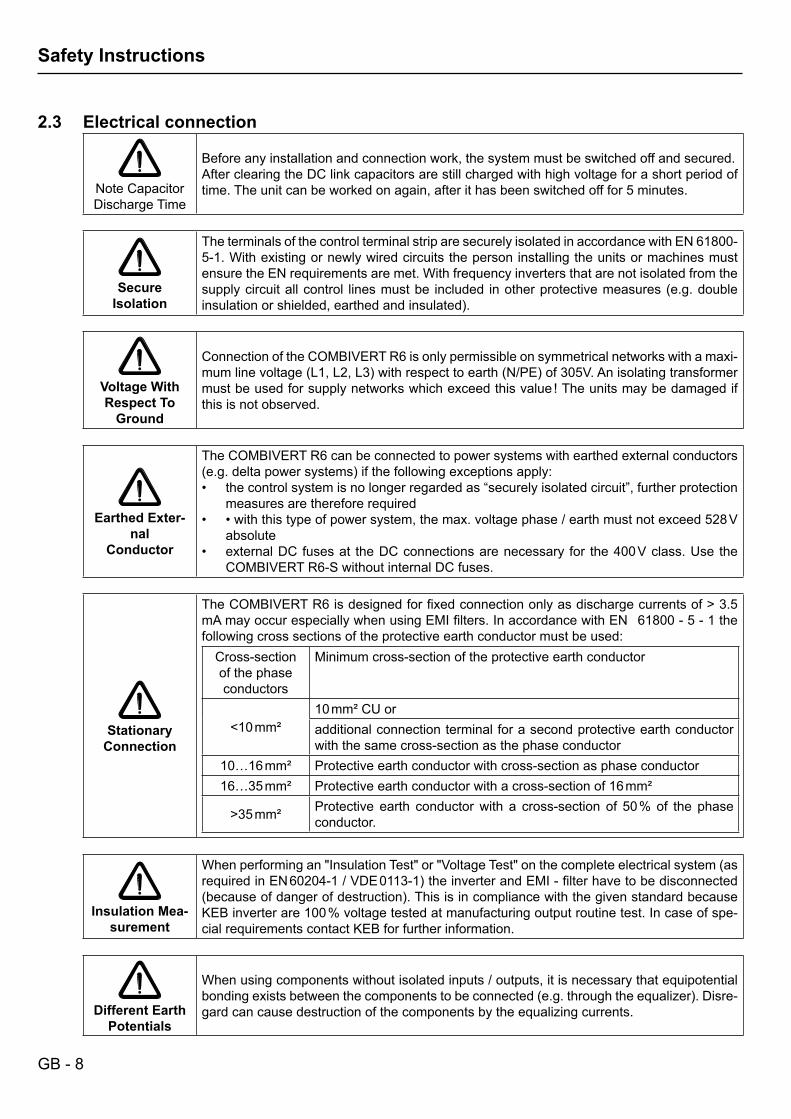
2.3 Electrical connection
Note Capacitor Discharge Time
Before any installation and connection work, the system must be switched off and secured.After clearing the DC link capacitors are still charged with high voltage for a short period of time. The unit can be worked on again, after it has been switched off for 5 minutes.
Secure Isolation
The terminals of the control terminal strip are securely isolated in accordance with EN 61800-5-1. With existing or newly wired circuits the person installing the units or machines must ensure the EN requirements are met. With frequency inverters that are not isolated from the supplycircuitallcontrol linesmustbe included inotherprotectivemeasures(e.g.doubleinsulationorshielded,earthedandinsulated).
Voltage With Respect To
Ground
Connection of the COMBIVERT R6 is only permissible on symmetrical networks with a maxi-mumlinevoltage(L1,L2,L3)withrespecttoearth(N/PE)of305V.Anisolatingtransformermustbeusedforsupplynetworkswhichexceedthisvalue!Theunitsmaybedamagedifthis is not observed.
Earthed Exter-nal
Conductor
The COMBIVERT R6 can be connected to power systems with earthed external conductors (e.g.deltapowersystems)ifthefollowingexceptionsapply:
the control system is no longer regarded as “securely isolated circuit”, further protection •measures are therefore required•withthistypeofpowersystem,themax.voltagephase/earthmustnotexceed528V•absoluteexternal DC fuses at the DC connections are necessary for the 400 V class. Use the •COMBIVERT R6-S without internal DC fuses.
Stationary Connection
TheCOMBIVERTR6isdesignedforfixedconnectiononlyasdischargecurrentsof>3.5mAmayoccurespeciallywhenusingEMIfilters.InaccordancewithEN61800-5-1thefollowing cross sections of the protective earth conductor must be used:
Cross-section of the phase conductors
Minimum cross-section of the protective earth conductor
<10 mm²10 mm² CU oradditional connection terminal for a second protective earth conductor with the same cross-section as the phase conductor
10…16 mm² Protective earth conductor with cross-section as phase conductor16…35 mm² Protective earth conductor with a cross-section of 16 mm²
>35mm² Protective earth conductor with a cross-section of 50 % of the phase conductor.
Insulation Mea-surement
Whenperformingan"InsulationTest"or"VoltageTest"onthecompleteelectricalsystem(asrequiredinEN60204-1/VDE0113-1)theinverterandEMI-filterhavetobedisconnected(becauseofdangerofdestruction).ThisisincompliancewiththegivenstandardbecauseKEB inverter are 100 % voltage tested at manufacturing output routine test. In case of spe-cial requirements contact KEB for further information.
Different Earth Potentials
When using components without isolated inputs / outputs, it is necessary that equipotential bondingexistsbetweenthecomponentstobeconnected(e.g.throughtheequalizer).Disre-gard can cause destruction of the components by the equalizing currents.
GB - 9
Safety Instructions
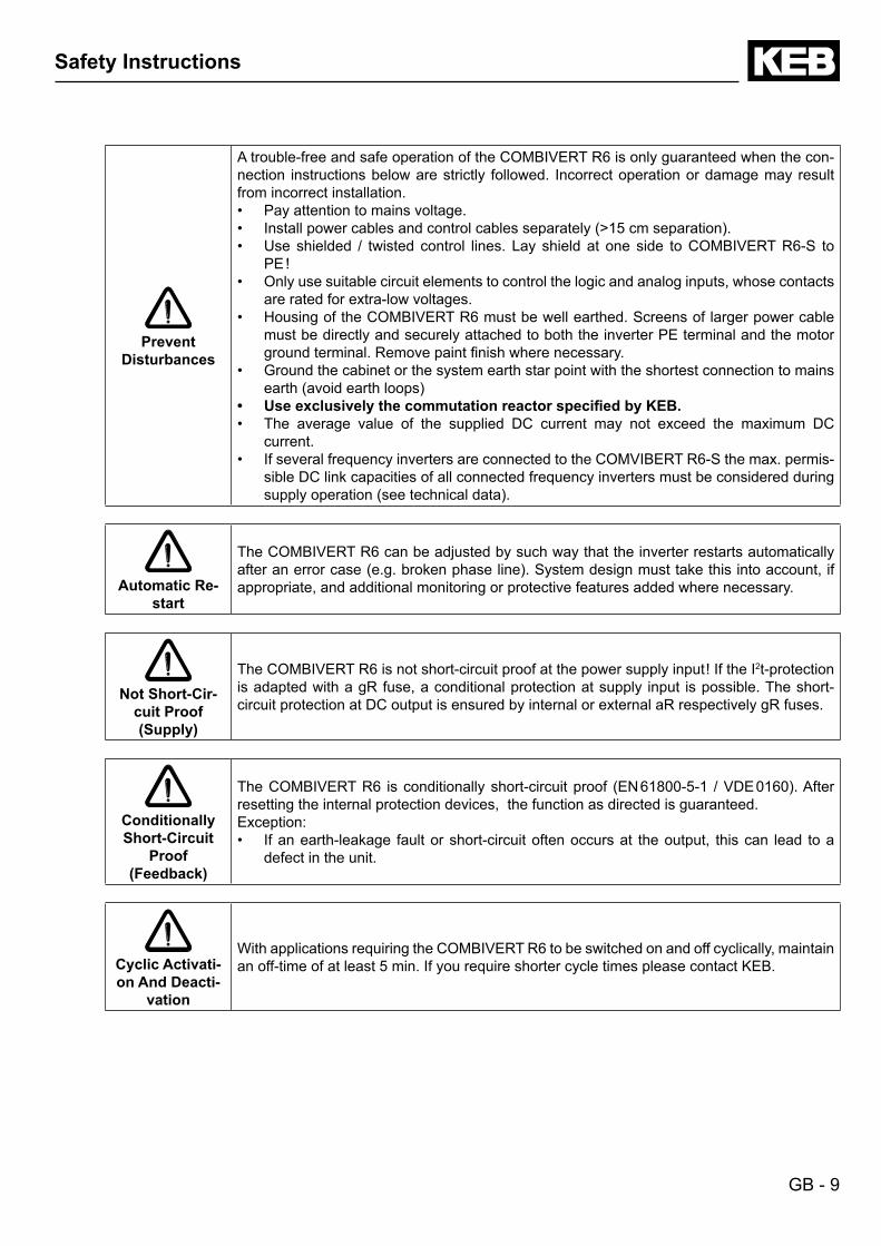
Prevent Disturbances
A trouble-free and safe operation of the COMBIVERT R6 is only guaranteed when the con-nection instructions below are strictly followed. Incorrect operation or damage may result from incorrect installation.
Pay attention to mains voltage.•Installpowercablesandcontrolcablesseparately(>15cmseparation).•Use shielded / twisted control lines. Lay shield at one side toCOMBIVERTR6-S to•PE!Only use suitable circuit elements to control the logic and analog inputs, whose contacts •are rated for extra-low voltages.Housing of the COMBIVERT R6 must be well earthed. Screens of larger power cable •must be directly and securely attached to both the inverter PE terminal and the motor groundterminal.Removepaintfinishwherenecessary.Ground the cabinet or the system earth star point with the shortest connection to mains •earth(avoidearthloops)UseexclusivelythecommutationreactorspecifiedbyKEB.•The average value of the supplied DC current may not exceed the maximum DC •current.If several frequency inverters are connected to the COMVIBERT R6-S the max. permis-•sible DC link capacities of all connected frequency inverters must be considered during supplyoperation(seetechnicaldata).
Automatic Re-start
The COMBIVERT R6 can be adjusted by such way that the inverter restarts automatically afteranerrorcase(e.g.brokenphaseline).Systemdesignmusttakethisintoaccount,ifappropriate, and additional monitoring or protective features added where necessary.
Not Short-Cir-cuit Proof(Supply)
The COMBIVERT R6 is not short-circuit proof at the power supply input !IftheI2t-protection is adapted with a gR fuse, a conditional protection at supply input is possible. The short-circuit protection at DC output is ensured by internal or external aR respectively gR fuses.
Conditionally Short-Circuit
Proof(Feedback)
TheCOMBIVERTR6 isconditionallyshort-circuitproof (EN61800-5-1 /VDE0160).Afterresetting the internal protection devices, the function as directed is guaranteed. Exception:
If an earth-leakage fault or short-circuit often occurs at the output, this can lead to a •defect in the unit.
Cyclic Activati-on And Deacti-
vation
With applications requiring the COMBIVERT R6 to be switched on and off cyclically, maintain an off-time of at least 5 min. If you require shorter cycle times please contact KEB.
GB - 10
Safety Instructions
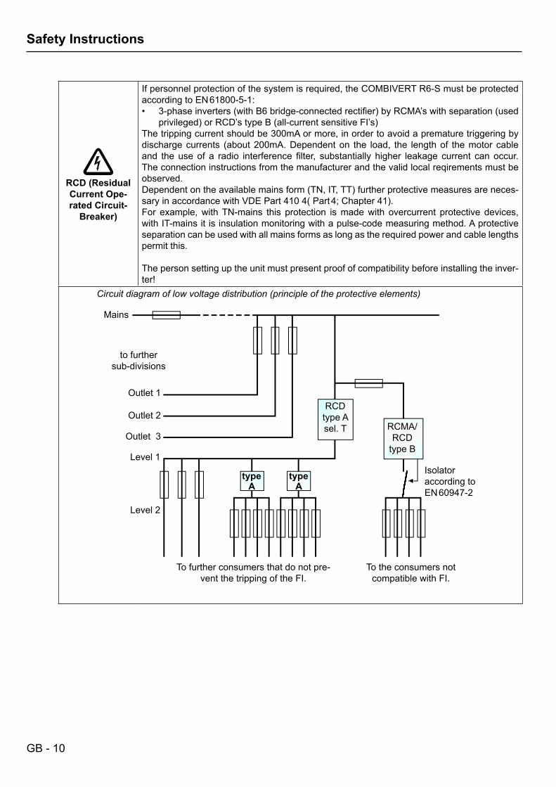
RCD (Residual Current Ope-rated Circuit-
Breaker)
If personnel protection of the system is required, the COMBIVERT R6-S must be protected according to EN 61800-5-1:
3-phaseinverters(withB6bridge-connectedrectifier)byRCMA’swithseparation(used•privileged)orRCD’stypeB(all-currentsensitiveFI’s)
The tripping current should be 300mA or more, in order to avoid a premature triggering by dischargecurrents (about200mA.Dependenton the load, the lengthof themotorcableand theuseof a radio interference filter, substantially higher leakage current canoccur.The connection instructions from the manufacturer and the valid local reqirements must be observed.Dependentontheavailablemainsform(TN,IT,TT)furtherprotectivemeasuresareneces-saryinaccordancewithVDEPart4104(Part4;Chapter41).For example, with TN-mains this protection is made with overcurrent protective devices, with IT-mains it is insulation monitoring with a pulse-code measuring method. A protective separation can be used with all mains forms as long as the required power and cable lengths permit this.
The person setting up the unit must present proof of compatibility before installing the inver-ter!
Circuit diagram of low voltage distribution (principle of the protective elements)
Mains
to furthersub-divisions
Outlet 1
Outlet 2
Outlet 3
Level1
Level2
type A
type A
RCDtype Asel. T RCMA/
RCDtype B
Isolatoraccording to EN 60947-2
To further consumers that do not pre-vent the tripping of the FI.
To the consumers not compatible with FI.
GB - 11
EMC Instructions
2.4 EMC InstructionsCOMBIVERT R6-S represent electrical equipment designed for use in industrial and commercial units. In accor-dance with the EMC directive 2006/108/EC, it is not obligatory to mark these devices as they represent compo-nents to be further processed by the respective machine and unit manufacturer and are not operable indepen-dently according to the EMC directive. The person installing / operating the machine / unit is obliged to proove the protective measures demanded by the EMC directive are complied with. The prescribed ratings can usually be compliedwithwhenusingtheradiointerferencevoltagefiltersspecifiedbyKEB,andwhenobservingthefollowingmeasures and installation guidelines.
2.5 EMC conform installationTheCOMBIVERTR6isdesignedtobeusedinthesecondenvironmentasdefinedinEN61800-3(unitwithitsownsupplytransformer).Takeadditionalmeasureswhenusingitinthefirstenvironment(residentialandcom-mercialareaconnectedtopubliclow-voltagemains)!
Installthecontrolcabinetorsysteminanappropriateandcorrectlyway(seechapter„controlcabinetinstal-•lation“)Toavoidcoupled-innoise,separatesupplylines,motorlines,controlanddatalines(low-voltagelevel<48V)•and leave a space of at least 15 cm between them when installing.In order to maintain low-resistance high frequency connections, earthing and shielding, as well as other metal-•licconnections(e.g.mountingplate,installedunits)mustbeinmetal-to-metalcontactwiththemountingplate,overaslargeanareaaspossible.Makegroundconnectionswithasurfaceaslargeaspossible(earthingstrips).Only use shielded cable with copper or tin-plated braid, since steel braid is not suitable for high frequency •ranges. The screen must always be installed on the compensating rail and fastened with clips or guided throughthewallofthehousing.Donotelongatethescreenend(pigtails)withindividualconductors!Ifexternal interferencesuppressionfiltersareused, then thesemustbe installedascloseaspossible to•(<30cmfrom)theinterferencesourceandinmetal-to-metalcontactwiththemoutingplate,overaslargeanarea as possible.Alwaysequip inductivecontrolelements (contactors, relaysetc.)withsuppressorssuchasvaristors,RC-•elements or damping diodes.Allconnectionsmustbekeptasshortaspossibleandascloseaspossibletotheearth,asfreefloatinglines•work as active and passive aerials.Keepconnectioncablesstraight(donotbundle).Installanon-assignedwireatonesidestotheprotective•earth conductor.Theflowandreturncircuitmustbetwistedwhenthelinesarenotshielded,inordertodampencommon-mode•noise.The cable for phase synchronisation between mains choke and COMBIVERT R6-S may not exceed a line •length of 1 m.Furtherinformationsarefoundintheinternet,see„www.keb.de“.•
GB - 12
Technical Data
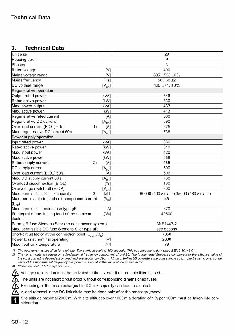
3. Technical DataUnit size 29Housing size PPhases 3Rated voltage [V] 400Mains voltage range [V] 305…528 ±0 %Mains frequency [Hz] 50 / 60 ±2DC voltage range [VDC] 420…747 ±0 %Regenerative operationOutput rated power [kVA] 346Rated active power [kW] 330Max. power output [kVA] 433Max. active power [kW] 413Regenerative rated current [A] 500Regenerative DC current [ADC] 590Overloadcurrent(E.OL)60s 1) [A] 625Max. regenerative DC current 60 s [ADC] 738Power supply operationInput rated power [kVA] 336Rated active power [kW] 310Max. input power [kVA] 420Max. active power [kW] 388Rated supply current 2) [A] 485DC supply current [ADC] 590Overloadcurrent(E.OL)60s [A] 606Max. DC supply current 60 s [ADC] 738Overloaddisconnection(E.OL) [%] 160Overvoltageswitch-off(E.OP) [VDC] 800Max. permissible DC link capacity 3) [µF] 60000(400Vclass)35000(480Vclass)Max. permissible total circuit component current (InOP)
[AAC] ≤6
Max. permissible mains fuse type gR [A] 670I2t Integral of the limiting load of the semicon-ductor
[A2s] 40500
Perm.gRfuseSiemensSitor(nodeltapowersystem) 3NE1447-2Max. permissible DC fuse Siemens Sitor type aR see optionsShort-circuitfactorattheconnectionpoint(Smains/SN) <350Power loss at nominal operating [W] 2800Max. heat sink temperature [°C] 791) The overcurrent is specified for 1 minute. The overload cycle is 300 seconds. This corresponds to duty class 2 EN 2‑60146‑01.2) The current data are based on a fundamental frequency component of g=0,95. The fundamental frequency component or the effective value of
the input current is dependent on load and line supply conditions. At uncontrolled B6 converters the phase angle cosφ1 can be set to one, so the value of the fundamental frequency components is equal to the value of the power factor.
3) Please contact KEB for higher values.
Voltagestabilizationmustbeactivatedattheinverterifaharmonicfilterisused.The units are not short circuit proof without corresponding dimensioned fusesExceeding of the max. rechargeable DC link capacity can lead to a defect.AloadremovalintheDClinkcirclemaybedoneonlyafterthemessage„ready“.Site altitude maximal 2000 m. With site altitudes over 1000 m a derating of 1 % per 100 m must be taken into con-sideration.
GB - 13
Technical Data
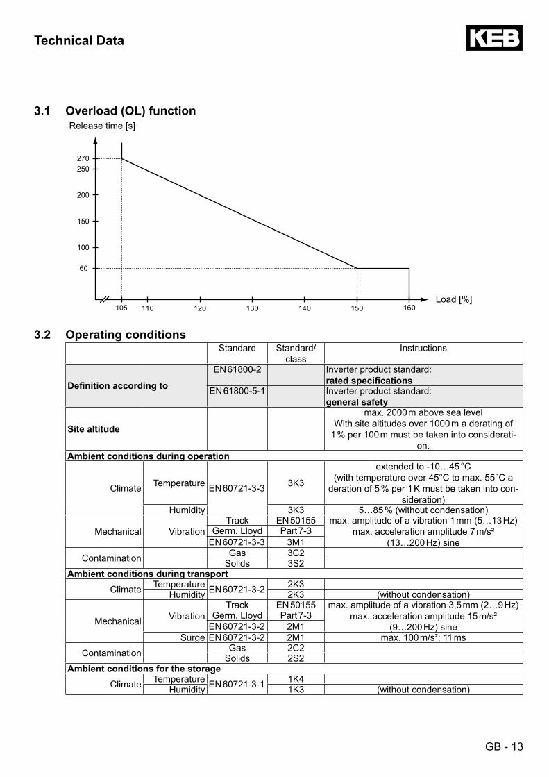
3.1 Overload (OL) functionRelease time [s]
105 110 120 130 140 150 160
100
150
200
250270
60
Load [%]
3.2 Operating conditionsStandard Standard/
classInstructions
Definitionaccordingto
EN 61800-2 Inverter product standard: ratedspecifications
EN 61800-5-1 Inverter product standard: general safety
Site altitude
max. 2000 m above sea levelWith site altitudes over 1000 m a derating of
1 % per 100 m must be taken into considerati-on.
Ambient conditions during operation
Climate Temperature EN 60721-3-3 3K3
extended to -10…45 °C(withtemperatureover45°Ctomax.55°Ca
deration of 5 % per 1 K must be taken into con-sideration)
Humidity 3K3 5…85%(withoutcondensation)
Mechanical VibrationTrack EN 50155 max.amplitudeofavibration1mm(5…13Hz)
max. acceleration amplitude 7 m/s² (13…200Hz)sine
Germ.Lloyd Part 7-3EN 60721-3-3 3M1
Contamination Gas 3C2Solids 3S2
Ambient conditions during transportClimate Temperature EN 60721-3-2 2K3
Humidity 2K3 (withoutcondensation)
Mechanical VibrationTrack EN 50155 max.amplitudeofavibration3,5mm(2…9Hz)
max. acceleration amplitude 15 m/s² (9…200Hz)sine
Germ.Lloyd Part 7-3EN 60721-3-2 2M1
Surge EN 60721-3-2 2M1 max. 100 m/s²; 11 ms
Contamination Gas 2C2Solids 2S2
Ambient conditions for the storageClimate Temperature EN 60721-3-1 1K4
Humidity 1K3 (withoutcondensation)
GB - 14
Technical Data
Mechanical VibrationTrack EN 50155 max.amplitudeofavibration1mm(5…13Hz)
max. acceleration amplitude 7 m/s² (13…200Hz)sine
Germ.Lloyd Part 7-3EN 60721-3-1 1M1
Surge EN 60721-3-1 1M1 max. 100 m/s²; 11 ms
Contamination Gas 1C2Solids 1S2
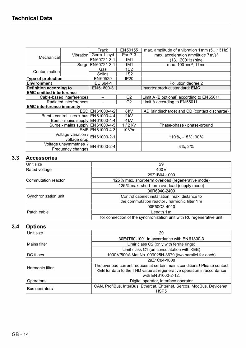
Type of protection EN 60529 IP20Environment IEC 664-1 Pollution degree 2Definitionaccordingto EN 61800-3 Inverter product standard: EMCEMC emitted interference
Cable-based interferences – C2 Limit A (B optional) according to EN 55011Radiated interferences – C2 Limit A according to EN 55011
EMC interference immunityESD EN 61000-4-2 8 kV AD(airdischarge)andCD(contactdischarge)
Burst - control lines + bus EN 61000-4-4 2 kVBurst - mains supply EN 61000-4-4 4 kV
Surge - mains supply EN 61000-4-5 1 / 2 kV Phase-phase / phase-groundEMF EN 61000-4-3 10 V/m
Voltage variation /voltage drop EN 61000-2-1 +10 %, -15 %; 90 %
Voltage unsymmetries / Frequency changes EN 61000-2-4 3 %; 2 %
3.3 AccessoriesUnit size 29Rated voltage 400 V
Commutation reactor29Z1B04-1000
125%max.short-termoverload(regenerativemode)125%max.short-termoverload(supplymode)
Synchronization unit00R6940-2409
Control cabinet installation; max. distance to thecommutationreactor/harmonicfilter1m
Patch cable00F50C3-4010Length1m
for connection of the synchronization unit with R6 regenerative unit
3.4 OptionsUnit size 29
Mainsfilter30E4T60-1001 in accordance with EN 61800-3
LimirclassC2(onlywithferriterings)LimitclassC1(onconsulatationwithKEB)
DC fuses 1000V/500AMat.No.009025H-3679(twoparallelforeach)
Harmonicfilter
29Z1C04-1000The overload current reduces at certain mains conditions ! Please contact KEB for data to the THD value at regenerative operation in accordance
with EN 61000-2-12.Operators Digital operator, Interface operator
Bus operators CAN,ProfiBus,InterBus,Ethercat,Ehternet,Sercos,ModBus,Devicenet,HSP5
GB - 15
Technical Data
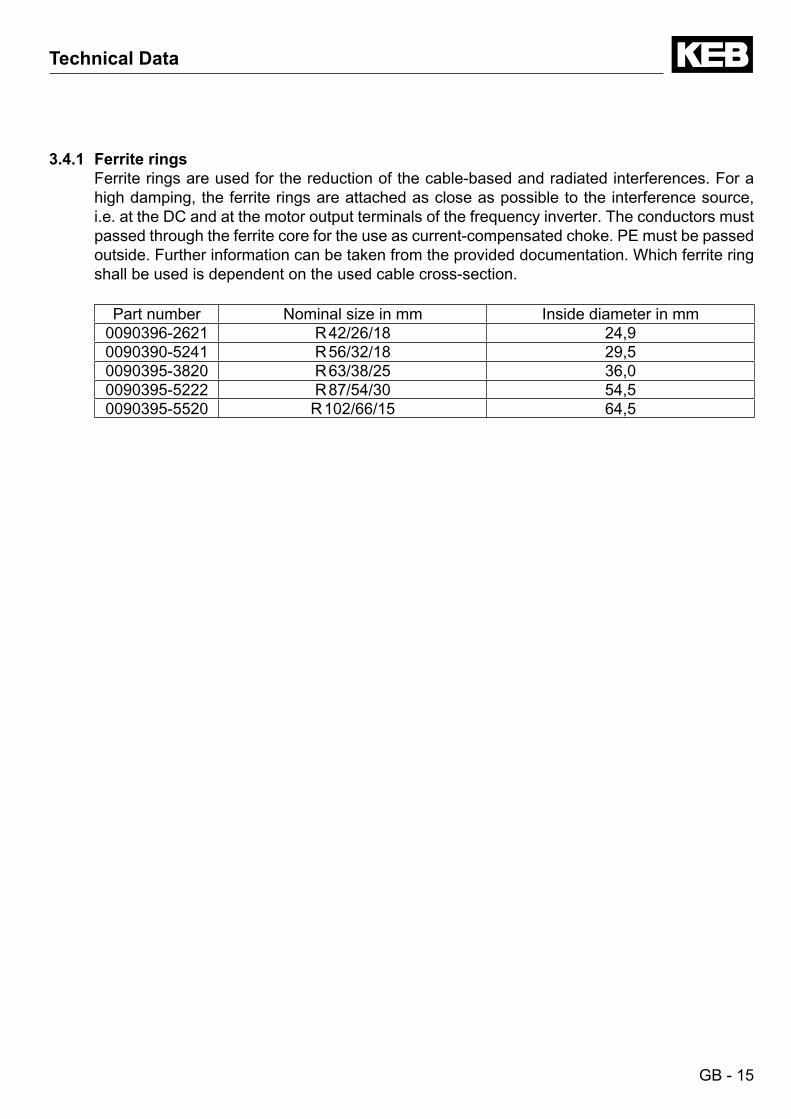
3.4.1 Ferrite ringsFerrite rings are used for the reduction of the cable-based and radiated interferences. For a high damping, the ferrite rings are attached as close as possible to the interference source, i.e. at the DC and at the motor output terminals of the frequency inverter. The conductors must passed through the ferrite core for the use as current-compensated choke. PE must be passed outside. Further information can be taken from the provided documentation. Which ferrite ring shall be used is dependent on the used cable cross-section.
Part number Nominal size in mm Inside diameter in mm0090396-2621 R 42/26/18 24,90090390-5241 R 56/32/18 29,50090395-3820 R 63/38/25 36,00090395-5222 R 87/54/30 54,50090395-5520 R 102/66/15 64,5
GB - 16
Technical Data - Dimensions and Weights
3.5 Dimensions and weights
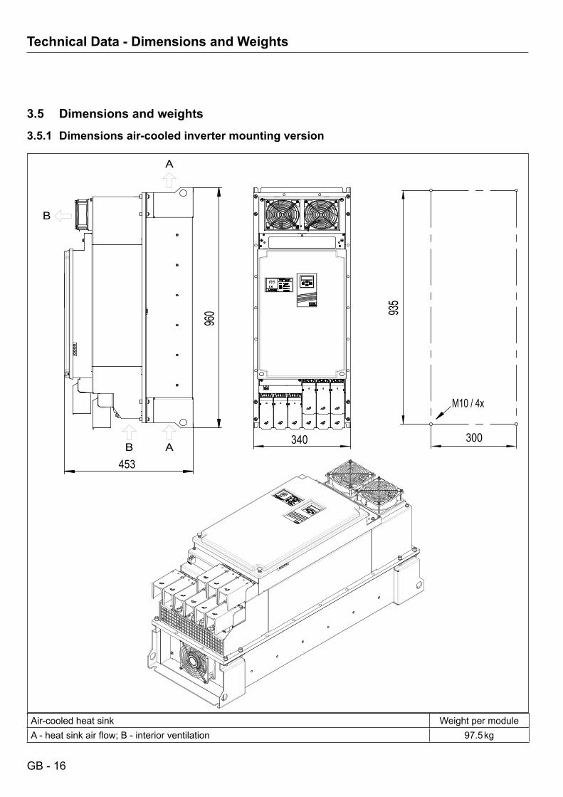
3.5.1 Dimensions air-cooled inverter mounting version
Air-cooled heat sink Weight per moduleA-heatsinkairflow;B-interiorventilation 97.5 kg
453
960 93
5
300340
M10 / 4x
B
B
A
A
R6
GB - 17
Technical Data - Dimensions and Weights
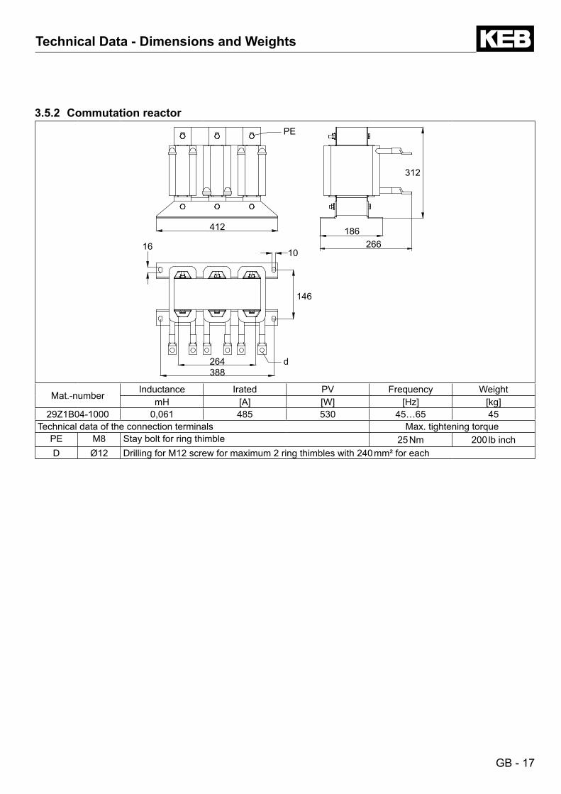
3.5.2 Commutation reactor
412
266186
312
388264
146
1016
d
PE
Mat.-numberInductance Irated PV Frequency Weight
mH [A] [W] [Hz] [kg]29Z1B04-1000 0,061 485 530 45…65 45
Technical data of the connection terminals Max. tightening torquePE M8 Stay bolt for ring thimble 25 Nm 200 lb inchD Ø12 Drilling for M12 screw for maximum 2 ring thimbles with 240 mm² for each
GB - 18
Technical Data - Dimensions and Weights
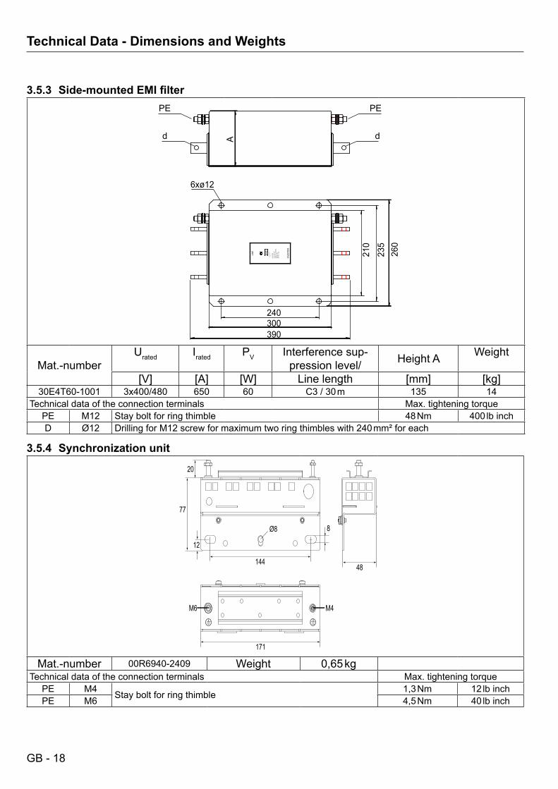
3.5.3 Side-mountedEMIfilter
260
235
210
300 390
240
A
INVE
RTER
3x48
0V +5
% A
C/50
-60H
z
HF-
FILT
ER
30.E
4.T6
0-10
01
Karl
E. B
rinkm
ann
Gm
bH
D-3
2677
Bar
ntru
p
650A
@ T=
45 C
HP
F:-2
5 C -
+85 C
LIN
E
6xø12
PEPE
d d
Mat.-numberUrated Irated PV Interference sup-
pression level/ Height A Weight
[V] [A] [W] Linelength [mm] [kg]30E4T60-1001 3x400/480 650 60 C3 / 30 m 135 14
Technical data of the connection terminals Max. tightening torquePE M12 Stay bolt for ring thimble 48 Nm 400 lb inchD Ø12 Drilling for M12 screw for maximum two ring thimbles with 240 mm² for each
3.5.4 Synchronization unit
171
14448
77
20
M4M6
8
12
Ø8
Mat.-number 00R6940-2409 Weight 0,65 kgTechnical data of the connection terminals Max. tightening torque
PE M4 Stay bolt for ring thimble 1,3 Nm 12 lb inchPE M6 4,5 Nm 40 lb inch
GB - 19
Installation
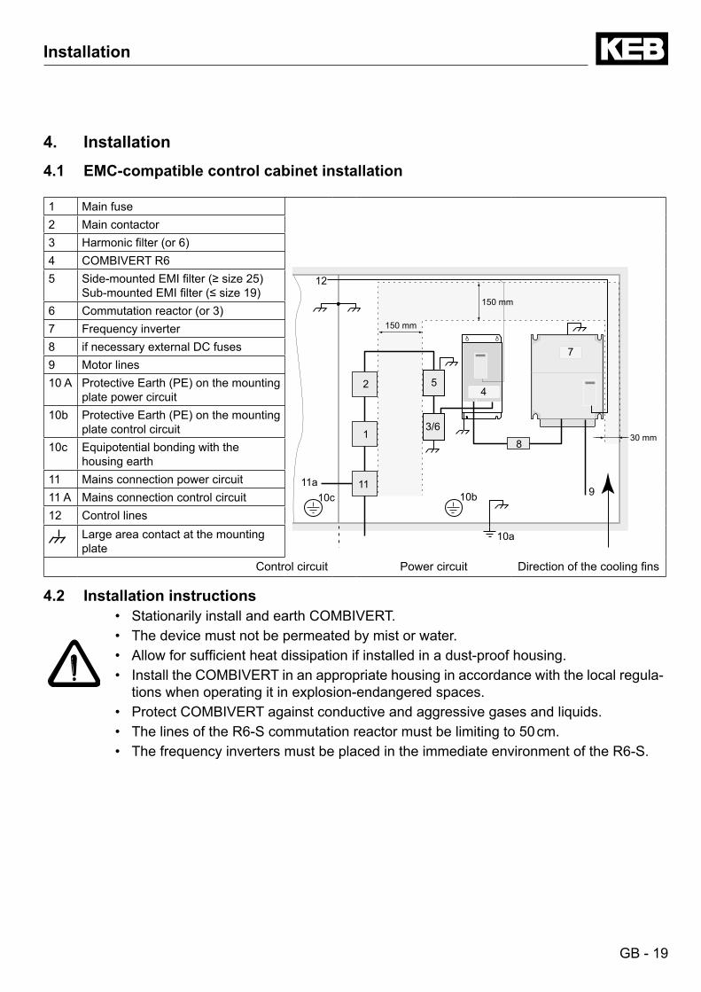
4. Installation4.1 EMC-compatible control cabinet installation
1 Main fuse
150 mm
30 mm
150 mm
1
2
8
7
10b 9 10c
10a
11 11a
12
45
3/6
2 Main contactor3 Harmonicfilter(or6)4 COMBIVERT R65 Side-mountedEMIfilter(≥size25)
Sub-mountedEMIfilter(≤size19)6 Commutationreactor(or3)7 Frequency inverter8 if necessary external DC fuses9 Motor lines10 A ProtectiveEarth(PE)onthemounting
plate power circuit10b ProtectiveEarth(PE)onthemounting
plate control circuit10c Equipotential bonding with the
housing earth11 Mains connection power circuit11 A Mains connection control circuit12 Control lines
Largeareacontactatthemountingplate
Control circuit Power circuit Directionofthecoolingfins
4.2 Installation instructions• Stationarily install and earth COMBIVERT.• The device must not be permeated by mist or water.• Allowforsufficientheatdissipationifinstalledinadust-proofhousing.• Install the COMBIVERT in an appropriate housing in accordance with the local regula-
tions when operating it in explosion-endangered spaces.• Protect COMBIVERT against conductive and aggressive gases and liquids.• The lines of the R6-S commutation reactor must be limiting to 50 cm.• The frequency inverters must be placed in the immediate environment of the R6-S.
GB - 20
Connection Terminals
4.3 Connection of the COMBIVERT R6
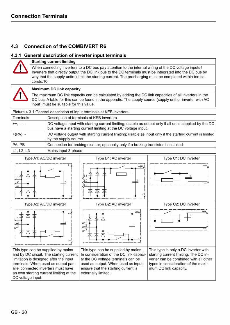
4.3.1 General description of inverter input terminalsStarting current limitingWhenconnectinginverterstoaDCbuspayattentiontotheinternalwiringoftheDCvoltageinputs!Inverters that directly output the DC link bus to the DC terminals must be integrated into the DC bus by waythatthesupplyunit(s)limitthestartingcurrent.Theprechargingmustbecompletedwithintense-conds.10
Maximum DC link capacityThe maximum DC link capacity can be calculated by adding the DC link capacities of all inverters in the DCbus.Atableforthiscanbefoundintheappendix.Thesupplysource(supplyunitorinverterwithACinput)mustbesuitableforthisvalue.
Picture 4.3.1 General description of input terminals at KEB invertersTerminals Description of terminals at KEB inverters++, – – DC voltage input with starting current limiting; usable as output only if all units supplied by the DC
bus have a starting current limiting at the DC voltage input.+(PA),- DC voltage output with starting current limiting; usable as input only if the starting current is limited
by the supply source.PA, PB Connection for braking resistor; optionally only if a braking transistor is installedL1,L2,L3 Mains input 3-phase
Type A1: AC/DC inverter Type B1: AC inverter Type C1: DC inverter
+
++
--
L1L2L3
+PA
-
L1L2L3
++
++
--
Type A2: AC/DC inverter Type B2: AC inverter Type C2: DC inverter
+
++
--
L1L2L3
+PA
-
L1L2L3
+
+++
--
This type can be supplied by mains and by DC circuit. The starting current limitation is designed after the input terminals. When used as output par-allel connected inverters must have an own starting current limiting at the DC voltage input.
This type can be supplied by mains. In consideration of the DC link capaci-ty the DC voltage terminals can be used as output. When used as input ensure that the starting current is externally limited.
This type is only a DC inverter with starting current limiting. The DC in-verter can be combined with all other types in consideration of the maxi-mum DC link capacity.
GB - 21
Connection Terminals
4.3.2 Connection terminals of the power circuit
AllterminalblocksmeettherequirementsonEN60947-7-1(IEC60947-7-1)
View of power supply and regenerative unitsThe terminals of a power supply and regenerative unit can be input or output dependent on the actual operatingstatus(powersupplyorregeneration).Forthestandardizationoftheviewthelinesideisalwaysregarded as input and the DC voltage side is always regarded as output.
Picture 4.3.2 Description of the input terminals of the COMBIVERT R6R6-S in E-housing R6-S in R and P-housing
+
++
--
L1.2L2.2L3.2
+
++
--
L1
L2
L1.2L2.2L3.2
Terminals Description of terminals at KEB inverters++, – – DC voltage output with starting current limiting for loading the connected inverters; usable as input
forregenerativeoperation.IfinverterswithmainssupplyoftypeA1orA2(see4.3.1)areavailablein the DC bus, these may be switched to mains only after loading the DC bus. Note the maximum DClinkcapacityordecouplingdiodes!
L1.2,L2.2,L3.2 Mains input 3-phase coming from the commutation reactor
Connection terminals of the power circuit
L1.2 L2.2 L3.2
++ --
PE PE PE PE
All terminals must be provided with cover caps against electric shock.
Name FunctionL1.2, L2.2, L2.3 3-phase mains connection to the commutation throttle
++, – – DC voltage output with starting current limiting; Connection for inverterConnection for shielding /earthing
Technical data of the connection terminals max. tightening torqueM12 Stay bolt for maximum 2 ring thimbles with 240 mm² for each 48 Nm 400 lb inch
GB - 22
Connection Terminals
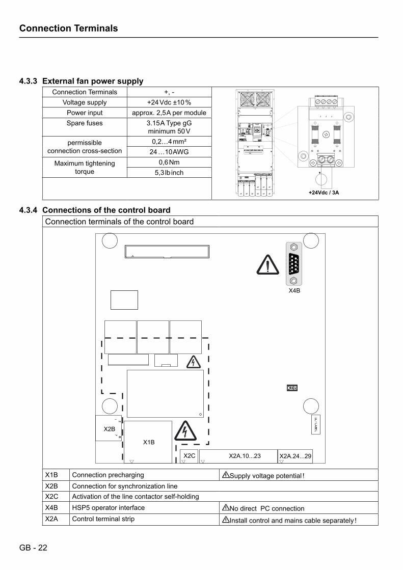
4.3.3 External fan power supplyConnection Terminals +, -
+
+24Vdc / 3A
Voltage supply +24 Vdc ±10 %Power input approx. 2,5 A per moduleSpare fuses 3.15 A Type gG
minimum 50 V
permissible connection cross-section
0,2…4 mm²24 …10 AWG
Maximum tightening torque
0,6 Nm5,3 lb inch
4.3.4 Connections of the control boardConnection terminals of the control board
X2A.10...23 X2A.24...29
X1B
X2C
X2B
X4B5
43
21
98
76
54
32
1
98
76
X1B Connection precharging Supplyvoltagepotential!X2B Connection for synchronization lineX2C Activation of the line contactor self-holdingX4B HSP5 operator interface No direct PC connectionX2A Control terminal strip Installcontrolandmainscableseparately!
GB - 23
Connection Terminals
4.3.5 Connection of the synchronization unit
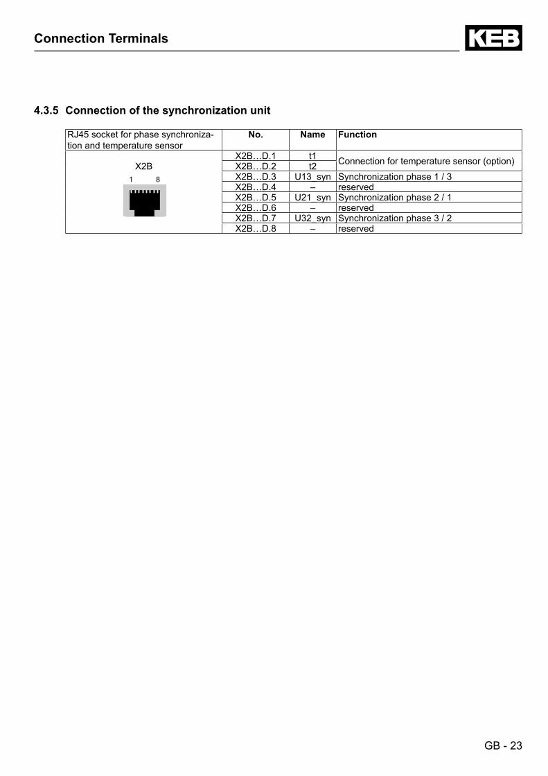
RJ45 socket for phase synchroniza-tion and temperature sensor
No. Name Function
X2BX2B…D.1 t1 Connectionfortemperaturesensor(option)X2B…D.2 t2
1 8 X2B…D.3 U13_syn Synchronization phase 1 / 3X2B…D.4 – reservedX2B…D.5 U21_syn Synchronization phase 2 / 1X2B…D.6 – reservedX2B…D.7 U32_syn Synchronization phase 3 / 2X2B…D.8 – reserved
GB - 24
Connection Power Unit
4.4 Connection Power Unit R6
4.4.1 Supplyandregenrativeoperationatinvertercurrent≤currentofoneCOMBIVERTR6-S
N L
L2.1 L1.1
L3.1
++
- -
xx
xx
PE
W V U
L3.2 L2.2 L1.2
L3.2 L2.2 L1.2
2425
21 22
12 17
43 44
13 14
L1 L2 L3
L1 L2 L3
L1’ L2’ L3’
PE
L2 L1
13/K214/K2
A2 A1
X1A
X2C
X1BX1B
S1
S2
F1
F2
K1
HF
A1
DR
H1 H1
F4 G2
G1
M
X2B L3
X2B L2 L1
X2A
F3
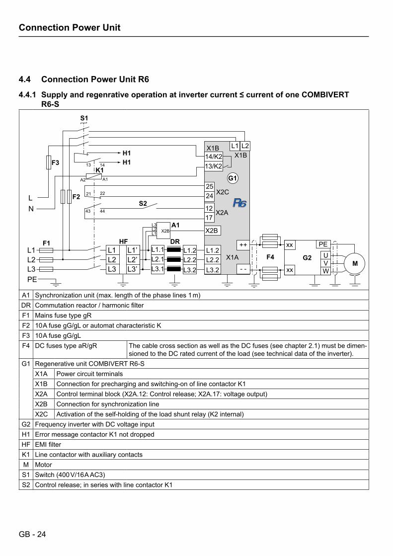
A1 Synchronizationunit(max.lengthofthephaselines1m)DR Commutationreactor/harmonicfilterF1 Mains fuse type gRF2 10AfusegG/gLorautomatcharacteristicKF3 10AfusegG/gLF4 DC fuses type aR/gR ThecablecrosssectionaswellastheDCfuses(seechapter2.1)mustbedimen-
sionedtotheDCratedcurrentoftheload(seetechnicaldataoftheinverter).G1 Regenerative unit COMBIVERT R6-S
X1A Power circuit terminalsX1B Connection for precharging and switching-on of line contactor K1X2A Controlterminalblock(X2A.12:Controlrelease;X2A.17:voltageoutput)X2B Connection for synchronization lineX2C Activationoftheself-holdingoftheloadshuntrelay(K2internal)
G2 Frequency inverter with DC voltage inputH1 Error message contactor K1 not droppedHF EMIfilterK1 LinecontactorwithauxiliarycontactsM MotorS1 Switch(400V/16AAC3)S2 Control release; in series with line contactor K1
GB - 25
Connection Power Unit
4.4.2 Supplyandregenrativeoperationatinvertercurrents≤currentofoneCOMBIVERTR6-S
N L
L2.1 L1.1
L3.1
++
- - L3.2 L2.2 L1.2
L3.2 L2.2 L1.2
2425
21 22
12 17
43 44
13 14
L1 L2 L3
L1 L2 L3
L1’ L2’ L3’
PE
L2 L1
13/K214/K2
A2 A1
X1A
X2C
X1BX1B
S1
F1
F2
K1
HF
A1
DR
H1
S2
H1
G1
X2B L3
X2B L2 L1
X2A
xx xx xx xx
PE U V W PE U V W
F4 F4
G2 G2
M M
F3
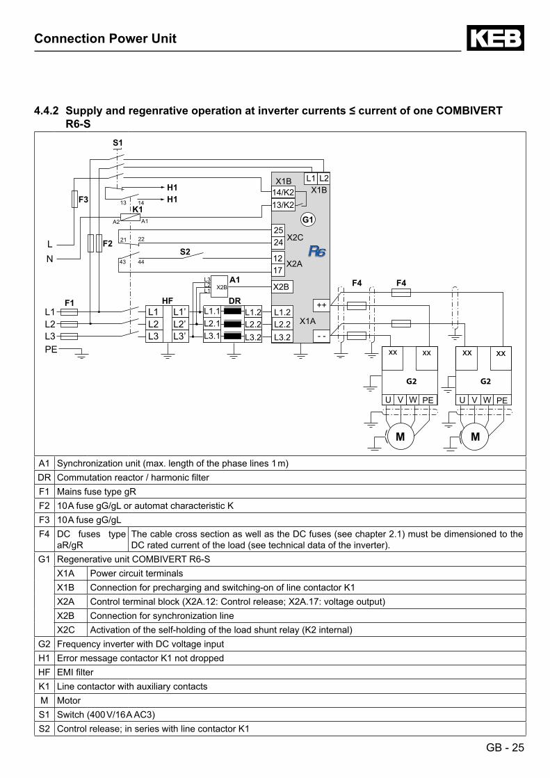
A1 Synchronizationunit(max.lengthofthephaselines1m)DR Commutationreactor/harmonicfilterF1 Mains fuse type gRF2 10AfusegG/gLorautomatcharacteristicKF3 10AfusegG/gLF4 DC fuses type
aR/gRThecablecrosssectionaswellastheDCfuses(seechapter2.1)mustbedimensionedtotheDCratedcurrentoftheload(seetechnicaldataoftheinverter).
G1 Regenerative unit COMBIVERT R6-SX1A Power circuit terminalsX1B Connection for precharging and switching-on of line contactor K1X2A Controlterminalblock(X2A.12:Controlrelease;X2A.17:voltageoutput)X2B Connection for synchronization lineX2C Activationoftheself-holdingoftheloadshuntrelay(K2internal)
G2 Frequency inverter with DC voltage inputH1 Error message contactor K1 not droppedHF EMIfilterK1 LinecontactorwithauxiliarycontactsM MotorS1 Switch(400V/16AAC3)S2 Control release; in series with line contactor K1
GB - 26
Connection Power Unit
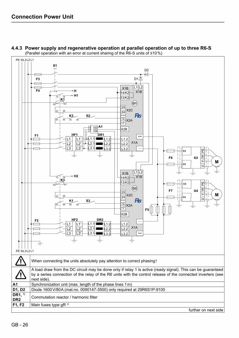
4.4.3 Power supply and regenerative operation at parallel operation of up to three R6-S(ParalleloperationwithanerroratcurrentsharingoftheR6-Sunitsof≤10%)
N
L2.1L1.1
L3.1
++
- -L3.2L2.2L1.2
L3.2L2.2L1.2
2425
21 22
1217
43 44 33 34
13 14
L1L2L3
L1L2L3
L1’L2’L3’
L2L1
13/K214/K2
A2 A1
X1A
X2C
X1BX1B
S1
F1
F3
K1
HF1
A1
DR1
H
S2K3
33 34K1
H1
G1
X2BL3
X2BX2CX2DL2
L1
X2A
xx
xxP
EU
VWF7
F5
G4M
F4
L2.1L1.1
L3.1
- -
++L3.2L2.2L1.2
L3.2L2.2L1.2
2425
21 22
1217
43 44
13 14
L1L2L3
L1’L2’L3’
PE
L2L1
13/K214/K2
A2 A1
X1A
X2C
X1BX1B
F2
K3
HF2 DR2
S3
H2
G2
X2B
X2A
xx
xx
PE
UV
WF6 G3M
N L1L2L3PE
D1
D2
Whenconnectingtheunitsabsolutelypayattentiontocorrectphasing!
AloaddrawfromtheDCcircuitmaybedoneonlyifrelay1isactive(readysignal).ThiscanbeguaranteedbyaseriesconnectionoftherelayoftheR6unitswiththecontrolreleaseoftheconnectedinverters(seenextside).
A1 Synchronizationunit(max.lengthofthephaselines1m)D1, D2 Diode1600V/80A(mat.no.0090147-3500)onlyrequiredat29R6S1P-9100DR1, 1)
DR2 Commutationreactor/harmonicfilter
F1, F2 Main fuses type gR 2)further on next side
GB - 27
Connection Power Unit
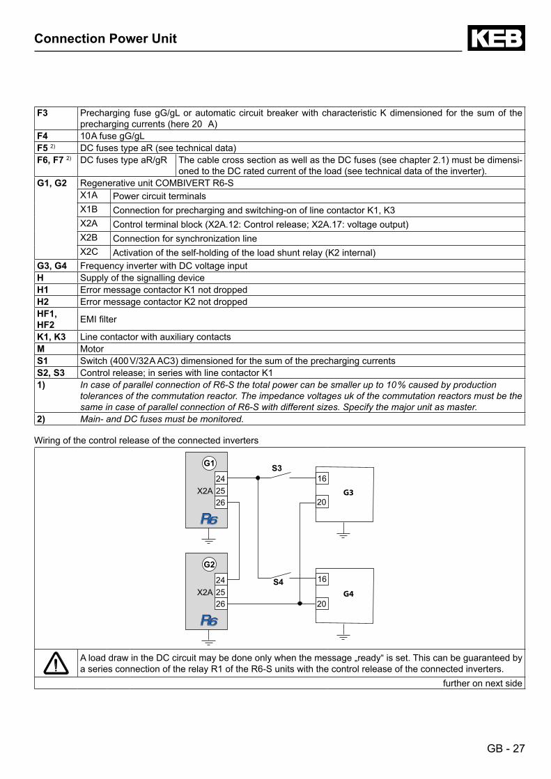
F3 Precharging fusegG/gLorautomaticcircuitbreakerwithcharacteristicKdimensioned for thesumof theprechargingcurrents(here20A)
F4 10AfusegG/gLF5 2) DCfusestypeaR(seetechnicaldata)F6, F7 2) DC fuses type aR/gR ThecablecrosssectionaswellastheDCfuses(seechapter2.1)mustbedimensi-
onedtotheDCratedcurrentoftheload(seetechnicaldataoftheinverter).G1, G2 Regenerative unit COMBIVERT R6-S
X1A Power circuit terminalsX1B Connection for precharging and switching-on of line contactor K1, K3X2A Controlterminalblock(X2A.12:Controlrelease;X2A.17:voltageoutput)X2B Connection for synchronization lineX2C Activationoftheself-holdingoftheloadshuntrelay(K2internal)
G3, G4 Frequency inverter with DC voltage inputH Supply of the signalling deviceH1 Error message contactor K1 not droppedH2 Error message contactor K2 not droppedHF1,HF2 EMIfilter
K1, K3 LinecontactorwithauxiliarycontactsM MotorS1 Switch(400V/32AAC3)dimensionedforthesumoftheprechargingcurrentsS2, S3 Control release; in series with line contactor K11) In case of parallel connection of R6‑S the total power can be smaller up to 10 % caused by production
tolerances of the commutation reactor. The impedance voltages uk of the commutation reactors must be the same in case of parallel connection of R6‑S with different sizes. Specify the major unit as master.
2) Main‑ and DC fuses must be monitored.
Wiring of the control release of the connected inverters
16
20
G42524
26
S4
G2
X2A
2524
26
S3G1
X2A G3
16
20
AloaddrawintheDCcircuitmaybedoneonlywhenthemessage„ready“isset.Thiscanbeguaranteedbya series connection of the relay R1 of the R6-S units with the control release of the connected inverters.
further on next side
GB - 28
Connection Power Unit
G1, G2 Regenerative unit COMBIVERT R6-SX2A Control terminal strip
24 Relay 1 / NO contactReady for operation relay25 Relay 1 / NC contact
26 Relay 1 / switching contactG3, G4 Frequency inverter COMBIVERT F5
X2A Control terminal strip16 Control release This terminal assignment refers only to one
COMBIVERT F520 24 V-outputS3, S4 Control release for COMBIVERT F5
GB - 29
Connection Power Unit
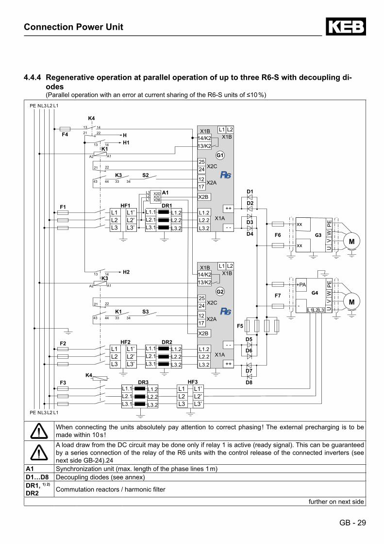
4.4.4 Regenerative operation at parallel operation of up to three R6-S with decoupling di-odes(ParalleloperationwithanerroratcurrentsharingoftheR6-Sunitsof≤10%)
N
L2.1L1.1
L3.1
++
- -L3.2L2.2L1.2
L3.2L2.2L1.2
2425
21 22
1217
43 44 33 34
13 14
L1L2L3
L1L2L3
L1’L2’L3’
L2L1
13/K214/K2
A2 A1
X1A
X2C
X1BX1B
K4
F1
K1
HF1
A1
DR1
H
S2K3
33 34K1
H1
G1
X2BL3
X2BX2CX2DL2
L1
X2A
+PA
-
PE
UV
WF7
F5
G4
M
F4
- -
++L3.2L2.2L1.2
2425
21 22
1217
43 44
13 14
L1L2L3
L1’L2’L3’
PE
L2L1
13/K214/K2
A2 A1
X1A
X2C
X1BX1B
F2
K3
HF2
L2.1L1.1
L3.1 L3.2L2.2L1.2
DR2
S3
H2
G2
X2B
X2A
xx
xx
PE
UV
WF6 G3M
F3
N L1L2L3PE
D2
D1
D7
D8
D5
D6
D4
D3
L1L2L3
L2.1L1.1
L3.1 L3.2L2.2L1.2
DR3L1L2L3
L1’L2’L3’
HF3K4
13 1421 22
Whenconnecting theunitsabsolutelypayattention tocorrectphasing!Theexternalprecharging is tobemadewithin10s!AloaddrawfromtheDCcircuitmaybedoneonlyifrelay1isactive(readysignal).ThiscanbeguaranteedbyaseriesconnectionoftherelayoftheR6unitswiththecontrolreleaseoftheconnectedinverters(seenextsideGB-24).24
A1 Synchronizationunit(max.lengthofthephaselines1m)D1…D8 Decouplingdiodes(seeannex)DR1, 1) 2)
DR2 Commutationreactors/harmonicfilter
further on next side
GB - 30
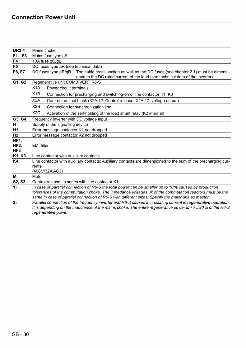
Connection Power Unit
DR3 2) Mains chokeF1…F3 Mains fuse type gRF4 10AfusegG/gLF5 DCfusestypeaR(seetechnicaldata)F6, F7 DC fuses type aR/gR ThecablecrosssectionaswellastheDCfuses(seechapter2.1)mustbedimensi-
onedtotheDCratedcurrentoftheload(seetechnicaldataoftheinverter).G1, G2 Regenerative unit COMBIVERT R6-S
X1A Power circuit terminalsX1B Connection for precharging and switching-on of line contactor K1, K3X2A Controlterminalblock(X2A.12:Controlrelease;X2A.17:voltageoutput)X2B Connection for synchronization lineX2C Activationoftheself-holdingoftheloadshuntrelay(K2internal)
G3, G4 Frequency inverter with DC voltage inputH Supply of the signalling deviceH1 Error message contactor K1 not droppedH2 Error message contactor K2 not droppedHF1, HF2,HF3
EMIfilter
K1, K3 LinecontactorwithauxiliarycontactsK4 Linecontactorwithauxiliarycontacts;Auxiliarycontactsaredimensionedtothesumoftheprechargingcur-
rents(400V/32AAC3)
M MotorS2, S3 Control release; in series with line contactor K11) In case of parallel connection of R6‑S the total power can be smaller up to 10 % caused by production
tolerances of the commutation choke. The impedance voltages uk of the commutation reactors must be the same in case of parallel connection of R6‑S with different sizes. Specify the major unit as master.
2) Parallel connection of the frequency inverter and R6‑S causes a circulating current in regenerative operation. It is depending on the inductance of the mains choke. The entire regenerative power is 75... 90 % of the R6‑S regenerative power.
GB - 31
Connection of the Control Board
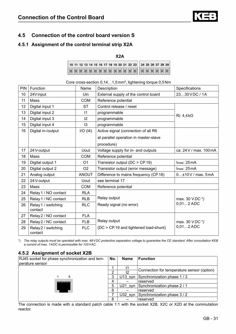
4.5 Connection of the control board version S
4.5.1 Assignment of the control terminal strip X2A
X2A
Core cross-section 0,14…1,5 mm², tightening torque 0,5 NmPIN Function Name Description Specifications10 24V input Uin External supply of the control board 23…30 V DC / 1 A11 Mass COM Reference potential12 Digital input 1 ST Control release / reset
Ri:4,4kΩ13 Digital input 2 I1 programmable14 Digital input 3 I2 programmable15 Digital input 4 I3 programmable16 Digital in-/output I/O(I4) Activesignal(connectionofallR6
at parallel operation in master-slave
procedure)17 24 V-output Uout Voltage supply for in- and outputs ca. 24 V / max. 100 mA18 Mass COM Reference potential19 Digital output 1 O1 Transistoroutput(DC>CP.19) Imax: 25 mA20 Digital output 2 O2 Transistoroutput(errormessage) Imax: 25 mA21 Analog output ANOUT Differencetomainsfrequency(CP.18) 0…±10 V / max. 5 mA22 24 V-output Uout see terminal 1723 Mass COM Reference potential24 Relay 1 / NO contact RLA
Relay output
Readysignal(noerror)max. 30 V DC *)0,01…2 A DC
25 Relay 1 / NC contact RLB26 Relay 1 / switching
contactRLC
27 Relay 2 / NO contact FLARelay output
(DC>CP.19andtightenedload-shunt)max. 30 V DC *)0,01…2 A DC
28 Relay 2 / NC contact FLB29 Relay 2 / switching
contactFLC
*) The relay outputs must be operated with max. 48 V DC protective separation voltage to guarantee the CE standard. After consultation KEB a current of max. 1 A DC is permissible for 120 V AC.
4.5.2 Assignment of socket X2BRJ45 socket for phase synchronization and tem-perature sensor
No. Name Function
1 8
1 t1 Connectionfortemperaturesensor(option)2 t23 U13_syn Synchronization phase 1 / 34 – reserved5 U21_syn Synchronization phase 2 / 16 – reserved7 U32_syn Synchronization phase 3 / 28 – reserved
The connection is made with a standard patch cable 1:1 with the socket X2B, X2C or X2D at the commutation reactor.
10 11 12 13 14 15 16 17 18 19 20 21 22 23 24 25 26 27 28 29
GB - 32
Connection of the Control Board
U
X2A 10 11 12 13 14 15 16 17 18
16
18 19 20 21 22 23
24 25 26 27 28 29
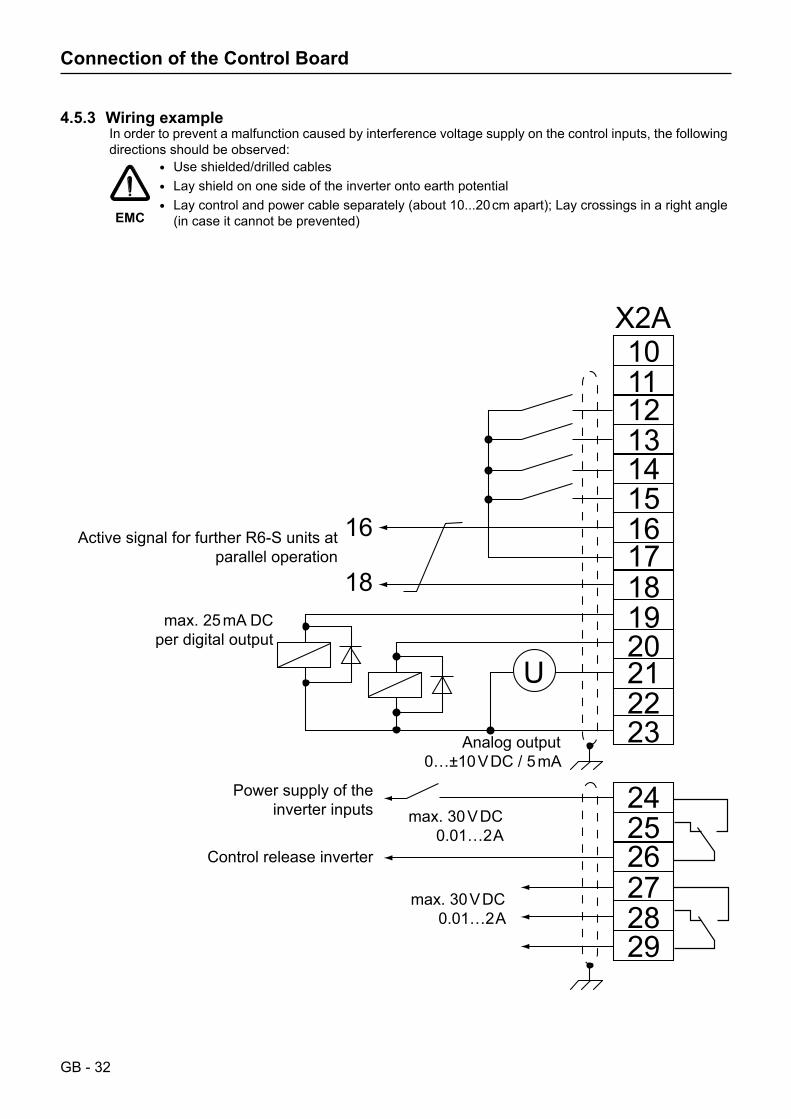
4.5.3 Wiring exampleIn order to prevent a malfunction caused by interference voltage supply on the control inputs, the following directions should be observed:
EMC
• Use shielded/drilled cables• Layshieldononesideoftheinverterontoearthpotential• Laycontrolandpowercableseparately(about10...20 cmapart);Laycrossingsinarightangle(incaseitcannotbeprevented)
max. 25 mA DC per digital output
Analog output0…±10 V DC / 5 mA
max. 30 V DC0.01…2 A
max. 30 V DC0.01…2 A
Active signal for further R6-S units at parallel operation
Power supply of the inverter inputs
Control release inverter
GB - 33
Installation and Connection
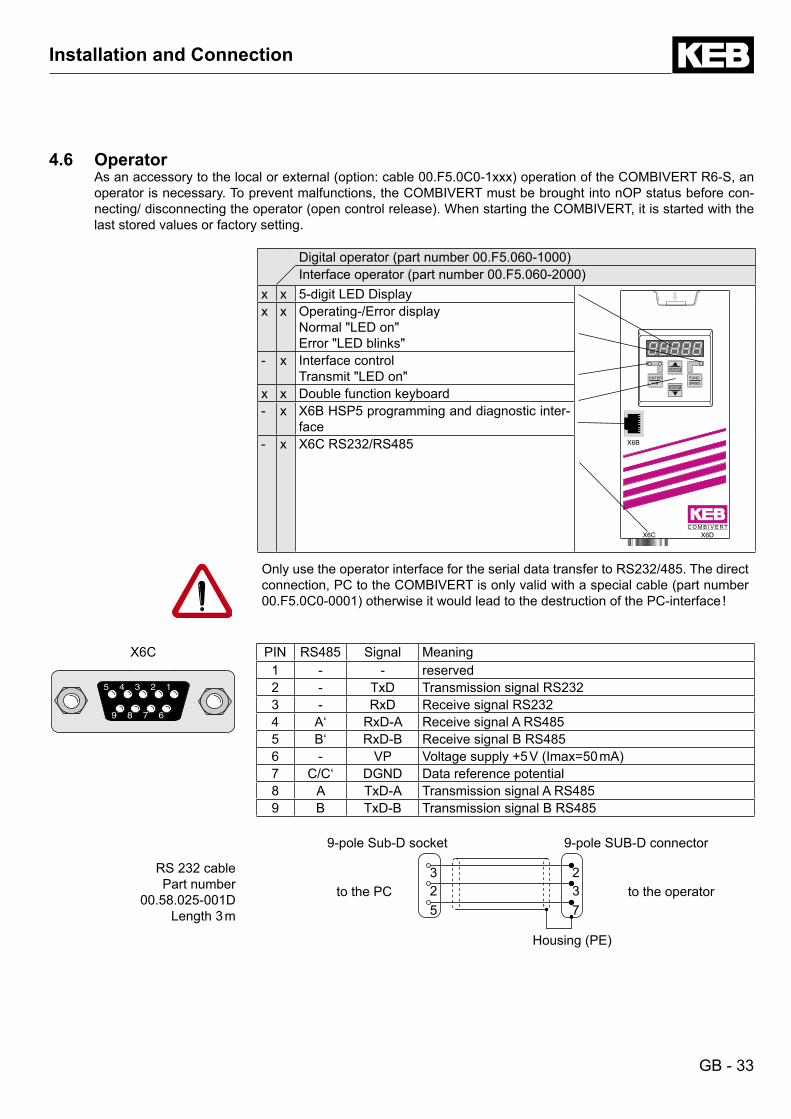
4.6 OperatorAsanaccessorytothelocalorexternal(option:cable00.F5.0C0-1xxx)operationoftheCOMBIVERTR6-S,anoperator is necessary. To prevent malfunctions, the COMBIVERT must be brought into nOP status before con-necting/disconnectingtheoperator(opencontrolrelease).WhenstartingtheCOMBIVERT,itisstartedwiththelast stored values or factory setting.
Digitaloperator(partnumber00.F5.060-1000)Interfaceoperator(partnumber00.F5.060-2000)
x x 5-digitLEDDisplay
START
FUNC.
SPEED
ENTER
F/RSTOP
C O M B I V E R T
X6C X6D
X6B
x x Operating-/Error displayNormal"LEDon"Error"LEDblinks"
- x Interface controlTransmit"LEDon"
x x Double function keyboard- x X6B HSP5 programming and diagnostic inter-
face- x X6C RS232/RS485
Only use the operator interface for the serial data transfer to RS232/485. The direct connection,PCtotheCOMBIVERTisonlyvalidwithaspecialcable(partnumber00.F5.0C0-0001)otherwiseitwouldleadtothedestructionofthePC-interface!
X6C PIN RS485 Signal Meaning5 4 3 2 1
9 8 7 6
5 4 3 2 1
9 8 7 6
1 - - reserved2 - TxD Transmission signal RS2323 - RxD Receive signal RS2324 A‘ RxD-A Receive signal A RS4855 B‘ RxD-B Receive signal B RS4856 - VP Voltagesupply+5V(Imax=50mA)7 C/C‘ DGND Data reference potential8 A TxD-A Transmission signal A RS4859 B TxD-B Transmission signal B RS485
RS 232 cablePart number
00.58.025-001DLength3m
9-pole Sub-D socket 9-pole SUB-D connector
to the PC325
237
to the operator
Housing(PE)
GB - 34
Operation of the Unit
5. Operation of the Unit5.1 Keyboard
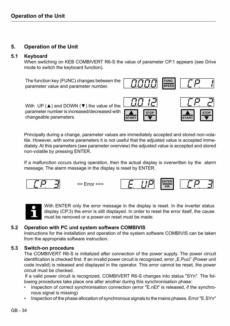
WhenswitchingonKEBCOMBIVERTR6-SthevalueofparameterCP.1appears(seeDrivemodetoswitchthekeyboardfunction).
Thefunctionkey(FUNC)changesbetweentheparameter value and parameter number.
WithUP()andDOWN()thevalueoftheparameter number is increased/decreased with changeable parameters.
Principally during a change, parameter values are immediately accepted and stored non-vola-tile. However, with some parameters it is not useful that the adjusted value is accepted imme-diately.Atthisparameters(seeparameteroverview)theadjustedvalueisacceptedandstorednon-volatile by pressing ENTER.
If a malfunction occurs during operation, then the actual display is overwritten by the alarm message. The alarm message in the display is reset by ENTER.
==Error==>
With ENTER only the error message in the display is reset. In the inverter status display(CP.3)theerrorisstilldisplayed.Inordertoresettheerroritself,thecausemust be removed or a power-on reset must be made.
5.2 Operation with PC und system software COMBIVISInstructions for the installation and operation of the system software COMBIVIS can be taken from the appropriate software instruction.
5.3 Switch-on procedureThe COMBIVERT R6-S is initialized after connection of the power supply. The power circuit identificationischeckedfirst.Ifaninvalidpowercircuitisrecognized,error„E.Puci”(Powerunitcodeinvalid)isreleasedanddisplayedintheoperator.Thiserrorcannotbereset,thepowercircuit must be checked. If a valid power circuit is recognized, COMBIVERT R6-S changes into status "SYn". The fol-lowing procedures take place one after another during this synchronisation phase:
Inspectionofcorrectsynchronisationconnection(error"E.nEt"isreleased,ifthesynchro-•noussignalismissing)Inspection of the phase allocation of synchronous signals to the mains phases. Error "E.SYn" •
GB - 35
Operation of the Unit
is released if a phase is missing or in case of phase allocation failure.
The actual mains frequency is determined and the correct connection of the COMBIVERT R6-Sissecuredaftersuccessfulsynchronisation. If thecontrolrelease(terminalST) isset,theCOMBIVERTR6-Sstartsindependentlywiththespecifiedoperation.Dependingwhetherregenerativerequirementisavailable,theCOMBIVERTR6-Sisinstatus„rEGEn”or„Stb”.
Status „Stb“COMBIVERT R6-S detects a typical voltage level in the DC link circuit of the connected fre-quencyinverter(motoroperation)andkeepsthemodulationsignalsoftheregenerativeunitdeactivated.
Status „rEGEn” The modulation signals are activated and the unit changes into regenerative operation on ex-ceedingtheDCvoltageintheDClink(CP.09)morethan103%oftheinputvoltage.Furtherthe regenerative unit is switched active, if regenerative operation is requested by an additional installedCOMBIVERTR6-Sinthesystem(master/slaveoperation).
GB - 36
Operation of the Unit
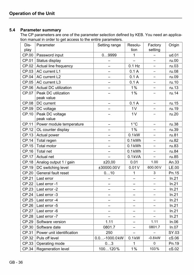
5.4 Parameter summaryThe CP parameters are one of the parameter selection defined by KEB. You need an applica-tion manual in order to get access to the entire parameters.
Dis-play
Parameter Setting range Resolu-tion
Factory setting
Origin
CP.00 Password input 0…9999 1 – ud.01CP.01 Status display – – – ru.00CP.02 Actual line frequency – 0.1 Hz – ru.03CP.03 AC current L1 – 0.1 A – ru.08CP.04 AC current L2 – 0.1 A – ru.09CP.05 AC current L3 – 0.1 A – ru.10CP.06 Actual DC utilization – 1 % – ru.13CP.07 Peak DC utilization
peak value– 1 % – ru.14
CP.08 DC current – 0.1 A – ru.15CP.09 DC voltage – 1 V – ru.19CP.10 Peak DC voltage
peak value– 1 V – ru.20
CP.11 Power module temperature – 1 °C – ru.38CP.12 OL counter display – 1 % – ru.39CP.13 Actual power – 0.1 kW – ru.81CP.14 Total regen – 0.1 kWh – ru.82CP.15 Total motor – 0.1 kWh – ru.83CP.16 Total net – 0.1 kWh – ru.84CP.17 Actual net – 0.1 kVA – ru.85CP.18 Analog output 1 / gain ±20,00 0.01 1.00 An.33CP.19 DC switching level ±30000.00 V 0.01 V 600.00 V LE.00CP.20 General fault reset 0…10 1 3 Pn.15CP.21 Last error – – – In.21CP.22 Last error -1 – – – In.21CP.23 Last error -2 – – – In.21CP.24 Last error -3 – – – In.21CP.25 Last error -4 – – – In.21CP.26 Last error -5 – – – In.21CP.27 Last error -6 – – – In.21CP.28 Last error -7 – – – In.21CP.29 Software version 1.11 – 1.11 In.06CP.30 Software date 0801.7 – 0801.7 In.07CP.31 Power unit identification 250 – – SY.03CP.32 Puls off level 0.0…-1000.0 kW 0.1 kW -0.8 kW cS.06CP.33 Operating mode 0…3 1 0 Pn.19CP.34 Regeneration level 100…120 % 1 % 103 % cS.02
GB - 37
Operation of the Unit
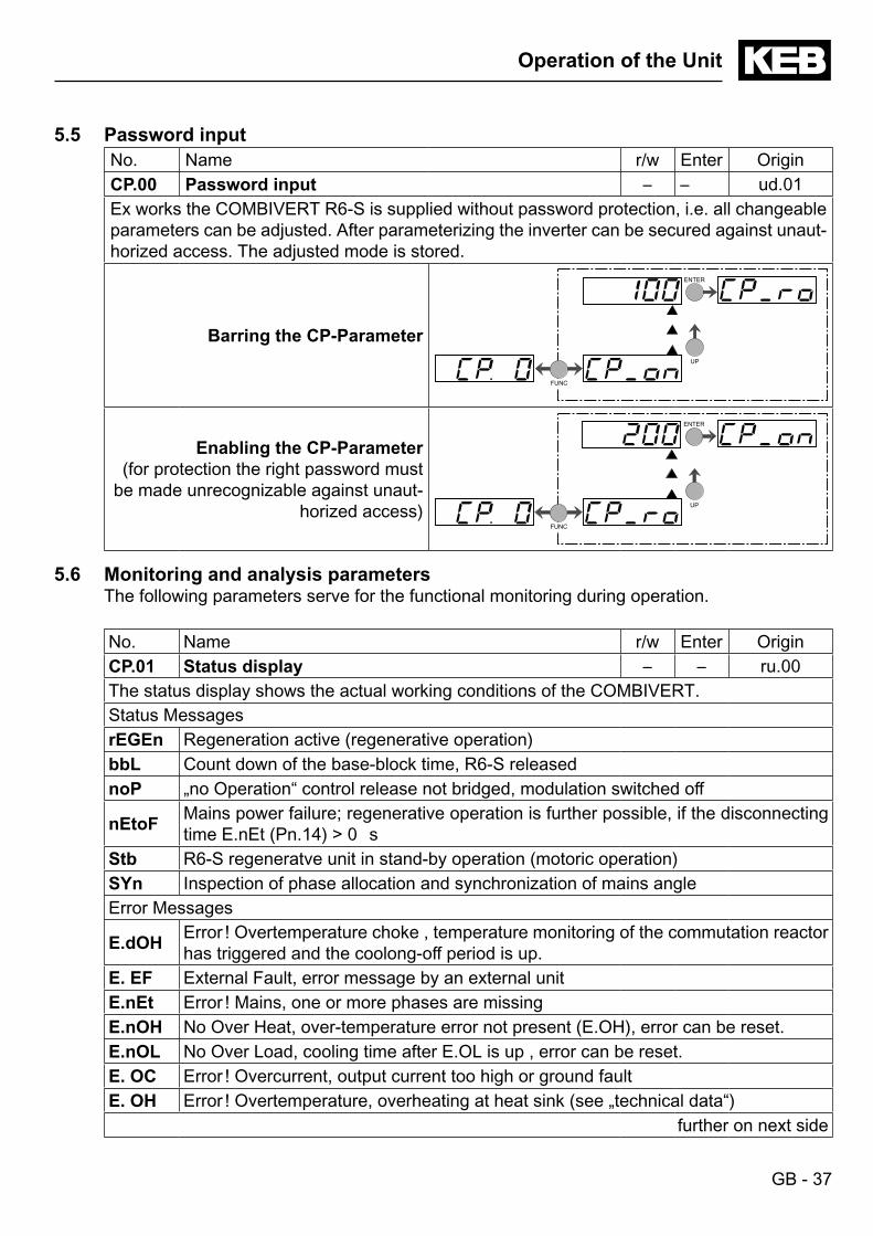
5.5 Password inputNo. Name r/w Enter OriginCP.00 Password input – – ud.01Ex works the COMBIVERT R6-S is supplied without password protection, i.e. all changeable parameters can be adjusted. After parameterizing the inverter can be secured against unaut-horized access. The adjusted mode is stored.
Barring the CP-Parameter
FUNC
ENTER
UP
Enabling the CP-Parameter(for protection the right password must
be made unrecognizable against unaut-horized access)
FUNC
ENTER
UP
5.6 Monitoring and analysis parametersThe following parameters serve for the functional monitoring during operation.
No. Name r/w Enter OriginCP.01 Status display – – ru.00The status display shows the actual working conditions of the COMBIVERT.Status MessagesrEGEn Regeneration active (regenerative operation)bbL Count down of the base-block time, R6-S releasednoP „no Operation“ control release not bridged, modulation switched off
nEtoF Mains power failure; regenerative operation is further possible, if the disconnecting time E.nEt (Pn.14) > 0 s
Stb R6-S regeneratve unit in stand-by operation (motoric operation)SYn Inspection of phase allocation and synchronization of mains angleError Messages
E.dOH Error ! Overtemperature choke , temperature monitoring of the commutation reactor has triggered and the coolong-off period is up.
E. EF External Fault, error message by an external unitE.nEt Error ! Mains, one or more phases are missingE.nOH No Over Heat, over-temperature error not present (E.OH), error can be reset.E.nOL No Over Load, cooling time after E.OL is up , error can be reset.E. OC Error ! Overcurrent, output current too high or ground faultE. OH Error ! Overtemperature, overheating at heat sink (see „technical data“)
further on next side
GB - 38
Operation of the Unit
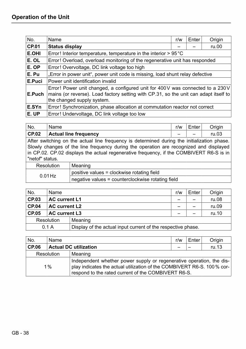
No. Name r/w Enter OriginCP.01 Status display – – ru.00E.OHI Error ! Interior temperature, temperature in the interior > 95 °CE. OL Error ! Overload, overload monitoring of the regenerative unit has respondedE. OP Error ! Overvoltage, DC link voltage too highE. Pu „Error in power unit“, power unit code is missing, load shunt relay defectiveE.Puci Power unit identification invalid
E.PuchError ! Power unit changed, a configured unit for 400 V was connected to a 230 V mains (or reverse). Load factory setting with CP.31, so the unit can adapt itself to the changed supply system.
E.SYn Error ! Synchronization, phase allocation at commutation reactor not correctE. UP Error ! Undervoltage, DC link voltage too low
No. Name r/w Enter OriginCP.02 Actual line frequency – – ru.03After switching on the actual line frequency is determined during the initialization phase. Slowly changes of the line frequency during the operation are recognized and displayed in CP.02. CP.02 displays the actual regenerative frequency, if the COMBIVERT R6-S is in "netof" status.
Resolution Meaning
0.01 Hz positive values = clockwise rotating fieldnegative values = counterclockwise rotating field
No. Name r/w Enter OriginCP.03 AC current L1 – – ru.08CP.04 AC current L2 – – ru.09CP.05 AC current L3 – – ru.10
Resolution Meaning0.1 A Display of the actual input current of the respective phase.
No. Name r/w Enter OriginCP.06 Actual DC utilization – – ru.13
Resolution Meaning
1 %Independent whether power supply or regenerative operation, the dis-play indicates the actual utilization of the COMBIVERT R6-S. 100 % cor-respond to the rated current of the COMBIVERT R6-S.
GB - 39
Operation of the Unit
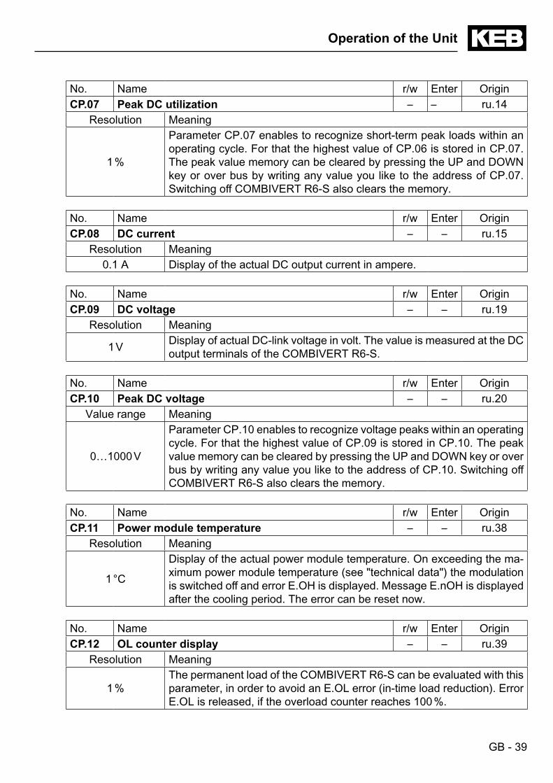
No. Name r/w Enter OriginCP.07 Peak DC utilization – – ru.14
Resolution Meaning
1 %
Parameter CP.07 enables to recognize short-term peak loads within an operating cycle. For that the highest value of CP.06 is stored in CP.07. The peak value memory can be cleared by pressing the UP and DOWN key or over bus by writing any value you like to the address of CP.07. Switching off COMBIVERT R6-S also clears the memory.
No. Name r/w Enter OriginCP.08 DC current – – ru.15
Resolution Meaning0.1 A Display of the actual DC output current in ampere.
No. Name r/w Enter OriginCP.09 DC voltage – – ru.19
Resolution Meaning
1 V Display of actual DC-link voltage in volt. The value is measured at the DC output terminals of the COMBIVERT R6-S.
No. Name r/w Enter OriginCP.10 Peak DC voltage – – ru.20
Value range Meaning
0…1000 V
Parameter CP.10 enables to recognize voltage peaks within an operating cycle. For that the highest value of CP.09 is stored in CP.10. The peak value memory can be cleared by pressing the UP and DOWN key or over bus by writing any value you like to the address of CP.10. Switching off COMBIVERT R6-S also clears the memory.
No. Name r/w Enter OriginCP.11 Power module temperature – – ru.38
Resolution Meaning
1 °C
Display of the actual power module temperature. On exceeding the ma-ximum power module temperature (see "technical data") the modulation is switched off and error E.OH is displayed. Message E.nOH is displayed after the cooling period. The error can be reset now.
No. Name r/w Enter OriginCP.12 OL counter display – – ru.39
Resolution Meaning
1 %The permanent load of the COMBIVERT R6-S can be evaluated with this parameter, in order to avoid an E.OL error (in-time load reduction). Error E.OL is released, if the overload counter reaches 100 %.
GB - 40
Operation of the Unit
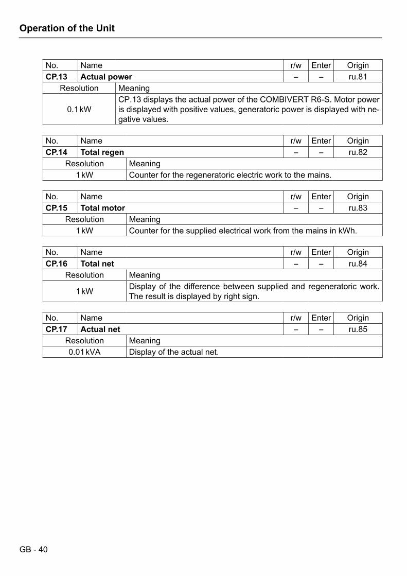
No. Name r/w Enter OriginCP.13 Actual power – – ru.81
Resolution Meaning
0.1 kWCP.13 displays the actual power of the COMBIVERT R6-S. Motor power is displayed with positive values, generatoric power is displayed with ne-gative values.
No. Name r/w Enter OriginCP.14 Total regen – – ru.82
Resolution Meaning1 kW Counter for the regeneratoric electric work to the mains.
No. Name r/w Enter OriginCP.15 Total motor – – ru.83
Resolution Meaning1 kW Counter for the supplied electrical work from the mains in kWh.
No. Name r/w Enter OriginCP.16 Total net – – ru.84
Resolution Meaning
1 kW Display of the difference between supplied and regeneratoric work. The result is displayed by right sign.
No. Name r/w Enter OriginCP.17 Actual net – – ru.85
Resolution Meaning0.01 kVA Display of the actual net.
GB - 41
Operation of the Unit
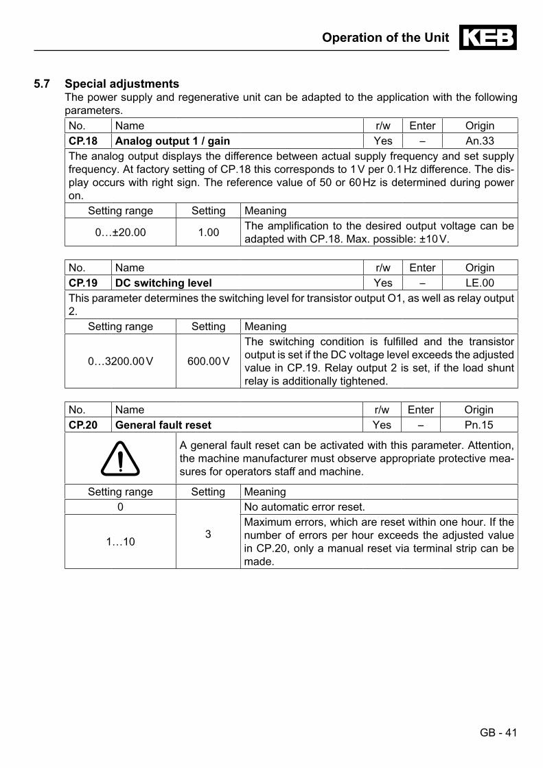
5.7 Special adjustmentsThe power supply and regenerative unit can be adapted to the application with the following parameters.No. Name r/w Enter OriginCP.18 Analog output 1 / gain Yes – An.33The analog output displays the difference between actual supply frequency and set supply frequency. At factory setting of CP.18 this corresponds to 1 V per 0.1 Hz difference. The dis-play occurs with right sign. The reference value of 50 or 60 Hz is determined during power on.
Setting range Setting Meaning
0…±20.00 1.00 The amplification to the desired output voltage can be adapted with CP.18. Max. possible: ±10 V.
No. Name r/w Enter OriginCP.19 DC switching level Yes – LE.00This parameter determines the switching level for transistor output O1, as well as relay output 2.
Setting range Setting Meaning
0…3200.00 V 600.00 V
The switching condition is fulfilled and the transistor output is set if the DC voltage level exceeds the adjusted value in CP.19. Relay output 2 is set, if the load shunt relay is additionally tightened.
No. Name r/w Enter OriginCP.20 General fault reset Yes – Pn.15
A general fault reset can be activated with this parameter. Attention, the machine manufacturer must observe appropriate protective mea-sures for operators staff and machine.
Setting range Setting Meaning0
3
No automatic error reset.
1…10
Maximum errors, which are reset within one hour. If the number of errors per hour exceeds the adjusted value in CP.20, only a manual reset via terminal strip can be made.
GB - 42
Operation of the Unit
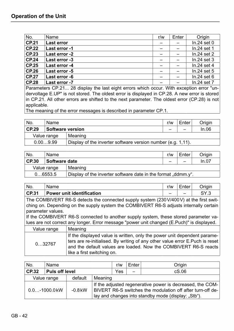
No. Name r/w Enter OriginCP.21 Last error – – In.24 set 0CP.22 Last error -1 – – In.24 set 1CP.23 Last error -2 – – In.24 set 2CP.24 Last error -3 – – In.24 set 3CP.25 Last error -4 – – In.24 set 4CP.26 Last error -5 – – In.24 set 5CP.27 Last error -6 – – In.24 set 6CP.28 Last error -7 – – In.24 set 7Parameters CP.21... 28 display the last eight errors which occur. With exception error "un-dervoltage E.UP" is not stored. The oldest error is displayed in CP.28. A new error is stored in CP.21. All other errors are shifted to the next parameter. The oldest error (CP.28) is not applicable.The meaning of the error messages is described in parameter CP.1.
No. Name r/w Enter OriginCP.29 Software version – – In.06
Value range Meaning0.00…9.99 Display of the inverter software version number (e.g. 1,11).
No. Name r/w Enter OriginCP.30 Software date – – In.07
Value range Meaning0…6553.5 Display of the inverter software date in the format „ddmm.y“.
No. Name r/w Enter OriginCP.31 Powerunitidentification – – SY.3The COMBIVERT R6-S detects the connected supply system (230 V/400 V) at the first swit-ching on. Depending on the supply system the COMBIVERT R6-S adjusts internally certain parameter values.If the COMBIVERT R6-S connected to another supply system, these stored parameter va-lues are not correct any longer. Error message "power unit changed (E.Puch)" is displayed.
Value range Meaning
0…32767
If the displayed value is written, only the power unit dependent parame-ters are re-initialised. By writing of any other value error E.Puch is reset and the default values are loaded. Now the COMBIVERT R6-S reacts like a first switching on.
No. Name r/w Enter OriginCP.32 Puls off level Yes – cS.06
Value range default Meaning
0.0…-1000.0 kW -0.8 kWIf the adjusted regenerative power is decreased, the COM-BIVERT R6-S switches the modulation off after turn-off de-lay and changes into standby mode (display: „Stb“).
GB - 43
Operation of the Unit
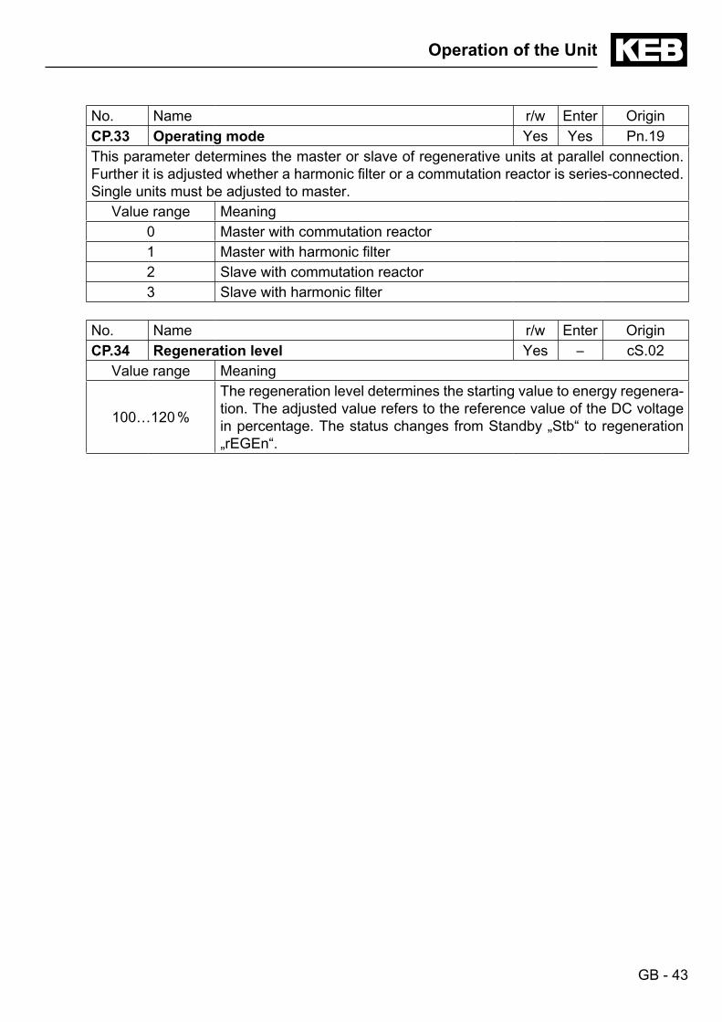
No. Name r/w Enter OriginCP.33 Operating mode Yes Yes Pn.19This parameter determines the master or slave of regenerative units at parallel connection. Further it is adjusted whether a harmonic filter or a commutation reactor is series-connected. Single units must be adjusted to master.
Value range Meaning0 Master with commutation reactor1 Master with harmonic filter2 Slave with commutation reactor3 Slave with harmonic filter
No. Name r/w Enter OriginCP.34 Regeneration level Yes – cS.02
Value range Meaning
100…120 %
The regeneration level determines the starting value to energy regenera-tion. The adjusted value refers to the reference value of the DC voltage in percentage. The status changes from Standby „Stb“ to regeneration „rEGEn“.
GB - 44
Appendix
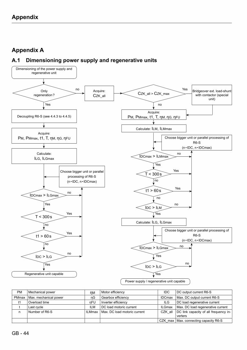
Appendix AA.1 Dimensioning power supply and regenerative units
Dimensioning of the power supply and regenerative unit
Only regeneration ?
DecouplingR6-S(see4.4.3to4.4.5)
Acquire:PM, PMmax,t1,T,ηM, ηG, ηFU
Calculate:ILG, ILGmax
IDCmax>ILGmax
Choose bigger unit or parallel processing of R6-S (n •IDC,n•IDCmax)
t1>60s
Regenerative unit capable
T < 300 s
IDC>ILG
Yes
Yes
no
Yes
no
Yes
no
Yes
no
Acquire:CZK_all CZK_all>CZK_max
Acquire:PM, PMmax,t1,T,ηM, ηG, ηFU
Calculate: ILM, ILMmax
IDCmax>ILMmax
Choose bigger unit or parallel processing of R6-S
(n •IDC,n•IDCmax)
t1>60s
T < 300 s
IDC>ILM
Yes
no
Yes
no
Yes
no
Yes
no
Calculate: ILG, ILGmax
IDCmax>ILGmax
IDC>ILG
Yes
no
Yes
no
Choose bigger unit or parallel processing of R6-S
(n •IDC,n•IDCmax)
Power supply / regenerative unit capable
PM Mechanical power ηM Motorefficiency IDC DC output current R6-SPMmax Max. mechanical power ηG Gearboxefficiency IDCmax Max. DC output current R6-S
t1 Overload time ηFU Inverterefficiency ILG DC load regenerative currentt Lastcycle ILM DC load motoric current ILGmax Max. DC load regenerative currentn Number of R6-S ILMmax Max. DC load motoric current CZK_all DC link capacity of all frequency in-
vertersCZK_max Max. connecting capacity R6-S
Bridgeover ext. load-shunt withcontactor(special
unit)
no Yes
no
GB - 45
Appendix
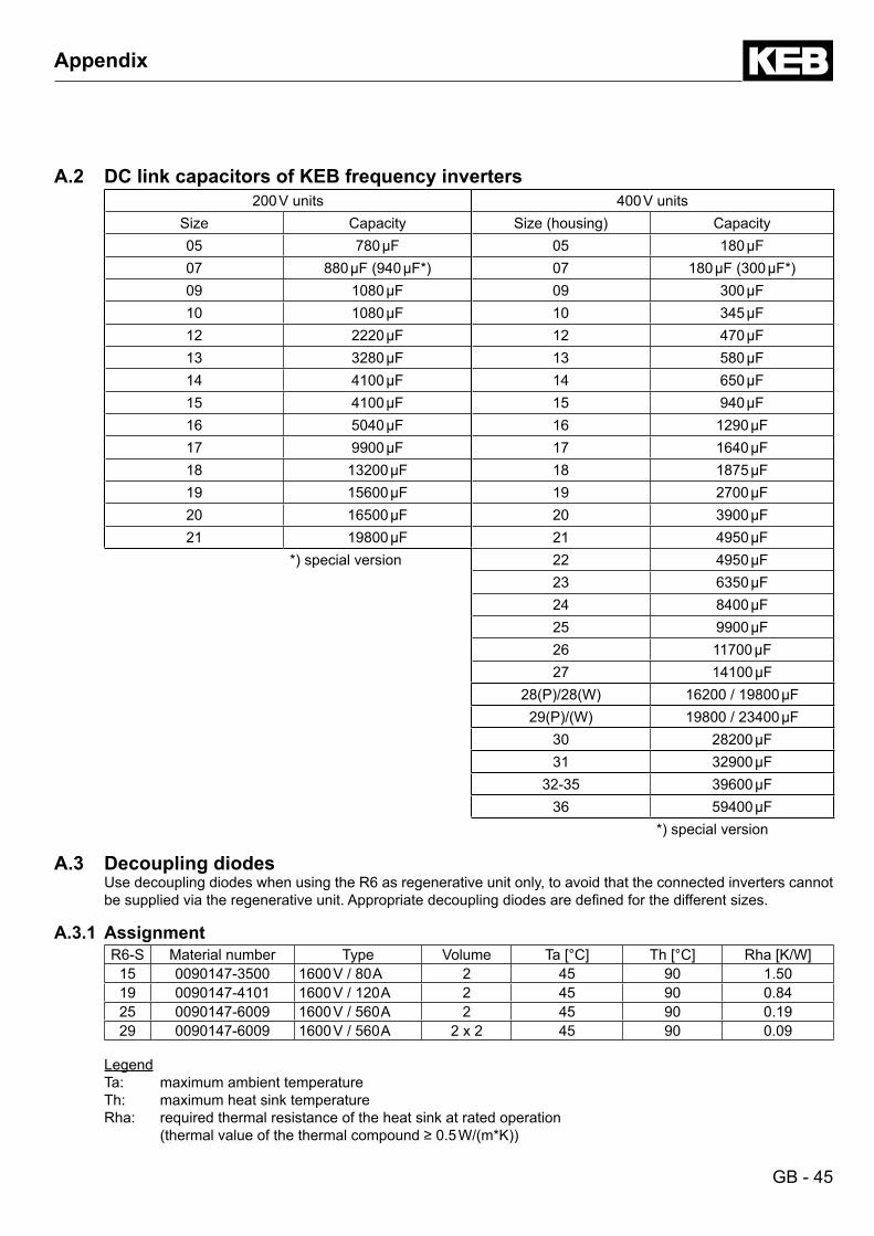
A.2 DC link capacitors of KEB frequency inverters200 V units 400 V units
Size Capacity Size(housing) Capacity05 780 µF 05 180 µF07 880µF(940µF*) 07 180µF(300µF*)09 1080 µF 09 300 µF10 1080 µF 10 345 µF12 2220 µF 12 470 µF13 3280 µF 13 580 µF14 4100 µF 14 650 µF15 4100 µF 15 940 µF16 5040 µF 16 1290 µF17 9900 µF 17 1640 µF18 13200 µF 18 1875 µF19 15600 µF 19 2700 µF20 16500 µF 20 3900 µF21 19800 µF 21 4950 µF
*)specialversion 22 4950 µF23 6350 µF24 8400 µF25 9900 µF26 11700 µF27 14100 µF
28(P)/28(W) 16200 / 19800 µF29(P)/(W) 19800 / 23400 µF
30 28200 µF31 32900 µF
32-35 39600 µF36 59400 µF
*)specialversion
A.3 Decoupling diodesUse decoupling diodes when using the R6 as regenerative unit only, to avoid that the connected inverters cannot besuppliedviatheregenerativeunit.Appropriatedecouplingdiodesaredefinedforthedifferentsizes.
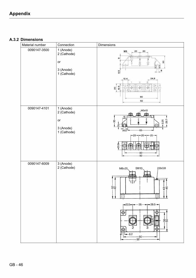
A.3.1 AssignmentR6-S Material number Type Volume Ta [°C] Th [°C] Rha [K/W]
15 0090147-3500 1600 V / 80 A 2 45 90 1.5019 0090147-4101 1600 V / 120 A 2 45 90 0.8425 0090147-6009 1600 V / 560 A 2 45 90 0.1929 0090147-6009 1600 V / 560 A 2 x 2 45 90 0.09
LegendTa: maximum ambient temperatureTh: maximum heat sink temperatureRha: required thermal resistance of the heat sink at rated operation (thermalvalueofthethermalcompound≥0.5W/(m*K))
GB - 46
Appendix
A.3.2 DimensionsMaterial number Connection Dimensions
0090147-3500 1(Anode)2(Cathode)
or
3(Anode)1(Cathode)
0090147-4101 1(Anode)2(Cathode)
or
3(Anode)1(Cathode)
0090147-6009 3(Anode)2(Cathode)
GB - 47
Appendix
Appendix BB.1 Certification
B.1.1 CE MarkingCE marked power supply-/regenerative units were developed and manufactured to comply with the regulations of the Low-Voltage Directive 2006/95/EC.The described units must not be started until it is determined that the installation complies with the Machine directive (2006/42/EG) as well as the EMC-directive (2004/108/EC)(note EN 60204).The power supply-/regenerative units meet the requirements of the Low-Voltage Directive 2006/95/EC. The harmonized standards of the series EN 61800-5-1 in connection with EN 60439-1 and EN 60146 were used.This is a product of limited availability in accordance with IEC 61800-3. This product may cause radio interference in residential areas. In this case the operator may need to take corresponding measures.

KEB Antriebstechnik Austria GmbHRitzstraße8•A-4614 Marchtrenk
fon:+43724353586-0•fax:+43724353586-21net: www.keb.at•mail:[email protected]
KEB AntriebstechnikHerenveld2•B-9500 Geraadsbergen
fon:+3254437860•fax:+3254437898mail: [email protected]
KEB Power Transmission Technology (Shanghai) Co.,Ltd.No. 435 QianPu Road, Songjiang East Industrial Zone,
CHN-201611 Shanghai, P.R. Chinafon:+862137746688•fax:+862137746600
net: www.keb.cn•mail:[email protected]
KEB Antriebstechnik Austria GmbHOrganizačnísložka
K.Weise1675/5•CZ-37004ČeskéBudějovicefon:+420387699111•fax:+420387699119net: www.keb.cz•mail:[email protected]
KEB Antriebstechnik GmbHWildbacherStr.5•D–08289 Schneebergfon:+49377267-0•fax:+49377267-281
mail: [email protected]
KEB EspañaC/Mitjer,Nave8-Pol.Ind.LAMASIA
E-08798SantCugatSesgarrigues(Barcelona)fon:+34938970268•fax:+34938992035
mail: [email protected]
Société Française KEBZ.I.delaCroixSt.Nicolas•14,rueGustaveEiffel
F-94510LAQUEUEENBRIEfon:+33149620101•fax:+33145767495
net: www.keb.fr•mail:[email protected]
KEB (UK) Ltd.6 Chieftain Buisiness Park, Morris Close
Park Farm, Wellingborough GB-Northants, NN8 6 XFfon:+441933402220•fax:+441933400724
net: www.keb-uk.co.uk•mail:[email protected]
KEB Italia S.r.l.ViaNewton,2•I-20019SettimoMilanese(Milano)fon:+390233535311•fax:+390233500790
net: www.keb.it•mail:[email protected]
KEB Japan Ltd.15–16, 2–Chome, Takanawa Minato-ku
J–Tokyo 108-0074fon:+8133445-8515•fax:+8133445-8215
mail: [email protected]
KEB Korea SeoulRoom 1709, 415 Missy 2000
725 Su Seo Dong, Gang Nam GuROK-135-757 Seoul/South Korea
fon:+82262536771•fax:+82262536770mail: [email protected]
KEB RUS Ltd.LesnayaStr.House30,Dzerzhinsky(MO)
RUS-140091 Moscow regionfon:+74955508367•fax:+74956320217
net: www.keb.ru•mail:[email protected]
KEB SverigeBox265(Bergavägen19)
S-43093Hälsöfon:+4631961520•fax:+4631961124
mail: [email protected]
KEB America, Inc.5100 Valley Industrial Blvd. South
USA-Shakopee, MN 55379fon:+1952224-1400•fax:+1952224-1499
net: www.kebamerica.com•mail:[email protected]
© KEBMat.No. 00R6SEB-KP00
Rev. 1HDate 02/2011
More and newest addresses at http://www.keb.de
Karl E. Brinkmann GmbHFörsterweg36-38•D-32683Barntrup
fon:+495263401-0•fax:+495263401-116net: www.keb.de•mail:[email protected]
KEB worldwide…


![a fu titel gb - Electrónica Indústrialelectronicaindustrial.pt/application/uploads/files/00f5bemka02[1].pdf · 2 This manual describes the KEB COMBIVERT F5. Particular attention](https://img.pdfslide.us/doc/110x75/5b4310417f8b9ab15f8baa97/a-fu-titel-gb-electronica-industriale-1pdf-2-this-manual-describes-the.jpg)