Embed Size (px)
Citation preview
STOP
COMBIVERT
Read Instruction Manual Part 1 first !
Mat.No. Rev.00F50EB-KP02 1F
GB INSTRUCTION MANUAL COMBIVERT F5 Power Unit Housing P 200…900 kW
This instruction manual describes the power circuits of the series KEB COMBIVERT F5 housing size P. It is only valid to-gether with the Instruction Manuals Part 1 and Part 3. Both Instruction Manuals must be made available to the user. Before working with the unit the user must become familiar with it. This includes especially the knowledge and observance of the safety and warning directions of part 1. Non-observance of the safety instructions leads to the loss of any liability claims. The pictographs used in this instruction manual have following meaning:
DangerIs used, if life or health of the user is in danger or if substantial damage to property can occur.Warning
Caution
AttentionIs used, if a measure is necessary for the safe and trouble-free operation.observe at
all costs
InformationIs used, if a measure simplifies the handling or operation of the unit.Aid
Tip
The information contained in the technical documentation, as well as any user-specific advice in spoken and written and through tests, are made to best of our knowledge and information about the application. However, they are considered for information only without responsibility. This also applies to any violation of industrial property rights of a third-party. Inspection of our units in view of their suitability for the intended use must be done generally by the user. Inspections are particulary necessary, if changes are executed, which serve for the further development or adaption of our products to the applications (hardware, software or download lists). Inspections must be repeated completely, even if only parts of hardware, software or download lists are modified. Original spare parts and authorized accessories by the manufacturer serve as security. The use of other parts excludes liability for the consequences arising out of.Application and use of our units in the target products is outside of our control and therefore exclusively in the area of responsibility of the user.
GB - 3
Table of Contents
1. General ......................................................41.1 Product description ........................................ 41.2 Specifiedapplication ...................................... 41.3 Part code for standard units .......................... 51.4 Installation instructions .................................. 61.4.1 Cooling systems ................................................ 61.4.2 Safety relay for „safety stop in accordance
with EN954-1/ category 3“ ................................. 61.4.3 Control cabinet installation ................................ 71.4.4 Assembly aid ..................................................... 71.5 Installation of water-cooled units .................. 81.5.1 Heat sink and operating pressure ..................... 81.5.2 Materials in the cooling cicuit ............................ 81.5.3 Requirements on the coolant ............................ 91.5.4 Connection to the cooling system ..................... 91.5.5 Coolant temperature and moisture
condensation ................................................... 101.5.6 Coolant heating depending on power loss
and flow rate with water ...................................111.5.7 Typically fall of pressure depending on the
rate of flow ........................................................11
2. Technical Data .........................................122.1 Operating conditions .................................... 122.2 Technical data of the 400 V class ................. 132.3 Technical data of the 690 V class ................. 142.4 Dimensions and weights .............................. 152.4.1 Dimensions air-cooled inverter mounting
version ............................................................. 152.4.2 Dimensions air-cooled inverter
through-mount version .................................... 162.4.3 Dimensions water-cooled
inverter through-mount version ....................... 172.4.4 Dimensions water-cooled inverter mounted
version ............................................................. 182.5 Connection Accessories .............................. 192.5.1 Filter and chokes ............................................. 192.5.2 Technical data filter ......................................... 192.5.3 Technical data of mains chokes 4% Uk ........... 202.5.4 Technical data of motor chokes ....................... 202.6 Connection Power Unit ................................. 212.6.1 Terminal strips of the power circuit .................. 212.6.2 Mains- and motor connection .......................... 222.6.3 Selection of the motor cable ............................ 242.6.4 Bridges at the symmetry chokes ..................... 242.6.5 Connection of the motor .................................. 242.6.6 Protection against high motor wearing when
inverter operation ............................................ 252.6.7 Temperature detection T1, T2 ......................... 262.6.8 Use of the temperature input in KTY mode ..... 272.6.9 Use of the temperature input in PTC mode ..... 272.6.10 Connection of a braking resistor ..................... 282.6.10.1 Connection of a braking resistor without
temperature monitoring ................................... 28
2.6.10.2 Connection of a braking resistor with over-heat protection and GTR7 monitoring (water-cooled inverter) ........................................................... 28
2.6.10.3 Connection of a braking resistor with over-heat protection without GTR7 monitoring (air-cooled inverter) ........................................................... 30
2.6.11 External fan power supply ............................... 312.6.12 Connection of the master/slave wiring ............ 32
Annex A ..........................................................33A.1 Overload characteristic ................................ 33A.2 Overload protection in the lower speed
range .............................................................. 33A.3 Calculation of the motor voltage ................. 33A.4 Protection with MCCB in accordance
with UL 489 (UL: DIVQ) ................................. 34A.5 Maintenance .................................................. 34A.6 Shut down ...................................................... 34A.6.1 Storage ............................................................ 34A.6.2 Cooling circuit .................................................. 35
Annex B ..........................................................36B.1 Certification ................................................... 36B.1.1 CE Marking ..................................................... 36B.1.2 UL Marking ...................................................... 36
GB - 4
General
1. General1.1 Product description
In selecting the KEB COMBIVERT you have acquired a frequency inverter with the highest demands on quality and dynamic. This instruction manual describes the following units:Unit type: Frequency inverterSeries: COMBIVERT F5Power range: 200…315 kW as single unit
400…900 kW as a combination of two or three single units in master/slave ope-ration
Voltage class: 400 V/ 690 VHousing size: PVersion: Heat sink with cooling fan (mounted version)
Heat sink with cooling fan (through-mount version)Water cooling (mounted version)Water cooling (through-mount version)
Features of the power circuits :• only slight switching losses due to IGBT• extensive safety device for current, voltage and temperature• voltage and current monitoring in static and dynamic operation• conditionally short circuit proof and earth-fault proof• hardware current limit• integrated cooling fan
1.2 SpecifiedapplicationThe KEB COMBIVERT serves exclusively for stepless open loop / closed-loop speed control of three-phase a.c. motors.
The operation of other electric consumers is prohibited and can lead to the destruction of the unit.
The used semiconductors and components of KEB are developed and dimensioned for the use in industrial products. If the KEB COMBIVERT is used in machines, which work under exceptional conditions or if essential functions, life-supporting measures or an extraordinary safety step must be fulfilled, the necessary reliability and security must be ensured by the machine builder. The operation of the KEB COMBIVERT outside the indicated limit values of the technical data leads to the loss of any liability claims.
GB - 5
General
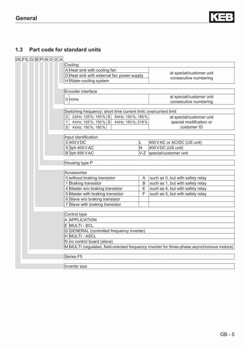
1.3 Part code for standard units
28 .F5 . G B P- 9 0 0 ACoolingA Heat sink with cooling fan at special/customer unit
consecutive numberingD Heat sink with external fan power supplyH Water-cooling system
Encoder interface
0 none at special/customer unitconsecutive numbering
Switching frequency; short time current limit; overcurrent limit0 2 kHz; 125 %; 150 % 6 8 kHz; 150 %; 180 % at special/customer unit
special modification orcustomer ID
1 4 kHz; 125 %; 150 % 9 4 kHz; 180 %; 216 %5 4 kHz; 150 %; 180 %
Input identification5 400 V DC L 400 V AC or AC/DC (US unit)9 3ph 400 V AC N 400 V DC (US unit)B 3ph 690 V AC V-Z special/customer unit
Housing type P
Accessories0 without braking transistor A such as 0, but with safety relay1 Braking transistor B such as 1, but with safety relay4 Master w/o braking transistor E such as 4, but with safety relay5 Master with braking transistor F such as 5, but with safety relay6 Slave w/o braking transistor7 Slave with braking transistor
Control typeA APPLICATIONE MULTI - SCLG GENERAL (controlled frequency inverter)H MULTI - ASCLN no control board (slave)M MULTI (regulated, field-oriented frequency inverter for three-phase asynchronous motors)
Series F5
Inverter size
GB - 6
General
1.4 Installation instructions
1.4.1 Cooling systemsThe KEB COMBIVERT F5 is available for different cooling systems:
Heat sink with cooling fan (mounted version)The standard version is delivered with heat sink and cooling fan.
Special versionsThe dissipation of power loss must be guaranteed by the machine builder.• Water cooling This version is dimensioned for the connection to an available cooling system. The dissipation of the power loss
must be ensured by the machine builder. In order to avoid moisture condensation, the minimum inlet tempe-rature may not decrease the ambient temperature. The max. inlet temperature may not exceed 40°C. No ag-gressive coolant shall be used. Measures against contamination and calcination must be done externally. Max. pressure on the cooling system may not exceed 10 bar (special versions with higher compression strenghts possible on request).
CAUTION!
DO NOT TOUCH!Hot Surfaces
© 2005 KEB
In case of burn, cool inflicted area immediately and seek medical attention.
Heat sinks can reach temperatures, which can cause burns when touching. If in case of structural measures a direct contact cannot be avoided, a warning notice "hot sur-face" must be mounted at the machine.
1.4.2 Safety relay for „safety stop in accordance with EN954-1/ category 3“With the function "safety stop" one of the following conditions must be fulfilled:• the power supply to the drive must be interrupted (double security)• no torque at the drive
The KEB COMBIVERT F5 with safety relay fulfills the condition: no torque by a safe disconnection of the driver signals for the power modules (IGBT). There is no voltage disconnection.This is guaranteed by a two-channel processing holding signal. On of the channels is developed in programmed electronics. The second channel consists of an electro-mechanical relay. The function of the relay is cyclically monitored by the programmed electronics.
Through the double safety no further measure is needed for the KEB COMBIVERT (e.g. feedback via relay contact) since an individual error in the control does not lead to the loss of the stop function.
GB - 7
General
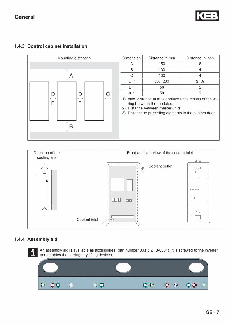
1.4.3 Control cabinet installation
Mounting distances Dimension Distance in mm Distance in inch
C
A
B
DD
EE
A 150 6B 100 4C 100 4
D 1) 50…230 2…9E 2) 50 2X 3) 50 2
1) max. distance at master/slave units results of the wi-ring between the modules.
2) Distance between master units.3) Distance to preceding elements in the cabinet door.
Direction of the cooling fins
Front and side view of the coolant inlet
Coolant outlet
Coolant inlet
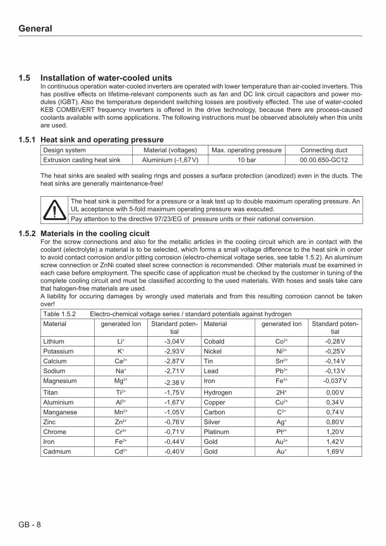
1.4.4 Assembly aid
An assembly aid is available as accessories (part number 00.F5.ZTB-0001). It is screwed to the inverter and enables the carriage by lifting devices.
GB - 8
General
1.5 Installation of water-cooled unitsIn continuous operation water-cooled inverters are operated with lower temperature than air-cooled inverters. This has positive effects on lifetime-relevant components such as fan and DC link circuit capacitors and power mo-dules (IGBT). Also the temperature dependent switching losses are positively effected. The use of water-cooled KEB COMBIVERT frequency inverters is offered in the drive technology, because there are process-caused coolants available with some applications. The following instructions must be observed absolutely when this units are used.
1.5.1 Heat sink and operating pressureDesign system Material (voltages) Max. operating pressure Connecting ductExtrusion casting heat sink Aluminium (-1,67 V) 10 bar 00.00.650-GC12
The heat sinks are sealed with sealing rings and posses a surface protection (anodized) even in the ducts. The heat sinks are generally maintenance-free!
The heat sink is permitted for a pressure or a leak test up to double maximum operating pressure. An UL acceptance with 5-fold maximum operating pressure was executed.Pay attention to the directive 97/23/EG of pressure units or their national conversion.
1.5.2 Materials in the cooling cicuitFor the screw connections and also for the metallic articles in the cooling circuit which are in contact with the coolant (electrolyte) a material is to be selected, which forms a small voltage difference to the heat sink in order to avoid contact corrosion and/or pitting corrosion (electro-chemical voltage series, see table 1.5.2). An aluminum screw connection or ZnNi coated steel screw connection is recommended. Other materials must be examined in each case before employment. The specific case of application must be checked by the customer in tuning of the complete cooling circuit and must be classified according to the used materials. With hoses and seals take care that halogen-free materials are used.A liability for occuring damages by wrongly used materials and from this resulting corrosion cannot be taken over!Table 1.5.2 Electro-chemical voltage series / standard potentials against hydrogenMaterial generated Ion Standard poten-
tialMaterial generated Ion Standard poten-
tialLithium Li+ -3,04 V Cobald Co2+ -0,28 VPotassium K+ -2,93 V Nickel Ni2+ -0,25 VCalcium Ca2+ -2,87 V Tin Sn2+ -0,14 VSodium Na+ -2,71 V Lead Pb3+ -0,13 VMagnesium Mg2+ -2.38 V Iron Fe3+ -0,037 V
Titan Ti2+ -1,75 V Hydrogen 2H+ 0,00 VAluminium Al3+ -1,67 V Copper Cu2+ 0,34 VManganese Mn2+ -1,05 V Carbon C2+ 0,74 VZinc Zn2+ -0,76 V Silver Ag+ 0,80 VChrome Cr3+ -0,71 V Platinum Pt2+ 1,20 VIron Fe2+ -0,44 V Gold Au3+ 1,42 VCadmium Cd2+ -0,40 V Gold Au+ 1,69 V
GB - 9
General
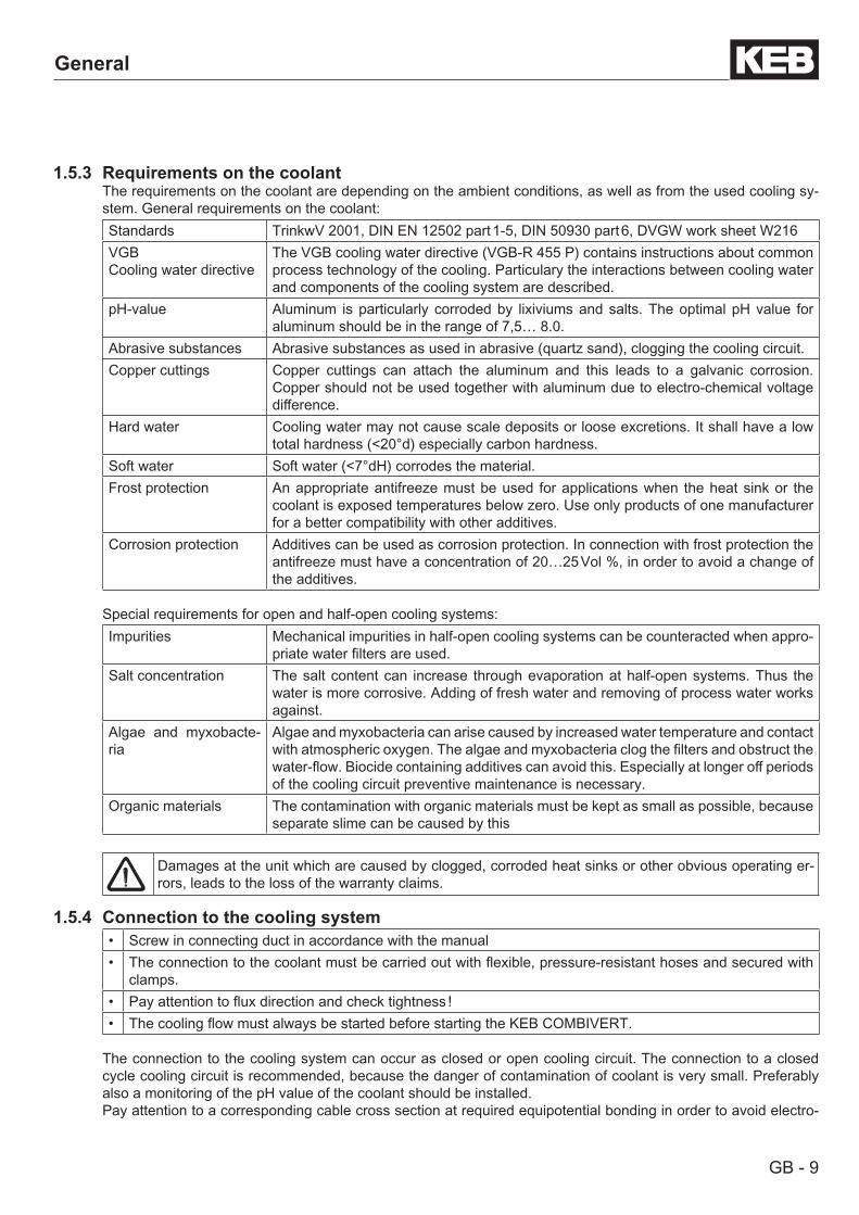
1.5.3 Requirements on the coolantThe requirements on the coolant are depending on the ambient conditions, as well as from the used cooling sy-stem. General requirements on the coolant:Standards TrinkwV 2001, DIN EN 12502 part 1-5, DIN 50930 part 6, DVGW work sheet W216VGBCooling water directive
The VGB cooling water directive (VGB-R 455 P) contains instructions about common process technology of the cooling. Particulary the interactions between cooling water and components of the cooling system are described.
pH-value Aluminum is particularly corroded by lixiviums and salts. The optimal pH value for aluminum should be in the range of 7,5… 8.0.
Abrasive substances Abrasive substances as used in abrasive (quartz sand), clogging the cooling circuit.Copper cuttings Copper cuttings can attach the aluminum and this leads to a galvanic corrosion.
Copper should not be used together with aluminum due to electro-chemical voltage difference.
Hard water Cooling water may not cause scale deposits or loose excretions. It shall have a low total hardness (<20°d) especially carbon hardness.
Soft water Soft water (<7°dH) corrodes the material. Frost protection An appropriate antifreeze must be used for applications when the heat sink or the
coolant is exposed temperatures below zero. Use only products of one manufacturer for a better compatibility with other additives.
Corrosion protection Additives can be used as corrosion protection. In connection with frost protection the antifreeze must have a concentration of 20…25 Vol %, in order to avoid a change of the additives.
Special requirements for open and half-open cooling systems:Impurities Mechanical impurities in half-open cooling systems can be counteracted when appro-
priate water filters are used.Salt concentration The salt content can increase through evaporation at half-open systems. Thus the
water is more corrosive. Adding of fresh water and removing of process water works against.
Algae and myxobacte-ria
Algae and myxobacteria can arise caused by increased water temperature and contact with atmospheric oxygen. The algae and myxobacteria clog the filters and obstruct the water-flow. Biocide containing additives can avoid this. Especially at longer off periods of the cooling circuit preventive maintenance is necessary.
Organic materials The contamination with organic materials must be kept as small as possible, because separate slime can be caused by this
Damages at the unit which are caused by clogged, corroded heat sinks or other obvious operating er-rors, leads to the loss of the warranty claims.
1.5.4 Connection to the cooling system• Screw in connecting duct in accordance with the manual• The connection to the coolant must be carried out with flexible, pressure-resistant hoses and secured with
clamps.• Pay attention to flux direction and check tightness !• The cooling flow must always be started before starting the KEB COMBIVERT.
The connection to the cooling system can occur as closed or open cooling circuit. The connection to a closed cycle cooling circuit is recommended, because the danger of contamination of coolant is very small. Preferably also a monitoring of the pH value of the coolant should be installed.Pay attention to a corresponding cable cross section at required equipotential bonding in order to avoid electro-
GB - 10
General
chemical procedures.
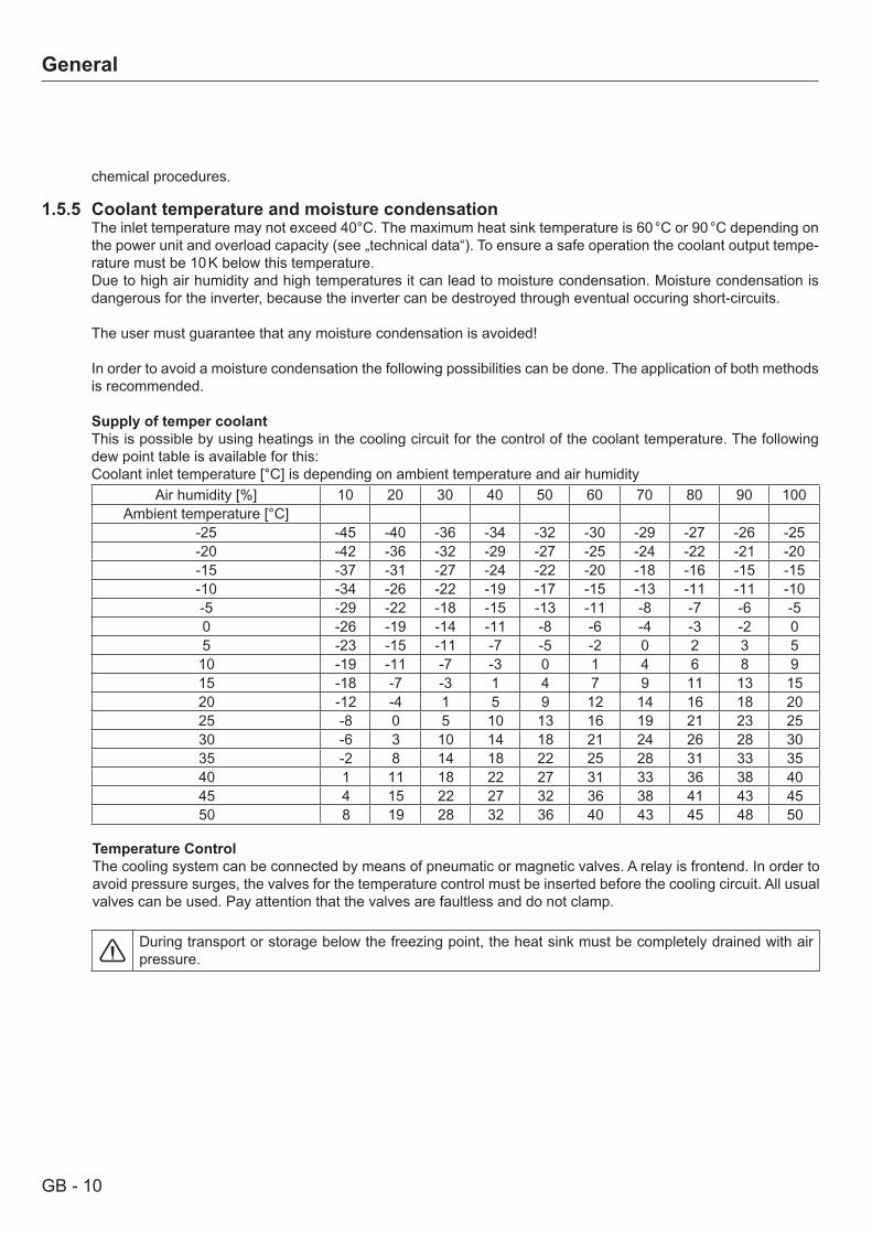
1.5.5 Coolant temperature and moisture condensationThe inlet temperature may not exceed 40°C. The maximum heat sink temperature is 60 °C or 90 °C depending on the power unit and overload capacity (see „technical data“). To ensure a safe operation the coolant output tempe-rature must be 10 K below this temperature. Due to high air humidity and high temperatures it can lead to moisture condensation. Moisture condensation is dangerous for the inverter, because the inverter can be destroyed through eventual occuring short-circuits.
The user must guarantee that any moisture condensation is avoided!
In order to avoid a moisture condensation the following possibilities can be done. The application of both methods is recommended. Supply of temper coolantThis is possible by using heatings in the cooling circuit for the control of the coolant temperature. The following dew point table is available for this:Coolant inlet temperature [°C] is depending on ambient temperature and air humidity
Air humidity [%] 10 20 30 40 50 60 70 80 90 100Ambient temperature [°C]
-25 -45 -40 -36 -34 -32 -30 -29 -27 -26 -25-20 -42 -36 -32 -29 -27 -25 -24 -22 -21 -20-15 -37 -31 -27 -24 -22 -20 -18 -16 -15 -15-10 -34 -26 -22 -19 -17 -15 -13 -11 -11 -10-5 -29 -22 -18 -15 -13 -11 -8 -7 -6 -50 -26 -19 -14 -11 -8 -6 -4 -3 -2 05 -23 -15 -11 -7 -5 -2 0 2 3 510 -19 -11 -7 -3 0 1 4 6 8 915 -18 -7 -3 1 4 7 9 11 13 1520 -12 -4 1 5 9 12 14 16 18 2025 -8 0 5 10 13 16 19 21 23 2530 -6 3 10 14 18 21 24 26 28 3035 -2 8 14 18 22 25 28 31 33 3540 1 11 18 22 27 31 33 36 38 4045 4 15 22 27 32 36 38 41 43 4550 8 19 28 32 36 40 43 45 48 50
Temperature ControlThe cooling system can be connected by means of pneumatic or magnetic valves. A relay is frontend. In order to avoid pressure surges, the valves for the temperature control must be inserted before the cooling circuit. All usual valves can be used. Pay attention that the valves are faultless and do not clamp.
During transport or storage below the freezing point, the heat sink must be completely drained with air pressure.
GB - 11
General
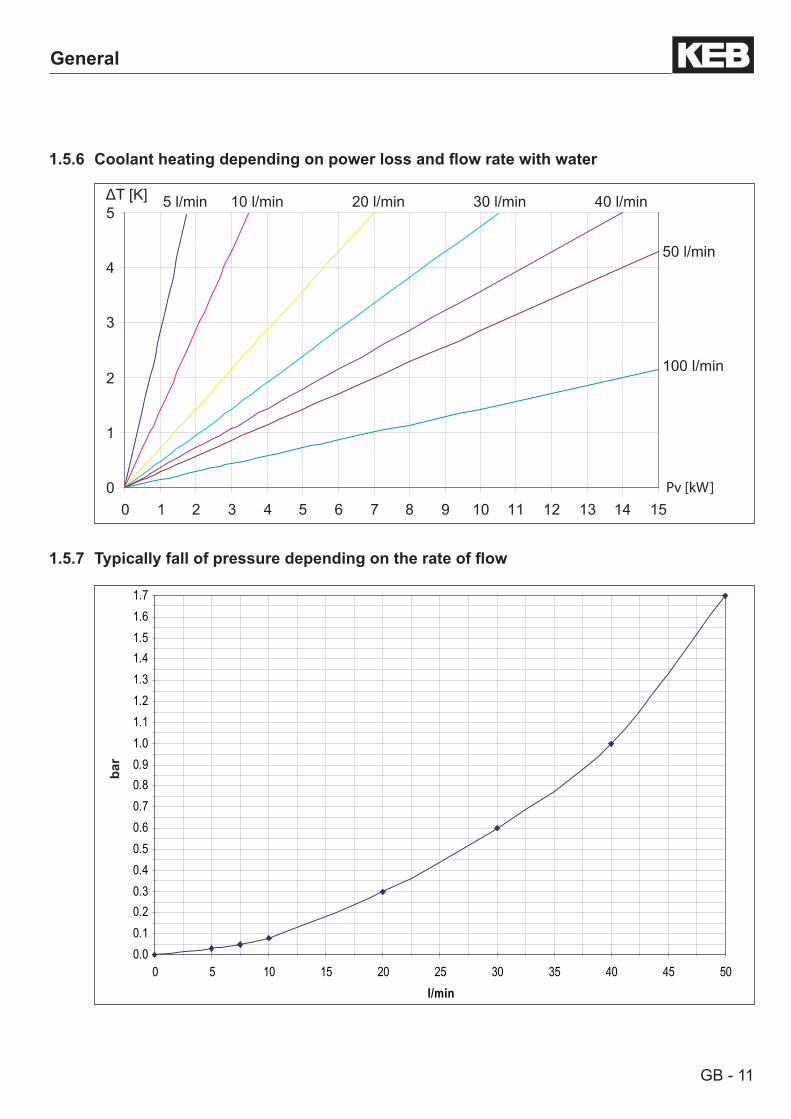
1.5.6 Coolantheatingdependingonpowerlossandflowratewithwater
0
1
2
3
4
5
0 1 2 3 4 5 6 7 8 9 10 11 12 13 14 15Pv [kW]
ΔT [K]
100 l/min
50 l/min
40 l/min30 l/min20 l/min10 l/min5 l/min
1.5.7 Typicallyfallofpressuredependingontherateofflow
bar
0.00.10.20.30.40.50.60.70.80.91.01.11.21.31.41.51.61.7
0 5 10 15 20 25 30 35 40 45 50l/min
GB - 12
Technical Data
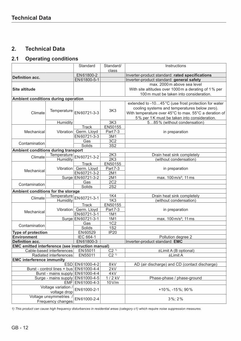
2. Technical Data2.1 Operating conditions
Standard Standard/class
Instructions
Definitionacc. EN 61800-2 Inverter-product standard: ratedspecificationsEN 61800-5-1 Inverter-product standard: general safety
Site altitudemax. 2000 m above sea level
With site altitudes over 1000 m a derating of 1 % per 100 m must be taken into consideration.
Ambient conditions during operation
Climate Temperature EN 60721-3-3 3K3
extended to -10…45 °C (use frost protection for water cooling systems and temperatures below zero).
With temperature over 45°C to max. 55°C a deration of 5 % per 1 K must be taken into consideration.
Humidity 3K3 5…85 % (without condensation)
Mechanical VibrationTrack EN50155
in preparationGerm. Lloyd Part 7-3EN 60721-3-3 3M1
Contamination Gas 3C2Solids 3S2
Ambient conditions during transportClimate Temperature EN 60721-3-2 2K3 Drain heat sink completely
Humidity 2K3 (without condensation)
Mechanical VibrationTrack EN50155
in preparationGerm. Lloyd Part 7-3EN 60721-3-2 2M1
Surge EN 60721-3-2 2M1 max. 100 m/s²; 11 ms
Contamination Gas 2C2Solids 2S2
Ambient conditions for the storageClimate Temperature EN 60721-3-1 1K4 Drain heat sink completely
Humidity 1K3 (without condensation)
Mechanical VibrationTrack EN50155
in preparationGerm. Lloyd Part 7-3EN 60721-3-1 1M1
Surge EN 60721-3-1 1M1 max. 100 m/s²; 11 ms
Contamination Gas 1C2Solids 1S2
Type of protection EN 60529 IP20Environment IEC 664-1 Pollution degree 2Definitionacc. EN 61800-3 Inverter-product standard: EMCEMC emitted interference (see instruction manual)
Cable-based interferences EN 55011 C2 1) ≙Limit A (B optional)Radiated interferences EN55011 C2 1) ≙Limit A
EMC interference immunityESD EN 61000-4-2 8 kV AD (air discharge) and CD (contact discharge)
Burst - control lines + bus EN 61000-4-4 2 kVBurst - mains supply EN 61000-4-4 4 kV
Surge - mains supply EN 61000-4-5 1 / 2 kV Phase-phase / phase-groundEMF EN 61000-4-3 10 V/m
Voltage variation /voltage drop EN 61000-2-1 +10 %, -15 %; 90 %
Voltage unsymmetries / Frequency changes EN 61000-2-4 3 %; 2 %
1) This product can cause high frequency disturbances in residential areas (category c1) which require noise suppression measures.
GB - 13
Technical Data
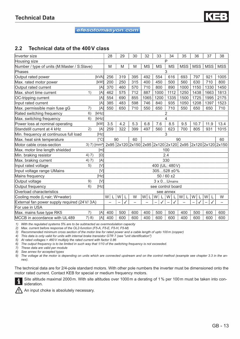
Inverter size 28 29 30 32 33 34 35 36 37 38Housing size PNumber / type of units (M:Master / S:Slave) M M M MS MS MS MSS MSS MSS MSSPhases 3Output rated power [kVA] 256 319 395 492 554 616 693 797 921 1005Max. rated motor power [kW] 200 250 315 400 450 500 560 630 710 800Output rated current [A] 370 460 570 710 800 890 1000 1150 1330 1450Max. short time current 1) [A] 462 575 712 887 1000 1112 1250 1438 1663 1813OC-tripping current [A] 554 690 855 1065 1200 1335 1500 1725 1995 2175Input rated current [A] 385 483 598 746 840 935 1050 1208 1397 1523Max. permissible main fuse gG 7) [A] 550 650 710 550 650 710 550 650 650 710Rated switching frequency 6) [kHz] 2Max. switching frequency 6) [kHz] 4Power loss at nominal operating [kW] 3.5 4.2 5.3 6.8 7.6 8.5 9.5 10.7 11.9 13.4Standstill current at 4 kHz 2) [A] 259 322 399 497 560 623 700 805 931 1015Min. frequency at continuous full load [Hz] 3Max. heat sink temperature [°C] 90 60 90 60Motor cable cross-section 3) 7) [mm²] 2x95 2x120 2x150 2x95 2x120 2x120 2x95 2x120 2x120 2x150Max. motor line length shielded [m] 100Min. braking resistor 4) 7) [Ω] 2.4Max. braking current 4) 7) [A] 330Input rated voltage 5) [V] 400 (UL: 480 V)Input voltage range UMains [V] 305…528 ±0 %Mains frequency [Hz] 50 / 60 ±2Output voltage 9) [V] 3 x 0…UmainsOutput frequency 6) [Hz] see control boardOverload characteristics see annexCooling mode (L=air; W=water) W L W L W W L W L W L W L W L W L WExternal fan power supply required (24 V/ 3 A) – – – – – – – – – –For use in USAMax. mains fuse type RK5 7) [A] 400 500 600 400 500 500 400 500 600 600MCCB in accordance with UL 489 7) 8) [A] 400 600 600 400 600 600 400 600 600 6001) With the regulated systems 5% are to be subtracted as overmodulation capacity2) Max. current before response of the OL2-function (F5-A, F5-E, F5-H, F5-M)3) Recommended minimum cross section of the motor line for rated power and a cable length of upto 100 m (copper)4) This data is only valid for units with internal brake transistor GTR 7 (see "unit identification")5) At rated voltages > 460 V multiply the rated current with factor 0.866) The output frequency is to be limited in such way that 1/10 of the switching frequency is not exceeded.7) These data are valid per module8) See annex for accepted types9) The voltage at the motor is depending on units which are connected upstream and on the control method (example see chapter 3.3 in the an-
nex).
The technical data are for 2/4-pole standard motors. With other pole numbers the inverter must be dimensioned onto the motor rated current. Contact KEB for special or medium frequency motors.
Site altitude maximal 2000 m. With site altitudes over 1000 m a derating of 1 % per 100 m must be taken into con-sideration.An input choke is absolutely necessary.
2.2 Technical data of the 400 V class
GB - 14
Technical Data
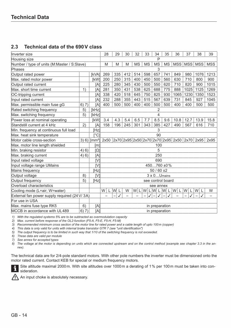
2.3 Technical data of the 690 V classInverter size 28 29 30 32 33 34 35 36 37 38 39Housing size PNumber / type of units (M:Master / S:Slave) M M M MS MS MS MS MSS MSS MSS MSSPhases 3Output rated power [kVA] 269 335 412 514 598 657 741 849 980 1076 1213Max. rated motor power [kW] 200 250 315 400 450 500 560 630 710 800 900Output rated current [A] 225 280 345 430 500 550 620 710 820 900 1015Max. short time current 1) [A] 281 350 431 538 625 688 775 888 1025 1125 1269OC-tripping current [A] 338 420 518 645 750 825 930 1065 1230 1350 1523Input rated current [A] 232 288 355 443 515 567 639 731 845 927 1045Max. permissible main fuse gG 6) 7) [A] 400 500 500 400 400 500 500 400 400 500 500Rated switching frequency 5) [kHz] 2Max. switching frequency 5) [kHz] 4Power loss at nominal operating [kW] 3.4 4.3 5.4 6.5 7.7 8.5 9.6 10.8 12.7 13.9 15.8Standstill current at 4 kHz 2) [A] 158 196 245 301 343 385 427 490 567 616 710Min. frequency at continuous full load [Hz] 3Max. heat sink temperature [°C] 90Motor cable cross-section 3) 6) [mm²] 2x50 2x70 2x95 2x50 2x70 2x70 2x95 2x50 2x70 2x95 2x95Max. motor line length shielded [m] 100Min. braking resistor 4) 6) [Ω] 5Max. braking current 4) 6) [A] 250Input rated voltage [V] 690Input voltage range UMains [V] 450…760 ±0 %Mains frequency [Hz] 50 / 60 ±2Output voltage 8) [V] 3 x 0…UmainsOutput frequency 5) [Hz] see control boardOverload characteristics see annexCooling mode (L=air; W=water) W L W L W W L W L W L W L W L W L W L WExternal fan power supply required (24 V/ 3 A) – – – – – – – – – – –For use in USAMax. mains fuse type RK5 6) [A] in preparationMCCB in accordance with UL 489 6) 7) [A] in preparation1) With the regulated systems 5% are to be subtracted as overmodulation capacity2) Max. current before response of the OL2-function (F5-A, F5-E, F5-H, F5-M)3) Recommended minimum cross section of the motor line for rated power and a cable length of upto 100 m (copper)4) This data is only valid for units with internal brake transistor GTR 7 (see "unit identification")5) The output frequency is to be limited in such way that 1/10 of the switching frequency is not exceeded.6) These data are valid per module7) See annex for accepted types8) The voltage at the motor is depending on units which are connected upstream and on the control method (example see chapter 3.3 in the an-
nex).
The technical data are for 2/4-pole standard motors. With other pole numbers the inverter must be dimensioned onto the motor rated current. Contact KEB for special or medium frequency motors.
Site altitude maximal 2000 m. With site altitudes over 1000 m a derating of 1 % per 100 m must be taken into con-sideration.An input choke is absolutely necessary.
GB - 15
Technical Data - Dimensions and Weights
2.4 Dimensions and weights
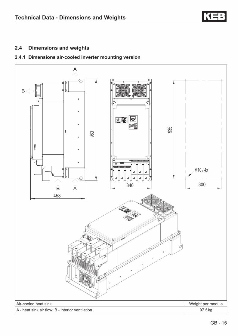
2.4.1 Dimensions air-cooled inverter mounting version
Air-cooled heat sink Weight per moduleA - heat sink air flow; B - interior ventilation 97.5 kg
453
960 93
5
300340
M10 / 4x
B
B
A
A
GB - 16
Technical Data - Dimensions and Weights
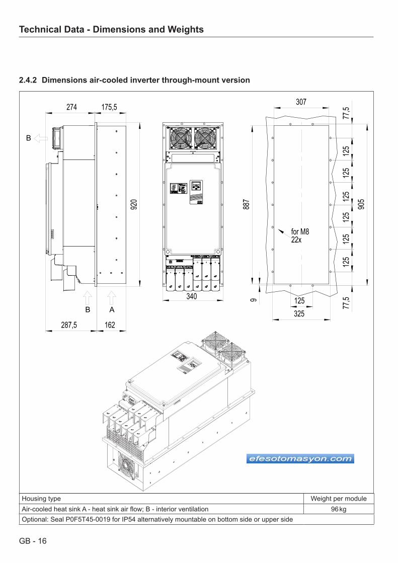
Housing type Weight per moduleAir-cooled heat sink A - heat sink air flow; B - interior ventilation 96 kgOptional: Seal P0F5T45-0019 for IP54 alternatively mountable on bottom side or upper side
2.4.2 Dimensions air-cooled inverter through-mount version
340
274
287,5
920
175,5
162
125
125
125
125
125
125
77,5
307
325125
905
77,5
988
7for M822x
AB
B
GB - 17
Technical Data - Dimensions and Weights
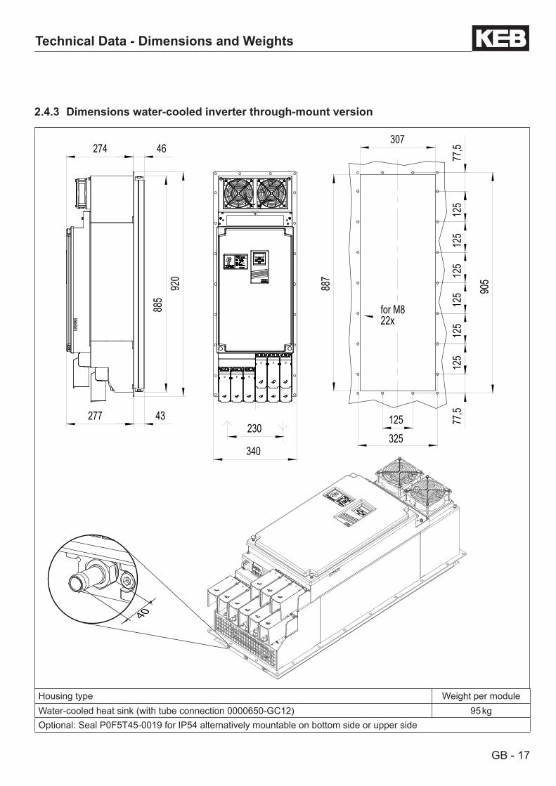
Housing type Weight per moduleWater-cooled heat sink (with tube connection 0000650-GC12) 95 kgOptional: Seal P0F5T45-0019 for IP54 alternatively mountable on bottom side or upper side
2.4.3 Dimensions water-cooled inverter through-mount version
230
340
274
277
885
46
43
920
887
307
77,5
125
125
125
125
125
125
77,5
125325
905
for M822x
40
GB - 18
Technical Data - Dimensions and Weights
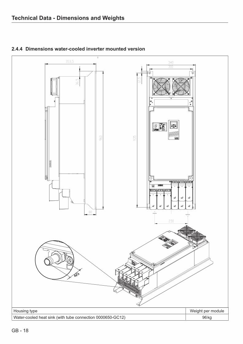
Housing type Weight per moduleWater-cooled heat sink (with tube connection 0000650-GC12) 96 kg
2.4.4 Dimensions water-cooled inverter mounted version
300340
935
12,5
353,5
80
960
36,5
230
40
GB - 19
Connection Power Unit
2.5 Connection Accessories
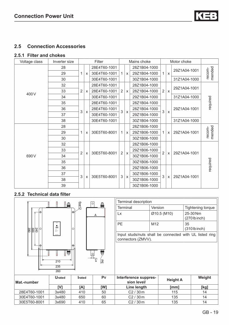
2.5.1 Filter and chokesVoltage class Inverter size Filter Mains choke Motor choke
400 V
281 x
28E4T60-10011 x
28Z1B04-10001 x
29Z1A04-1001
reco
m-
men
ded
29 30E4T60-1001 29Z1B04-100030 30E4T60-1001 30Z1B04-1000 31Z1A04-100032
2 x28E4T60-1001
2 x28Z1B04-1000
2 x29Z1A04-1001
requ
ired
33 28E4T60-1001 28Z1B04-100034 30E4T60-1001 29Z1B04-1000 31Z1A04-100035
3 x
28E4T60-1001
3 x
28Z1B04-1000
3 x29Z1A04-100136 28E4T60-1001 28Z1B04-1000
37 30E4T60-1001 29Z1B04-100038 30E4T60-1001 30Z1B04-1000 31Z1A04-1000
690 V
281 x 30E5T60-8001 1 x
28Z1B06-10001 x 29Z1A04-1001
reco
m-
men
ded
29 29Z1B06-100030 30Z1B06-100032
2 x 30E5T60-8001 2 x
28Z1B06-1000
2 x 29Z1A04-1001
requ
ired
33 29Z1B06-100034 30Z1B06-100035 30Z1B06-100036
3 x 30E5T60-8001 3 x
29Z1B06-1000
3 x 29Z1A04-100137 30Z1B06-100038 30Z1B06-100039 30Z1B06-1000
2.5.2 Technicaldatafilter
260 235
210
300 390
240
A
INVERTER
3x480V +5% AC/50-60Hz
HF-FILTER 30.E4.T60-1001
Karl E. Brinkmann GmbH D-32677 Barntrup
650A @ T=45 C HPF:-25 C - +85 C
LINE
6xø12
PE
Lx
Terminal descriptionTerminal Version Tightening torqueLx Ø10.5 (M10) 25-30 Nm
(270 lb inch)PE M12 35
(310 lb inch)Input studs/nuts shall be connected with UL listed ring connectors (ZMVV).
Mat.-numberUrated Irated PV Interference suppres-
sion level/ Height A Weight
[V] [A] [W] Line length [mm] [kg]28E4T60-1001 3x480 410 50 C2 / 30 m 115 1430E4T60-1001 3x480 650 60 C2 / 30 m 135 1430E5T60-8001 3x690 410 65 C2 / 30 m 135 14
GB - 20
Connection Power Unit
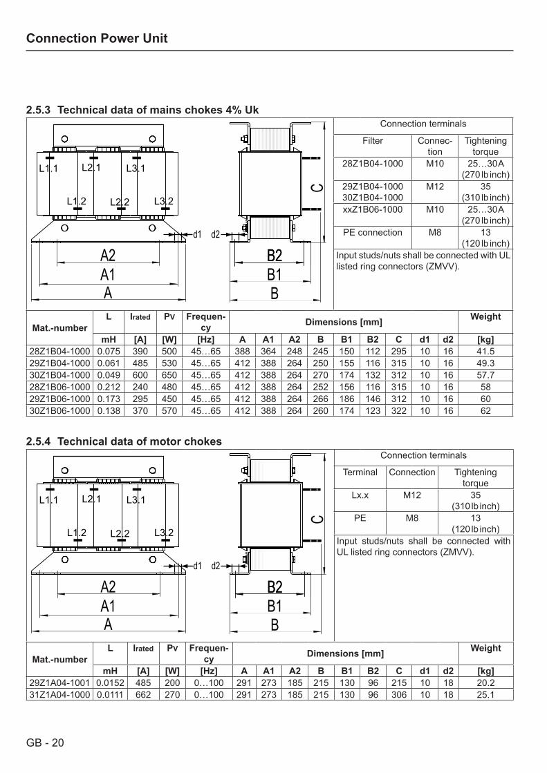
2.5.3 Technical data of mains chokes 4% Uk
d1
C
B1B
B2B2
L1.1
L1.2 L3.2
L2.1
L2.2
L3.1
d2
A2A1A
Connection terminals
Filter Connec-tion
Tightening torque
28Z1B04-1000 M10 25…30 A(270 lb inch)
29Z1B04-100030Z1B04-1000
M12 35(310 lb inch)
xxZ1B06-1000 M10 25…30 A(270 lb inch)
PE connection M8 13(120 lb inch)
Input studs/nuts shall be connected with UL listed ring connectors (ZMVV).
Mat.-numberL Irated PV Frequen-
cy Dimensions [mm] Weight
mH [A] [W] [Hz] A A1 A2 B B1 B2 C d1 d2 [kg]28Z1B04-1000 0.075 390 500 45…65 388 364 248 245 150 112 295 10 16 41.529Z1B04-1000 0.061 485 530 45…65 412 388 264 250 155 116 315 10 16 49.330Z1B04-1000 0.049 600 650 45…65 412 388 264 270 174 132 312 10 16 57.728Z1B06-1000 0.212 240 480 45…65 412 388 264 252 156 116 315 10 16 5829Z1B06-1000 0.173 295 450 45…65 412 388 264 266 186 146 312 10 16 6030Z1B06-1000 0.138 370 570 45…65 412 388 264 260 174 123 322 10 16 62
2.5.4 Technical data of motor chokes
d1
C
B1B
B2B2
L1.1
L1.2 L3.2
L2.1
L2.2
L3.1
d2
A2A1A
Connection terminals
Terminal Connection Tightening torque
Lx.x M12 35(310 lb inch)
PE M8 13(120 lb inch)
Input studs/nuts shall be connected with UL listed ring connectors (ZMVV).
Mat.-numberL Irated PV Frequen-
cy Dimensions [mm] Weight
mH [A] [W] [Hz] A A1 A2 B B1 B2 C d1 d2 [kg]29Z1A04-1001 0.0152 485 200 0…100 291 273 185 215 130 96 215 10 18 20.231Z1A04-1000 0.0111 662 270 0…100 291 273 185 215 130 96 306 10 18 25.1
GB - 21
Connection Power Unit
2.6 Connection Power Unit
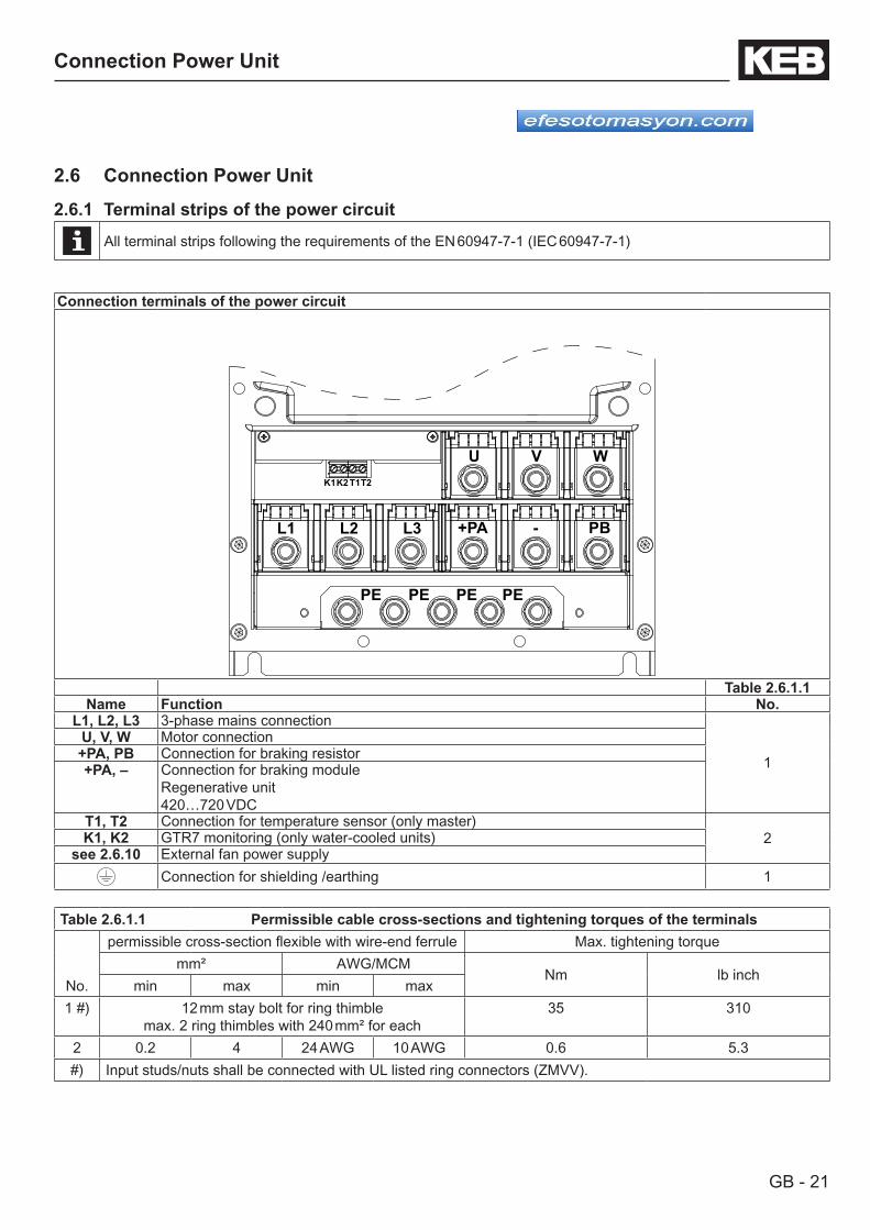
2.6.1 Terminal strips of the power circuit
All terminal strips following the requirements of the EN 60947-7-1 (IEC 60947-7-1)
Connection terminals of the power circuit
U V W
+PA - PBL1 L2 L3
PE PE PE PE
T1T2K1K2
Table 2.6.1.1Name Function No.
L1, L2, L3 3-phase mains connection
1U, V, W Motor connection+PA, PB Connection for braking resistor+PA, – Connection for braking module
Regenerative unit420…720 VDC
T1, T2 Connection for temperature sensor (only master)2K1, K2 GTR7 monitoring (only water-cooled units)
see 2.6.10 External fan power supplyConnection for shielding /earthing 1
Table 2.6.1.1 Permissible cable cross-sections and tightening torques of the terminals
No.
permissible cross-section flexible with wire-end ferrule Max. tightening torquemm² AWG/MCM
Nm lb inchmin max min max
1 #) 12 mm stay bolt for ring thimblemax. 2 ring thimbles with 240 mm² for each
35 310
2 0.2 4 24 AWG 10 AWG 0.6 5.3#) Input studs/nuts shall be connected with UL listed ring connectors (ZMVV).
GB - 22
Connection Power Unit
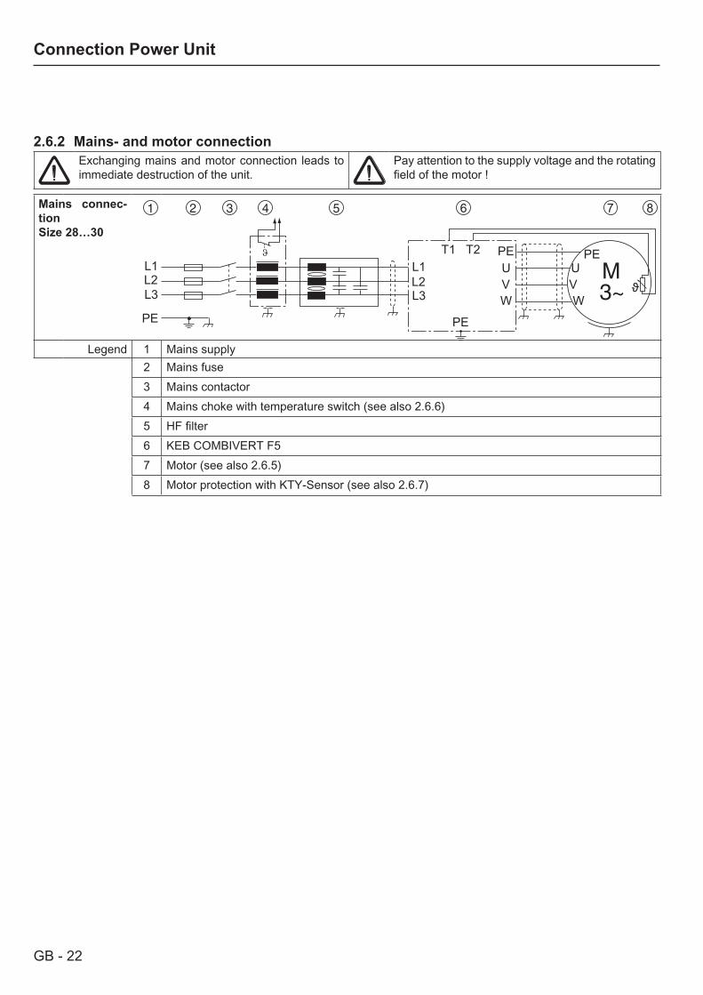
2.6.2 Mains- and motor connectionExchanging mains and motor connection leads to immediate destruction of the unit.
Pay attention to the supply voltage and the rotating field of the motor !
Mains connec-tionSize 28…30
L1L2L3
PE
L1
7 8
L2L3
UVW
PEUVW
PE
PE
T1 T2
Legend 1 Mains supply2 Mains fuse3 Mains contactor4 Mains choke with temperature switch (see also 2.6.6)5 HF filter6 KEB COMBIVERT F57 Motor (see also 2.6.5)8 Motor protection with KTY-Sensor (see also 2.6.7)
GB - 23
Connection Power Unit
Mains connec-tionSize 32…34 L1
L2L3 U
VW
PE
PE
11 1210
7
PE
PEPE
M3~
UPE
VW
3
3T1T2
Mains connec-tionSize 35…38
L1L2L3
UVW
PE
PE
11 1210
7
7
PE
PEPE
PE
M3~
WPE
VU
3
3
3T1T2
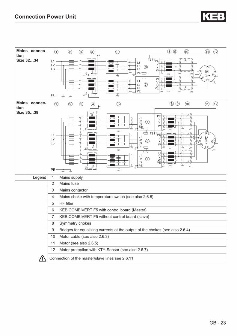
Legend 1 Mains supply2 Mains fuse3 Mains contactor4 Mains choke with temperature switch (see also 2.6.6)5 HF filter6 KEB COMBIVERT F5 with control board (Master)7 KEB COMBIVERT F5 without control board (slave)8 Symmetry chokes9 Bridges for equalizing currents at the output of the chokes (see also 2.6.4)10 Motor cable (see also 2.6.3)11 Motor (see also 2.6.5)12 Motor protection with KTY-Sensor (see also 2.6.7)
Connection of the master/slave lines see 2.6.11
GB - 24
Connection Power Unit
2.6.3 Selection of the motor cableCorrect selection and wiring of the motor cable is very important for high motor ratings:• smaller load of the motor bearings by bearing currents• improved EMC characteristics• lower symmetrical operating capacities• less losses by transient currents
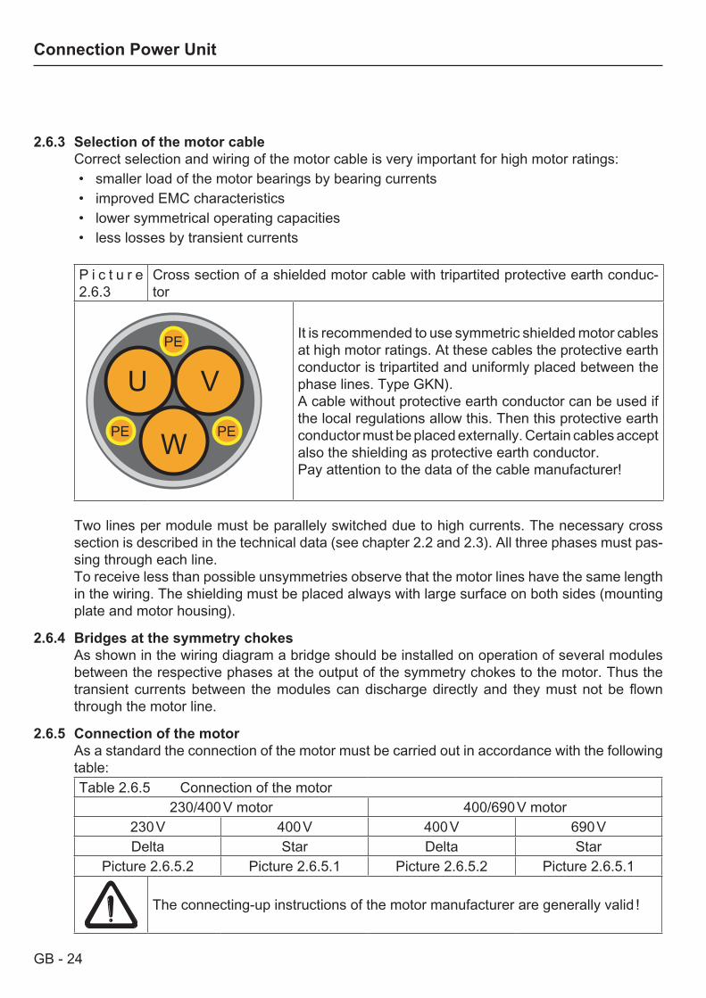
P i c t u r e 2.6.3
Cross section of a shielded motor cable with tripartited protective earth conduc-tor
PE
PE
PE
VU
W
It is recommended to use symmetric shielded motor cables at high motor ratings. At these cables the protective earth conductor is tripartited and uniformly placed between the phase lines. Type GKN).A cable without protective earth conductor can be used if the local regulations allow this. Then this protective earth conductor must be placed externally. Certain cables accept also the shielding as protective earth conductor. Pay attention to the data of the cable manufacturer!
Two lines per module must be parallely switched due to high currents. The necessary cross section is described in the technical data (see chapter 2.2 and 2.3). All three phases must pas-sing through each line.To receive less than possible unsymmetries observe that the motor lines have the same length in the wiring. The shielding must be placed always with large surface on both sides (mounting plate and motor housing).
2.6.4 Bridges at the symmetry chokesAs shown in the wiring diagram a bridge should be installed on operation of several modules between the respective phases at the output of the symmetry chokes to the motor. Thus the transient currents between the modules can discharge directly and they must not be flown through the motor line.
2.6.5 Connection of the motorAs a standard the connection of the motor must be carried out in accordance with the following table:Table 2.6.5 Connection of the motor
230/400 V motor 400/690 V motor230 V 400 V 400 V 690 VDelta Star Delta Star
Picture 2.6.5.2 Picture 2.6.5.1 Picture 2.6.5.2 Picture 2.6.5.1
The connecting-up instructions of the motor manufacturer are generally valid !
GB - 25
Connection Power Unit
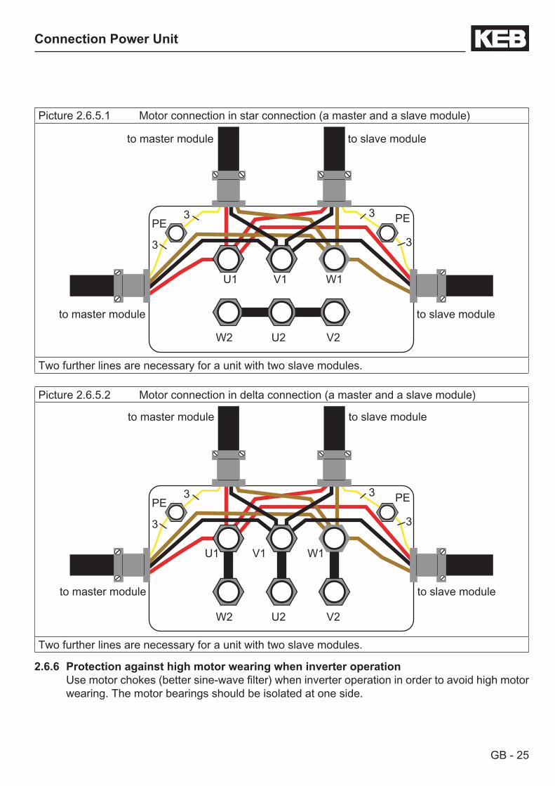
Picture 2.6.5.1 Motor connection in star connection (a master and a slave module)
U1 V1 W1
W2 U2 V2
PE PE
3
3
3
3
Two further lines are necessary for a unit with two slave modules.
Picture 2.6.5.2 Motor connection in delta connection (a master and a slave module)
U1 V1 W1
W2 U2 V2
PE PE
3
3
3
3
Two further lines are necessary for a unit with two slave modules.
2.6.6 Protection against high motor wearing when inverter operationUse motor chokes (better sine-wave filter) when inverter operation in order to avoid high motor wearing. The motor bearings should be isolated at one side.
to master module
to master module to slave module
to slave module
to master module
to master module to slave module
to slave module
GB - 26
Connection Power Unit
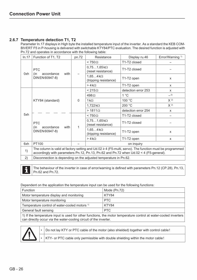
2.6.7 Temperature detection T1, T2Parameter In.17 displays in High byte the installed temperature input of the inverter. As a standard the KEB COM-BIVERT F5 in P-housing is delivered with switchable KTY84/PTC evaluation. The desired function is adjusted with Pn.72 and operates in accordance with the following table:
In.17 Function of T1, T2 pn.72 Resistance Display ru.46 Error/Warning 1)
0xhPTC(in accordance with DIN EN 60947-8)
–
< 750 Ω T1-T2 closed –0,75…1,65 kΩ (reset resistance) T1-T2 closed –
1,65…4 kΩ (tripping resistance) T1-T2 open x
> 4 kΩ T1-T2 open x
5xh
KTY84 (standard) 0
< 215 Ω detection error 253 x498 Ω 1 °C – 2)
1 kΩ 100 °C X 2)
1,722 kΩ 200 °C X 2)
> 1811 Ω detection error 254 x
PTC(in accordance with DIN EN 60947-8)
1
< 750 Ω T1-T2 closed –0,75…1,65 kΩ (reset resistance) T1-T2 closed –
1,65…4 kΩ (tripping resistance) T1-T2 open x
> 4 kΩ T1-T2 open x6xh PT100 – on inquiry
1) The column is valid at factory setting and Ud.02 ≥ 4 (F5-multi, servo). The function must be programmed accordingly with parameters Pn.12, Pn.13, Pn.62 and Pn.72 when Ud.02 < 4 (F5-general).
2) Disconnection is depending on the adjusted temperature in Pn.62.
The behaviour of the inverter in case of error/warning is defined with parameters Pn.12 (CP.28), Pn.13, Pn.62 and Pn.72.
Dependent on the application the temperature input can be used for the following functions:Function Mode (Pn.72)Motor temperature display and monitoring KTY84Motor temperature monitoring PTCTemperature control of water-cooled motors 1) KTY84General fault sensing PTC1) If the temperature input is used for other functions, the motor temperature control at water-cooled inverters can directly occur via the water-cooling circuit of the inverter.
• Do not lay KTY or PTC cable of the motor (also shielded) together with control cable !
• KTY- or PTC cable only permissible with double shielding within the motor cable !
GB - 27
Connection Power Unit
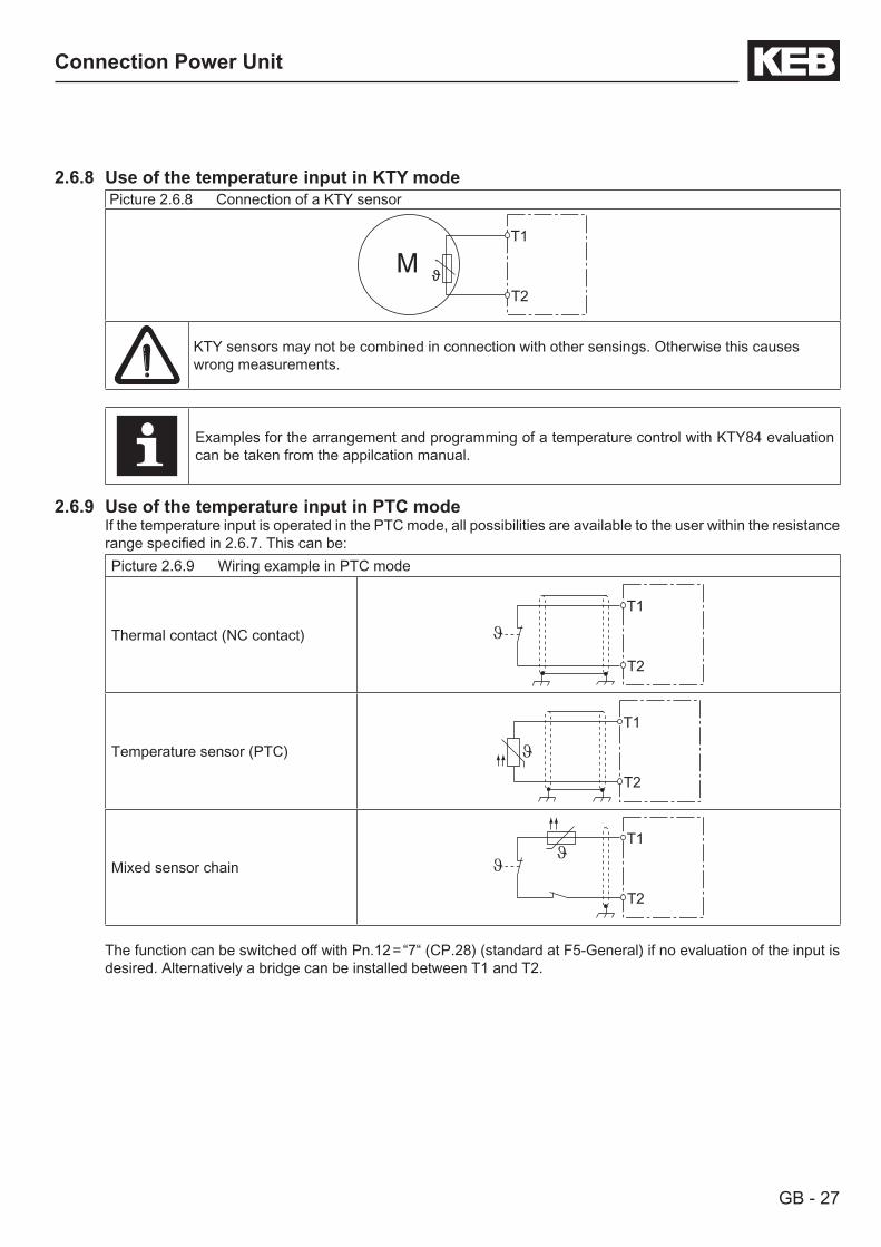
2.6.8 Use of the temperature input in KTY modePicture 2.6.8 Connection of a KTY sensor
T1
T2
KTY sensors may not be combined in connection with other sensings. Otherwise this causes wrong measurements.
Examples for the arrangement and programming of a temperature control with KTY84 evaluation can be taken from the appilcation manual.
2.6.9 Use of the temperature input in PTC modeIf the temperature input is operated in the PTC mode, all possibilities are available to the user within the resistance range specified in 2.6.7. This can be:Picture 2.6.9 Wiring example in PTC mode
Thermal contact (NC contact)
T1
T2
Temperature sensor (PTC)
T1
T2
Mixed sensor chain
T1
T2
The function can be switched off with Pn.12 = “7“ (CP.28) (standard at F5-General) if no evaluation of the input is desired. Alternatively a bridge can be installed between T1 and T2.
GB - 28
Connection Power Unit
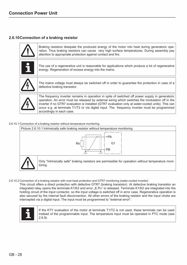
2.6.10 Connection of a braking resistor
Braking resistors dissipate the produced energy of the motor into heat during generatoric ope-ration. Thus braking resistors can cause very high surface temperatures. During assembly pay attention to appropriate protection against contact and fire.
The use of a regenerative unit is reasonable for applications which produce a lot of regenerative energy. Regeneration of excess energy into the mains.
The mains voltage must always be switched off in order to guarantee fire protection in case of a defective braking transistor.
The frequency inverter remains in operation in spite of switched off power supply in generatoric operation. An error must be released by external wiring which switches the modulation off in the inverter if no GTR7 evaluation is installed (GTR7 evaluation only at water-cooled units). This can occur e.g. at terminals T1/T2 or via digital input. The frequency inverter must be programmed accordingly in each case.
2.6.10.1 Connection of a braking resistor without temperature monitoringPicture 2.6.10.1 Intrinsically safe braking resistor without temperature monitoring
+PA
PB
RB G1
Only "intrinsically safe" braking resistors are permissible for operation without temperature moni-toring.
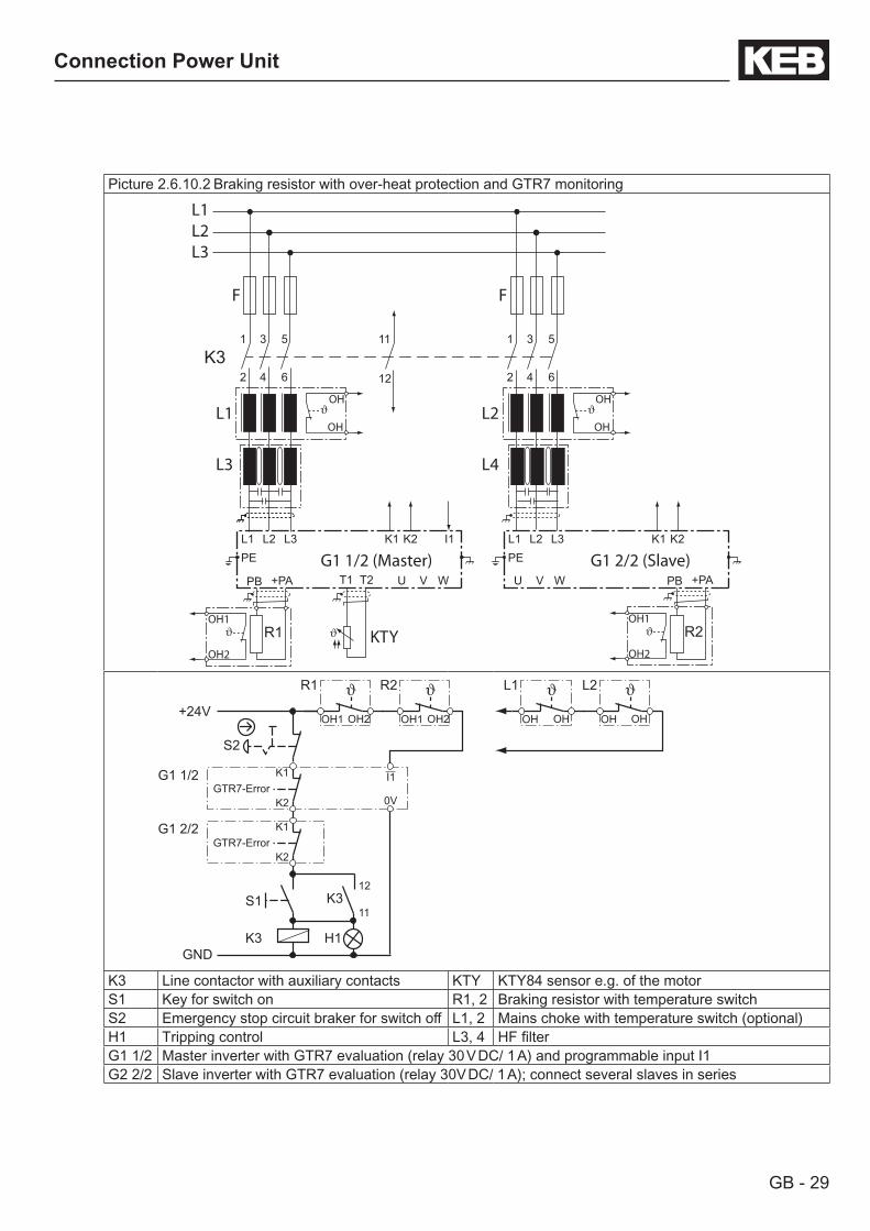
2.6.10.2 Connection of a braking resistor with over-heat protection and GTR7 monitoring (water-cooled inverter)This circuit offers a direct protection with defective GTR7 (braking transistor). At defective braking transistor an integrated relay opens the terminals K1/K2 and error „E.Pu“ is released. Terminals K1/K2 are integrated into the holding circuit of the input contactor, so the input voltage is switched off in error case. Regenerative operation is also secured by the internal fault disconnection. All other errors of the braking resistor and the input choke are intercepted via a digital input. The input must be programmed to "external error".
If the KTY evaluation of the motor at terminals T1/T2 is not used, these terminals can be used instead of the programmable input. The temperature input must be operated in PTC mode (see 2.6.9).
GB - 29
Connection Power Unit
Picture 2.6.10.2 Braking resistor with over-heat protection and GTR7 monitoring
2
U V W
L1 L2 K1 K2
T1 T2
L3
1
4
3
6
5
L1L2L3
K32
U V W
L1 L2 K1 K2L3
1
4
3
6
5
12
11
G1 1/2 (Master) G1 2/2 (Slave)
R1
+PAPB
OH1
OH2
R2
+PAPB
OH1
OH2
I1
OH
OH
OH
OH
PE PE
L1 L2
L3 L4
FF
KTY
+24V
S2
K1
K2GTR7-Error
K1 I1
K2GTR7-Error
G1 1/2
G1 2/2
K3GND
S1 K311
12
H1
0V
R1
OH2OH1
R2
OH2OH1
L1
OHOH
L2
OHOH
K3 Line contactor with auxiliary contacts KTY KTY84 sensor e.g. of the motorS1 Key for switch on R1, 2 Braking resistor with temperature switchS2 Emergency stop circuit braker for switch off L1, 2 Mains choke with temperature switch (optional)H1 Tripping control L3, 4 HF filterG1 1/2 Master inverter with GTR7 evaluation (relay 30 V DC/ 1 A) and programmable input I1G2 2/2 Slave inverter with GTR7 evaluation (relay 30V DC/ 1 A); connect several slaves in series

GB - 30
Connection Power Unit
2.6.10.3 Connection of a braking resistor with over-heat protection without GTR7 monitoring (air-cooled inverter)This circuit offers a direct protection with defective GTR7 (braking transistor). The braking resistor overheats and opens the OH terminals with defective GTR7. The OH terminals open the holding circuit of the input contactor, so that the input voltage is switched off in error case. An error in inverter is released by opening the auxiliary contacts of K3. Regenerative operation is also secured by the internal fault disconnection. The input must be programmed and inverted to "external error". Automatic restarting after cooling of the braking resistor is prevented by the self-holding circuit of K3.
If the KTY evaluation of the motor at terminals T1/T2 is not used, these terminals can be used instead of the programmable input. The temperature input must be operated in PTC mode (see 2.6.9).
Picture 2.6.10.3 Braking resistor with over-heat protection and GTR7 monitoring
2
U V W
L1 L2
T1 T2
L3
1
4
3
6
5
L1 L2 L3
K3 2
U V W
L1 L2 L3
1
4
3
6
5
12
11
14
13
G1 1/2 (Master) G1 2/2 (Slave)
R1
+PA PB
OH1
OH2
R2
+PA PB
OH1
OH2
I1 0V
OH
OH
OH
OH
PE PE
L1 L2
L3 L4
F F
KTY
further on next side
GB - 31
Connection Power Unit
+24V
S2
I1G1 1/2
K3 GND
S1 K3 11
12
H1
0V
R1
R2, L1, L2
OH2
OH1
OH2
OH1
K313
14
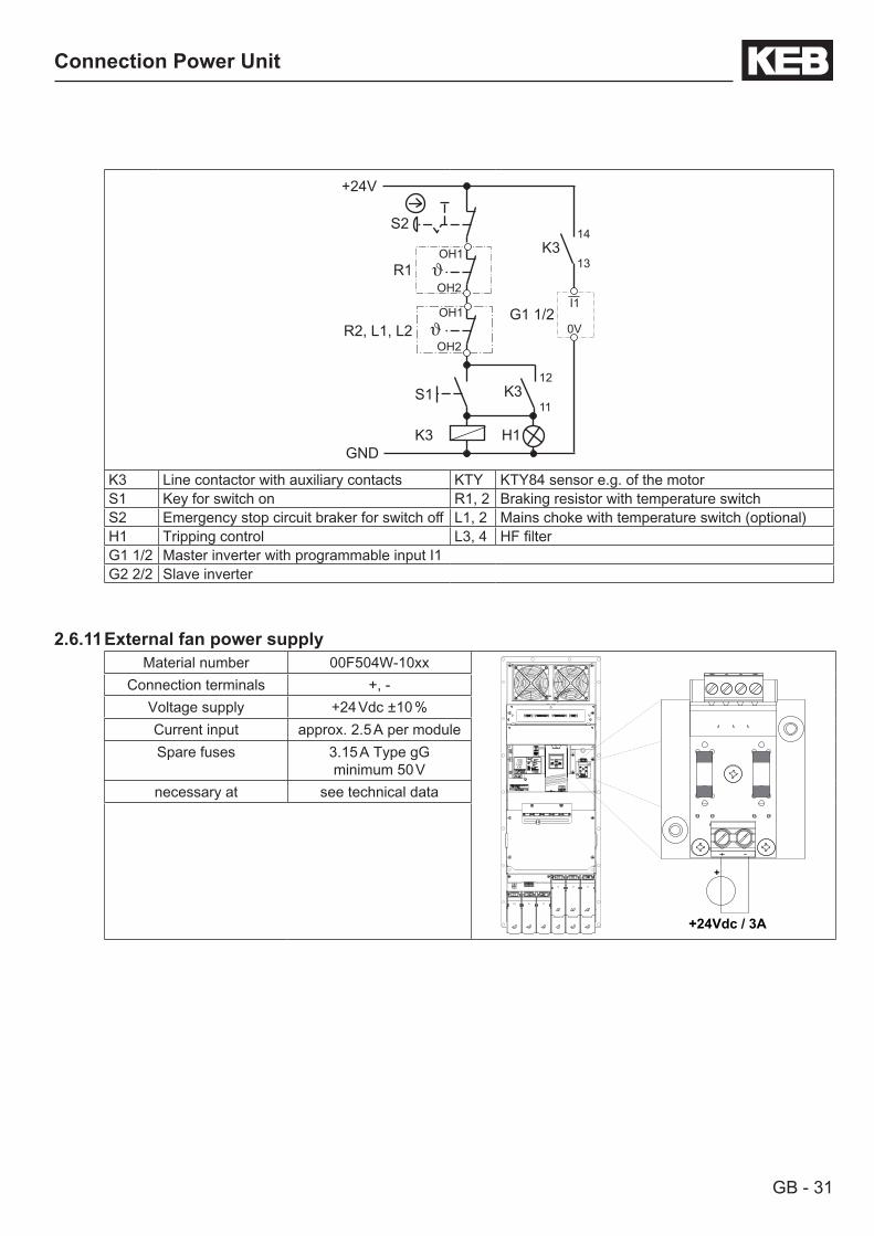
K3 Line contactor with auxiliary contacts KTY KTY84 sensor e.g. of the motorS1 Key for switch on R1, 2 Braking resistor with temperature switchS2 Emergency stop circuit braker for switch off L1, 2 Mains choke with temperature switch (optional)H1 Tripping control L3, 4 HF filterG1 1/2 Master inverter with programmable input I1G2 2/2 Slave inverter
2.6.11 External fan power supplyMaterial number 00F504W-10xx
14
13 12 11 10 5 4 3 2 1
15 16 17 18 19 20 21 22 23 24 25
9 8 7 6
14
13 12 11 10 5 4 3 2 1
15 16 17 18 19 20 21 22 23 24 25
9 8 7 65 4 3 2 1
9 8 7 6
5 4 3 2 1
9 8 7 6
5 4 3 2 1
9 8 7 6
5 4 3 2 1
9 8 7 6
+
+24Vdc / 3A
Connection terminals +, -Voltage supply +24 Vdc ±10 %Current input approx. 2.5 A per moduleSpare fuses 3.15 A Type gG
minimum 50 Vnecessary at see technical data
GB - 32
Connection Power Unit
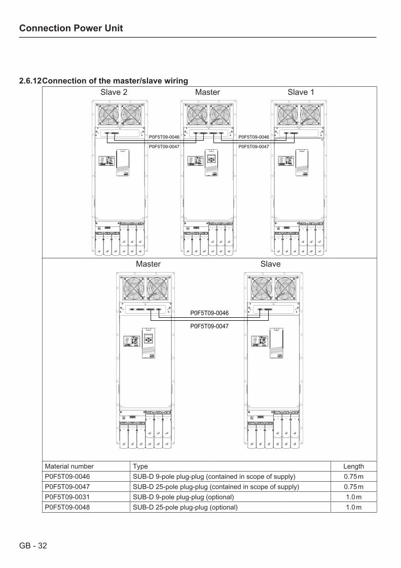
2.6.12 Connection of the master/slave wiringSlave 2 Master Slave 1
14
13 12 11 10 5 4 3 2 1
15 16 17 18 19 20 21 22 23 24 25
9 8 7 6
14
13 12 11 10 5 4 3 2 1
15 16 17 18 19 20 21 22 23 24 25
9 8 7 65 4 3 2 1
9 8 7 6
5 4 3 2 1
9 8 7 6
5 4 3 2 1
9 8 7 6
5 4 3 2 1
9 8 7 614
13 12 11 10 5 4 3 2 1
15 16 17 18 19 20 21 22 23 24 25
9 8 7 65 4 3 2 1
9 8 7 6
5 4 3 2 1
9 8 7 6 14
13 12 11 10 5 4 3 2 1
15 16 17 18 19 20 21 22 23 24 25
9 8 7 65 4 3 2 1
9 8 7 6
5 4 3 2 1
9 8 7 6
P0F5T09-0046
P0F5T09-0047
P0F5T09-0046
P0F5T09-0047
Master Slave
14
13 12 11 10 5 4 3 2 1
15 16 17 18 19 20 21 22 23 24 25
9 8 7 6
14
13 12 11 10 5 4 3 2 1
15 16 17 18 19 20 21 22 23 24 25
9 8 7 65 4 3 2 1
9 8 7 6
5 4 3 2 1
9 8 7 6
5 4 3 2 1
9 8 7 6
5 4 3 2 1
9 8 7 6 14
13 12 11 10 5 4 3 2 1
15 16 17 18 19 20 21 22 23 24 25
9 8 7 65 4 3 2 1
9 8 7 6
5 4 3 2 1
9 8 7 6
P0F5T09-0046
P0F5T09-0047
Material number Type LengthP0F5T09-0046 SUB-D 9-pole plug-plug (contained in scope of supply) 0.75 mP0F5T09-0047 SUB-D 25-pole plug-plug (contained in scope of supply) 0.75 mP0F5T09-0031 SUB-D 9-pole plug-plug (optional) 1.0 mP0F5T09-0048 SUB-D 25-pole plug-plug (optional) 1.0 m
GB - 33
Annex
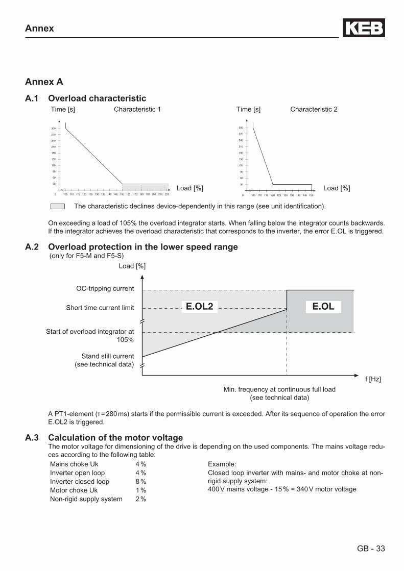
Annex AA.1 Overload characteristic
Time [s] Characteristic 1 Time [s] Characteristic 2
30
60
90
120
150
180
210
240
270
300
0 105 110 115 120 125 130 135 140 145 150 160 170 180 190 200 210 220
30
60
90
120
150
180
210
240
270
300
0 105 110 115 120 125 130 135 140 145 150
Load [%] Load [%]
The characteristic declines device-dependently in this range (see unit identification).
On exceeding a load of 105% the overload integrator starts. When falling below the integrator counts backwards. If the integrator achieves the overload characteristic that corresponds to the inverter, the error E.OL is triggered.
A.2 Overload protection in the lower speed range (only for F5-M and F5-S)
Load [%]
E.OL2 E.OL
OC-tripping current
Short time current limit
Start of overload integrator at 105%
Stand still current(see technical data)
f [Hz]Min. frequency at continuous full load
(see technical data)
A PT1-element (τ = 280 ms) starts if the permissible current is exceeded. After its sequence of operation the error E.OL2 is triggered.
A.3 Calculation of the motor voltageThe motor voltage for dimensioning of the drive is depending on the used components. The mains voltage redu-ces according to the following table: Mains choke Uk 4 % Example:Inverter open loop 4 % Closed loop inverter with mains- and motor choke at non-
rigid supply system:400 V mains voltage - 15 % = 340 V motor voltage
Inverter closed loop 8 %Motor choke Uk 1 %Non-rigid supply system 2 %
GB - 34
Annex
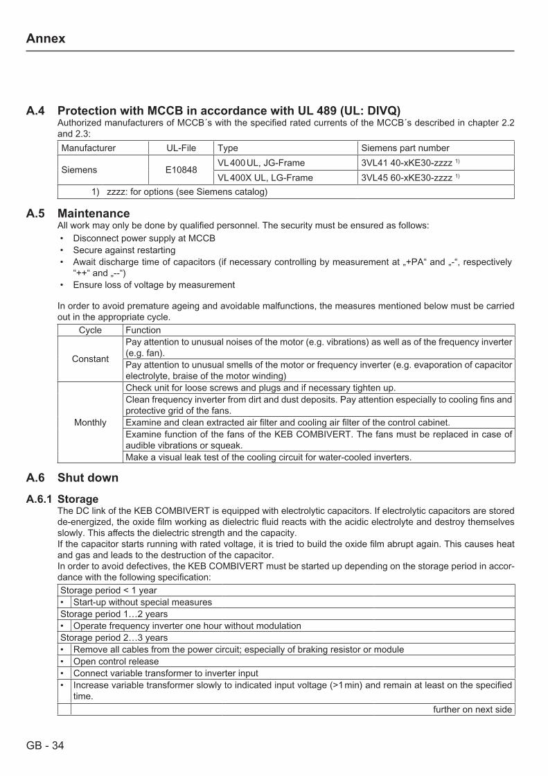
A.4 Protection with MCCB in accordance with UL 489 (UL: DIVQ)Authorized manufacturers of MCCB´s with the specified rated currents of the MCCB´s described in chapter 2.2 and 2.3:Manufacturer UL-File Type Siemens part number
Siemens E10848VL 400 UL, JG-Frame 3VL41 40-xKE30-zzzz 1)
VL 400X UL, LG-Frame 3VL45 60-xKE30-zzzz 1)
1) zzzz: for options (see Siemens catalog)
A.5 MaintenanceAll work may only be done by qualified personnel. The security must be ensured as follows:• Disconnect power supply at MCCB• Secure against restarting• Await discharge time of capacitors (if necessary controlling by measurement at „+PA“ and „-“, respectively
“++“ and „--“)• Ensure loss of voltage by measurement
In order to avoid premature ageing and avoidable malfunctions, the measures mentioned below must be carried out in the appropriate cycle.
Cycle Function
Constant
Pay attention to unusual noises of the motor (e.g. vibrations) as well as of the frequency inverter (e.g. fan).Pay attention to unusual smells of the motor or frequency inverter (e.g. evaporation of capacitor electrolyte, braise of the motor winding)
Monthly
Check unit for loose screws and plugs and if necessary tighten up.Clean frequency inverter from dirt and dust deposits. Pay attention especially to cooling fins and protective grid of the fans.Examine and clean extracted air filter and cooling air filter of the control cabinet.Examine function of the fans of the KEB COMBIVERT. The fans must be replaced in case of audible vibrations or squeak.Make a visual leak test of the cooling circuit for water-cooled inverters.
A.6 Shut down
A.6.1 StorageThe DC link of the KEB COMBIVERT is equipped with electrolytic capacitors. If electrolytic capacitors are stored de-energized, the oxide film working as dielectric fluid reacts with the acidic electrolyte and destroy themselves slowly. This affects the dielectric strength and the capacity. If the capacitor starts running with rated voltage, it is tried to build the oxide film abrupt again. This causes heat and gas and leads to the destruction of the capacitor.In order to avoid defectives, the KEB COMBIVERT must be started up depending on the storage period in accor-dance with the following specification:Storage period < 1 year• Start-up without special measuresStorage period 1…2 years• Operate frequency inverter one hour without modulationStorage period 2…3 years• Remove all cables from the power circuit; especially of braking resistor or module• Open control release• Connect variable transformer to inverter input• Increase variable transformer slowly to indicated input voltage (>1 min) and remain at least on the specified
time.further on next side
GB - 35
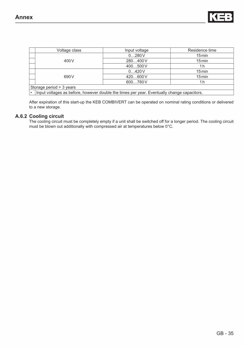
Annex
Voltage class Input voltage Residence time
400 V0…280 V 15 min
280…400 V 15 min400…500 V 1 h
690 V0…420 V 15 min
420…600 V 15 min600…760 V 1 h
Storage period > 3 years• Input voltages as before, however double the times per year. Eventually change capacitors.
After expiration of this start-up the KEB COMBIVERT can be operated on nominal rating conditions or delivered to a new storage.
A.6.2 Cooling circuitThe cooling circuit must be completely empty if a unit shall be switched off for a longer period. The cooling circuit must be blown out additionally with compressed air at temperatures below 0°C.
GB - 36
Annex
Annex BB.1 Certification
B.1.1 CE MarkingCE marked frequency inverter and servo drives were developed and manufactured to comply with the regulations of the Low-Voltage Directive 2006/95/EC.The inverter or servo drive must not be started until it is determined that the installation complies with the Machine directive (2006/42/EG) as well as the EMC-directive (2004/108/EC)(note EN 60204).The frequency inverters and servo drives meet the requirements of the Low-Voltage Directive 2006/95/EC. The harmonized standards of the series EN 61800-5-1 in connection with EN 60439-1 and EN 60146 were used.This is a product of limited availability in accordance with IEC 61800-3. This product may cause radio interference in residential areas. In this case the operator may need to take corresponding measures.
B.1.2 UL Marking
Acceptance according to UL is marked at KEB inverters with the adjacent logo on the type plate.
To be conform according to UL for the use on the North American and Canadian Market the following instructions must be observed (original text of the UL):• For control cabinet mounting as „Open Type“• Control Board Rating (max. 30Vdc, 1A)• Maximum Surrounding Air Temperature 45 °C (113 °F)• Overload protection at 130 % of inverter output rated current (see type plate)• Motor protection by adjustment of inverter parameters. For adjustement see application manual parameters
Pn.14 and Pn.15.• Suitable For Use On A Circuit Capable Of Delivering Not More Than 100k rms Symmetrical Amperes, 480
Volts Maximum“ and „When Protected by Class RK5 Fuses, rated xx Amperes or MVBs (DIVQ) as listed in Technical Data.
• Use 75°C Copper Conductors Only• Fan supply and Motor Thermal Protection Terminals - Torque Value for Field Wiring Terminals, the value to be
according to the R/C Terminal Block used.• Input/Output connections - “Input Studs and Nuts shall be connected with UL Listed Ring Connectors (ZMVV),
rated 600 V and suitable ampere rating (min. 125 % of Input Current)”. The tightening torque value of the Nuts needs to be 310 lb-inch (35 Nm).
• Use in a pollution degree 2 environment• ”Integral solid state short circuit protection does not provide branch circuit protection. Branch circuit protection
must be provided in accordance with the Manufacturer Instructions, National Electrical Code and any additio-nal local codes”, or the equivalent”.

GB - 37
Notice

GB - 38
Notice

GB - 39
Notice
KEB Antriebstechnik Austria GmbHRitzstraße 8 • A-4614 Marchtrenk
fon: +43 7243 53586-0 • fax: +43 7243 53586-21net: www.keb.at • mail: [email protected]
KEB AntriebstechnikHerenveld 2 • B-9500 Geraadsbergen
fon: +32 5443 7860 • fax: +32 5443 7898mail: [email protected]
KEB Power Transmission Technology (Shanghai) Co.,Ltd.No. 435 QianPu Road, Songjiang East Industrial Zone,
CHN-201611 Shanghai, P.R. Chinafon: +86 21 37746688 • fax: +86 21 37746600
net: www.keb.cn • mail: [email protected]
KEB Antriebstechnik Austria GmbHOrganizační složka
K. Weise 1675/5 • CZ-370 04 České Budějovicefon: +420 387 699 111 • fax: +420 387 699 119net: www.keb.cz • mail: [email protected]
KEB Antriebstechnik GmbH & Co. KGWildbacher Str. 5 • D–08289 Schneeberg
fon: +49 3772 67-0 • fax: +49 3772 67-281mail: [email protected]
KEB EspañaC/ Mitjer, Nave 8 - Pol. Ind. LA MASIA
E-08798 Sant Cugat Sesgarrigues (Barcelona)fon: +34 93 897 0268 • fax: +34 93 899 2035
mail: [email protected]
Société Française KEBZ.I. de la Croix St. Nicolas • 14, rue Gustave Eiffel
F-94510 LA QUEUE EN BRIEfon: +33 1 49620101 • fax: +33 1 45767495
net: www.keb.fr • mail: [email protected]
KEB (UK) Ltd.6 Chieftain Buisiness Park, Morris Close
Park Farm, Wellingborough GB-Northants, NN8 6 XFfon: +44 1933 402220 • fax: +44 1933 400724
net: www.keb-uk.co.uk • mail: [email protected]
KEB Italia S.r.l.Via Newton, 2 • I-20019 Settimo Milanese (Milano)
fon: +39 02 33535311 • fax: +39 02 33500790net: www.keb.it • mail: [email protected]
KEB Japan Ltd.15–16, 2–Chome, Takanawa Minato-ku
J–Tokyo 108-0074fon: +81 33 445-8515 • fax: +81 33 445-8215
mail: [email protected]
KEB Korea SeoulRoom 1709, 415 Missy 2000
725 Su Seo Dong, Gang Nam GuROK-135-757 Seoul/South Korea
fon: +82 2 6253 6771 • fax: +82 2 6253 6770mail: [email protected]
KEB RUS Ltd.Lesnaya Str. House 30, Dzerzhinsky (MO)
RUS-140091 Moscow regionfon: +7 495 632 0217 • fax: +7 495 632 0217
net: www.keb.ru • mail: [email protected]
KEB SverigeBox 265 (Bergavägen 19)
S-43093 Hälsöfon: +46 31 961520 • fax: +46 31 961124
mail: [email protected]
KEB America, Inc.5100 Valley Industrial Blvd. South
USA-Shakopee, MN 55379fon: +1 952 224-1400 • fax: +1 952 224-1499
net: www.kebamerica.com • mail: [email protected]
© KEBMat.No. 00F50EB-KP02
Rev. 1FDate 06/2009
More and newest addresses at http://www.keb.de
Karl E. Brinkmann GmbHFörsterweg 36-38 • D-32683 Barntrup
fon: +49 5263 401-0 • fax: +49 5263 401-116net: www.keb.de • mail: [email protected]
KEB worldwide…


![a fu titel gb - Electrónica Indústrialelectronicaindustrial.pt/application/uploads/files/00f5bemka02[1].pdf · 2 This manual describes the KEB COMBIVERT F5. Particular attention](https://img.pdfslide.us/doc/110x75/5b4310417f8b9ab15f8baa97/a-fu-titel-gb-electronica-industriale-1pdf-2-this-manual-describes-the.jpg)