Embed Size (px)
Citation preview
The sole responsibility for the content of this publication lies with the authors. It does not necessarily reflect the
opinion of the European Union. Neither the EACI nor the European Commission are responsible for any use that
may be made of the information contained therein.
CombiSol project
Solar Combisystems Promotion and Standardisation
D3.2 : Standards “Solar combisystem test methods”
B. Mette1), J. Ullmann1), H. Drück1)
M. Albaric2), Philippe Papillon2)
1) Institut für Thermodynamik und Wärmetechnik, Universität Stuttgart
Pfaffenwaldring 6, 70550 Stuttgart, Germany
Tel. +49 (0)711 685 63534; Fax: +49 (0)711 685 63232
E-mail address: [email protected]
2) CEA-INES
50 avenue du Lac Léman, 73377 Le Bourget du Lac, France
Tel. +33 (0)4 79 44 45 68; Fax: +33(0)4 79 62 13 74
E-mail address: [email protected]
Date 1/2011 Version FINAL Revision 1
Page 2 / 35
Contents 1 INTRODUCTION ....................................................................................................................................... 4
2 THE STANDARDS IN GENERAL ........................................................................................................... 4
2.1 CLASSIFICATION OF THERMAL SOLAR SYSTEMS.................................................................................... 5 2.2 TEST METHODS FOR SOLAR THERMAL SYSTEMS.................................................................................... 6
3 THE SCSPT METHOD AS A COMPLETE SYSTEM TEST APPROACH FOR SOLAR COMBISYSTEMS................................................................................................................................................ 7
APPENDIX: DRAFT STANDARD FOR CEN / TC 312................................................................................... 8
FOREWORD......................................................................................................................................................... 9
INTRODUCTION................................................................................................................................................. 9
1 SCOPE........................................................................................................................................................ 10
2 NORMATIVE REFERENCES ................................................................................................................ 10
3 TERMS AND DEFINITIONS.................................................................................................................. 11
4 SYMBOLS AND ABBREVIATIONS...................................................................................................... 11
5 TESTING ................................................................................................................................................... 12
5.1 FREEZE RESISTANCE........................................................................................................................... 12 5.2 HIGH TEMPERATURE PROTECTION......................................................................................................12
5.2.1 Scald protection ............................................................................................................................ 12 5.2.2 High temperature protection of materials ..................................................................................... 12
5.3 PRESSURE RESISTANCE....................................................................................................................... 13 5.4 WATER CONTAMINATION.................................................................................................................... 13 5.5 LIGHTNING PROTECTION..................................................................................................................... 13 5.6 SAFETY EQUIPMENT............................................................................................................................ 13
5.6.1 Safety valve.................................................................................................................................... 13 5.6.2 Safety lines and expansion lines .................................................................................................... 13 5.6.3 Blow-off lines ................................................................................................................................ 13
5.7 LABELING ........................................................................................................................................... 14 5.8 THERMAL PERFORMANCE CHARACTERIZATION.................................................................................. 14
5.8.1 Introduction................................................................................................................................... 14 5.8.2 Description of the tested system .................................................................................................... 14 5.8.3 Instruction with regards to the test facility.................................................................................... 14 5.8.4 Instructions with regards to the installation of the tested system.................................................. 18 5.8.5 Instructions with regards to the systems parameterization ........................................................... 20 5.8.6 Instruction with regards to the simulation tool ............................................................................. 20
5.9 TEST PROCEDURE............................................................................................................................... 21 5.9.1 System conditioning....................................................................................................................... 21 5.9.2 Primary conditioning .................................................................................................................... 22 5.9.3 Secondary conditioning................................................................................................................. 22 5.9.4 Test sequence ................................................................................................................................ 22 5.9.5 Storage discharge.......................................................................................................................... 22 5.9.6 Thermal performance presentation sheet ...................................................................................... 25
5.10 REVERSE FLOW PROTECTION.............................................................................................................. 25 5.11 ELECTRIC SAFETY............................................................................................................................... 25
ANNEX A ............................................................................................................................................................ 25
ANNEX B............................................................................................................................................................. 25

Page 3 / 35
ANNEX C ............................................................................................................................................................ 26
ANNEX D ............................................................................................................................................................ 35
ANNEX E............................................................................................................................................................. 36
Page 4 / 35
1 Introduction
Within the work of the CombiSol project two laboratory test methods for testing solar combisystems have been experimentally and theoretically investigated and assessed. The first test method is the CTSS method (CTSS: component testing – system simulation), which consists of a physical test of the main components of the solar combisystems and on an annual system simulation in order to determine the annual system performance. The thermal performance tests of the main components are conducted according to the technical specification CEN/TS 12977-2:2010. The standard CEN/TS 12977 is currently under development and it is expected that in 2012 it will become a status of a European standard. The second test method, the SCSPT method (SCSPT: short cycle system performance test), consists of a physical test of the complete system (excluding the collector field). In order to determine the thermal performance of the system, the system is operated during several days according to defined test sequences. Within the physical test the energy fluxes to and from the system are recorded. The annual system performance is predicted by extrapolating the test results to a complete year. For this testing approach no standard has been elaborated yet. Three different designs of solar combisystems have been tested according to these test method. The testing according to the CTSS method has been performed at the Institute of Thermodynamics and Thermal Engineering (ITW) at the University of Stuttgart, Germany, the testing according to the SCSPT method has been performed at the Institut National de l’Energie Solaire (INES), Bourget du Lac, France. For the comparison of the test methods, two of the three systems have been tested according to both test methods. A detailed description of the CTSS method and SCSP method, the results of the thermal performance test and a comparison of the test methods, is given in the report “D3.1: Comparison of test methods”. This report gives a short overview of existing testing standards. A draft for CEN/TC 312, which has been prepared by INES within the CombiSol project, is attached as annex. It describes a test method for the determination of the primary energy savings of solar combisystem based on the SCSPT method.
2 The standards in general
The existing CEN/TC 312 standard covers both test methods for solar domestic hot water system and for solar combisystem. An overview of the CEN/TC 312 standards is given in Table 2.1.
Table 2.1: Titles of the CEN/TC 312 standard
Number Title “Thermal solar systems and components-…”
EN 12975-1 Collectors. Part 1: General Requirements
EN 12975-2 Collectors – Part 2: Test Methods
Page 5 / 35
EN 12976-1 Factory Made Systems. Part 1: General Requirements
EN 12976-2 Factory Made Systems. Part 2: Test Methods
CEN/TS 12977-1* Custom Built Systems. Part 1: General Requirements for solar water heaters and combisystems
CEN/TS 12977-2* Custom Built Systems. Part 2: Test Methods for solar water heaters and combisystems
EN 12977-3* Custom Built Systems. Part 3: Performance test methods for solar water heater stores
CEN/TS 12977-4* Custom Built Systems. Part 4: Performance test methods for solar combisystems
CEN/TS 12977-5* Custom built systems. Part 5: Performance test methods for control equipment
*) It is expected that the CEN/TS “pre-standards” will be published as European Standards (ENs) during 2011.
2.1 Classification of thermal solar systems As can be seen from the title of the standards, the thermal solar systems have been divided into two groups: “factory made systems” and “custom built systems”. This division is necessary in order to be able to include the whole spectrum of thermal solar systems used in Europe, which ranges from small compact systems (thermosiphon and integrated collector-storage-systems) to very large systems individually designed by engineers. The classification of a system as factory made or custom built is a choice of the final supplier in accordance to the following definitions:
Factory made solar heating systems are batch products with one trade name, sold as complete and ready to install kits, with fixed configuration. Systems of this class are considered as a single product and assessed as a whole. For the determination of its thermal performance, such a system is tested as one complete unit. If a factory made solar heating system is modified by changing its configuration or by changing one or more of its components, the modified system is considered as a new system for which a new test report is necessary. Custom built solar heating systems are either uniquely built or assembled by choosing from an assortment of components. Systems of this category are regarded as a set of components. The components are separately tested and test results are integrated to an assessment of the whole system. Custom built solar heating systems are subdivided into two categories:
• Large custom built systems are uniquely designed for a specific situation. In general HVAC engineers, manufacturers or other experts design them (HVAC: heating, ventilation, air-conditioning).
• Small custom built systems offered by a company are described in a so called assortment file, in which all components and possible system configurations, marketed by the company, are specified. Each possible combination of a system configuration with components from the assortment is considered as one custom built system.
Page 6 / 35
The different types of thermal solar systems are summarised in Table 2. As a consequence of this way of classification forced circulation systems can be considered either as factory made or as custom built, depending on the market approach chosen by the final supplier. As a consequence of this, it is essential that the performance of these systems is determined for the same set of reference conditions as specified in annex B of EN 12976-2 and annex A of CEN/TS 12977-2. Table 2.2: Division for factory made and custom built thermal solar systems
Factory Made Solar Heating Systems (EN 12976-1, -2)
Custom Built Solar Heating Systems (CEN/TS 12977-1, -2, -4, -5, EN 12977-3)
Integral collector-storage systems for domestic hot water preparation
Thermosiphon systems for domestic hot water preparation
Forced-circulation systems for hot water preparation and/or space heating, assembled using components and configurations described in a documentation file (mostly small systems)
Forced-circulation systems as batch product with fixed configuration for domestic hot water preparation
Uniquely designed and assembled systems for hot water preparation and/or space heating (mostly large systems)
2.2 Test methods for solar thermal systems Testing standard exist for both solar domestic hot water systems and solar combisystems. Solar domestic hot water systems can be tested according to EN 12976 as factory made systems and / or CEN/TS 12977-2 as custom built system. Solar combisystem can only be tested according to CEN/TS 12977-2 (CTSS method) as custom built system. The thermal performance of factory made systems is determined according to EN 12976-2 either by applying the DST-method (DST = Dynamic System Test, see ISO / DIS 9459-5) or by using the CSTG-method (CSTG = Complete System Testing Group, see ISO 9459-2). For both test procedures, the whole thermal solar system is installed on a test facility and operated under natural climate conditions according to well defined test sequences. The aim of both test procedures is to determine the annual system performance for specified reference conditions on the basis of short term tests. For the determination of the thermal performance of small custom built systems according to CEN/TS 12977-2, the CTSS method has to be used. The CTSS method is based on a separate test of the most important components: The heat store or combistore is tested according to EN 12977-3 or CEN/TS 12977-4:2010, respectively, the controller according to CEN/TS 12977-5:2010 and the collector according to EN 12975-2:2006. Based on the parameters determined for the different components the thermal performance of the complete system is predicted by using a component based system simulation program (e.g. TRNSYS).

Page 7 / 35
3 The SCSPT method as a complete system test approa ch for solar combisystems
With the SCSPT method the thermal performance of a solar combisystem is determined by testing the system as complete unit (excluding the collector field). This test method is a useful completion to the already existing testing standard for solar combisystems (CEN/TS 12977-2). As it is the case for solar domestic hot water systems, where two different testing approaches for the determination of the thermal performance exist, the SCSPT method could be an alternative to the CTSS method for prefabricated solar combisystems. These combisystems can be categorized as “Factory Made Solar Heating Systems” (cf. Table 2.1). For the SCSPT the whole combisystem (excluding the collector field) is mounted on an indoor test facility and tested according to a defined test sequence. The system installation also includes the auxiliary heater and the piping in between the system components. During the physical test of the system, the heating load of the building and the energy gain from the collector field are computed with a simulation software and emulated by a cooling and heating circuit. According to the control strategy of the combisystem the mass flow rate and flow temperature in the collector circuit, space heating circuit and auxiliary heater circuit are adapted. The domestic hot water draw-off is performed according to a load file in which the corresponding hot and cold water temperatures and mass flow rates are specified. For the determination of the annual system performance, the measured test results (energy fluxes to and from the system: heat demand for space heating and domestic hot water, solar energy gain in the collector circuit, auxiliary fuel consumption and parasitic electrical energy consumption) are extrapolated to a complete year. The SCSPT method sets its focus on the performance of the whole heating system. A central element of the testing is to take into account the overall control strategy of the combisystem and hence the interaction of the different hydraulic circuits. As the auxiliary boiler is part of the system test, it also allows for analyzing the dynamic behavior of the boiler in operation. As the SCSPT method is not standardized yet, within the combisol project a draft for CEN/TC 312 describing the SCSPT method has been prepared by INES. In the annex a draft of the standard is given.
Page 8 / 35
APPENDIX: Draft standard for CEN / TC 312
Draft standard for CEN / TC 312 Thermal solar system and components – Factory made solar combisystem – General requirements and test method
Prepared by: CEA-INES 50 avenue du Lac Léman, 73377 Le Bourget du Lac, France Tel. +33 (0)4 79 44 45 68; Fax: +33(0)4 79 62 13 74 E-mail address: [email protected]
Page 9 / 35
Foreword This document has been prepared by Institut National de l’Energie Solaire (INES), Bourget du Lac, France.
Introduction Drinking water quality In respect of potential adverse effects on the quality of water intended for human consumption, caused by the product covered by this document it should be noted that:
• this document provides no information as to whether the product may be used without restriction in any of the Member States of the EU or EFTA;
• while awaiting the adoption of verifiable European criteria, existing national regulations concerning the use and/or the characteristics of this product remain in force.
Factory Made and Custom Built solar heating systems EN 12976-1, EN 12976-2 and prCEN/TS 12977-1 to -5, distinguish two categories of solar heating systems:
• Factory Made solar heating systems and • Custom Built solar heating systems.
The classification of a system as Factory Made or Custom Built is a choice of the final supplier, in accordance to the following definitions: 1) Factory Made solar heating systems are batch products with one trade name, sold as complete and ready to install kits, with fixed configurations. Systems of this category are considered as a single product and assessed as a whole. If a Factory Made Solar Heating System is modified by changing its configuration or by changing one or more of its components, the modified system is considered as a new system for which a new test report is necessary. Requirements and test methods for Factory Made solar heating systems are given in EN 12976-1 and EN 12976-2. 2) Custom Built solar heating systems are either uniquely built or assembled by choosing from an assortment of components. Systems of this category are regarded as a set of components. The components are separately tested and test results are integrated to an assessment of the whole system. Requirements for Custom Built solar heating systems are given in prCEN/TS 12977-1, test methods are specified in prCEN/TS 12977-2 to -5. Custom Built solar heating systems are subdivided into two categories:
• Large Custom Built systems are uniquely designed for a specific situation. In general they are designed by HVAC engineers, manufacturers or other experts.
Page 10 / 35
• Small Custom Built systems offered by a company are described in a so called assortment file, in which all components and possible system configurations, marketed by the company, are specified. Each possible combination of a system configuration with components from the assortment is considered as one Custom Built system.
1 Scope
This document applies to solar heating systems and gives test methods for verification of the requirements specified in prCEN/TS 12977-1. This document includes also a method for thermal performance characterization and system performance prediction of systems by means of component testing and system simulation.
2 Normative references
The following referenced documents are indispensable for the application of this document. For dated references, only the edition cited applies. For undated references, the latest edition of the referenced document (including any amendments) applies. EN 12975-1:2006, Thermal solar systems and components — Solar collectors — Part 1: General Requirements EN 12975-2:2006, Thermal solar systems and components — Solar collectors — Part 2: Test methods EN 12976-1:2006, Thermal solar systems and components — Factory made systems — Part 1: General requirements EN 12976-2:2006, Thermal solar systems and components — Factory made systems — Part 2: Test methods prCEN/TS 12977-1, Thermal solar systems and components — Custom built systems — Part 1: General requirements for solar heaters and combisystems prEN 12977-3, Thermal solar systems and components — Custom built systems — Part 3: Performance test methods for solar water heater stores prCEN/TS 12977-4, Thermal solar systems and components — Custom built systems — Part 4: Performance test methods for solar combistores prCEN/TS 12977-5, Thermal solar systems and components — Custom built systems — Part 5: Performance test methods for controllers EN 60335-1:2002, Household and similar electrical appliances — Safety — Part 1: General requirements
Page 11 / 35
EN 60335-2-21:2003, Safety of household and similar electrical appliances — Part 2: Particular requirements for storage water heaters ISO 9459-5, Solar heating — Domestic water heating systems — Part 5: System performance by means of whole system testing and computer simulation EN ISO 9488, Solar energy — Vocabulary
3 Terms and definitions
For the purposes of this document, the terms and definitions given in EN 12975-1, EN 12976-1, prCEN/TS 12977-1, prEN 12977-3, prCEN/TS 12977-4 to -5, ISO 9459-5 and EN ISO 9488 apply.
4 Symbols and abbreviations
Symbol Definition Unit
BL boiler hydraulic circuit
CL solar collector hydraulic circuit
DHW domestic hot wtare
Eaux,elec parasitic energy kWh
Eaux,gaz primary energy kWh
Eaux,glob net primary energy kWh
Eaux,predit extrapoletd annual auxiliary energy kWh
Egaz,PCI auxiliary energy for gas boiler based on low calorific value kWh
Egaz,PCS auxiliary energy for gas boiler based on high calorific value kWh
Ei energy for hydraulic circuit i kWh
Epenalty penalty function kWh
Epenalty,H penalty function for the heating circuit kWh
Epenalty,DHW penalty function for the domestic hot water circuit kWh
Epassive gain passive gain kWh
fsav fractional energy savings %
Page 12 / 35
fsav,gaz primary energy saving %
fsav,glob net primary energy saving %
HL space heating hydraulic circuit
Qaux,net net auxiliary energy demand of the solar heating system delivered by the auxiliary heater to the store or directly to the heat distribution system
kWh
Qd heat demand kWh
QL energy delivered at the outlet of the solar heating system kWh
Qpar parasitic energy (electricity) and control unit kWh
Qsol energy delivered by the collector loop to the store kWh
ST tested system
5 Testing
5.1 Freeze resistance See EN 12976-2
5.2 High temperature protection
5.2.1 Scald protection If the temperature of the domestic hot water in the system can exceed 60 °C, the assembly instruction shall mention that an automatic cold water mixing device or any other device to limit the tapping temperature to at most 60 °C shal l be installed on the solar system or elsewhere in the domestic hot water installation. Cf. EN12977-2, 6.1.4.1
5.2.2 High temperature protection of materials The system shall have been designed in such a way that the maximal allowed temperature of any material in the system is never exceeded Cf. EN12977-2, 6.1.4.2 NOTE: Both transients (high-temperature peaks of short duration) and stagnation of longer duration may create adverse conditions for the respective material.

Page 13 / 35
5.3 Pressure resistance In case that it is not documented that the store(s) and the heat exchanger(s) withstand at least 1.5 times the manufacturer’s stated maximum individual working pressures, the procedures specified in EN 12976-2:2006, 5.3 should be applied on the store(s) and the heat exchanger(s). NOTE EN 12976-2:2006, 5.3, specifies a pressure resistance test method for a complete thermal solar system. For the purpose of this clause this method has to be applied on the store(s) and heat exchanger(s) principally. Check if the system documentation for the installer describes a pressure resistance test procedure for the system.
5.4 Water contamination Check the design of all circuits to avoid water contamination due to backflow from all circuits to drinking main supplies. The system shall conform to EN 1717.
5.5 Lightning protection Verify the compliance with the requirements given in prCEN/TS 12977-1: paragraph 6.5.2 by checking the documentation included in prCEN/TS 12977-1: paragraph 6.7.3
5.6 Safety equipment
5.6.1 Safety valve The safety valve shall conform to prCEN/TS 12977-1: paragraph 6.4.1
5.6.2 Safety lines and expansion lines If the system is equipped with a safety line, this safety line shall not be capable of being shut off. If the system is equipped with a safety line and an expansion line, the safety line and expansion line shall be dimensioned such, that for the highest flow of hot water or steam that can occur, at no place in the collector loop the maximum allowed pressure is exceeded due to the pressure drop in these lines. The dimension of the safety line and expansion line shall be proved by suitable means. The expansion line and the safety line shall be connected and laid in such a way that any accumulations of dirt, scale or similar impurities are avoided.
5.6.3 Blow-off lines
Page 14 / 35
Check the hydraulic scheme and system documentation to verify that the blow-off lines fulfill the requirements given in prCEN/TS 12977-1: paragraph 6.4.3
5.7 Labeling Check the Marking plate or Label of the Solar heating system and examine if all items of the labeling list are completed (as specified in 4.7 of EN 12976-1:2005)
5.8 Thermal performance characterization
5.8.1 Introduction The solar combisystem thermal performance test aims to forecast the auxiliary energy consumption for a defined climate and heat demands (Domestic hot water and space heating). The dynamic test of solar combisystems is realized in a semi virtual environment where the solar load, the DHW and the space heating demands are emulated. The test bench used, the testing condition and the methodology used are presented in the following paragraph.
5.8.2 Description of the tested system The tested system (designate as ST in the following document) integrates all the hydraulic and electrical components used within the installation. The boundaries of the ST are defined by:
• flow/return pipes of the solar circuit • flow/return pipes of the heating circuit • Fresh water pipe • DHW pipes • Auxiliary energy device • Auxiliary electrical device
5.8.3 Instruction with regards to the test facility
5.8.3.1 General
The ST has to be tested with in a specific test facility The test facility is composed to minimum:
• One hydraulic circuit dedicated to emulate the solar collector (CL) • One hydraulic circuit dedicated to emulate the space heating loop (HL) • One hydraulic circuit dedicated to emulate DHW draw-off with the possibility to set the
fresh water temperature • One electric meter able to record parasitic consumption
Depending on the auxiliary energy device used, some complements have to be added:
Page 15 / 35
Type of auxiliary energy device used Complements needed
None One hydraulic circuit dedicated to emulate the boiler (BL)
Gas generator Gas measuring, continuous high calorific value recording
Electrical joule generator Electric meter
Oil generator Oil measuring
Wood generator Calorific value and quantity of the wood used
Electrical heat pump generator One circuit dedicated to emulate the cold source and one electric meter
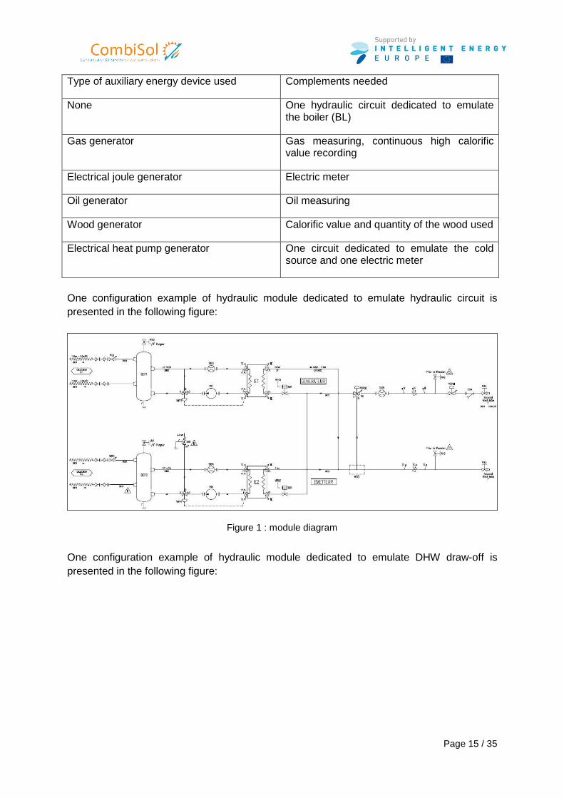
One configuration example of hydraulic module dedicated to emulate hydraulic circuit is presented in the following figure:
Figure 1 : module diagram
One configuration example of hydraulic module dedicated to emulate DHW draw-off is presented in the following figure:
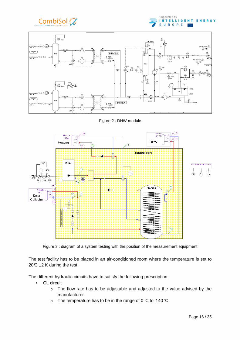
Page 16 / 35
Figure 2 : DHW module
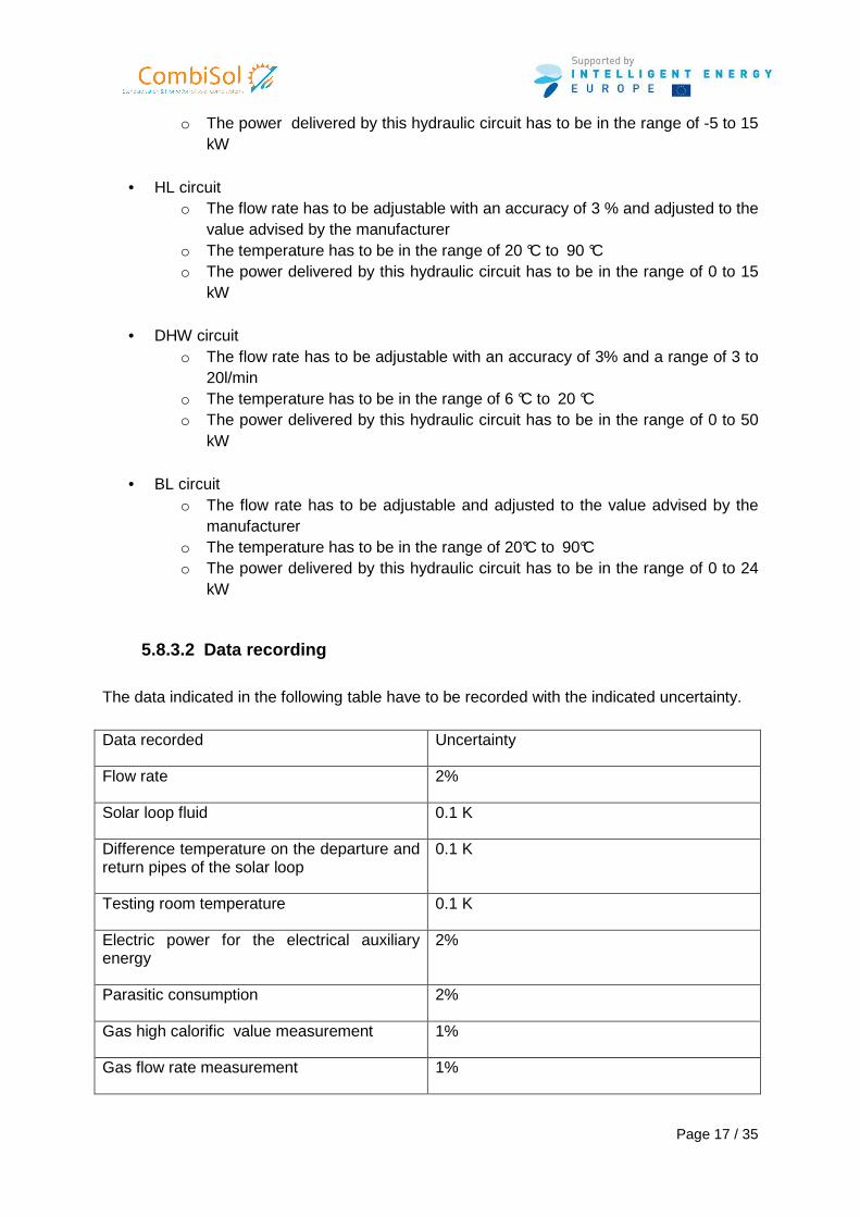
Solar hydraulic module
Figure 3 : diagram of a system testing with the position of the measurement equipment
The test facility has to be placed in an air-conditioned room where the temperature is set to 20°C ±2 K during the test. The different hydraulic circuits have to satisfy the following prescription:
• CL circuit o The flow rate has to be adjustable and adjusted to the value advised by the
manufacturer o The temperature has to be in the range of 0 °C to 140 °C
Page 17 / 35
o The power delivered by this hydraulic circuit has to be in the range of -5 to 15 kW
• HL circuit
o The flow rate has to be adjustable with an accuracy of 3 % and adjusted to the value advised by the manufacturer
o The temperature has to be in the range of 20 °C to 90 °C o The power delivered by this hydraulic circuit has to be in the range of 0 to 15
kW
• DHW circuit o The flow rate has to be adjustable with an accuracy of 3% and a range of 3 to
20l/min o The temperature has to be in the range of 6 °C to 20 °C o The power delivered by this hydraulic circuit has to be in the range of 0 to 50
kW
• BL circuit o The flow rate has to be adjustable and adjusted to the value advised by the
manufacturer o The temperature has to be in the range of 20°C to 90°C o The power delivered by this hydraulic circuit has to be in the range of 0 to 24
kW
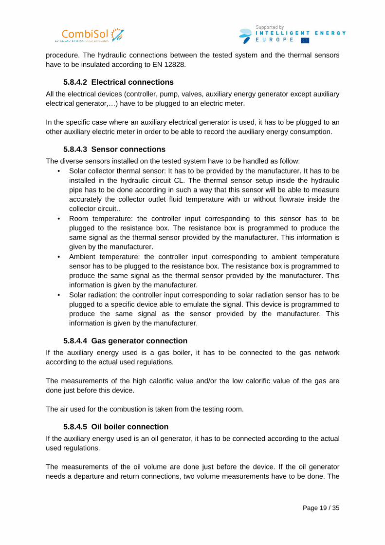
5.8.3.2 Data recording
The data indicated in the following table have to be recorded with the indicated uncertainty. Data recorded Uncertainty
Flow rate 2%
Solar loop fluid 0.1 K
Difference temperature on the departure and return pipes of the solar loop
0.1 K
Testing room temperature 0.1 K
Electric power for the electrical auxiliary energy
2%
Parasitic consumption 2%
Gas high calorific value measurement 1%
Gas flow rate measurement 1%
Page 18 / 35
Oil flow rate measurement 1%
Resistance box 0.05%
The data have to be recorded every 1 minute. The relaxation time of the thermal sensors has to be lower than 10 seconds.
5.8.4 Instructions with regards to the installation of the tested system The tested system has to be installed on the test facility according to the manufacturer instructions
5.8.4.1 Hydraulic connections
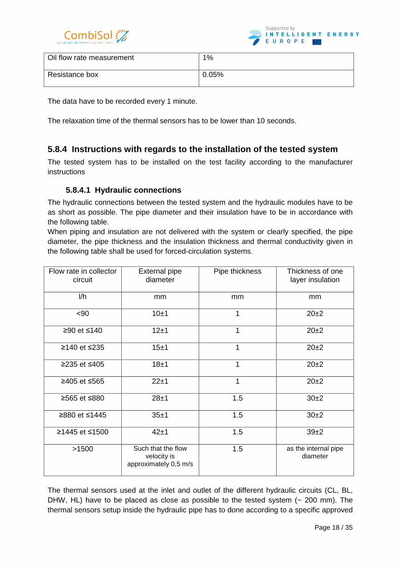
The hydraulic connections between the tested system and the hydraulic modules have to be as short as possible. The pipe diameter and their insulation have to be in accordance with the following table. When piping and insulation are not delivered with the system or clearly specified, the pipe diameter, the pipe thickness and the insulation thickness and thermal conductivity given in the following table shall be used for forced-circulation systems. Flow rate in collector
circuit External pipe
diameter Pipe thickness Thickness of one
layer insulation
l/h mm mm mm
<90 10±1 1 20±2
≥90 et ≤140 12±1 1 20±2
≥140 et ≤235 15±1 1 20±2
≥235 et ≤405 18±1 1 20±2
≥405 et ≤565 22±1 1 20±2
≥565 et ≤880 28±1 1.5 30±2
≥880 et ≤1445 35±1 1.5 30±2
≥1445 et ≤1500 42±1 1.5 39±2
>1500 Such that the flow velocity is
approximately 0,5 m/s
1.5 as the internal pipe diameter
The thermal sensors used at the inlet and outlet of the different hydraulic circuits (CL, BL, DHW, HL) have to be placed as close as possible to the tested system (~ 200 mm). The thermal sensors setup inside the hydraulic pipe has to done according to a specific approved
Page 19 / 35
procedure. The hydraulic connections between the tested system and the thermal sensors have to be insulated according to EN 12828.
5.8.4.2 Electrical connections
All the electrical devices (controller, pump, valves, auxiliary energy generator except auxiliary electrical generator,…) have to be plugged to an electric meter. In the specific case where an auxiliary electrical generator is used, it has to be plugged to an other auxiliary electric meter in order to be able to record the auxiliary energy consumption.
5.8.4.3 Sensor connections
The diverse sensors installed on the tested system have to be handled as follow: • Solar collector thermal sensor: It has to be provided by the manufacturer. It has to be
installed in the hydraulic circuit CL. The thermal sensor setup inside the hydraulic pipe has to be done according in such a way that this sensor will be able to measure accurately the collector outlet fluid temperature with or without flowrate inside the collector circuit..
• Room temperature: the controller input corresponding to this sensor has to be plugged to the resistance box. The resistance box is programmed to produce the same signal as the thermal sensor provided by the manufacturer. This information is given by the manufacturer.
• Ambient temperature: the controller input corresponding to ambient temperature sensor has to be plugged to the resistance box. The resistance box is programmed to produce the same signal as the thermal sensor provided by the manufacturer. This information is given by the manufacturer.
• Solar radiation: the controller input corresponding to solar radiation sensor has to be plugged to a specific device able to emulate the signal. This device is programmed to produce the same signal as the sensor provided by the manufacturer. This information is given by the manufacturer.
5.8.4.4 Gas generator connection
If the auxiliary energy used is a gas boiler, it has to be connected to the gas network according to the actual used regulations. The measurements of the high calorific value and/or the low calorific value of the gas are done just before this device. The air used for the combustion is taken from the testing room.
5.8.4.5 Oil boiler connection
If the auxiliary energy used is an oil generator, it has to be connected according to the actual used regulations. The measurements of the oil volume are done just before the device. If the oil generator needs a departure and return connections, two volume measurements have to be done. The
Page 20 / 35
uncertainties of the measurements have to be two time lower than the uncertainty of the previous table in paragraph 5.8.3.2 The air used for the combustion is taken in the testing room.
5.8.5 Instructions with regards to the systems para meterization Before the start of the physical test, a complete system setup is realized. When the test begins, the clock of the controller has to be synchronized with the simulation.
5.8.6 Instruction with regards to the simulation to ol The different emulated circuits have to satisfy the following instructions.
5.8.6.1 Principle, nature and type of the simulatio n system
A control/command of the emulated hydraulic loops has to be able to realize the following operations:
• Temperature and flow rate data record at the inlet of the hydraulic module • Data transfer (temperature and flow rate) to the simulation software. This simulation
software has to be supplied by the climatic data if necessary. • Computation of the outlet temperature of the hydraulic module and control the
hydraulic module in order to reach this temperature value. • Control of the resistance box in order to give right information to the system tested.
The climatic environment of the tested system, the solar collectors, the heating loads and the domestic hot water draw-off are simulated using a dynamical simulation tool. The time step for the control/command and the time step of the simulation tool has to be set to 1 min.
5.8.6.2 Reference conditions
5.8.6.2.1 Climatic reference conditions The test sequence is performed under Zurich climate. The data are given in the annex A.
5.8.6.2.2 Domestic hot water draw-off The DHW draw-off uses a specific data file. The DHW consumption is 100 kWh for the 12 days. The data file and the evolution of the fresh water are given in the annex B.
5.8.6.2.3 Heating load
The reference heating loads used are 60 kWh/(m2.an) for Zurich climate. The model used for the heating load is given in the annex C.
5.8.6.2.4 Reference heating transmitter
Page 21 / 35
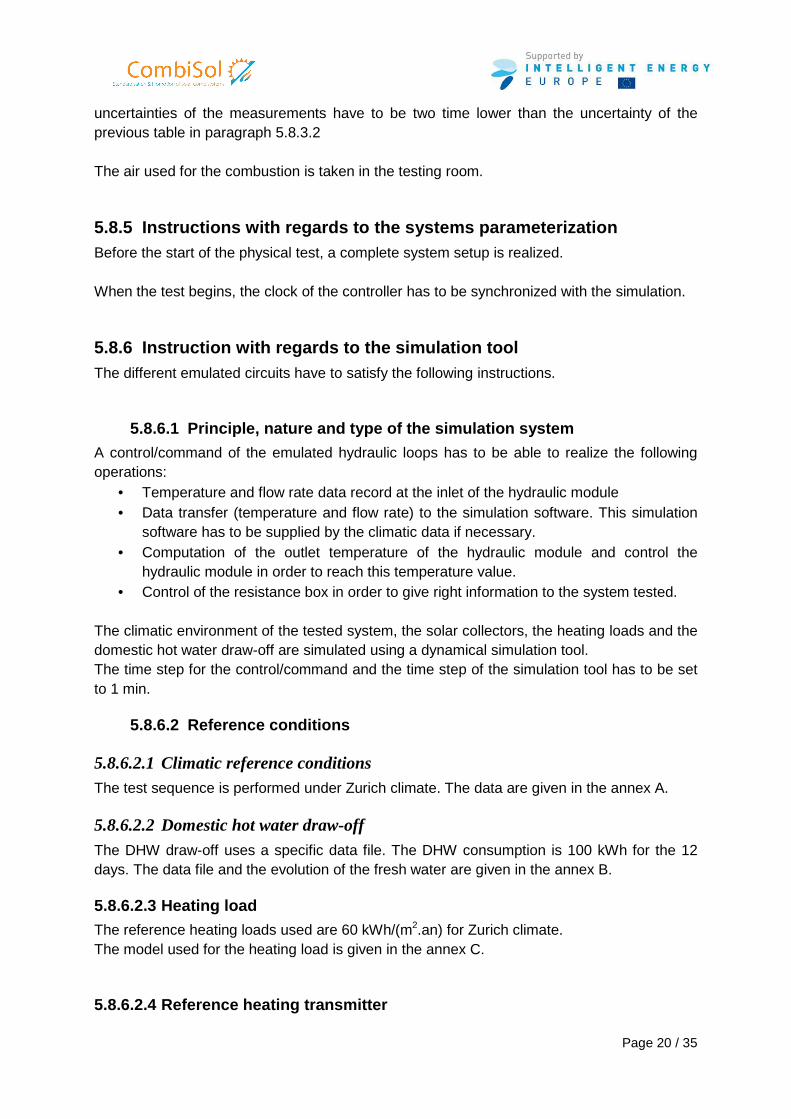
According to the manufacturer instructions, different type of transmitter can be used: • Radiator • Heating floor
The manufacturer choice is mentioned on the test report. The sizings of such transmitters are done according to the climatic reference conditions:
• Ambient outside temperature: -10°C • Room temperature set up: 20°C
Inlet temperature Flow rate Power
Radiator 40°C 792 l/h 4.6 kW
Heating floor 38°C 500 l/h
The equations of the model used for these transmitters are given in the annex D.
5.8.6.2.5 Solar collectors
The solar collectors are modeled according to EN 12975. The parameters of the solar collector used are given in the following annex E. The collector area is given by the manufacturer and is mentioned in the test report.
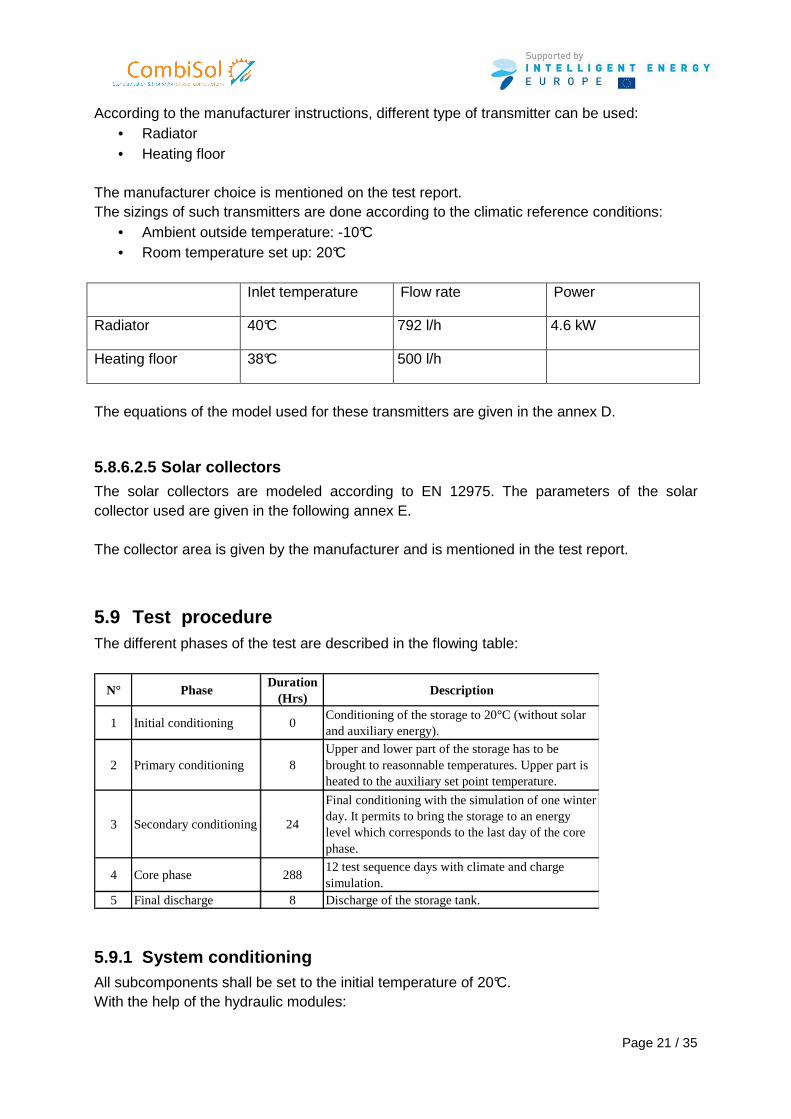
5.9 Test procedure The different phases of the test are described in the flowing table:
N° PhaseDuration
(Hrs)Description
1 Initial conditioning 0Conditioning of the storage to 20°C (without solar and auxiliary energy).
2 Primary conditioning 8Upper and lower part of the storage has to be brought to reasonnable temperatures. Upper part is heated to the auxiliary set point temperature.
3 Secondary conditioning 24
Final conditioning with the simulation of one winter day. It permits to bring the storage to an energy level which corresponds to the last day of the core phase.
4 Core phase 28812 test sequence days with climate and charge simulation.
5 Final discharge 8 Discharge of the storage tank.
5.9.1 System conditioning All subcomponents shall be set to the initial temperature of 20°C. With the help of the hydraulic modules:
Page 22 / 35
• Set the temperature to 20°C at the different inlet s of the tested system • Wait until the outlets temperature of the tested system are stabilized at 20°C.
5.9.2 Primary conditioning The upper part of the storage tank has to be set to the set temperature given by the manufacturer. It can be done by using the boiler and by forcing the circulation of the DHW loop of the boiler.
5.9.3 Secondary conditioning The secondary conditioning takes 24 hours. It corresponds to a winter day in order to heat the system and the tank before the test sequence begins. This day which is also the last day of the test sequence is included in the test sequence file.
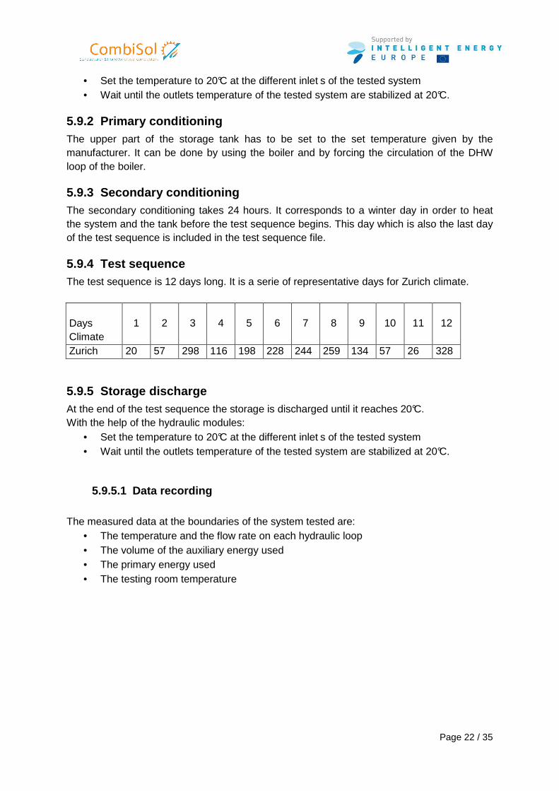
5.9.4 Test sequence The test sequence is 12 days long. It is a serie of representative days for Zurich climate. Days Climate
1 2 3 4 5 6 7 8 9 10 11 12
Zurich 20 57 298 116 198 228 244 259 134 57 26 328
5.9.5 Storage discharge At the end of the test sequence the storage is discharged until it reaches 20°C. With the help of the hydraulic modules:
• Set the temperature to 20°C at the different inlet s of the tested system • Wait until the outlets temperature of the tested system are stabilized at 20°C.
5.9.5.1 Data recording
The measured data at the boundaries of the system tested are:
• The temperature and the flow rate on each hydraulic loop • The volume of the auxiliary energy used • The primary energy used • The testing room temperature
Page 23 / 35
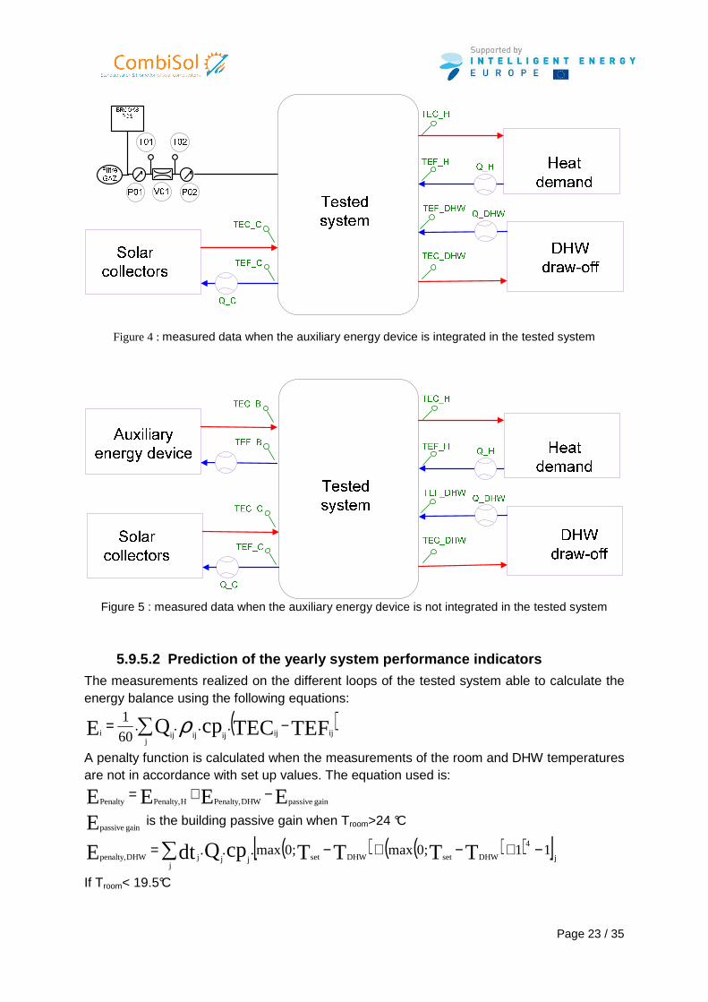
Figure 4 : measured data when the auxiliary energy device is integrated in the tested system
Figure 5 : measured data when the auxiliary energy device is not integrated in the tested system
5.9.5.2 Prediction of the yearly system performance indicators
The measurements realized on the different loops of the tested system able to calculate the energy balance using the following equations:
( )TEFTECcpQE ijijijijj
iji....
60
1 −= ∑ ρ
A penalty function is calculated when the measurements of the room and DHW temperatures are not in accordance with set up values. The equation used is:
EEEE gain passiveDHWPenalty,HPenalty,Penalty−+=
E gain passive is the building passive gain when Troom>24 °C
( ) ( )( )[ ]j
4
DHWsetDHWsetjj
jjDHWpenalty,110;max0;max... TTTTcpQdtE −+−+−=∑
If Troom< 19.5°C
Page 24 / 35
( ) ( ) ( )( )[ ]jj
2roomroomjbuildingHpenalty,
11T0;19.5maxT0;19.5max0;.maxdt.UAE ∑ −+−+−=
C24TroomC 19.5 If °≤≤°
0E Hpenalty,=
Si Troom> 24°C
( ) ( ) ( )( )[ ]jj
2roomroomjbuildingHpenalty,
1124T0;max24T0;max0;.maxdt.UAE ∑ −+−+−=
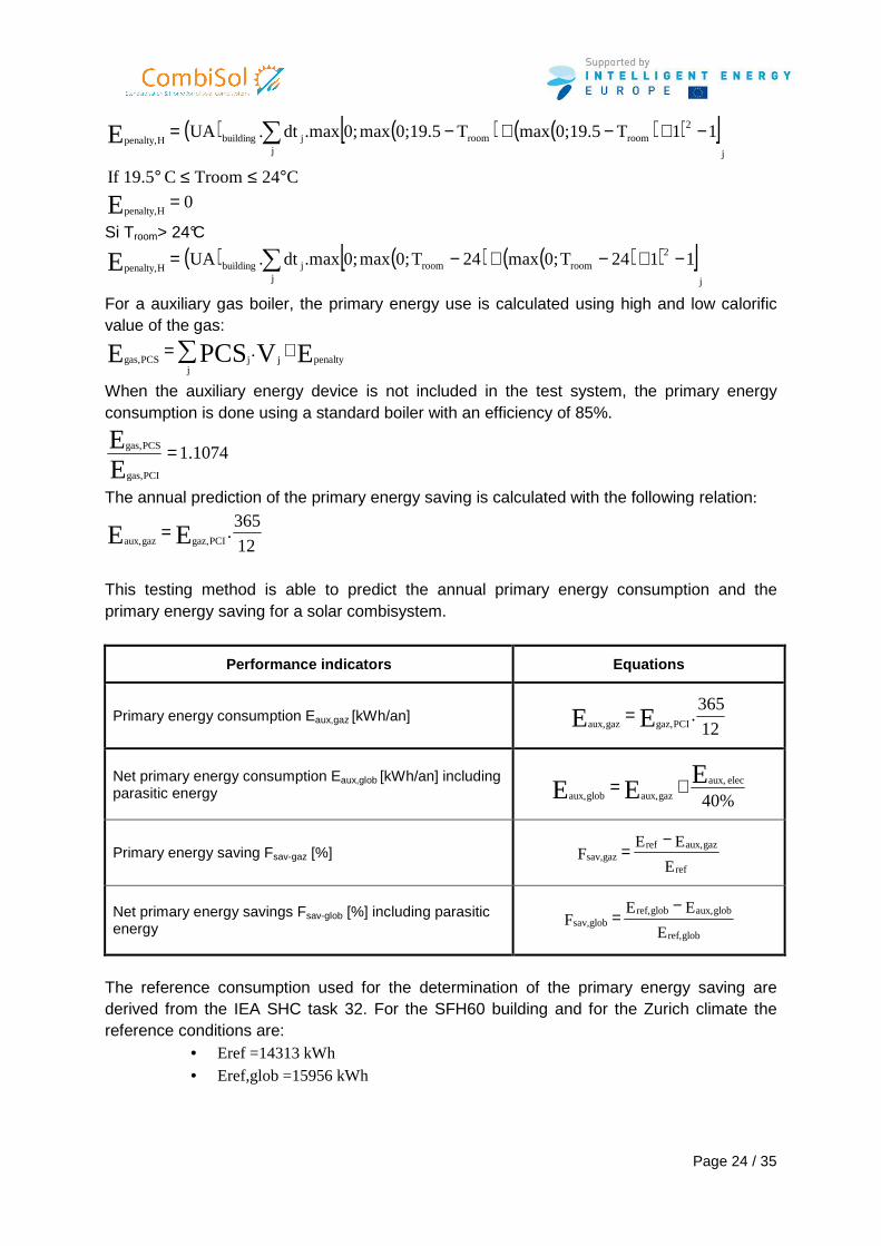
For a auxiliary gas boiler, the primary energy use is calculated using high and low calorific value of the gas:
EVPCSE penaltyj
jjPCSgas,. +=∑
When the auxiliary energy device is not included in the test system, the primary energy consumption is done using a standard boiler with an efficiency of 85%.
1.1074EE
PCIgas,
PCSgas, =
The annual prediction of the primary energy saving is calculated with the following relation:
12
365.EE PCIgaz,gazaux,
=
This testing method is able to predict the annual primary energy consumption and the primary energy saving for a solar combisystem.
Performance indicators Equations
Primary energy consumption Eaux,gaz [kWh/an] 12
365.EE PCIgaz,gazaux,
=
Net primary energy consumption Eaux,glob [kWh/an] including parasitic energy %40
EEE
elec aux,
gazaux,globaux,+=
Primary energy saving Fsav-gaz [%] E
EEF
ref
gazaux,refgazsav,
−=
Net primary energy savings Fsav-glob [%] including parasitic energy E
EEF
globref,
globaux,globref,globsav,
−=
The reference consumption used for the determination of the primary energy saving are derived from the IEA SHC task 32. For the SFH60 building and for the Zurich climate the reference conditions are:
• Eref =14313 kWh • Eref,glob =15956 kWh
Page 25 / 35
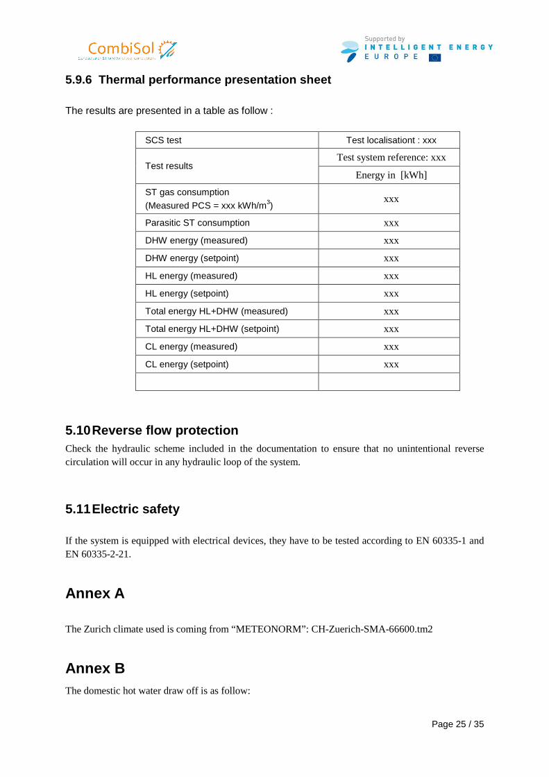
5.9.6 Thermal performance presentation sheet The results are presented in a table as follow :
SCS test Test localisationt : xxx
Test system reference: xxx Test results
Energy in [kWh]
ST gas consumption
(Measured PCS = xxx kWh/m3) xxx
Parasitic ST consumption xxx
DHW energy (measured) xxx
DHW energy (setpoint) xxx
HL energy (measured) xxx
HL energy (setpoint) xxx
Total energy HL+DHW (measured) xxx
Total energy HL+DHW (setpoint) xxx
CL energy (measured) xxx
CL energy (setpoint) xxx
5.10 Reverse flow protection Check the hydraulic scheme included in the documentation to ensure that no unintentional reverse circulation will occur in any hydraulic loop of the system.
5.11 Electric safety If the system is equipped with electrical devices, they have to be tested according to EN 60335-1 and EN 60335-2-21.
Annex A The Zurich climate used is coming from “METEONORM”: CH-Zuerich-SMA-66600.tm2
Annex B The domestic hot water draw off is as follow:
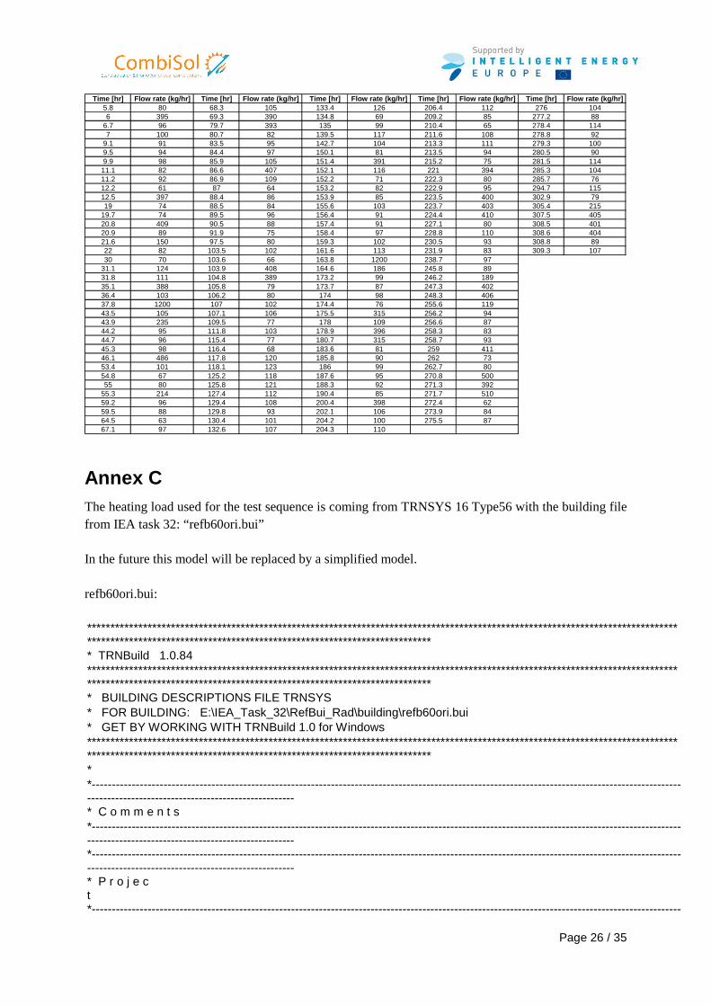
Page 26 / 35
Time [hr] Flow rate (kg/hr] Time [hr] Flow rate (kg/hr] Time [hr] Flow rate (kg/hr] Time [hr] Flow rate (kg/hr] Time [hr] Flow rate (kg/hr]5.8 80 68.3 105 133.4 126 206.4 112 276 1046 395 69.3 390 134.8 69 209.2 85 277.2 88
6.7 96 79.7 393 135 99 210.4 65 278.4 1147 100 80.7 82 139.5 117 211.6 108 278.8 92
9.1 91 83.5 95 142.7 104 213.3 111 279.3 1009.5 94 84.4 97 150.1 81 213.5 94 280.5 909.9 98 85.9 105 151.4 391 215.2 75 281.5 114
11.1 82 86.6 407 152.1 116 221 394 285.3 10411.2 92 86.9 109 152.2 71 222.3 80 285.7 7612.2 61 87 64 153.2 82 222.9 95 294.7 11512.5 397 88.4 86 153.9 85 223.5 400 302.9 7919 74 88.5 84 155.6 103 223.7 403 305.4 215
19.7 74 89.5 96 156.4 91 224.4 410 307.5 40520.8 409 90.5 88 157.4 91 227.1 80 308.5 40120.9 89 91.9 75 158.4 97 228.8 110 308.6 40421.6 150 97.5 80 159.3 102 230.5 93 308.8 8922 82 103.5 102 161.6 113 231.9 83 309.3 10730 70 103.6 66 163.8 1200 238.7 97
31.1 124 103.9 408 164.6 186 245.8 8931.8 111 104.8 389 173.2 99 246.2 18935.1 388 105.8 79 173.7 87 247.3 40236.4 103 106.2 80 174 98 248.3 40637.8 1200 107 102 174.4 76 255.6 11943.5 105 107.1 106 175.5 315 256.2 9443.9 235 109.5 77 178 109 256.6 8744.2 95 111.8 103 178.9 396 258.3 8344.7 96 115.4 77 180.7 315 258.7 9345.3 98 116.4 68 183.6 81 259 41146.1 486 117.8 120 185.8 90 262 7353.4 101 118.1 123 186 99 262.7 8054.8 67 125.2 118 187.6 95 270.8 50055 80 125.8 121 188.3 92 271.3 392
55.3 214 127.4 112 190.4 85 271.7 51059.2 96 129.4 108 200.4 398 272.4 6259.5 88 129.8 93 202.1 106 273.9 8464.5 63 130.4 101 204.2 100 275.5 8767.1 97 132.6 107 204.3 110
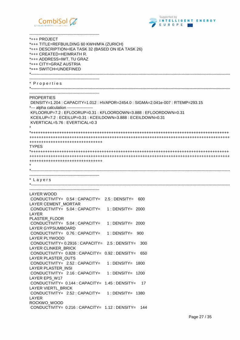
Annex C The heating load used for the test sequence is coming from TRNSYS 16 Type56 with the building file from IEA task 32: “refb60ori.bui” In the future this model will be replaced by a simplified model. refb60ori.bui: ********************************************************************************************************************************************************************************************************* * TRNBuild 1.0.84 ********************************************************************************************************************************************************************************************************* * BUILDING DESCRIPTIONS FILE TRNSYS * FOR BUILDING: E:\IEA_Task_32\RefBui_Rad\building\refb60ori.bui * GET BY WORKING WITH TRNBuild 1.0 for Windows ********************************************************************************************************************************************************************************************************* * *-------------------------------------------------------------------------------------------------------------------------------------------------------------------------------------------------------- * C o m m e n t s *-------------------------------------------------------------------------------------------------------------------------------------------------------------------------------------------------------- *-------------------------------------------------------------------------------------------------------------------------------------------------------------------------------------------------------- * P r o j e c t
*----------------------------------------------------------------------------------------------------------------------------------------------------
Page 27 / 35
---------------------------------------------------- *+++ PROJECT *+++ TITLE=REFBUILDING 60 KWH/M²A (ZURICH) *+++ DESCRIPTION=IEA TASK 32 (BASED ON IEA TASK 26) *+++ CREATED=HEIMRATH R. *+++ ADDRESS=IWT, TU GRAZ *+++ CITY=GRAZ AUSTRIA *+++ SWITCH=UNDEFINED *-------------------------------------------------------------------------------------------------------------------------------------------------------------------------------------------------------- * P r o p e r t i e s *-------------------------------------------------------------------------------------------------------------------------------------------------------------------------------------------------------- PROPERTIES DENSITY=1.204 : CAPACITY=1.012 : HVAPOR=2454.0 : SIGMA=2.041e-007 : RTEMP=293.15 *--- alpha calculation ------------------- KFLOORUP=7.2 : EFLOORUP=0.31 : KFLOORDOWN=3.888 : EFLOORDOWN=0.31 KCEILUP=7.2 : ECEILUP=0.31 : KCEILDOWN=3.888 : ECEILDOWN=0.31 KVERTICAL=5.76 : EVERTICAL=0.3 * *++++++++++++++++++++++++++++++++++++++++++++++++++++++++++++++++++++++++++++++++++++++++++++++++++++++++++++++++++++++++++++++++++++++++++++++++++++++++++++++++++++++++++++++++++++++++++++++++++++++++ TYPES *++++++++++++++++++++++++++++++++++++++++++++++++++++++++++++++++++++++++++++++++++++++++++++++++++++++++++++++++++++++++++++++++++++++++++++++++++++++++++++++++++++++++++++++++++++++++++++++++++++++++ * *-------------------------------------------------------------------------------------------------------------------------------------------------------------------------------------------------------- * L a y e r s *-------------------------------------------------------------------------------------------------------------------------------------------------------------------------------------------------------- LAYER WOOD CONDUCTIVITY= 0.54 : CAPACITY= 2.5 : DENSITY= 600 LAYER CEMENT_MORTAR CONDUCTIVITY= 5.04 : CAPACITY= 1 : DENSITY= 2000 LAYER PLASTER_FLOOR
CONDUCTIVITY= 5.04 : CAPACITY= 1 : DENSITY= 2000 LAYER GYPSUMBOARD CONDUCTIVITY= 0.76 : CAPACITY= 1 : DENSITY= 900 LAYER PLYWOOD CONDUCTIVITY= 0.2916 : CAPACITY= 2.5 : DENSITY= 300 LAYER CLINKER_BRICK CONDUCTIVITY= 0.828 : CAPACITY= 0.92 : DENSITY= 650 LAYER PLASTER_OUTS CONDUCTIVITY= 2.52 : CAPACITY= 1 : DENSITY= 1800 LAYER PLASTER_INSI CONDUCTIVITY= 2.16 : CAPACITY= 1 : DENSITY= 1200 LAYER EPS_W17 CONDUCTIVITY= 0.144 : CAPACITY= 1.45 : DENSITY= 17 LAYER VIERTL_BRICK CONDUCTIVITY= 2.52 : CAPACITY= 1 : DENSITY= 1380 LAYER ROCKWO_WOOD
CONDUCTIVITY= 0.216 : CAPACITY= 1.12 : DENSITY= 144
Page 28 / 35
LAYER CONCRETE CONDUCTIVITY= 4.788 : CAPACITY= 1.08 : DENSITY= 2000 LAYER XPS_R CONDUCTIVITY= 0.1332 : CAPACITY= 1.45 : DENSITY= 38 *-------------------------------------------------------------------------------------------------------------------------------------------------------------------------------------------------------- * I n p u t s *-------------------------------------------------------------------------------------------------------------------------------------------------------------------------------------------------------- INPUTS RADHEAT CONHEAT N_PERSON I_GAIN S_BUILDING I_AIRCH T_COOL N_AIRCHRATE T_HRS CLO_VAL T_ROOM_SET *-------------------------------------------------------------------------------------------------------------------------------------------------------------------------------------------------------- * S c h e d u l e s *-------------------------------------------------------------------------------------------------------------------------------------------------------------------------------------------------------- *-------------------------------------------------------------------------------------------------------------------------------------------------------------------------------------------------------- * W a l l s *-------------------------------------------------------------------------------------------------------------------------------------------------------------------------------------------------------- WALL C_GROU_FL LAYERS = WOOD PLASTER_FLOOR XPS_R CONCRETE THICKNESS= 0.015 0.06 0.12 0.2 ABS-FRONT= 0.4 : ABS-BACK= 0 HFRONT = 11 : HBACK= 0 WALL B_ROOF_LI LAYERS = GYPSUMBOARD PLYWOOD ROCKWO_WOOD PLYWOOD THICKNESS= 0.02 0.015 0.18 0.015 ABS-FRONT= 0.4 : ABS-BACK= 0.6 HFRONT = 11 : HBACK= 64 WALL A_EXT_WA LAYERS = PLASTER_INSI VIERTL_BRICK EPS_W17 PLASTER_OUTS THICKNESS= 0.015 0.21 0.12 0.03 ABS-FRONT= 0.4 : ABS-BACK= 0.6 HFRONT = 11 : HBACK= 64 WALL I_INN_WA LAYERS = CLINKER_BRICK THICKNESS= 0.2 ABS-FRONT= 0.4 : ABS-BACK= 0.4 HFRONT = 11 : HBACK= 11 *-------------------------------------------------------------------------------------------------------------------------------------------------------------------------------------------------------- * W i n d o w s *-------------------------------------------------------------------------------------------------------------------------------------------------------------------------------------------------------- WINDOW WSV_AR WINID=2004 : HINSIDE=11 : HOUTSIDE=64 : SLOPE=90 : SPACID=0 : WWID=0 : WHEIG=0 : FFRAME=0.15 : UFRAME=8.17 : ABSFRAME=0.6 : RISHADE=0 : RESHADE=0 : REFLISHADE=0 : REFLOSHADE=0.5 : CCISHADE=0.3 *-------------------------------------------------------------------------------------------------------------------------------------------------------------------------------------------------------- * D e f a u l t G a i n s *-------------------------------------------------------------------------------------------------------------------------------------------------------------------------------------------------------- GAIN PERS_ISO01 CONVECTIVE=144 : RADIATIVE=72 : HUMIDITY=0.059
Page 29 / 35
*-------------------------------------------------------------------------------------------------------------------------------------------------------------------------------------------------------- * O t h e r G a i n s *-------------------------------------------------------------------------------------------------------------------------------------------------------------------------------------------------------- GAIN HAUS2
CONVECTIVE=INPUT 3.6*I_GAIN : RADIATIVE=0 : HUMIDITY=0 GAIN RADHEAT CONVECTIVE=0 : RADIATIVE=INPUT 1*RADHEAT : HUMIDITY=0 GAIN CONHEAT CONVECTIVE=INPUT 1*CONHEAT : RADIATIVE=0 : HUMIDITY=0 *-------------------------------------------------------------------------------------------------------------------------------------------------------------------------------------------------------- * C o m f o r t *-------------------------------------------------------------------------------------------------------------------------------------------------------------------------------------------------------- COMFORT COMF_T32 CLOTHING=INPUT 1*CLO_VAL : MET=1.2 : WORK=0 : VELOCITY=0.1 *-------------------------------------------------------------------------------------------------------------------------------------------------------------------------------------------------------- * I n f i l t r a t i o n *-------------------------------------------------------------------------------------------------------------------------------------------------------------------------------------------------------- INFILTRATION INF_T32 AIRCHANGE=INPUT 1.6*I_AIRCH+0.4 INFILTRATION INF_T32_FREE AIRCHANGE=INPUT 1*N_AIRCHRATE+0.4 *-------------------------------------------------------------------------------------------------------------------------------------------------------------------------------------------------------- * V e n t i l a t i o n *-------------------------------------------------------------------------------------------------------------------------------------------------------------------------------------------------------- VENTILATION VENT_T32 TEMPERATURE=INPUT 1*T_HRS AIRCHANGE=INPUT 1*N_AIRCHRATE HUMIDITY=OUTSIDE *-------------------------------------------------------------------------------------------------------------------------------------------------------------------------------------------------------- * C o o l i n g
*-------------------------------------------------------------------------------------------------------------------------------------------------------------------------------------------------------- COOLING COOL_T32 ON=INPUT 1*T_COOL POWER=0 HUMIDITY=100 *-------------------------------------------------------------------------------------------------------------------------------------------------------------------------------------------------------- * H e a t i n g *-------------------------------------------------------------------------------------------------------------------------------------------------------------------------------------------------------- HEATING HEAT_20 ON=INPUT 1*T_ROOM_SET POWER=0 HUMIDITY=0
Page 30 / 35
RRAD=0 * *-------------------------------------------------------------------------------------------------------------------------------------------------------------------------------------------------------- * Z o n e s *-------------------------------------------------------------------------------------------------------------------------------------------------------------------------------------------------------- ZONES ERDGE *-------------------------------------------------------------------------------------------------------------------------------------------------------------------------------------------------------- * O r i e n t a t i o n s *-------------------------------------------------------------------------------------------------------------------------------------------------------------------------------------------------------- ORIENTATIONS NORTH SOUTH EAST WEST ROOFANG ROOFSOUTH ROOFNORTH * *++++++++++++++++++++++++++++++++++++++++++++++++++++++++++++++++++++++++++++++++++++++++++++++++++++++++++++++++++++++++++++++++++++++++++++++++++++++++++++++++++++++++++++++++++++++++++++++++++++++++ BUILDING *++++++++++++++++++++++++++++++++++++++++++++++++++++++++++++++++++++++++++++++++++++++++++++++++++++++++++++++++++++++++++++++++++++++++++++++++++++++++++++++++++++++++++++++++++++++++++++++++++++++++ * *-------------------------------------------------------------------------------------------------------------------------------------------------------------------------------------------------------- * Z o n e ERDGE / A i r n o d e ERDGE *-------------------------------------------------------------------------------------------------------------------------------------------------------------------------------------------------------- ZONE ERDGE AIRNODE ERDGE WALL =C_GROU_FL : SURF= 1 : AREA= 70 : BOUNDARY=IDENTICAL WALL =A_EXT_WA : SURF= 2 : AREA= 36.5 : EXTERNAL : ORI=EAST : FSKY=0.5 WINDOW=WSV_AR : SURF= 3 : AREA= 4 : EXTERNAL : ORI=EAST : FSKY=0.5 : ESHADE=INPUT 1*S_BUILDING WALL =A_EXT_WA : SURF= 4 : AREA= 36.5 : EXTERNAL : ORI=WEST : FSKY=0.5 WINDOW=WSV_AR : SURF= 5 : AREA= 4 : EXTERNAL : ORI=WEST : FSKY=0.5 : ESHADE=INPUT 1*S_BUILDING WALL =A_EXT_WA : SURF= 6 : AREA= 47 : EXTERNAL : ORI=NORTH : FSKY=0.5 WINDOW=WSV_AR : SURF= 7 : AREA= 3 : EXTERNAL : ORI=NORTH : FSKY=0.5 WALL =A_EXT_WA : SURF= 8 : AREA= 38 : EXTERNAL : ORI=SOUTH : FSKY=0.5 WINDOW=WSV_AR : SURF= 9 : AREA= 12 : EXTERNAL : ORI=SOUTH : FSKY=0.5 : ESHADE=INPUT 1*S_BUILDING WALL =B_ROOF_LI : SURF= 10 : AREA= 25 : EXTERNAL : ORI=ROOFSOUTH : FSKY=0.8 WALL =I_INN_WA : SURF= 11 : AREA= 200 : INTERNAL WALL =B_ROOF_LI : SURF= 12 : AREA= 61.4 : EXTERNAL : ORI=ROOFNORTH : FSKY=0.4 REGIME GAIN = PERS_ISO01 : SCALE= INPUT 1*N_PERSON GAIN = HAUS2 : SCALE= 1 GAIN = RADHEAT : SCALE= 1 GAIN = CONHEAT : SCALE= 1 COMFORT = COMF_T32 VENTILATION = VENT_T32 COOLING = COOL_T32
HEATING = HEAT_20 CAPACITANCE = 750 : VOLUME= 354 : TINITIAL= 20 : PHINITIAL= 50 : WCAPR= 1 *----------------------------------------------------------------------------------------------------------------------------------------------------
Page 31 / 35
---------------------------------------------------- * O u t p u t s *-------------------------------------------------------------------------------------------------------------------------------------------------------------------------------------------------------- OUTPUTS TRANSFER : TIMEBASE=1.000 AIRNODES = ERDGE NTYPES = 1 : TAIR - air temperature of zone AIRNODES = ERDGE NTYPES = 32 : SQHEAT - sum of sensible heating demand for group of zones (positive values) AIRNODES = ERDGE NTYPES = 38 : SQGCON - sum of internal convective gains for group of zones AIRNODES = ERDGE NTYPES = 42 : SQSOLT - sum of solar radiation transmitted through windows for group of zones (but not kept 100 % in zone) AIRNODES = ERDGE NTYPES = 23 : TSTAR - star node temperature of zone AIRNODES = ERDGE NTYPES = 43 : SGQRAD - sum of total internal radiative gains for group of zones AIRNODES = ERDGE NTYPES = 904 : BAL_4 - energy balance for a zone AIRNODES = ERDGE NTYPES = 62 : PMV - predicted mean vote (PMV) value of zone = 63 : PPD - predicted percentage of dissatisfied persons (PPD) of zone = 9 : RELHUM - relativ humidity of zone air = 33 : SQCOOL - sum of sensible cooling demand for group of zones (positive values) AIRNODES = ERDGE NTYPES = 25 : TOP - operative zone temperature *-------------------------------------------------------------------------------------------------------------------------------------------------------------------------------------------------------- * E n d *-------------------------------------------------------------------------------------------------------------------------------------------------------------------------------------------------------- END
_EXTENSION_WINPOOL_START_ WINDOW 4.1 DOE-2 Data File : Multi Band Calculation Unit System : SI Name : TRNSYS 15 WINDOW LIB Desc : Waermeschutzglas,Ar, 1.4 71/59 Window ID : 2001 Tilt : 90.0 Glazings : 2 Frame : 11 2.270 Spacer : 1 Class1 2.330 -0.010 0.138 Total Height: 1219.2 mm Total Width : 914.4 mm Glass Height: 1079.5 mm Glass Width : 774.7 mm Mullion : None Gap Thick Cond dCond Vis dVis Dens dDens Pr dPr 1 Argon 16.0 0.01620 5.000 2.110 6.300 1.780 -0.0060 0.680 0.00066 2 0 0 0 0 0 0 0 0 0 3 0 0 0 0 0 0 0 0 0 4 0 0 0 0 0 0 0 0 0 5 0 0 0 0 0 0 0 0 0
Page 32 / 35
Angle 0 10 20 30 40 50 60 70 80 90 Hemis Tsol 0.426 0.428 0.422 0.413 0.402 0.380 0.333 0.244 0.113 0.000 0.354 Abs1 0.118 0.118 0.120 0.123 0.129 0.135 0.142 0.149 0.149 0.000 0.132 Abs2 0.190 0.192 0.198 0.201 0.200 0.199 0.199 0.185 0.117 0.000 0.191 Abs3 0 0 0 0 0 0 0 0 0 0 0 Abs4 0 0 0 0 0 0 0 0 0 0 0 Abs5 0 0 0 0 0 0 0 0 0 0 0 Abs6 0 0 0 0 0 0 0 0 0 0 0 Rfsol 0.266 0.262 0.260 0.262 0.269 0.286 0.326 0.422 0.621 1.000 0.314 Rbsol 0.215 0.209 0.207 0.210 0.219 0.237 0.272 0.356 0.560 0.999 0.260 Tvis 0.706 0.710 0.701 0.688 0.670 0.635 0.556 0.403 0.188 0.000 0.590 Rfvis 0.121 0.115 0.114 0.118 0.132 0.163 0.228 0.376 0.649 1.000 0.203 Rbvis 0.103 0.096 0.093 0.096 0.108 0.132 0.179 0.286 0.520 0.999 0.162 SHGC 0.589 0.593 0.591 0.586 0.574 0.551 0.505 0.405 0.218 0.000 0.518 SC: 0.55 Layer ID# 9052 9065 0 0 0 0 Tir 0.000 0.000 0 0 0 0 Emis F 0.840 0.140 0 0 0 0 Emis B 0.840 0.840 0 0 0 0 Thickness(mm) 4.0 4.0 0 0 0 0 Cond(W/m2-C ) 225.0 225.0 0 0 0 0 Spectral File None None None None None None Overall and Center of Glass Ig U-values (W/m2-C) Outdoor Temperature -17.8 C 15.6 C 26.7 C 37.8 C Solar WdSpd hcout hrout hin (W/m2) (m/s) (W/m2-C) 0 0.00 12.25 3.25 7.62 1.54 1.54 1.31 1.31 1.35 1.35 1.47 1.47 0 6.71 25.47 3.21 7.64 1.62 1.62 1.36 1.36 1.40 1.40 1.53 1.53 783 0.00 12.25 3.39 7.99 1.69 1.69 1.54 1.54 1.51 1.51 1.54 1.54 783 6.71 25.47 3.30 7.81 1.79 1.79 1.63 1.63 1.58 1.58 1.59 1.59 WINDOW 4.1 DOE-2 Data File : Multi Band Calculation Unit System : SI Name : TRNSYS 15 WINDOW LIB Desc : Waermeschutzglas,Ar, 1.4 71/59 Window ID : 2101 Tilt : 90.0 Glazings : 2 Frame : 11 2.270 Spacer : 1 Class1 2.330 -0.010 0.138 Total Height: 1639.7 mm Total Width : 1239.3 mm Glass Height: 1500.0 mm Glass Width : 1100.0 mm Mullion : None Gap Thick Cond dCond Vis dVis Dens dDens Pr dPr 1 Argon 16.0 0.01620 5.000 2.110 6.300 1.780 -0.0060 0.680 0.00066 2 0 0 0 0 0 0 0 0 0 3 0 0 0 0 0 0 0 0 0 4 0 0 0 0 0 0 0 0 0 5 0 0 0 0 0 0 0 0 0 Angle 0 10 20 30 40 50 60 70 80 90 Hemis Tsol 0.426 0.428 0.422 0.413 0.402 0.380 0.333 0.244 0.113 0.000 0.354 Abs1 0.118 0.118 0.120 0.123 0.129 0.135 0.142 0.149 0.149 0.000 0.132 Abs2 0.190 0.192 0.198 0.201 0.200 0.199 0.199 0.185 0.117 0.000 0.191 Abs3 0 0 0 0 0 0 0 0 0 0 0 Abs4 0 0 0 0 0 0 0 0 0 0 0
Page 33 / 35
Abs5 0 0 0 0 0 0 0 0 0 0 0 Abs6 0 0 0 0 0 0 0 0 0 0 0 Rfsol 0.266 0.262 0.260 0.262 0.269 0.286 0.326 0.422 0.621 1.000 0.314 Rbsol 0.215 0.209 0.207 0.210 0.219 0.237 0.272 0.356 0.560 0.999 0.260 Tvis 0.706 0.710 0.701 0.688 0.670 0.635 0.556 0.403 0.188 0.000 0.590 Rfvis 0.121 0.115 0.114 0.118 0.132 0.163 0.228 0.376 0.649 1.000 0.203 Rbvis 0.103 0.096 0.093 0.096 0.108 0.132 0.179 0.286 0.520 0.999 0.162 SHGC 0.589 0.593 0.591 0.586 0.574 0.551 0.505 0.405 0.218 0.000 0.518 SC: 0.55 Layer ID# 9052 9065 0 0 0 0 Tir 0.000 0.000 0 0 0 0 Emis F 0.840 0.140 0 0 0 0 Emis B 0.840 0.840 0 0 0 0 Thickness(mm) 4.0 4.0 0 0 0 0 Cond(W/m2-C ) 225.0 225.0 0 0 0 0 Spectral File None None None None None None Overall and Center of Glass Ig U-values (W/m2-C) Outdoor Temperature -17.8 C 15.6 C 26.7 C 37.8 C Solar WdSpd hcout hrout hin (W/m2) (m/s) (W/m2-C) 0 0.00 12.25 3.25 7.62 1.54 1.54 1.31 1.31 1.35 1.35 1.47 1.47 0 6.71 25.47 3.21 7.64 1.62 1.62 1.36 1.36 1.40 1.40 1.53 1.53 783 0.00 12.25 3.39 7.99 1.69 1.69 1.54 1.54 1.51 1.51 1.54 1.54 783 6.71 25.47 3.30 7.81 1.79 1.79 1.63 1.63 1.58 1.58 1.59 1.59 WINDOW 4.1 DOE-2 Data File : Multi Band Calculation Unit System : SI Name : TRNSYS 15 WINDOW LIB Desc : Waermeschutzglas,Ar, 1.3 75/62 Window ID : 2005 Tilt : 90.0 Glazings : 2 Frame : 11 2.270 Spacer : 1 Class1 2.330 -0.010 0.138 Total Height: 1219.2 mm Total Width : 914.4 mm Glass Height: 1079.5 mm Glass Width : 774.7 mm Mullion : None Gap Thick Cond dCond Vis dVis Dens dDens Pr dPr 1 Argon 16.0 0.01620 5.000 2.110 6.300 1.780 -0.0060 0.680 0.00066 2 0 0 0 0 0 0 0 0 0 3 0 0 0 0 0 0 0 0 0 4 0 0 0 0 0 0 0 0 0 5 0 0 0 0 0 0 0 0 0 Angle 0 10 20 30 40 50 60 70 80 90 Hemis Tsol 0.462 0.465 0.458 0.448 0.436 0.412 0.360 0.263 0.121 0.000 0.384 Abs1 0.114 0.114 0.116 0.120 0.125 0.132 0.139 0.146 0.147 0.000 0.128 Abs2 0.186 0.188 0.195 0.199 0.198 0.197 0.199 0.186 0.118 0.000 0.189 Abs3 0 0 0 0 0 0 0 0 0 0 0 Abs4 0 0 0 0 0 0 0 0 0 0 0 Abs5 0 0 0 0 0 0 0 0 0 0 0 Abs6 0 0 0 0 0 0 0 0 0 0 0 Rfsol 0.237 0.232 0.231 0.233 0.241 0.260 0.303 0.406 0.614 1.000 0.289 Rbsol 0.179 0.172 0.170 0.173 0.183 0.202 0.239 0.328 0.542 0.999 0.227 Tvis 0.749 0.754 0.743 0.730 0.711 0.674 0.589 0.428 0.200 0.000 0.626 Rfvis 0.121 0.115 0.114 0.118 0.132 0.163 0.228 0.376 0.649 1.000 0.203
Page 34 / 35
Rbvis 0.109 0.102 0.099 0.102 0.115 0.140 0.188 0.296 0.529 0.999 0.170 SHGC 0.624 0.629 0.627 0.622 0.608 0.584 0.534 0.427 0.227 0.000 0.549 SC: 0.58 Layer ID# 9052 9055 0 0 0 0 Tir 0.000 0.000 0 0 0 0 Emis F 0.840 0.100 0 0 0 0 Emis B 0.840 0.840 0 0 0 0 Thickness(mm) 4.0 4.0 0 0 0 0 Cond(W/m2-C ) 225.0 225.0 0 0 0 0 Spectral File None None None None None None Overall and Center of Glass Ig U-values (W/m2-C) Outdoor Temperature -17.8 C 15.6 C 26.7 C 37.8 C Solar WdSpd hcout hrout hin (W/m2) (m/s) (W/m2-C) 0 0.00 12.25 3.24 7.60 1.46 1.46 1.20 1.20 1.23 1.23 1.35 1.35 0 6.71 25.47 3.21 7.63 1.53 1.53 1.23 1.23 1.27 1.27 1.40 1.40 783 0.00 12.25 3.38 8.02 1.61 1.61 1.42 1.42 1.37 1.37 1.39 1.39 783 6.71 25.47 3.29 7.86 1.70 1.70 1.50 1.50 1.44 1.44 1.43 1.43 WINDOW 4.1 DOE-2 Data File : Multi Band Calculation Unit System : SI Name : TRNSYS 15 WINDOW LIB Desc : Waermeschutzglas,Ar, 1.4 74/62 Window ID : 2004 Tilt : 90.0 Glazings : 2 Frame : 11 2.270 Spacer : 1 Class1 2.330 -0.010 0.138 Total Height: 1219.2 mm Total Width : 914.4 mm Glass Height: 1079.5 mm Glass Width : 774.7 mm Mullion : None Gap Thick Cond dCond Vis dVis Dens dDens Pr dPr 1 Argon 16.0 0.01620 5.000 2.110 6.300 1.780 -0.0060 0.680 0.00066 2 0 0 0 0 0 0 0 0 0 3 0 0 0 0 0 0 0 0 0 4 0 0 0 0 0 0 0 0 0 5 0 0 0 0 0 0 0 0 0 Angle 0 10 20 30 40 50 60 70 80 90 Hemis Tsol 0.462 0.465 0.458 0.448 0.436 0.412 0.360 0.263 0.121 0.000 0.384 Abs1 0.114 0.114 0.116 0.120 0.125 0.132 0.139 0.146 0.147 0.000 0.128 Abs2 0.186 0.188 0.195 0.199 0.198 0.197 0.199 0.186 0.118 0.000 0.189 Abs3 0 0 0 0 0 0 0 0 0 0 0 Abs4 0 0 0 0 0 0 0 0 0 0 0 Abs5 0 0 0 0 0 0 0 0 0 0 0 Abs6 0 0 0 0 0 0 0 0 0 0 0 Rfsol 0.237 0.232 0.231 0.233 0.241 0.260 0.303 0.406 0.614 1.000 0.289 Rbsol 0.179 0.172 0.170 0.173 0.183 0.202 0.239 0.328 0.542 0.999 0.227 Tvis 0.749 0.754 0.743 0.730 0.711 0.674 0.589 0.428 0.200 0.000 0.626 Rfvis 0.121 0.115 0.114 0.118 0.132 0.163 0.228 0.376 0.649 1.000 0.203 Rbvis 0.109 0.102 0.099 0.102 0.115 0.140 0.188 0.296 0.529 0.999 0.170 SHGC 0.622 0.626 0.625 0.619 0.606 0.581 0.532 0.424 0.226 0.000 0.546 SC: 0.58 Layer ID# 9052 9054 0 0 0 0 Tir 0.000 0.000 0 0 0 0 Emis F 0.840 0.140 0 0 0 0
Page 35 / 35
Emis B 0.840 0.840 0 0 0 0 Thickness(mm) 4.0 4.0 0 0 0 0 Cond(W/m2-C ) 225.0 225.0 0 0 0 0 Spectral File None None None None None None Overall and Center of Glass Ig U-values (W/m2-C) Outdoor Temperature -17.8 C 15.6 C 26.7 C 37.8 C Solar WdSpd hcout hrout hin (W/m2) (m/s) (W/m2-C) 0 0.00 12.25 3.25 7.62 1.54 1.54 1.31 1.31 1.35 1.35 1.47 1.47 0 6.71 25.47 3.21 7.64 1.62 1.62 1.36 1.36 1.40 1.40 1.53 1.53 783 0.00 12.25 3.39 7.96 1.69 1.69 1.54 1.54 1.51 1.51 1.54 1.54 783 6.71 25.47 3.30 7.78 1.79 1.79 1.63 1.63 1.57 1.57 1.59 1.59 *** END OF LIBRARY *** *************************************************************************************************** *WinID Description Design U-Value g-value T-sol Rf-sol T-vis *************************************************************************************************** 2001 Waermeschutzglas,Ar, 1.4 71/59 4/16/4 1.4 0.589 0.426 0.266 0.706 2101 Waermeschutzglas,Ar, 1.4 71/59 4/16/4 1.4 0.589 0.426 0.266 0.706 2005 Waermeschutzglas,Ar, 1.3 75/62 4/16/4 1.27 0.624 0.462 0.237 0.749 2004 Waermeschutzglas,Ar, 1.4 74/62 4/16/4 1.4 0.622 0.462 0.237 0.749 _EXTENSION_WINPOOL_END_
Annex D
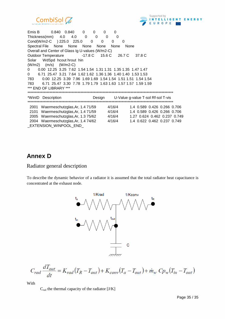
Radiator general description To describe the dynamic behavior of a radiator it is assumed that the total radiator heat capacitance is concentrated at the exhaust node.
With Crad the thermal capacity of the radiator [J/K]
Page 36 / 35
Tin inlet fluid temperature of the radiator [K] Tout outlet fluid temperature of the radiator [K] TR: resulting temperature [K] Ta: air temperature [K] Kconv: convective heat transfer coefficient of the radiator [W/K] Krad radiatif heat transfer coefficient of the radiator [W/K]
Heating floor general description Contribution à l'amélioration de la technique du Plancher Solaire Direct : Analyse de la solution "dalles mince" et gestion optimisée du chauffage d'appoint - Thèse : Université de Savoie, 1992, 337 p.
Annex E See EN12975 “A solar collector model for TRNSYS simulation and system testing”, report of IEA task 26 (2002)