Embed Size (px)
Citation preview

Available online at www.sciencedirect.com
Physics Procedia 12 (2011) 215–223
1875-3892 © 2011 Published by Elsevier Ltd.doi:10.1016/j.phpro.2011.03.028
LiM 2011
Combined Laser Beam Welding and Brazing Process for Aluminium Titanium Hybrid Structures
F. Möller*, M. Grden, C. Thomy, F. Vollertsen
BIAS – Bremer Institut für angewandte Strahltechnik GmbH, Klagenfurter Str. 2, 28359 Bremen, Germany
Abstract
The current state of the art in light-weight construction is – for the case of aircraft structures – the use of either aluminium or titanium. Whereas aluminium is light-weight and less expensive, titanium offers superior corrosion properties at higher cost. In order to combine the advantages of both materials, a hybrid Ti-Al structure is proposed for e.g. seat-track application. In this paper, an overview of the results from this research work and the accompanying thermo-mechanical simulations will be reported and discussed. On the basis of the development of an appropriate system technology, the process development will be described, focusing on the main influencing parameters of the process on joint properties.
Keywords: laser; joining; aluminium; titanium
1. Motivation
Due to the demand for light-weight constructions to reduce fuel consumption especially in the aerospace and automotive industries, aluminium is widely used [1]. Nowadays, in conventional wide-bodied aircrafts, aluminium is used for seat tracks. To avoid corrosion from the presence of liquids in the passenger cabin, it is desired to utilize titanium instead of aluminium in the imperilled area of the seat track, the so-called crown, to which seats and other elements of the cabin are mounted. Since the remaining seat track part should still be made of aluminium, a joining technology for aluminium-titanium butt joints needs to be developed [2].
Currently, the connection of structural elements from dissimilar materials like aluminum (e.g. EN AW-6056) and titanium (e.g. TiAl6V4) can be realized e.g. by mechanical joining processes such as riveting [3]. The key aspect during thermal joining of aluminum to titanium is the formation of intermetallic phases [4], which depends on process-related temperature-time cycles [5]. As a result of excessive phase formation, embrittlement of the joining zone is observed [6]. Thus, if joints with high toughness and strength are required, the intermetallic phase layer has to be limited to a minimum thickness [7].
Aside from such welding processes as diffusion welding, which are certainly not appropriate for joining aluminium - titanium specimens in a length of 6 m or more, some research concerning local joining processes for titanium to aluminum has been published. Nippon Aluminum suggested taking titanium clad with copper in combination with a zinc aluminum soldering metal; the joint should be made by ultra sonic welding [8]. Other
*Corresponding author. Tel.: +49-421-218-5035; Fax: +49-421-218-5063. E-mail address: [email protected].
Open access under CC BY-NC-ND license.

216 F. Möller et al. / Physics Procedia 12 (2011) 215–223
techniques have been presented by Suoda [9] and Fuji [10]. Suoda reported on aluminum-titanium joining using an electron beam. Fuji used a friction welding process for this kind of dissimilar joint.
Among the local processes, laser-based processes so far have demonstrated the most promising results for joining of aluminium - titanium hybrid structures [11]. Therefore, a laser-based joining process for titanium-aluminium seat-tracks was developed and investigated both in experiment and FEM simulation, the results of which are presented and discussed in this paper.
Considering local, laser-based processes [12], some research was also done at the institute of the authors [13]. In figure 1 a suitable process for aluminium titanium process is shown.
Aluminium
Titanium
Laserbeam
wire
a) b)Laser beam
titanium
aluminium
Figure 1. Principle of laser welding of aluminium and titanium for overlap (a) and butt joint (b) geometry [15]
For the overlap configuration the laser spot was de-focussed and directed onto the titanium sheet. Heating up the titanium, the aluminium alloy was molten by the heat transferred from the titanium sheet. After this, the un-molten titanium sheet was pressed onto the aluminium using a pressure roller head to realize a metallic joint by the effect of diffusion.
For the aluminium titanium butt joint configuration, the focus spot of the laser beam was on the surface of the specimens. The exact positioning of the spot was necessary to realize a reproducible welding result. In this process, the focus was displaced on the titanium. To minimize the formation of a gap between both joining partners, the specimens were fixed in a special clamping device. The failure of this joint in tensile testing was on the aluminium side.
In summary, Titanium materials offer excellent mechanical properties and corrosion resistance combined with low specific weight [14]. This qualifies titanium for lightweight applications in aviation, automotive and energy engineering [15]. Furthermore, a laser beam process can be used for local joining of aluminium titanium hybrid structures. To transfer laser-based processes for this task into industry, the joining equipment has to be enhanced. Therefore, sensors have to be adapted to guarantee a constant and exact positioning of the laser spot and specimens to achieve reproducible joint appearances and properties.
2. Methods
2.1 Experimental
Figure 2 shows the principle of the developed simultaneous double-sided joining process. Prior to the experiments, the aluminum side of the joint area was machined by milling of a material reservoir shape into the sheet metal, which acts as filler material. The sheets are arranged in vertical position with aluminum on top to achieve a good wetting of the titanium sheet under the effect of gravity.

F. Möller et al. / Physics Procedia 12 (2011) 215–223 217
Prior to processing After welding
Aluminium
Titanium
Aluminium
Titanium
Figure 2. Process principle of the aluminum-titanium joining process As sketched in figure 2, the laser beams are not working in focus with a laser power of 1.75 kW and irradiate
both aluminum and titanium. Thus, a heat conduction weld with a welding speed of 0.22 m/min is produced, melting the aluminum and heating up the titanium to ensure a wetting by the aluminum melt. The titanium remains in a solid state during joining; the joint is achieved by the formation of intermetallic phases between both materials, which however need to be kept small due to their high brittleness. The basic investigations were performed on the material combination EN AW-6056 T6/ TiAl6V4. All welded sheets were analyzed by metallographic and mechanical testing.
For the transfer of the process principle into an experimental facility, a gantry system was developed. The defocused Trumpf HL 4006D lamp pumped Nd: YAG laser has a maximum power of 4 kW. The joint was shielded by argon to reduce effects from environmental air, resulting in the potential formation of oxides and nitrides on the materials. The gantry system with the main components is shown in figure 3.
Figure 3. Joining system
For clamping, a roller head is attached onto the gantry system and is moved along the seat track during the welding process. The part of the roller head in front of the welding process consists of a pair of guide rollers and a pressure roller. The part succeeding the welding process consists of two lateral pairs of guide rollers and two
X
w
welding head
Al-Ti-specimen
entry guide rail
joining direction
welding head
roller head

218 F. Möller et al. / Physics Procedia 12 (2011) 215–223
pressure rollers, each with lower clamping force than the leading ones. To provide a steady transfer of the guide rollers and the pressure rollers, an entry and a run-out guide rail are integrated.
Special attention was paid to a reproducible positioning of the working heads with respect to the aluminium edge in order to ensure a regular wetting and a tensile strength within specifications. Therefore, laser triangulation sensors by Falldorf GmbH were mounted directly to the working heads. These sensors can detect the vertical position of the lowest aluminium edge. In figure 4 the discrepancy between the measured value of the sensor and the adjusted offset of the working heads to optimal position is shown.
-1 ,0 -0,5 0 ,0 0 ,5 [m m ] 1,04,5
5,0
5,5
6,0
6,5
[m m ]
7,0m
essu
red
me
an Y
-val
ue [m
m]
con figured re la tive d isp lacem en t in Y-d irection [m m ]Adjustedoffsetof theworkingheads
Measuredpo
sitio
nby
thesensor
Figure 4. Measured position versus adjusted offset of the working heads
It can be seen that a linear correlation between the offset and the measured position was obtained. This means that the sensor is able to identify the position of the laser spot with respect to the lowest edge of the aluminium with an accuracy of 30 µm. Thus, if the profile is measured in the clamped condition, the relative position of the welding heads can be adjusted accordingly, allowing to perform a reproducible joining process with regular wetting.
Furthermore the sensors can be used for detecting the distortion of the specimens in different positions. In the experiments the distortion in height direction was detected. For validation of the sensor data, the complete specimens were continuously measured by a coordinate measuring machine (cmm). Therefore, measurement lines were detected along the specimens in the same range as the sensor measurement area. The sensor data was filtered by calculating the arithmetic mean of 25 measurement points which equates 1.125 mm of the specimen.
3.2 Modeling
To support process development and to improve the understanding of distortion and residual stresses in such hybrid joints, a numerical model has been implemented and simulated using the finite element method. The implemented structural model consisted of nearly 40.000 finite elements, which were efficiently arranged in their dimensions with respect to local zones of critical behavior. The boundary conditions made for the thermo-mechanical simulation included standard assumptions according to the state of the art. These are exemplarily: Energy losses due to slow air convection (25 W/m2*K) and radiation (Boltzmann law), thermal energy as well as pressure transfer over sliding contact. More case - specific assumptions made are named in the following:
• Symmetric behaviour with respect to the longitudinal specimen dimension has been assumed (faster calculation times).
• Heat affected material properties of the aluminium component part have been included in several sections arranged with respect to their perpendicular distance to the joining path.
• Pressures of the three top clamping rollers were assumed to be local distributed loads.
• No melt flow has been modelled, the geometry after welding was assumed right from the start.

F. Möller et al. / Physics Procedia 12 (2011) 215–223 219
• Material properties for temperatures higher than melt temperature were partly estimated by comparison to experimental experiences.
The connection between aluminium and titanium was established by defining time and position - dependent constraints on the degrees of freedom of corresponding nodes.
3. Results and Discussion
3.1 General observation
The joint appearance follows the typical characteristics of hybrid material joints. The aluminium was molten and wetted the titanium. In figure 5, a typical joint appearance and a cross section are given. The specimen was welded with 1.75 kW laser power and 0.22 m/min welding speed. By the simultaneous welding process, a reproducible, constant wetting length of 3.6 mm and a seam reinforcement of 0.6 mm can be achieved. This results in an adequate tensile strength of approximately 300 MPa.
5 mmTi
Al
Ti2 mm
Figure 5. Joint appearance and cross section The surface of the aluminium weld shows fine weld ripples and significantly exceeds the normal weld quality for
laser welding of aluminium. Especially, there are no joint defects like pores or hot cracks detectable. The cross section shows a symmetric joint appearance. The wetting lengths on both sides are at the same value, which indicates a stable process. Because of the symmetric wetting, the specimens show reproducible joint properties and potentially less distortion than for non-symmetric wetting. The joint was realized by the formation of a phase seam, which was typically less than 2 μm thick.
On this basis, by a systematic variation of process parameters in experiment, it was demonstrated that titanium-aluminium joints with a length of 1 m with optimized properties with respect to seam appearance, seam geometry, microstructural integrity and static strength can be produced within a comparatively wide parameter envelope. With respect to geometrical parameters, it was shown that the position of the lowest edge of the aluminium profiles relative to the laser spot has a significant effect on wetting length and the resulting tensile strength.
3.2 Distortion Measurement
Due to the measurement of the specimens with the sensors and the cmm, the feasibility of the sensors for measuring the distortion can be demonstrated. With respect to the aluminium a maximum deviation of approximately 4 % between the sensor and the cmm data can be observed. Compared to the titanium specimen the measurement data of the cmm deviates 7 % from the sensor data. Therefore the sensors can be taken to measure the deformation without using the cmm.
In figure 6 the distortion of the aluminium and the titanium profile in y-direction after welding is illustrated. For an evaluation and comparison of the specimen distortion the maximum of the value is calculated.

220 F. Möller et al. / Physics Procedia 12 (2011) 215–223
z [mm]
0,5
0
-0,5
-10 100 200 300
Hei
ght-
dire
ctio
n [m
m]
z [mm]
Hei
ght -
dire
ctio
n[m
m]
0,5
0
-0,5
-10 100 200 300
z [mm]
Hei
ght -
dire
ctio
n[m
m]
0,5
0
-0,5
-10 100 200 300
Figure 6. Distortion in w – direction a) for aluminium b) for titanium
For this specimen the distortion rises to a value of approximately -0.85 mm in respect to the aluminium and -0.48 for the titanium profile. Moreover, with respect to the simulation results a distortion after welding of the specimen rises to -1.00 for the aluminium and -0.64 for the titanium profile.
Furthermore, the geometry of the profiles was measured prior welding. It was found that the titanium profile shows a significant deformation before welding to its preparation by milling. In figure 7 the deformation of a titanium profile prior welding is given.
Figure 7. Deformation of the titanium profile prior to welding
Prior to welding, a maximum deformation of this profile of approximately 0.40 mm could be identified. Based on this results it can be found out that the deformation prior welding correlates with the deformation after welding. This phenomenon is demonstrated in figure 8.

F. Möller et al. / Physics Procedia 12 (2011) 215–223 221
*o
TitaniumAluminium
Deformation of the titanium profiles prior welding[mm]
Def
orm
atio
n in
y -
dire
ctio
n af
ter
wel
ding
[mm
]
0
-0,4
-0,8
0 1 2 3Deformation of the t itanium profiles prior to
welding [mm]
Def
orm
atio
n in
w –
dire
ctio
n af
ter
wel
ding
[mm
]
titaniumaluminium
Figure 8. Deformation of the titanium profile prior to welding versus welded specimens
It can be seen that by increasing the deformation of the titanium profile prior the welding, the deformation after welding is decreasing. Based on this effect a deformation of the titanium specimens with approximately 3.49 mm prior to welding will be resulting after welding in a deformation of approximately 0 mm with respect to the aluminium profile.
3.3 Finite element simulation results
The joining process development has been supported by (initially validated) finite element simulations, which provided for one thing a detailed description of the time-temperature cycle at any desired position (figure 9). Moreover, they provided an overview on the mechanical stress and distortion behavior during and after welding (figure 10). The simulated final distortion has shown itself as very similar to the experimental results. The deviation between these two was in the range of 10 – 20 % considering the earlier addressed w-distortion (which is vertical to welding direction). The simulation results contributed to the reduction of experiments, e.g. in finding of optimized process parameters. For example, the process parameters for simplified sheet model geometry could be transferred to the seat track by increasing the laser power to 110 %.
Figure 9. Exemplary simulation result showing a snapshot of the in-process present temperature field.
A main reason for the formation of the w-distortion due to the joining process has been identified by the analysis of the thermo-mechanical simulation data. According to this, the reason lies within an occurring longitudinal plastic compression zone in the titanium component part. This plastic zone extends nearly over the total length of the specimen and is created by the presence of large direction specific resistance to the large local thermal expansion. Furthermore, the possibility of easy boundary conditions modification offered by the simulation (such as changing the amount of pressure exercised by the clamping top rollers) was used to understand process and equipment more deeply and suggest equipment modifications.
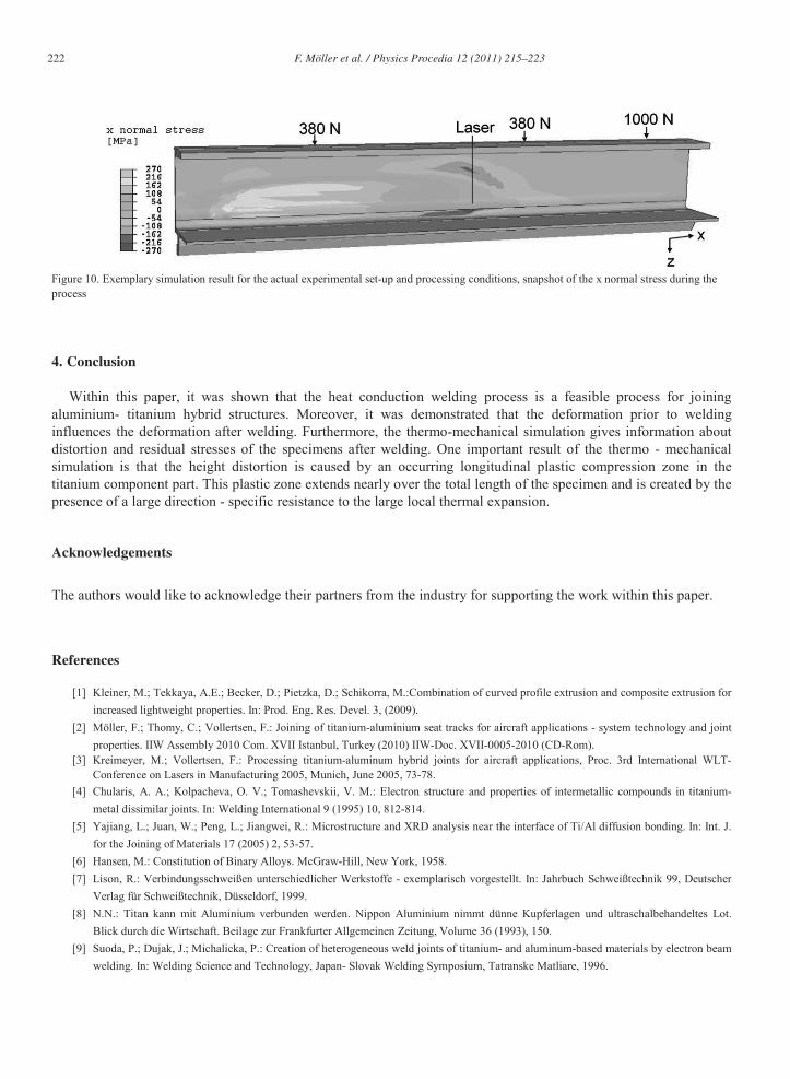
222 F. Möller et al. / Physics Procedia 12 (2011) 215–223
Figure 10. Exemplary simulation result for the actual experimental set-up and processing conditions, snapshot of the x normal stress during the process
4. Conclusion
Within this paper, it was shown that the heat conduction welding process is a feasible process for joining aluminium- titanium hybrid structures. Moreover, it was demonstrated that the deformation prior to welding influences the deformation after welding. Furthermore, the thermo-mechanical simulation gives information about distortion and residual stresses of the specimens after welding. One important result of the thermo - mechanical simulation is that the height distortion is caused by an occurring longitudinal plastic compression zone in the titanium component part. This plastic zone extends nearly over the total length of the specimen and is created by the presence of a large direction - specific resistance to the large local thermal expansion.
Acknowledgements
The authors would like to acknowledge their partners from the industry for supporting the work within this paper.
References
[1] Kleiner, M.; Tekkaya, A.E.; Becker, D.; Pietzka, D.; Schikorra, M.:Combination of curved profile extrusion and composite extrusion for increased lightweight properties. In: Prod. Eng. Res. Devel. 3, (2009).
[2] Möller, F.; Thomy, C.; Vollertsen, F.: Joining of titanium-aluminium seat tracks for aircraft applications - system technology and joint properties. IIW Assembly 2010 Com. XVII Istanbul, Turkey (2010) IIW-Doc. XVII-0005-2010 (CD-Rom).
[3] Kreimeyer, M.; Vollertsen, F.: Processing titanium-aluminum hybrid joints for aircraft applications, Proc. 3rd International WLT-Conference on Lasers in Manufacturing 2005, Munich, June 2005, 73-78.
[4] Chularis, A. A.; Kolpacheva, O. V.; Tomashevskii, V. M.: Electron structure and properties of intermetallic compounds in titanium-metal dissimilar joints. In: Welding International 9 (1995) 10, 812-814.
[5] Yajiang, L.; Juan, W.; Peng, L.; Jiangwei, R.: Microstructure and XRD analysis near the interface of Ti/Al diffusion bonding. In: Int. J. for the Joining of Materials 17 (2005) 2, 53-57.
[6] Hansen, M.: Constitution of Binary Alloys. McGraw-Hill, New York, 1958. [7] Lison, R.: Verbindungsschweißen unterschiedlicher Werkstoffe - exemplarisch vorgestellt. In: Jahrbuch Schweißtechnik 99, Deutscher
Verlag für Schweißtechnik, Düsseldorf, 1999. [8] N.N.: Titan kann mit Aluminium verbunden werden. Nippon Aluminium nimmt dünne Kupferlagen und ultraschalbehandeltes Lot.
Blick durch die Wirtschaft. Beilage zur Frankfurter Allgemeinen Zeitung, Volume 36 (1993), 150. [9] Suoda, P.; Dujak, J.; Michalicka, P.: Creation of heterogeneous weld joints of titanium- and aluminum-based materials by electron beam
welding. In: Welding Science and Technology, Japan- Slovak Welding Symposium, Tatranske Matliare, 1996.

F. Möller et al. / Physics Procedia 12 (2011) 215–223 223
[10] Fuji, A.; Ameyama, K.; North, T.H.: Influence of silicon in aluminium on the mechanical properties of titanium/aluminum friction joints. In: Journal of Materials Science 30 (1995) 20, 5185-5191.
[11] Kreimeyer, M.; Wagner, F.; Vollertsen, F.: Laser processing of aluminum-titanium-tailored blanks. Optics and Lasers in Engineering 43 (2005) 9, 1021-1035.
[12] Kreimeyer, M.; Wagner, F.; Zerner, I.; Sepold, G.: Laserstrahlfügen von Aluminium mit Titan unter Verwendung eines optimierten Arbeitskopfs. Proc. Löt 01, Aachen, DVS-Berichte 212, DVS-Verlag: Düsseldorf 2001, 317-321.
[13] Seefeld, T.; Kreimeyer, M.; Wagner, F.; Sepold, G.: Laserstrahlfügen von Mischverbindungen. 4. Laser-Anwenderforum. Bremen 2002, 215-224.
[14] Neugebauer, R.; Meyer, L. W.; Halle, T.; Popp, M.; Fritsch, S.; John, C.; Manufacture of a β-titanium hollow shaft by incremental forming, In: Prod. Eng. Res. Devel. 4, (2010).
[15] Schumacher, J.; Irretier, A.; Kocik, R.; Tinscher, R.; Kessler, O.; Sotirov, N.; Bomas, H.: Investigation of Laser-Beam Joined Titanium-Aluminum Hybrid Structures Applied Production Technology (APT’07), eds.: F. Vollertsen, C. Thomy. Bremen (2010), 149-160.