Embed Size (px)
Citation preview
Int J CARS (2016) 11:1109–1119DOI 10.1007/s11548-016-1393-4
ORIGINAL ARTICLE
Combined 2D and 3D tracking of surgical instrumentsfor minimally invasive and robotic-assisted surgery
Xiaofei Du1 · Maximilian Allan1 · Alessio Dore3 · Sebastien Ourselin2 ·David Hawkes2 · John D. Kelly4 · Danail Stoyanov1
Received: 11 February 2016 / Accepted: 17 March 2016 / Published online: 2 April 2016© The Author(s) 2016. This article is published with open access at Springerlink.com
AbstractPurpose Computer-assisted interventions for enhancedmin-imally invasive surgery (MIS) require tracking of the surgicalinstruments. Instrument tracking is a challenging problemin both conventional and robotic-assisted MIS, but vision-based approaches are a promising solution with minimalhardware integration requirements. However, vision-basedmethods suffer from drift, and in the case of occlusions, shad-ows and fast motion, they can be subject to complete tracking
Electronic supplementary material The online version of thisarticle (doi:10.1007/s11548-016-1393-4) contains supplementarymaterial, which is available to authorized users.
B Xiaofei [email protected]
Maximilian [email protected]
Alessio [email protected]
Sebastien [email protected]
David [email protected]
John D. [email protected]
Danail [email protected]
1 Centre for Medical Image Computing, Department ofComputer Science, University College London, London, UK
2 Centre for Medical Image Computing, Department ofMedical Physics, University College London, London, UK
3 WIREWAX, London, UK
4 Division of Surgery and Interventional Science,University College London, London, UK
failure.Methods In this paper, we develop a 2D tracker based ona Generalized Hough Transform using SIFT features whichcan both handle complex environmental changes and recoverfrom tracking failure. We use this to initialize a 3D tracker ateach frame which enables us to recover 3D instrument poseover long sequences and even during occlusions.Results We quantitatively validate our method in 2D and3D with ex vivo data collected from a DVRK controller aswell as providing qualitative validation on robotic-assistedin vivo data.Conclusions We demonstrate from our extended sequencesthat our method provides drift-free robust and accurate track-ing. Our occlusion-based sequences additionally demon-strate that our method can recover from occlusion-basedfailure. In both cases,we showan improvement over using3Dtracking alone suggesting that combining 2Dand 3D trackingis a promising solution to challenges in surgical instrumenttracking.
Keywords Instrument tracking and detection · Minimallyinvasive surgery · Robot-assisted surgery · Surgical vision
Introduction
Detection and tracking of surgical instruments can providean important information component of computer-assistedsurgery (CAS) forMIS [22]. Control systems which can sup-ply automated visual servoing [18], soft motion constraints[19] and tactile feedback [15] are reliant on knowing posi-tional information about both the shaft and the tip of thearticulated instrument. Hardware-based solutions such asoptical tracking systems using fiducial markers [10] require
123
1110 Int J CARS (2016) 11:1109–1119
modification to the instrument design posing ergonomic chal-lenges and additionally suffer from robustness issues dueto line-of-sight requirements. Direct use of robotic jointencoders and forward kinematics to track instruments ispossible in robot-assisted interventions; however, tendon-driven systems, such as da Vinci® (Intuitive Surgical Inc.,CA), introduce errors in the position information which usu-ally requires correction that can be achieved through visualmethods [17,18]. Entirely image-based solutions [3,21,23]directly estimate the instrument pose in the reference frameof the observing camera. This avoids complex calibrationroutines and can be implemented entirely through softwarewhich allows them to be applied retrospectively and withoutmodification to the instruments or the surgical workflow.
Early image-based methods predominantly estimated theinstrument pose in 2D by estimating image-based transla-tion parameters, scale and in-plane rotationwithout explicitlymodeling the 3D shape of the instrument. These have beenbased around low-level image processing [20] which accu-mulate handcrafted visual features andmore complex learneddiscriminative models [6,23] which track an instrument byperforming detection independently on each frame. Suchmethods are typically fast and robust, handling complexand fast motion as well as recovery when the instrument isoccluded by the field of view of the camera or smoke andtissue as they perform a global or semi-global search of theentire image for the tracked instrument. Fewer methods haveattempted to estimate the 3D pose of the instruments directlyfrom image data. This typically is a much more complexproblem as it involves estimating three additional degreesof freedom (DOF) from very weak small baseline stereoor monocular cues. However, it provides additional benefitsover 2D methods as it allows reasoning about instrument–instrument occlusions and interactions with tissue surfaces.Most of these methods focus on the alignment of a 3Dmodelwith a probabilistic classification of the image [1,2,16]whichallows the fusion of geometric constraints with image datawithout an offline learning phase. A significant challengewith 3D tracking methods is that they commonly fail whenthe instrument motion is fast or complex, as they restrict theparameter search to local regions close to the estimated para-meters from the previous frame. In many cases, this can leadto drift which requires a manual reset of the tracking.
In this paper, we present a new method which combinesthe strengths of a novel 2D tracker with a preexisting 3Dtracking method [3] allowing us to robustly track surgicalinstruments through sequences that contain occlusions andchallenging motion which cause the 3D tracker to fail. Weachieve this by performing global tracking-by-detection in2D with a keypoint-based tracker which is used to initial-ize the 3D tracker with image-based translation and rotationparameters as well as an estimate of scale. We then per-form a normal gradient-based optimization to estimate the
full set of 3D parameters. We quantitatively validate ourmethod using ex vivo data collected from a DVRK controllerand forward kinematics and additionally provide convincingqualitative validation on in vivo robot-assisted prostatectomysequences. Our validation shows the our method providesstate-of-the-art 2D tracking performance and significantlyimproves tracking accuracy in 3D. In the ex vivo sequences,we restrict the motion of rigid 3D tracking as the method weuse [3] does notmodel articulations of the instrument tip. Ourvalidation shows the our method provides state-of-the-art 2Dtracking performance and improves tracking accuracy in 3D.
Methods
Our method assumes that we have the 3D pose of the instru-ment in the first frame which we use to initialize a 2Dbounding box (u′, v′, w, h) (see Fig. 1) around the instru-ment head where (u′, v′) is the pixel coordinates of top leftcorner of the bounding box which has width w and height h.We define the 2D detection problem as the estimation of theparametersλ2D = (u, v, θ, s) and the 3Destimation problemas the estimation of the parameters λ3D = (x, y, z, φ, ψ, θ̂ ),where (u, v) are the pixel coordinates of the center of theinstrument head and θ is the pitch/in-plane rotation of theinstrument shaft around the optical axis. (x, y, z) are the3D translation coordinate in metric units from the cameracoordinate system origin to the instrument coordinate systemorigin, and φ,ψ, θ̂ are the x, y, z rotations of the instrumentin 3D, respectively. For each new input frame, we detectthe instrument, estimating the 2D parameters λ2D using ournew tracker. Using these parameters, we then initialize a pre-viously developed, open-source 3D tracker [3] which thenconverges using gradient descent to estimate the full 3D para-meter vector λ3D .
Generalized Hough transform for 2D detection
To estimate λ2D , we implement a keypoint-based trackerwhich relies on a Generalized Hough Transform (GHT)[5] and a global histogram segmentation model. The GHTextends the well-known Hough Transform to detect arbitraryshapes as maxima in a parameter space by describing shapesas collections of spatial features in a local coordinate system.Given an example image template containing the object ofinterest, a reference point which serves as the origin of thelocal coordinates is computed, usually as the center of thetemplate window. Then, for keypoint-based features (e.g.,SIFT [13]) in the template image, the feature orientationand the relative displacement and orientation to the refer-ence point are computed and stored in a database known asan R-table, which fully defines the target object. To performdetection with the GHT, keypoints in a new image are com-
123
Int J CARS (2016) 11:1109–1119 1111
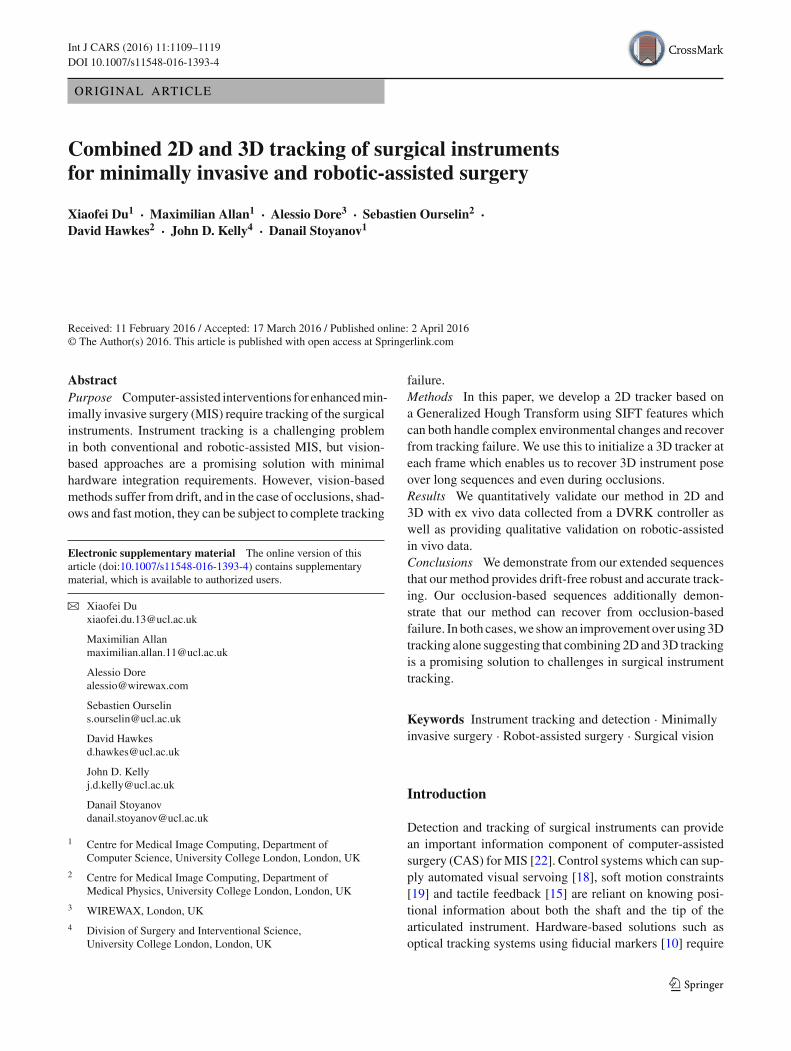
Fig. 1 The left image shows the 2D detection and estimation of the parameters λ2D which are then used a to initialize the 3D parameters λ3D .After the 3D pose is estimated, a new frame is loaded b and 2D detection begins again
puted and matched to the stored keypoints in the R-table.Each matched keypoint then “votes” for the origin of thecoordinate system, and the center is chosen as the referencepoint with the most votes.
Initializing the model
Given a sequence of m frames {It }mt=1 and the 2D boundingbox (u′, v′, w, h) on the template frame I1, we detect theparameters λ2D = (u, v, θ, s) on every input frame. Theobject model M is represented by a set of keypoints
M = {(f i,t=1, di , si,t=1)}ni=1 (1)
where f i,t=1 denotes the i th keypoint on the model, di rep-resents the distance between keypoint f i , and the center ofthe instrument head (u, v). si,t ∈ {0, 1} is the voting state ofkeypoint f i at frame t : 0 for negative and 1 for positive. It ispositive if the corresponding keypoint has contributed for thevoting of the detected center; otherwise, it is negative. Thevoting states for all keypoints are initialized as positive forthe template frame I1
si,t=1 = 1 ∀i ∈ [1, n] (2)
For each input frame It with t > 1, the keypoints in themodel are matched. We gather the matched correspondingkeypoints as the vote set FV .
FV = {(f i,t , wi,t )} ∀i ∈ [1, n] (3)
wherewi,t is the votingweight for eachmatchedkeypoint f i,t ,which is defined based on the segmentationmodel introducedin Sect. 2.3.
Histogram-based segmentation model
To adapt object model accounting for appearance changes,we are inspired by the work of [7,8] and we implementeda global probabilistic model based on color histogram byusing a recursive Bayesian formulation to better discriminateforeground and background.
The foreground probability of a pixel at frame t is basedon the segmentation of previous frame t − 1.
p(ct = 1|y1:t ) = Z−1∑
ct−1
p(yt |ct = 1)p(ct = 1|ct−1)
×p(ct−1 = 1|y1:t−1) (4)
where ct is the class of the pixel at frame t : 0 for backgroundand1 for foreground, y1:t is the pixel’s color from frame1 to t ,and Z is a normalization constant to keep the probabilitiessum to 1. The color distribution p(yt |ct ) is built with HSVcolor histograms with 12 × 12 bins for H and S channelsand 8 separate bins for V channel. We omit the backgroundprobability p(ct = 0|y1:t ) here since it is similar to Eq. 4.The transition probabilities for foreground and backgroundp(ct |ct−1) where c ∈ {0, 1} are empirical choices as in [8],which are not very sensitive.
To detect more boundary keypoints, the bounding box isusually slightly larger than the object, which includes morebackground pixels. So instead of initializing the histogramfrom the bounding box on the template image as in [8], weinitialize it from the detection result from the first frame afterlocating the object center. It is assumed that the positive key-points are most likely located on the object, so we collect allthe positive keypoint into FPos
FPos = {f i,t } if si,t = 1 ∀f i,t ∈ FV (5)
123
1112 Int J CARS (2016) 11:1109–1119
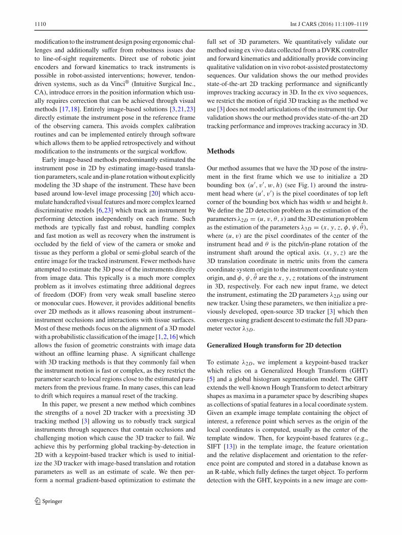
Fig. 2 Segmentation model initialization and update strategy: a imageregion inside the convex hull (green polygon) of the positive keypoints(green circle) is used to initialize and update the foreground histogram;filled circle with magenta color indicates the reference center; b fore-
ground probability colormap illustration, in which blue color indicateslow probability, while red color indicates higher probability; c fore-ground/background classification binary map based on the probabilitymodel
The foreground histogram is then initialized from the imageregion inside the convex hull of all the positive keypointsCH(FPos), which contains less background pixels. Thebackground histogram is initialized from the image regionsurrounding the detected object bounding box (with somemargin between). For the following frames, the color dis-tributions are adapted in the same way as the initialization(shown in Fig. 2)
p(yt |ct = 1) = δp(y|y ∈ CH(FPos))
+(1 − δ)p(yt−1|ct−1 = 1) (6)
where δ = 0.1 is the model update factor.The voting weight of a keypoint is defined as the mean
foreground probability of the image patch surrounding thekeypoint
wi,t = p(ct = 1|f i,t ) (7)
During the voting process, we set the weight thresh-old wthres = 0.5, only keypoints with higher weight (wi,t >
wthres) participate in the voting process, and the weightedvotes accumulated based on the segmentation model. Inregard to the voting, we developed a rotation-invariant votingscheme in Sect. 2.4.
Rotation-invariant Hough voting scheme
When the object undergoes scale change or in-plane rota-tion, the voting also needs to rotate and scale in order tolocate the object center. Scale and rotation information canbe obtained frommost feature detectors, but since it is usuallynot reliable enough, in [14], the authors analyzed the pairwiseEuclidean distance and angular change between keypoints.
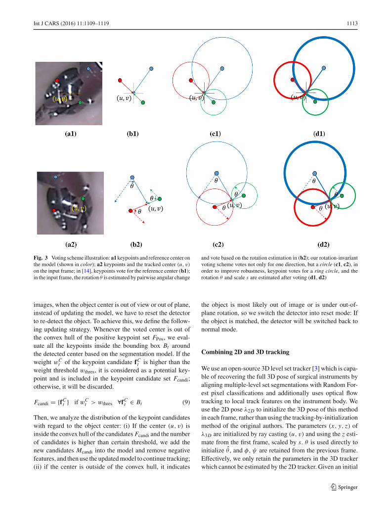
We illustrated their voting scheme and ours in Fig. 3: Key-points on the model and on the input frame are matched inFig. 3a1, a2; then in the input frame, median pairwise angularchange between keypoints is computed by comparing withthe initial constellation in Fig. 3b1, and correspondent key-points rotate votes based on the median angular change θ ′in Fig. 3b2. It displays the ideal situation for rotation estima-tion, but when the percentage of outliers is high, votes willprobably miss shoot the center based on unreliable rotationestimation. We develop a rotation-invariant voting strategyshown in Fig. 3c1, c2. For each keypoint, instead of vot-ing for only one direction, it votes for a circle. In this way,our vote scheme does not rely on any pre-estimation of rota-tion, and the maximum vote still accumulated at the centerwithout any potential error induced by the pre-voting rota-tion estimation. In order to improve the overshooting or fallshort situation for scale estimation or out-of-plane rotation,wemake it more robust by voting for a ring circle in Fig. 3d1,d2. The thickness ratio rd is set to be [0.95, 1.05]. The ini-tial scale st=1 is set to be 1.0, the radius of the voting circledi,t is based on the scale of the previous frame st−1, and thedistance of the keypoint to the reference center of the modeldi is
di,t = rd ∗ di ∗ st−1 (8)
After voting, the scale st and rotation θt are estimated basedon the scale change and angle change of all the positive key-points.
Model adaptation
One of the challenges for visual tracking is how and when toadapt the object model to cope with appearance changes dueto deformation, illumination variations, etc. In endoscopic
123
Int J CARS (2016) 11:1109–1119 1113
Fig. 3 Voting scheme illustration:a1keypoints and reference center onthe model (shown in color); a2 keypoints and the tracked center (u, v)
on the input frame; in [14], keypoints vote for the reference center (b1);in the input frame, the rotation θ is estimated by pairwise angular change
and vote based on the rotation estimation in (b2); our rotation-invariantvoting scheme votes not only for one direction, but a circle (c1, c2), inorder to improve robustness, keypoint votes for a ring circle, and therotation θ and scale s are estimated after voting (d1, d2)
images, when the object center is out of view or out of plane,instead of updating the model, we have to reset the detectorto re-detect the object. To achieve this, we define the follow-ing updating strategy. Whenever the voted center is out ofthe convex hull of the positive keypoint set FPos, we eval-uate all the keypoints inside the bounding box Bt aroundthe detected center based on the segmentation model. If theweight wC
t of the keypoint candidate fCt is higher than theweight threshold wthres, it is considered as a potential key-point and is included in the keypoint candidate set Fcandi;otherwise, it will be discarded.
Fcandi = {fCt } if wCt > wthres ∀fCt ∈ Bt (9)
Then, we analyze the distribution of the keypoint candidateswith regard to the object center: (i) If the center (u, v) isinside the convex hull of the candidates Fcandi and the numberof candidates is higher than certain threshold, we add thenew candidates Mcandi into the model and remove negativefeatures, and then use the updatedmodel to continue tracking;(ii) if the center is outside of the convex hull, it indicates
the object is most likely out of image or is under out-of-plane rotation, so we switch the detector into reset mode: Ifthe object is matched, the detector will be switched back tonormal mode.
Combining 2D and 3D tracking
We use an open-source 3D level set tracker [3] which is capa-ble of recovering the full 3D pose of surgical instruments byaligning multiple-level set segmentations with Random For-est pixel classifications and additionally uses optical flowtracking to local track features on the instrument body. Weuse the 2D pose λ2D to initialize the 3D pose of this methodin each frame, rather than using the tracking-by-initializationmethod of the original authors. The parameters (x, y, z) ofλ3D are initialized by ray casting (u, v) and using the z esti-mate from the first frame, scaled by s. θ is used directly toinitialize θ̂ , and φ,ψ are retained from the previous frame.Effectively, we only retain the parameters in the 3D trackerwhich cannot be estimated by the 2D tracker. Given an initial
123
1114 Int J CARS (2016) 11:1109–1119
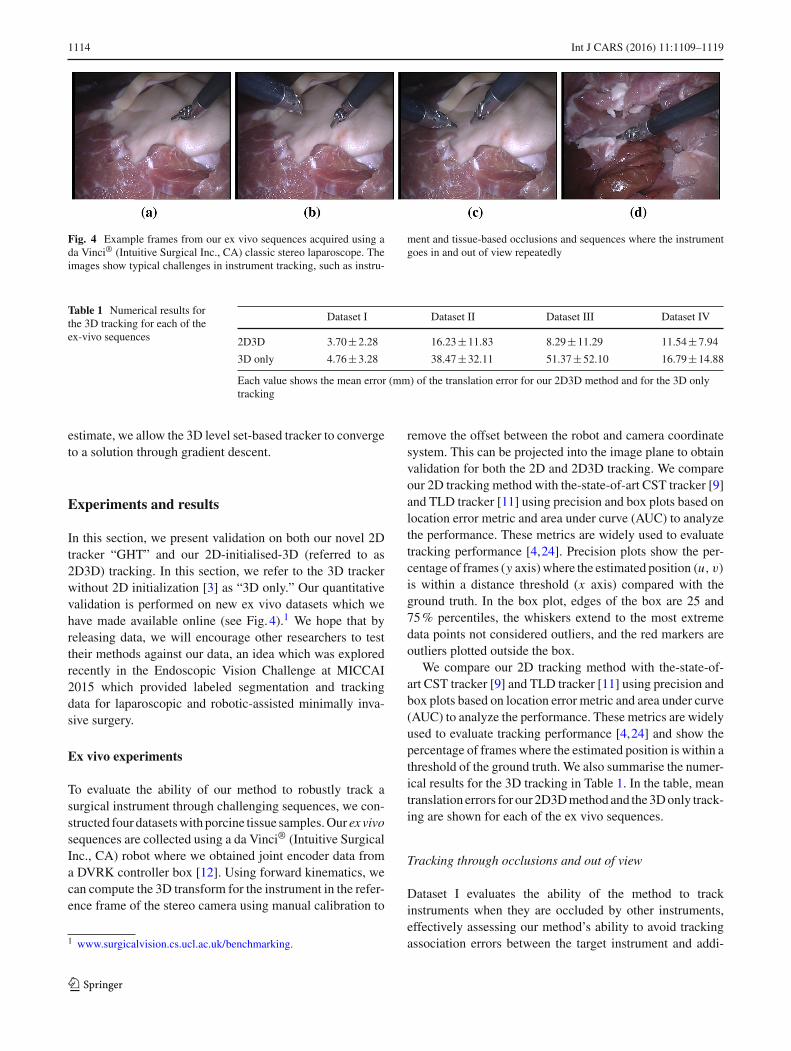
Fig. 4 Example frames from our ex vivo sequences acquired using ada Vinci® (Intuitive Surgical Inc., CA) classic stereo laparoscope. Theimages show typical challenges in instrument tracking, such as instru-
ment and tissue-based occlusions and sequences where the instrumentgoes in and out of view repeatedly
Table 1 Numerical results forthe 3D tracking for each of theex-vivo sequences
Dataset I Dataset II Dataset III Dataset IV
2D3D 3.70±2.28 16.23±11.83 8.29±11.29 11.54±7.94
3D only 4.76±3.28 38.47±32.11 51.37±52.10 16.79±14.88
Each value shows the mean error (mm) of the translation error for our 2D3D method and for the 3D onlytracking
estimate, we allow the 3D level set-based tracker to convergeto a solution through gradient descent.
Experiments and results
In this section, we present validation on both our novel 2Dtracker “GHT” and our 2D-initialised-3D (referred to as2D3D) tracking. In this section, we refer to the 3D trackerwithout 2D initialization [3] as “3D only.” Our quantitativevalidation is performed on new ex vivo datasets which wehave made available online (see Fig. 4).1 We hope that byreleasing data, we will encourage other researchers to testtheir methods against our data, an idea which was exploredrecently in the Endoscopic Vision Challenge at MICCAI2015 which provided labeled segmentation and trackingdata for laparoscopic and robotic-assisted minimally inva-sive surgery.
Ex vivo experiments
To evaluate the ability of our method to robustly track asurgical instrument through challenging sequences, we con-structed four datasetswith porcine tissue samples.Our ex vivosequences are collected using a da Vinci® (Intuitive SurgicalInc., CA) robot where we obtained joint encoder data froma DVRK controller box [12]. Using forward kinematics, wecan compute the 3D transform for the instrument in the refer-ence frame of the stereo camera using manual calibration to
1 www.surgicalvision.cs.ucl.ac.uk/benchmarking.
remove the offset between the robot and camera coordinatesystem. This can be projected into the image plane to obtainvalidation for both the 2D and 2D3D tracking. We compareour 2D tracking method with the-state-of-art CST tracker [9]and TLD tracker [11] using precision and box plots based onlocation error metric and area under curve (AUC) to analyzethe performance. These metrics are widely used to evaluatetracking performance [4,24]. Precision plots show the per-centage of frames (y axis)where the estimated position (u, v)
is within a distance threshold (x axis) compared with theground truth. In the box plot, edges of the box are 25 and75% percentiles, the whiskers extend to the most extremedata points not considered outliers, and the red markers areoutliers plotted outside the box.
We compare our 2D tracking method with the-state-of-art CST tracker [9] and TLD tracker [11] using precision andbox plots based on location error metric and area under curve(AUC) to analyze the performance. These metrics are widelyused to evaluate tracking performance [4,24] and show thepercentage of frames where the estimated position is within athreshold of the ground truth. We also summarise the numer-ical results for the 3D tracking in Table 1. In the table, meantranslation errors for our 2D3Dmethod and the3Donly track-ing are shown for each of the ex vivo sequences.
Tracking through occlusions and out of view
Dataset I evaluates the ability of the method to trackinstruments when they are occluded by other instruments,effectively assessing our method’s ability to avoid trackingassociation errors between the target instrument and addi-
123
Int J CARS (2016) 11:1109–1119 1115
0200
400600
0
200
400
6000
500
1000
1500
XY
Fra
me
GTCSTTLDGHT
(a)
0 10 20 30 40 500
0.1
0.2
0.3
0.4
0.5
0.6
0.7
0.8
0.9
1Precision plots
Location error threshold (pixel)
Pre
cisi
on
CST [0.36115]TLD [0.71314]GHT [0.73299]
(b)
0
50
100
150
200
250
300
350
400
CST [106.7928] TLD [10.3312] GHT [7.2111]
Box plots
Loca
tion
erro
r (pi
xel)
(c)
Frame no.0 100 200 300 400 500 600
Posi
tion
(mm
)
-10
-5
0
5
10
15
20Translation x
2D3D3DGround Truth
(d)Frame no.
0 100 200 300 400 500 600
Posi
tion
(mm
)
-30
-25
-20
-15
-10
-5
0
5
10Translation y
2D3D3DGround Truth
(e)Frame no.
0 100 200 300 400 500 600
Posi
tion
(mm
)
90
95
100
105
110
115
120
125Translation z
2D3D3DGround Truth
(f)
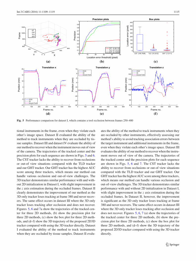
Fig. 5 Performance comparison for dataset I, which contains a tool occlusion between frames 250–400
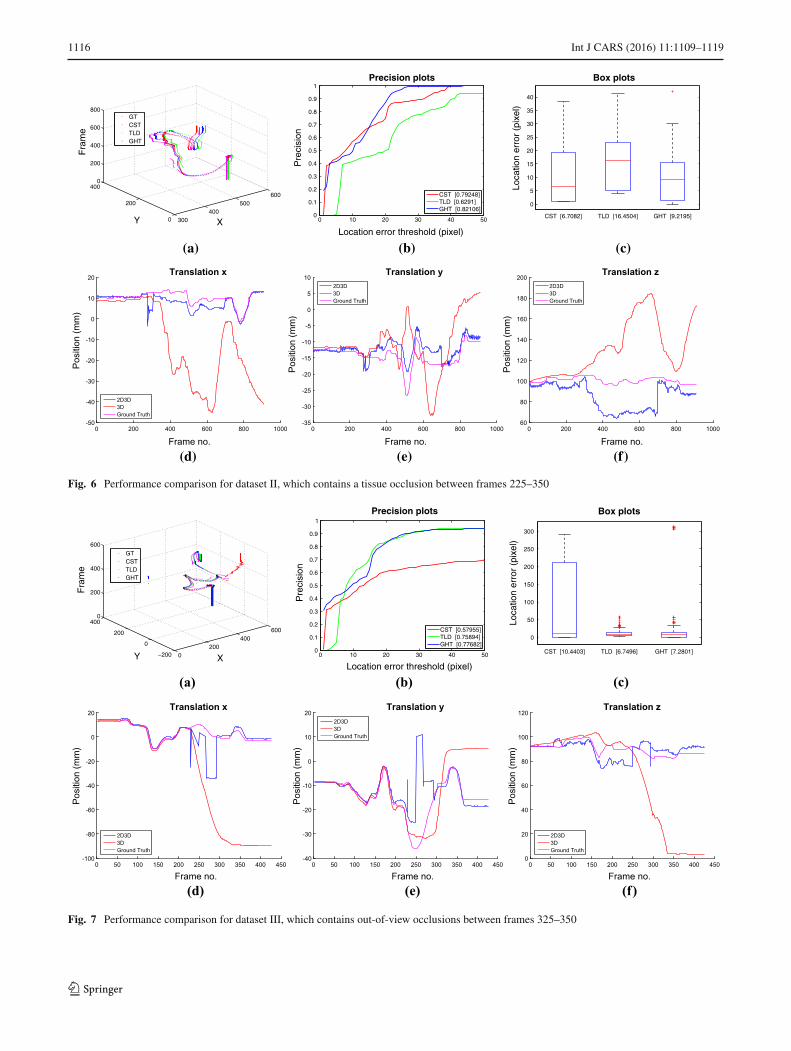
tional instruments in the frame, even when they violate eachother’s image space. Dataset II evaluated the ability of themethod to track instruments when they are occluded by tis-sue samples. Dataset III and dataset IV evaluate the ability ofourmethod to recoverwhen the instrumentmoves out of viewof the camera. The trajectories of the tracked center and theprecision plots for each sequence are shown in Figs. 5 and 6.The CST tracker lacks the ability to recover from occlusionsor out-of view situations compared with the TLD trackerand our GHT tracker. Our GHT tracker has the highest AUCscore among three trackers, which means our method canhandle various occlusion and out-of-view challenges. The3D tracker demonstrates similar performance with and with-out 2D initialization in Dataset I, with slight improvement inthe z axis estimation during the occluded frames. Dataset IIclearly demonstrates the improvement of our method as the3D only tracker loses tracking at frame 380 and never recov-ers. The same effect occurs in dataset III where the 3D onlytracker loses tracking after occlusion and does not recover.Figures 5, 6 and 7a show the trajectories of the tracked cen-ter for three 2D methods, (b) show the precision plot forthree 2D methods, (c) show the box plot for three 2D meth-ods, and (d–f) show the 3D trajectory of the proposed 2D3Dtracker compared with using the 3D tracker directly. DatasetI evaluated the ability of the method to track instrumentswhen they are occluded by tissue samples. Dataset II evalu-
ates the ability of the method to track instruments when theyare occluded by other instruments, effectively assessing ourmethod’s ability to avoid tracking association errors betweenthe target instrument and additional instruments in the frame,even when they violate each other’s image space. Dataset IIIevaluates the ability of ourmethod to recoverwhen the instru-ment moves out of view of the camera. The trajectories ofthe tracked center and the precision plots for each sequenceare shown in Figs. 5, 6 and 7. The CST tracker lacks theability to recover from occlusions or out-of view situationscompared with the TLD tracker and our GHT tracker. OurGHT tracker has the highestAUCscore among three trackers,which means our method can handle various occlusion andout-of-view challenges. The 3D tracker demonstrates similarperformance with and without 2D initialization in Dataset I,with slight improvement in the z axis estimation during theoccluded frames. In Dataset II, however, the improvementis significant as the 3D only tracker loses tracking at frame380 and never recovers. The same effect occurs in dataset IIIwhere the 3D only tracker loses tracking after occlusion anddoes not recover. Figures 5, 6, 7 (a) show the trajectories ofthe tracked center for three 2D methods, (b) show the pre-cision plot for three 2D methods, (c) show the box plot forthree 2D methods, and (d–f) show the 3D trajectory of theproposed 2D3D tracker compared with using the 3D trackerdirectly.
123
1116 Int J CARS (2016) 11:1109–1119
300400
500600
0
200
4000
200
400
600
800
XY
Fra
me
GTCSTTLDGHT
(a)
0 10 20 30 40 500
0.1
0.2
0.3
0.4
0.5
0.6
0.7
0.8
0.9
1Precision plots
Location error threshold (pixel)
Pre
cisi
on
CST [0.79248]TLD [0.6291]GHT [0.82106]
(b)
0
5
10
15
20
25
30
35
40
CST [6.7082] TLD [16.4504] GHT [9.2195]
Box plots
Loca
tion
erro
r (p
ixel
)
(c)
Frame no.0 200 400 600 800 1000
Posi
tion
(mm
)
-50
-40
-30
-20
-10
0
10
20Translation x
2D3D3DGround Truth
(d)Frame no.
0 200 400 600 800 1000
Posi
tion
(mm
)
-35
-30
-25
-20
-15
-10
-5
0
5
10Translation y
2D3D3DGround Truth
(e)Frame no.
0 200 400 600 800 1000
Posi
tion
(mm
)
60
80
100
120
140
160
180
200Translation z
2D3D3DGround Truth
(f)
Fig. 6 Performance comparison for dataset II, which contains a tissue occlusion between frames 225–350
0200
400600
−200
0
200
4000
200
400
600
XY
Fra
me
GTCSTTLDGHT
(a)
0 10 20 30 40 500
0.1
0.2
0.3
0.4
0.5
0.6
0.7
0.8
0.9
1
Precision plots
Location error threshold (pixel)
Pre
cisi
on
CST [0.57955]TLD [0.75894]GHT [0.77682]
(b)
0
50
100
150
200
250
300
CST [10.4403] TLD [6.7496] GHT [7.2801]
Box plotsLo
catio
n er
ror
(pix
el)
(c)
Frame no.0 50 100 150 200 250 300 350 400 450
Posi
tion
(mm
)
-100
-80
-60
-40
-20
0
20Translation x
2D3D3DGround Truth
(d)Frame no.
0 50 100 150 200 250 300 350 400 450
Posi
tion
(mm
)
-40
-30
-20
-10
0
10
20Translation y
2D3D3DGround Truth
(e)Frame no.
0 50 100 150 200 250 300 350 400 450
Posi
tion
(mm
)
0
20
40
60
80
100
120Translation z
2D3D3DGround Truth
(f)
Fig. 7 Performance comparison for dataset III, which contains out-of-view occlusions between frames 325–350
123
Int J CARS (2016) 11:1109–1119 1117
0500
1000
0200
400600
0
1000
2000
3000
4000
5000
XY
Fra
me
GTCSTTLDGHT
(a)
0 10 20 30 40 500
0.1
0.2
0.3
0.4
0.5
0.6
0.7
0.8
0.9
1
Precision plots
Location error threshold (pixel)
Pre
cisi
on
CST [0.33056]TLD [0.58308]GHT [0.58882]
(b)
0 10 20 30 40 500
0.1
0.2
0.3
0.4
0.5
0.6
0.7
0.8
0.9
1
Precision plots
Location error threshold (pixel)
Pre
cisi
on
CST [0.33242]TLD [0.58603]GHT [0.62597]
(c)
0
50
100
150
200
250
300
350
400
450
CST [37.4433] TLD [17.9354] GHT [14.1421]
Box plots
Loca
tion
erro
r (p
ixel
)
(d)
Frame no.0 500 1000 1500 2000 2500 3000 3500 4000 4500
Posi
tion
(mm
)
-40
-30
-20
-10
0
10
20
30
40Translation x
2D3D3DGround Truth
(e)Frame no.
0 500 1000 1500 2000 2500 3000 3500 4000 4500
Posi
tion
(mm
)
-50
-40
-30
-20
-10
0
10
20
30Translation y
2D3D3DGround Truth
(f)Frame no.
0 500 1000 1500 2000 2500 3000 3500 4000 4500
Posi
tion
(mm
)
0
50
100
150Translation z
2D3D3DGround Truth
(g)
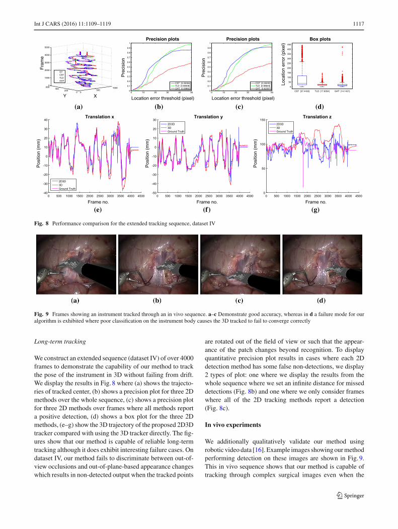
Fig. 8 Performance comparison for the extended tracking sequence, dataset IV
Fig. 9 Frames showing an instrument tracked through an in vivo sequence. a–c Demonstrate good accuracy, whereas in d a failure mode for ouralgorithm is exhibited where poor classification on the instrument body causes the 3D tracked to fail to converge correctly
Long-term tracking
We construct an extended sequence (dataset IV) of over 4000frames to demonstrate the capability of our method to trackthe pose of the instrument in 3D without failing from drift.We display the results in Fig. 8 where (a) shows the trajecto-ries of tracked center, (b) shows a precision plot for three 2Dmethods over the whole sequence, (c) shows a precision plotfor three 2D methods over frames where all methods reporta positive detection, (d) shows a box plot for the three 2Dmethods, (e–g) show the 3D trajectory of the proposed 2D3Dtracker compared with using the 3D tracker directly. The fig-ures show that our method is capable of reliable long-termtracking although it does exhibit interesting failure cases. Ondataset IV, our method fails to discriminate between out-of-view occlusions and out-of-plane-based appearance changeswhich results in non-detected output when the tracked points
are rotated out of the field of view or such that the appear-ance of the patch changes beyond recognition. To displayquantitative precision plot results in cases where each 2Ddetection method has some false non-detections, we display2 types of plot: one where we display the results from thewhole sequence where we set an infinite distance for misseddetections (Fig. 8b) and one where we only consider frameswhere all of the 2D tracking methods report a detection(Fig. 8c).
In vivo experiments
We additionally qualitatively validate our method usingrobotic video data [16]. Example images showingourmethodperforming detection on these images are shown in Fig. 9.This in vivo sequence shows that our method is capable oftracking through complex surgical images even when the
123
1118 Int J CARS (2016) 11:1109–1119
instrument undergoes articulation, which our method doesnot explicitly model.
Conclusions
In this paper, we present a novel GHT-based 2D tracker witha global histogram probabilistic segmentation model whichwe combine with a 3D tracking algorithm to robustly esti-mate the full 3D pose of instruments in minimally invasivesurgery. Our extensive ex vivo validation demonstrates thatour method is not only capable of tracking instruments overextended sequences but that it can also recover from trackingfailures and occlusions, a feature that has not been demon-strated in any prior 3D tracking work in a minimally invasivesurgical context. Future improvements to this method willfocus around removing the requirement on a manual initial-ization. This can potentially be achieved with an enforcedfixed position of the instrument, while the 3D pose estimatorconverges to a correct solution.
Acknowledgments We would like to acknowledge Simon Di Maioand Intuitive Surgical Inc., CA, for their support and input to thiswork. Xiaofei Du is supported by the China Scholarship Council (CSC)scholarship. Max Allan would like to acknowledge the financial sup-port of the Rabin Ezra foundation as well as EPSRC funding for DTPin Medical and Biomedical Imaging at University College London.Danail Stoyanov receives funding from the EPSRC (EP/N013220/1,EP/N022750/1), the EU-FP7 Project CASCADE (FP7-ICT-2913-601021) and the EU-Horizon2020 Project EndoVESPA (H2020-ICT-2015-688592).
Compliance with ethical standards
Conflict of interest The authors declare no conflict of interest.
Ethical standards All procedures performed in studies involvinghuman participants were in accordance with the ethical standards ofthe institutional and/or national research committee and with the 1964Helsinki Declaration and its later amendments or comparable ethicalstandards.
Informed consent Informed consent was obtained from all patientswho were included in the study.
Open Access This article is distributed under the terms of the CreativeCommons Attribution 4.0 International License (http://creativecommons.org/licenses/by/4.0/), which permits unrestricted use, distribution,and reproduction in any medium, provided you give appropriate creditto the original author(s) and the source, provide a link to the CreativeCommons license, and indicate if changes were made.
References
1. Allan M, Ourselin S, Thompson S, Hawkes DJ, Kelly J, StoyanovD (2013) Toward detection and localization of instruments in mini-mally invasive surgery. IEEE Trans Biomed Eng 60(4):1050–1058
2. AllanM, Thompson S, ClarksonMJ, Ourselin S, HawkesDJ, KellyJ, Stoyanov D (2014) 2d–3d pose tracking of rigid instruments
in minimally invasive surgery. Inf Process Comput Assist Interv8498:1–10
3. Allan M, Chang PL, Ourselin S, Hawkes DJ, Sridhar A, KellyJ, Stoyanov D (2015) Image based surgical instrument pose esti-mation with multi-class labelling and optical flow. In: Medicalimage computing and computer-assisted intervention–MICCAI2015, Springer, Berlin, pp 331–338
4. Babenko B, Yang MH, Belongie S (2011) Robust object trackingwith online multiple instance learning. IEEE Trans Pattern AnalMach Intell 33(8):1619–1632
5. BallardDH (1981)Generalizing the hough transform to detect arbi-trary shapes. Pattern Recognit 13(2):111–122
6. Bouget D, Benenson R, Omran M, Riffaud L, Schiele B, Jannin P(2015) Detecting surgical tools by modelling local appearance andglobal shape. IEEE Trans Med Imaging PP(99):1–1. doi:10.1109/TMI.2015.2450831
7. Collins RT, Liu Y, Leordeanu M (2005) Online selection of dis-criminative tracking features. IEEE Trans Pattern Anal Mach Intell27(10):1631–1643
8. Duffner S, Garcia C (2013) Pixeltrack: a fast adaptive algorithmfor tracking non-rigid objects. In: Proceedings of the IEEE inter-national conference on computer vision, pp 2480–2487
9. Henriques JF, Caseiro R, Martins P, Batista J (2012) Exploitingthe circulant structure of tracking-by-detection with kernels. In:Computer vision–ECCV 2012. Springer, Berlin, pp 702–715
10. Joskowicz L,MilgromC, Simkin A, Tockus L, Yaniv Z (1998) Fra-cas: a system for computer-aided image-guided long bone fracturesurgery. Comput Aided Surg 3(6):271–288
11. Kalal Z, Mikolajczyk K, Matas J (2012) Tracking-learning-detection. IEEE Trans Pattern Anal Mach Intell 34(7):1409–1422
12. Kazanzides P, Chen Z, Deguet A, Fischer G, Taylor R, Dimaio S(2014)Anopen-source research kit for the da vinci® surgical robot.In: 2014 IEEE international conference on robotics and automation(ICRA) (Hong Kong)
13. Lowe DG (2004) Distinctive image features from scale-invariantkeypoints. Int JComputVision 60(2):91–110. doi:10.1023/B:VISI.0000029664.99615.94
14. Nebehay G, Pflugfelder R (2014) Consensus-based matching andtracking of keypoints for object tracking. In: 2014 IEEE winterconference on applications of computer vision (WACV). IEEE, pp862–869
15. Okamura AM (2009) Haptic feedback in robot-assisted minimallyinvasive surgery. Curr Opin Urol 19(1):102
16. Pezzementi Z, Voros S, Hager GD (2009) Articulated object track-ing by rendering consistent appearance parts. In: IEEE internationalconference on robotics and automation, 2009. ICRA’09. IEEE, Sil-ver Spring, pp 3940–3947
17. Reiter A,Allen PK, ZhaoT (2012a) Feature classification for track-ing articulated surgical tools. In: Medical image computing andcomputer-assisted intervention–MICCAI 2012, Springer, pp 592–600
18. Reiter A, Allen PK, Zhao T (2012b) Learning features on roboticsurgical tools. In: 2012 IEEE computer society conference onCom-puter vision and pattern recognition workshops (CVPRW). IEEE,Silver Spring, pp 38–43
19. Ren J, Patel RV, McIsaac KA, Guiraudon G, Peters TM (2008)Dynamic 3-d virtual fixtures for minimally invasive beating heartprocedures. IEEE Trans Med Imaging 27(8):1061–1070
20. Speidel S, Kuhn E, Bodenstedt S, Röhl S, Kenngott H, Müller-Stich B, Dillmann R (2014) Visual tracking of da vinci instrumentsfor laparoscopic surgery. In: SPIE Medical Imaging, InternationalSociety for Optics and Photonics, pp 903608
21. Speidel S, Kroehnert A, Bodenstedt S, Kenngott H, Mueller-StichB, Dillmann R (2015) Image-based tracking of the suturing nee-dle during laparoscopic interventions. In: SPIE Medical Imaging,International Society for Optics and Photonics, pp 94,150B
123

Int J CARS (2016) 11:1109–1119 1119
22. Stoyanov D (2012) Surgical vision. Ann Biomed Eng 40(2):332–345
23. Sznitman R, Becker C, Fua P (2014) Fast part-based classifica-tion for instrument detection in minimally invasive surgery. In:Medical image computing and computer-assisted intervention–MICCAI 2014. Springer, Berlin, pp 692–699
24. Wu Y, Lim J, Yang MH (2013) Online object tracking: A bench-mark. In: 2013 IEEE conference on computer vision and patternrecognition (CVPR). IEEE, Silverspring, pp 2411–2418
123

![Atmel AT03030: QMatrix Touchpad – 2D Position …ww1.microchip.com/downloads/en/AppNotes/Atmel-42202...Atmel AT03030: QMatrix Touchpad – 2D Position Tracking [APPLICATION NOTE]](https://img.pdfslide.us/doc/110x75/5e82bfb366844315cb3c3385/atmel-at03030-qmatrix-touchpad-a-2d-position-ww1-atmel-at03030-qmatrix.jpg)