Embed Size (px)
Citation preview
BA_Combi-Regal_007_EN Page 1 of 19 pages Issued 07/2014
Original
User Manual
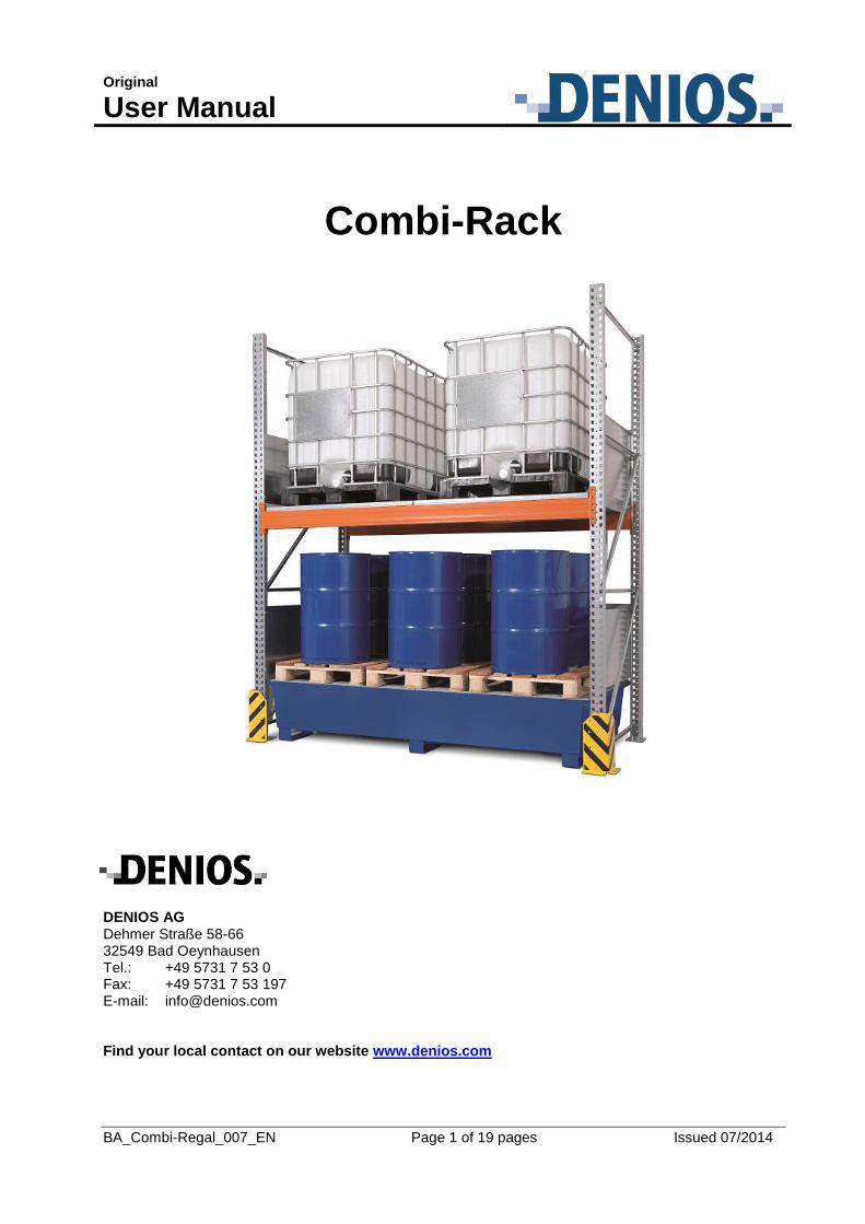
Combi-Rack
DENIOS AG Dehmer Straße 58-66 32549 Bad Oeynhausen Tel.: +49 5731 7 53 0 Fax: +49 5731 7 53 197 E-mail: [email protected]
Find your local contact on our website www.denios.com
BA_Combi-Regal_007_EN Page 2 of 22 pages Issued 07/2014
Index
1. General Instructions ..................................................................................................................................3
1.1. Key and explanation of symbols .........................................................................................................3
2. Basic Safety Instructions ...........................................................................................................................4
3. Safety regulations ......................................................................................................................................5
4. Intended use of the equipment ..................................................................................................................6
5. Product description ....................................................................................................................................7
5.1 Design ..................................................................................................................................................7 5.2 Construction .........................................................................................................................................7 5.3 Component overview (Types S-I and K-I)............................................................................................8 5.4. Technical Data ....................................................................................................................................9
6. Set-up / Commissioning ......................................................................................................................... 10
6.1 Conditions for placement .................................................................................................................. 10 6.2 Tooling required ................................................................................................................................ 12 6.3 Assembly .......................................................................................................................................... 13
6.3.1 Screw assembly framework ........................................................................................................................ 13 6.3.2 Rack construction ....................................................................................................................................... 15 6.3.3 Inserting the rails ....................................................................................................................................... 16 6.3.4 X bracing (Type 3 K6-I; 3 K2-I) ................................................................................................................. 17 6.3.5 Ground anchoring ...................................................................................................................................... 18
6.4 Parts list ............................................................................................................................................ 19 6.5 Earthing ............................................................................................................................................. 20
7. Operation ................................................................................................................................................ 20
8. Maintenance and repair .......................................................................................................................... 20
9. Removal from service ............................................................................................................................. 21
10. Disposal ................................................................................................................................................ 21
BA_Combi-Regal_007_EN Page 3 of 22 pages Issued 07/2014
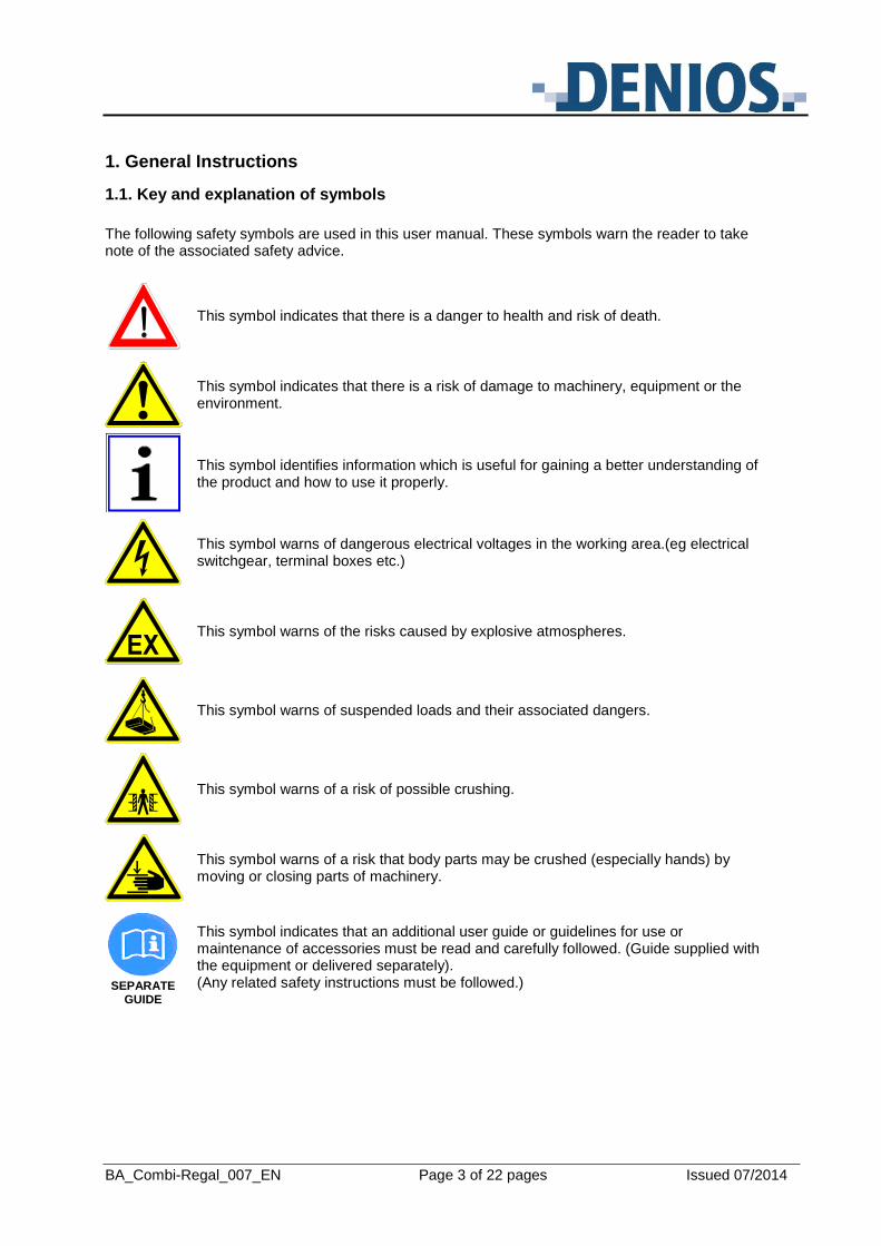
1. General Instructions
1.1. Key and explanation of symbols
The following safety symbols are used in this user manual. These symbols warn the reader to take note of the associated safety advice.
This symbol indicates that there is a danger to health and risk of death.
This symbol indicates that there is a risk of damage to machinery, equipment or the environment.
This symbol identifies information which is useful for gaining a better understanding of the product and how to use it properly.
This symbol warns of dangerous electrical voltages in the working area.(eg electrical switchgear, terminal boxes etc.)
This symbol warns of the risks caused by explosive atmospheres.
This symbol warns of suspended loads and their associated dangers.
This symbol warns of a risk of possible crushing.
This symbol warns of a risk that body parts may be crushed (especially hands) by moving or closing parts of machinery.
SEPARATE
GUIDE
This symbol indicates that an additional user guide or guidelines for use or maintenance of accessories must be read and carefully followed. (Guide supplied with the equipment or delivered separately). (Any related safety instructions must be followed.)
BA_Combi-Regal_007_EN Page 4 of 22 pages Issued 07/2014
2. Basic Safety Instructions
Keep this user manual in a safe place. It is intended to be used in a practical way and should be available to the user in the place where the equipment is used. This user manual applies to the Combi-Rack. It contains all the information needed regarding correct set-up, trouble-free operation, maintenance, removal from service and disposal. The instructions in this user manual must be carefully followed and adhered to. All those involved in the installation, operation, maintenance and repair of the product must have read and understood this user manual and have been trained and instructed in its use. These instructions for use do not absolve the operator from the duty to carry out special operational training in accordance with GefStoffV and BetrSichV. Operational training must be based on the safety datasheets for the substances to be stored and the risk assessment which must be carried out. The following information should also be considered in the operational training: - Type of storage (active/passive) - Load capacity of storage system - Guidelines for loading/unloading - Stored materials - Material properties - Combined storage prohibition Combined storage prohibition for certain substances must be observed. No changes, extensions or modifications may be made to the product without the manufacturer's written authorisation. National directives and safety regulations must be complied with.
BA_Combi-Regal_007_EN Page 5 of 22 pages Issued 07/2014
3. Safety regulations
The following safety regulations are in part extracts from the BG regulations for storage equipment and equipment in BG 234 (previously ZH 1/428) from the professional association.
1. When planning a racking system the "Guidelines for storage systems and equipment BGR 234" from the German Federation of Institutions for Statutory Accident Insurance and Prevention (Hauptverband der gewerblichen Berufsgenossenschaften), as well as the relevant workshop regulations and the general accident prevention guidelines must be observed.
2. Racking must be installed vertically. Shelf deviation from the vertical in the longitudinal
direction must not exceed 1/500 of the rack height and in the depth direction it must not exceed 1/400 of the rack height. Deviation from horizontal must not exceed 1/350 of the bay width. Deviations must be corrected using spacers.
3. Any unevenness in the floor must be compensated for with levelling plates.
4. For corrosively active industrial flooring (eg magnesite flooring) the support feet of the rack
must be insulated. The instructions for use from the flooring manufacturer must be observed.
5. Roadways within racking areas must be laid out so they are a minimum of 1.25m wide and side routes must be at least 0.75 m wide. The safety distance to transport vehicles must be a minimum of 0.50 m on each side.
6. Racking may only be loaded in accordance with its basic dimensional limitations. Loading of
shelves must be carried out evenly, as the static design requires an evenly distributed load. Pointed impact loads and sliding loads must therefore be avoided.
7. Shelving with a shelf load of over 200 kg or a bay load of over 1000 kg must be identified with
an identification plate. Identification plate details: Manufacturer, year of manufacture or order number, permitted shelf and bay loads. The identification plate supplied must be placed in a clearly visible location.
8. The given maximum load capacity of shelves and bays must not be exceeded.
9. The maximum support loadings and bearing pressures on the floor are set by DENIOS AG.
As the user, you must therefore ensure that this floor loading can be safely borne by the location where the racking is installed. If this information is not available, DENIOS AG may assume a permitted bearing pressure of 50 kg/cm² minimum.
10. The storage rack may only be set up or moved when it is unloaded.
11. Do not allow people to stand on racking framework or bays, especially shelving components.
12. Damaged or bent load-bearing components of a storage system must be immediately
replaced, as DENIOS AG only guarantees the system's load capacity when in perfect condition.
13. In accordance with section 10 Testing of work equipment, the racking system must be
inspected in accordance with equipment and product safety legislation.
BA_Combi-Regal_007_EN Page 6 of 22 pages Issued 07/2014
4. Intended use of the equipment
The Combi Rack is a storage system for the storage of hazardous substances and flammable liquids in GHS classes H 224, H 225 and H 226, in accordance with the hazardous substances regulations.
Only store substances to which the material of the spill pallet is resistant. See General User Manual
The permitted total volume of the storage system must not be exceeded.
The load capacity for the storage system stated on the datasheet / identification plate must be observed.
Ensure that stored substances are only stored on the grids.
The permitted total storage volume and the maximum permitted storage volume of the largest stored container must be observed in relation to the useful volume of the spill pallet.
Drums must be loaded onto the storage system or removed or brought down from it with suitable equipment (eg drum grippers).
Separated storage of substances is required. Store materials so that all containers and the spill pallet are visible.
Substances may only be stored together when a risk assessment has shown that there is no risk of possible reactions or physical interference.
Packaging and containers must meet the transport regulations.
Note: When using the storage system in Ex zones, ensure the components are sufficiently earthed
and check the conductivity of the components.
BA_Combi-Regal_007_EN Page 7 of 22 pages Issued 07/2014
5. Product description
5.1 Design
- For the storage of water-polluting substances and flammable liquids (H224-226) - Multi-functional storage system with modular design - Racking frame galvanized, rails powder coated, red-orange (RAL 2001) - Spill pallet either painted or galvanised (depending on design) - Can be combined and extended as required - Base plates for ground anchoring - Delivered flat-pack, with instructions for assembly
5.2 Construction
The Combi Rack is constructed as follows, depending on type: Type S, for storage of standing drums
- Spill pallet either painted or galvanized - Optional spill pallet inlay in plastic (PE HD), not electrically conductive - Storage surface with galvanised grids - Galvanised spill guards on 3 sides Type S, for storage of horizontal drums
- Spill pallet either painted or galvanized - Optional spill pallet inlay in plastic (PE HD), not electrically conductive - Storage surface with hot-dip galvanised drum supports Type K, for storage of IBCs
- Spill pallet either painted or galvanized - Optional spill pallet inlay in plastic (PE HD), not electrically conductive - Storage surface with galvanised grids - Galvanised spill guards on 3 sides
BA_Combi-Regal_007_EN Page 8 of 22 pages Issued 07/2014
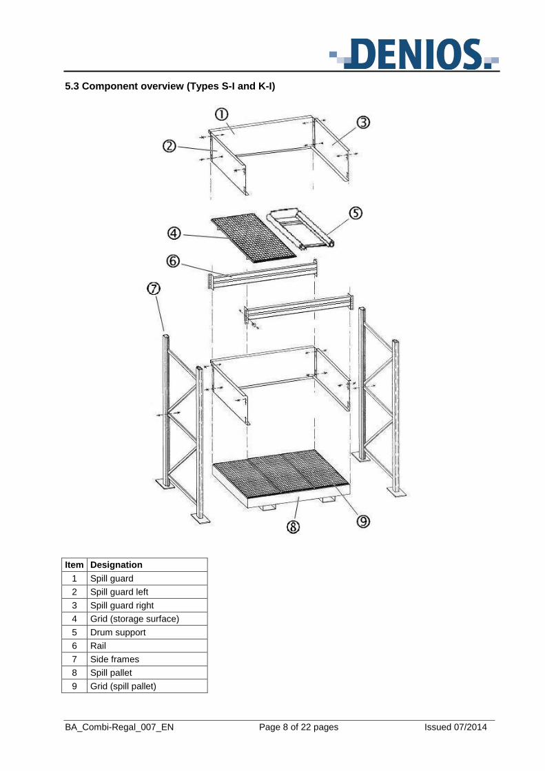
5.3 Component overview (Types S-I and K-I)
Item Designation
1 Spill guard
2 Spill guard left
3 Spill guard right
4 Grid (storage surface)
5 Drum support
6 Rail
7 Side frames
8 Spill pallet
9 Grid (spill pallet)
BA_Combi-Regal_007_EN Page 9 of 22 pages Issued 07/2014
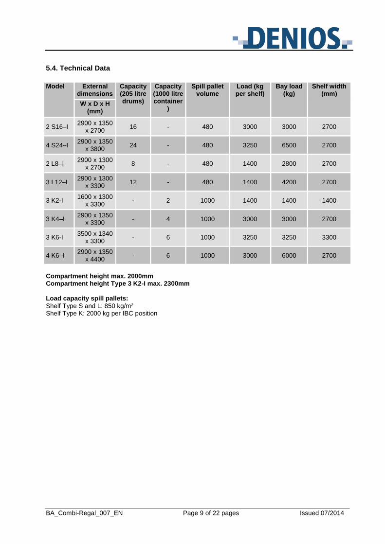
5.4. Technical Data
Model External dimensions
Capacity (205 litre drums)
Capacity (1000 litre container
)
Spill pallet volume
Load (kg per shelf)
Bay load (kg)
Shelf width (mm)
W x D x H (mm)
2 S16–I 2900 x 1350
x 2700 16 - 480 3000 3000 2700
4 S24–I 2900 x 1350
x 3800 24 - 480 3250 6500 2700
2 L8–I 2900 x 1300
x 2700 8 - 480 1400 2800 2700
3 L12–I 2900 x 1300
x 3300 12 - 480 1400 4200 2700
3 K2-I 1600 x 1300
x 3300 - 2 1000 1400 1400 1400
3 K4–I 2900 x 1350
x 3300 - 4 1000 3000 3000 2700
3 K6-I 3500 x 1340
x 3300 - 6 1000 3250 3250 3300
4 K6–I 2900 x 1350
x 4400 - 6 1000 3000 6000 2700
Compartment height max. 2000mm Compartment height Type 3 K2-I max. 2300mm Load capacity spill pallets: Shelf Type S and L: 850 kg/m² Shelf Type K: 2000 kg per IBC position
BA_Combi-Regal_007_EN Page 10 of 22 pages Issued 07/2014
6. Set-up / Commissioning
6.1 Conditions for placement
The Combi Rack must only be assembled on even, firm surfaces.
All racking must be anchored to the ground.
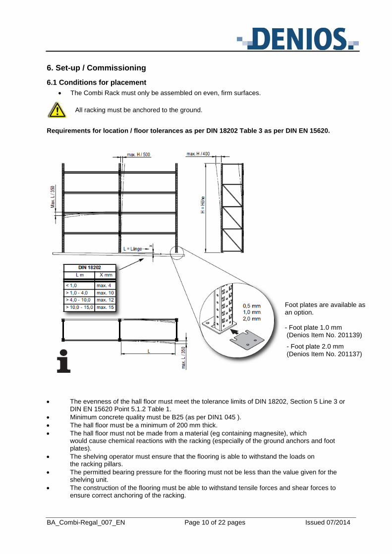
Requirements for location / floor tolerances as per DIN 18202 Table 3 as per DIN EN 15620.
The evenness of the hall floor must meet the tolerance limits of DIN 18202, Section 5 Line 3 or DIN EN 15620 Point 5.1.2 Table 1.
Minimum concrete quality must be B25 (as per DIN1 045 ).
The hall floor must be a minimum of 200 mm thick.
The hall floor must not be made from a material (eg containing magnesite), which would cause chemical reactions with the racking (especially of the ground anchors and foot plates).
The shelving operator must ensure that the flooring is able to withstand the loads on the racking pillars.
The permitted bearing pressure for the flooring must not be less than the value given for the shelving unit.
The construction of the flooring must be able to withstand tensile forces and shear forces to ensure correct anchoring of the racking.
Foot plates are available as an option. - Foot plate 1.0 mm (Denios Item No. 201139)
- Foot plate 2.0 mm (Denios Item No. 201137)
BA_Combi-Regal_007_EN Page 11 of 22 pages Issued 07/2014
Assembling Type S-I and K-I (standing / horizontal drum storage and KTC storage)
At least 2 people are needed to assemble the racking system. A waist high table or two free standing supports on which the components can be laid for pre-assembly would be of use.
When assembling the individual components, do not use brute force by striking with a metal hammer or using a levering rod. A rubber mallet or a soft wooden spacer should be used.
When assembling the frames take care not to overtighten the bolts. The bolts should be hand tightened first, then tightened using a spanner by 1 or 2 turns.
- Horizontal assembly of the side frames (see 6.3.1 / 6.3.2). - Set up two frames with a rail in between. - Slot in the lower pair of rails at the required bay height and secure in place with the rubber mallet. - Fit two safety pins per rail (see 6.3.3). - The distance between the top storage level and the end of the side frame must
be at least 500 mm. - Side frame diagonal measurements must be the same. - If necessary, straighten and align side frames. - Fit the spill pallet between the side frames and centre it. - Ensure there is the same gap at each side of the spill pallet. - Set the grids or drum supports on the rails. - Fit the right hand and rear spill guards on the grid and screw together. - Fit the left hand spill guard on the grid and secure to the rear spill guard. - Secure the rear panel to the side panels with nuts and bolts. - Set the spill guards on the grid and secure in the holes provided on the side frame. The side panels are
secured to the side frames with self tapping screws. - For Types 3 K6-I and 3 K2-I fit the x bracing (see 6.3.4). - Secure the side frames (see 6.3.5).
BA_Combi-Regal_007_EN Page 12 of 22 pages Issued 07/2014
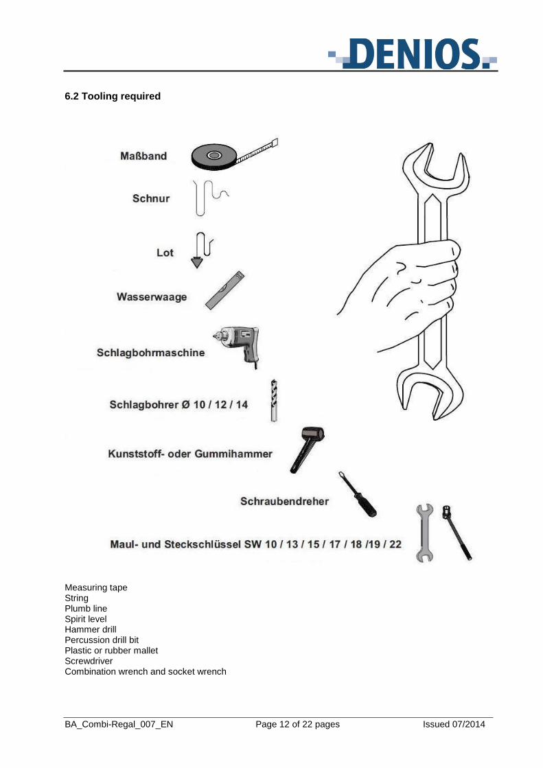
6.2 Tooling required
Measuring tape String Plumb line Spirit level Hammer drill Percussion drill bit Plastic or rubber mallet Screwdriver Combination wrench and socket wrench
BA_Combi-Regal_007_EN Page 13 of 22 pages Issued 07/2014
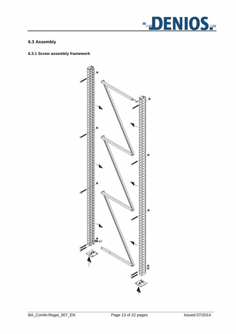
6.3 Assembly
6.3.1 Screw assembly framework
BA_Combi-Regal_007_EN Page 14 of 22 pages Issued 07/2014
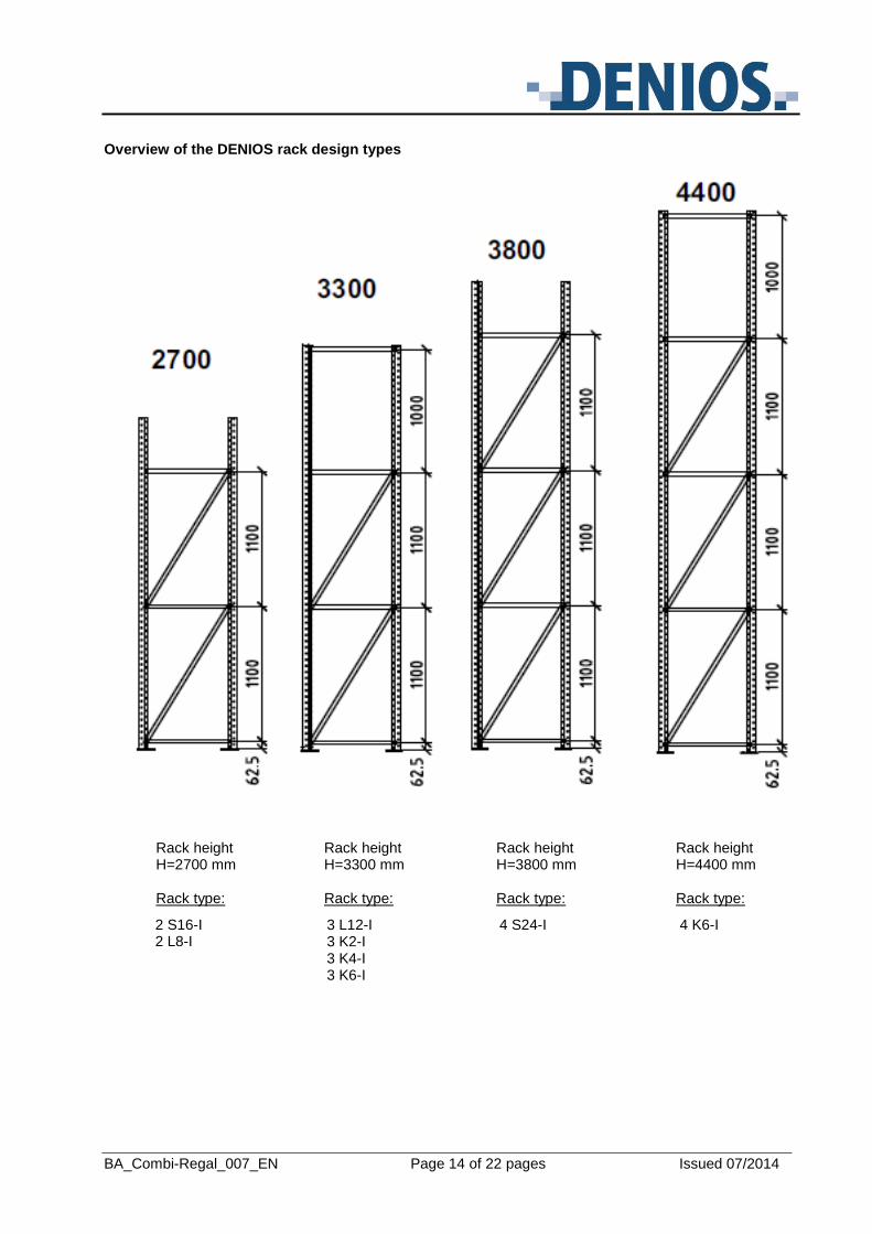
Overview of the DENIOS rack design types
Rack height Rack height Rack height Rack height H=2700 mm H=3300 mm H=3800 mm H=4400 mm
Rack type: Rack type: Rack type: Rack type:
2 S16-I 2 L8-I
4 S24-I 4 K6-I 3 L12-I 3 K2-I 3 K4-I 3 K6-I
BA_Combi-Regal_007_EN Page 15 of 22 pages Issued 07/2014
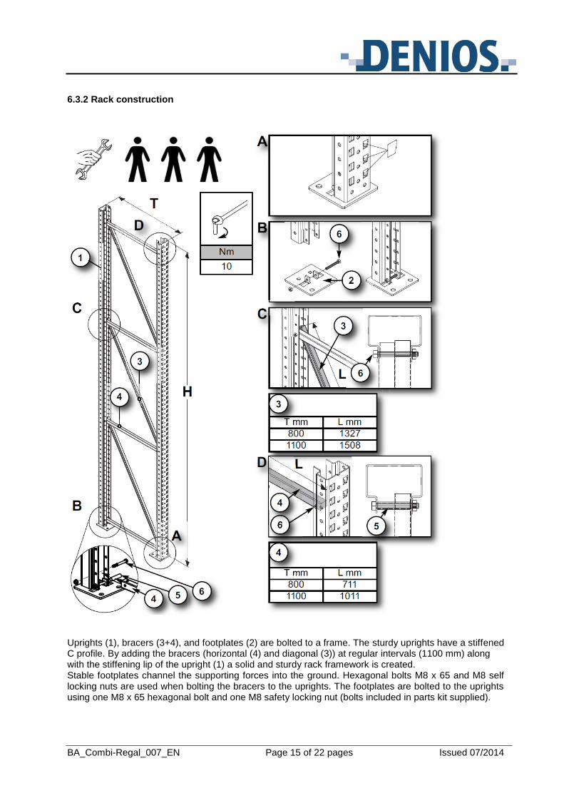
6.3.2 Rack construction
Uprights (1), bracers (3+4), and footplates (2) are bolted to a frame. The sturdy uprights have a stiffened C profile. By adding the bracers (horizontal (4) and diagonal (3)) at regular intervals (1100 mm) along with the stiffening lip of the upright (1) a solid and sturdy rack framework is created. Stable footplates channel the supporting forces into the ground. Hexagonal bolts M8 x 65 and M8 self locking nuts are used when bolting the bracers to the uprights. The footplates are bolted to the uprights using one M8 x 65 hexagonal bolt and one M8 safety locking nut (bolts included in parts kit supplied).
BA_Combi-Regal_007_EN Page 16 of 22 pages Issued 07/2014
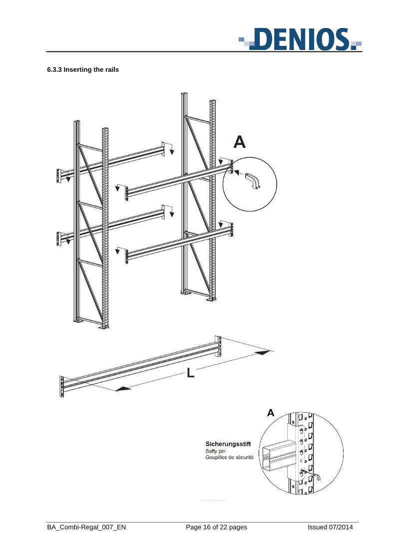
6.3.3 Inserting the rails
BA_Combi-Regal_007_EN Page 17 of 22 pages Issued 07/2014
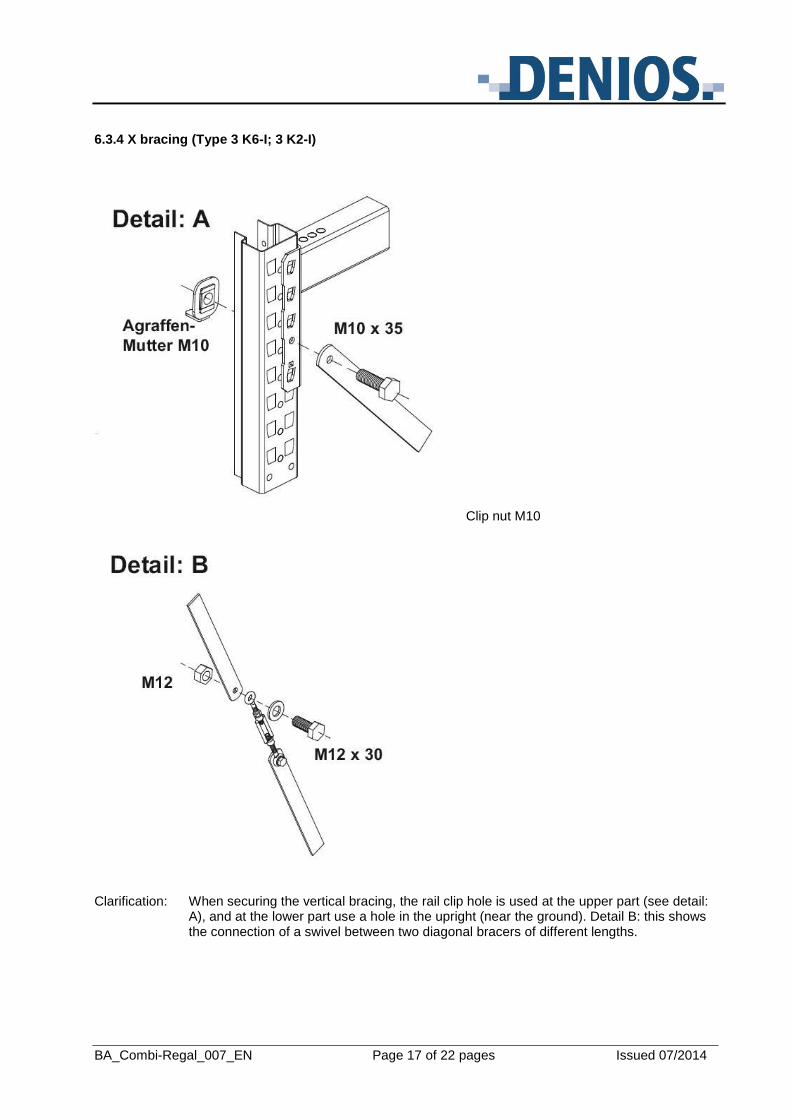
6.3.4 X bracing (Type 3 K6-I; 3 K2-I)
Clip nut M10
Clarification: When securing the vertical bracing, the rail clip hole is used at the upper part (see detail:
A), and at the lower part use a hole in the upright (near the ground). Detail B: this shows the connection of a swivel between two diagonal bracers of different lengths.
BA_Combi-Regal_007_EN Page 18 of 22 pages Issued 07/2014
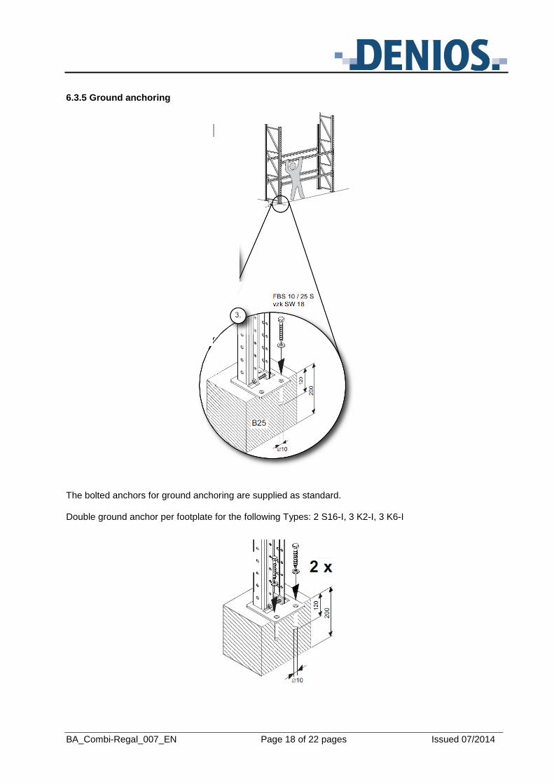
6.3.5 Ground anchoring
The bolted anchors for ground anchoring are supplied as standard. Double ground anchor per footplate for the following Types: 2 S16-I, 3 K2-I, 3 K6-I
BA_Combi-Regal_007_EN Page 19 of 22 pages Issued 07/2014
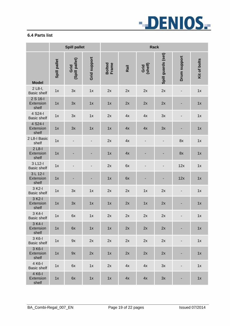
6.4 Parts list
Spill pallet Rack
Model
Sp
ill p
allet
Gri
d
(Sp
ill p
all
et)
Gri
d s
up
po
rt
Bo
lted
Fra
me
Rail
Gri
d
(sh
elf
)
Sp
ill g
ua
rds (
set)
Dru
m s
up
po
rt
Kit
of
bo
lts
2 L8-I, Basic shelf
1x 3x 1x 2x 2x 2x 2x - 1x
2 S 16-I Extension
shelf 1x 3x 1x 1x 2x 2x 2x - 1x
4 S24-I Basic shelf
1x 3x 1x 2x 4x 4x 3x - 1x
4 S24-I Extension
shelf 1x 3x 1x 1x 4x 4x 3x - 1x
2 L8-I Basic shelf
1x - - 2x 4x - - 8x 1x
2 L8-I Extension
shelf 1x - - 1x 4x - - 8x 1x
3 L12-I Basic shelf
1x - - 2x 6x - - 12x 1x
3 L 12-I Extension
shelf 1x - - 1x 6x - - 12x 1x
3 K2-I Basic shelf
1x 3x 1x 2x 2x 1x 2x - 1x
3 K2-I Extension
shelf 1x 3x 1x 1x 2x 1x 2x - 1x
3 K4-I Basic shelf
1x 6x 1x 2x 2x 2x 2x - 1x
3 K4-I Extension
shelf 1x 6x 1x 1x 2x 2x 2x - 1x
3 K6-I Basic shelf
1x 9x 2x 2x 2x 2x 2x - 1x
3 K6-I Extension
shelf 1x 9x 2x 1x 2x 2x 2x - 1x
4 K6-I Basic shelf
1x 6x 1x 2x 4x 4x 3x - 1x
4 K6-I Extension
shelf 1x 6x 1x 1x 4x 4x 3x - 1x
BA_Combi-Regal_007_EN Page 20 of 22 pages Issued 07/2014
6.5 Earthing
Combi Racks must be earthed if flammable substances are being stored.
7. Operation
Using a suitable lifting device (eg forklift with drum tongs) carefully place or remove the containers on the grids.
When storing metallic containers place these carefully on the grid (speed ≤ 1m/s) to prevent any possible sparks.
Take note of the bay depth when loading or unloading containers.
No unauthorised access to the Combi Rack is permitted.
Do not use without safety pins.
Containers must be stored so that the spill pallet remains visible from one position at all times.
Note safety regulations!
8. Maintenance and repair
When replacing parts use only original replacement parts from the manufacturer!
The following table contains information on maintenance.
Part Action inspection
Spill pallet inspect for any leaked liquids once per week
Spill pallet check, record every 2 years
Grid check once per year
Grid mounting check once per year
Shelving system check, especially hooked connections, bolted connections and safety pins
once per year
Shelving system refinish surface protection once per year
Repair any faults immediately (screws, damage to paintwork, deformation and general damage)
BA_Combi-Regal_007_EN Page 21 of 22 pages Issued 07/2014
9. Removal from service
In the case of damage, decommission the storage system and label accordingly.
10. Disposal
The Combi Rack comprises different components and parts which must be disposed of or recycled according to local and legal regulations.
Clean the rack components thoroughly before disposal to remove any hazardous material residue.
Dismantle or disassemble the individual components of the rack and arrange the components into the following groups:
Steel
Light metals
Non-ferrous metals
Plastic
Process the separated components through approved disposal and recycling channels.
BA_Combi-Regal_007_EN Page 22 of 22 pages Issued 07/2014


![COLOMBO COMBI STEAM OVEN - 20 Pan · combi steam oven piron [colombo & marco polo] - s/steel stand combi steam oven - 10 pan colombo cop2110 combi steam oven piron [colombo] - 10](https://img.pdfslide.us/doc/110x75/606dfc29b21fab25963f6e5a/colombo-combi-steam-oven-20-pan-combi-steam-oven-piron-colombo-marco-polo.jpg)