Embed Size (px)
Citation preview
Combating green oil formation in a CCR reformer
CCR reformer units need chloride injection during regeneration to promote platinum dispersion and to restore catalyst acidity.
This leads to hydrogen chloride formation, and a highly viscous green oil may also be formed at some locations in the unit. This is one of the main reasons why the operation of a CCR reformer’s rich gas compressors can affect unit reliability. This article looks at a real-world example of green oil formation, and shows how the main cause was identified and then overcome.
When looking for a high rate of unit utilisation in a refinery, the availability and reliability of all equipment is of utmost importance to prevent loss of production and negative effects on profit-ability. So a refiner should either perform proper maintenance or find a way to deal with any kind of problem that threatens unit reliability.
Catalyst deactivation It has been known for many years that acid gases are present in the petroleum industries in liquid or gas streams. These gases include hydro-gen halides such as HCl, HF, HBr, HI and mixtures thereof. From an acid gas point of view, one of the key processes of the petroleum industry are reforming reactions such as those in CCR reformer units. In the catalytic reforming process, sweet heavy naphtha is processed in contact with a platinium-based catalyst to produce a high-octane product. Hydrogen is a byproduct of the catalytic reforming process and some of this product is recycled to the reaction section to maintain catalyst stability. This reforming catalyst is promoted with chloride in
Osman Kubilay Karan, Mehmet Asim Ay and Koray Kahraman Tüpras Kirikkale RefineryArnaud Selmen Axens Technology &Technical Services
the presence of water, resulting in the produc-tion of hydrogen chloride. Thus, the gas that is not recycled but sent to downstream catalytic processes and known as net gas contains hydro-gen chloride. As a result, this chloride-containing gas can deactivate downstream catalysis because it can poison catalysts and cause undesired reactions.
Even the presence of a small amount of HCl in the net hydrogen gas can seriously interfere with the operation of downstream processes that use hydrogen. It can also cause corrosion problems in equipment such as pipes, valves and compres-sors. In addition, the formation of polymerised long-chain hydrocarbons, generally called green oils, is a common problem in CCR reformer units.
Green oils are actually the end products of undesirable polymerisation reactions taking place over the catalyst surface area, in which the reac-tion of HCl with hydrocarbons leads to chlorinated hydrocarbons. The presence of HCl will promote olefin polymerisation reactions with green oil downstream of the reaction section. These reactions are mainly chemical combina-tions of relatively small molecules with huge chain-like or network-structured molecules. Polymerised molecules formed in this fashion have complex multi-chain chemistries and high boiling points, and are typically waxy in nature. These molecules are green or red in colour and contain mainly C6-C18 hydrocarbons, with a poten-tial tail above C40, and are believed to be oligomers of light olefinic hydrocarbons, with some aromatic nuclei included in the structures. HCl in gas or liquid hydrocarbon streams must be
www.digitalrefining.com/article/1000853 PTQ Q3 2013 1
The addition of a chloride adsorber guard bed solved a refiner’s issues with contamination affecting a CCR reformer’s rich gas compressor
removed, since it may cause undesired catalytic reactions and poison the catalyst systems of the downstream units. Moreover, HCl is considered a hazardous material, so the release of this substance to the environment must be avoided.
Chlorine sourceFor the time being, the exact mechanism of green oil formation is unknown, but it is believed that it is formed by the catalytic reaction of HCl with hydrocarbons, which leads to chlorinated hydrocarbons. Classically, a chlorination agent is injected during catalyst regeneration in the oxychlorination part of the regenerator to restore the optimal metallic phase dispersion of the platinum-based catalyst and to restore a normal chlorine content of 0.9-1.1 wt% on the catalyst. This leads typically to a recycle gas chlorine content of 1 ppmwt with a water content of less than 30 ppm. The HCl content of the recycle gas is kept under control, but hydrogen gas from the
2 PTQ Q3 2013 www.digitalrefining.com/article/1000853
reduction section is also a chlorine source and both streams enter the net gas booster compres-sor section. The main chlorine contributor in the net gas comes from the reduction gas, which leads to exacerbated issues of green oil formation.
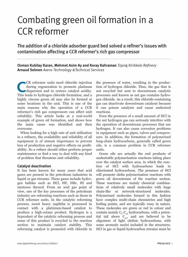
Tüpra s Kirikkale refinery’s CCR reformer unit is licensed by Axens and was put into operation in 2008. The basic flow scheme is shown in Figure 1. Shortly after unit startup, the CCR reformer’s H2-rich gas compressor was encoun-tering frequent emergency shutdowns. These shutdowns were initiated by serious vibrations threatening the operation and reliability of the compressor. When it was dismantled for investi-gation, some deposits were found (see Figures 2a-e).
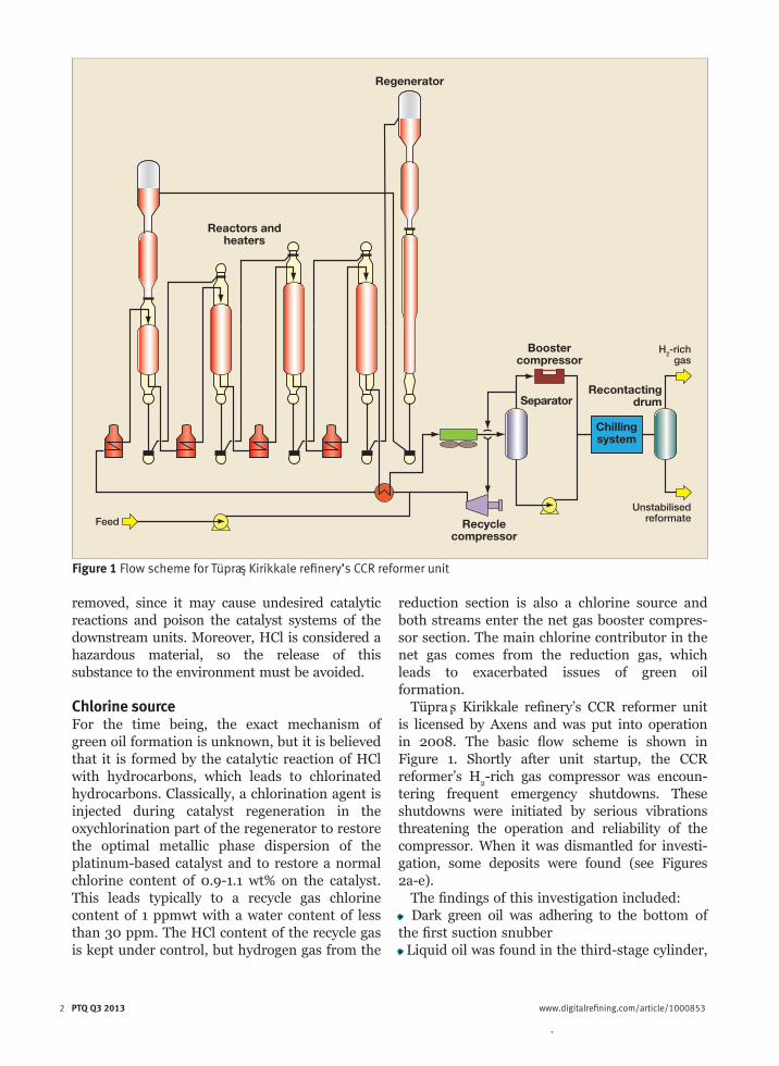
The findings of this investigation included:• Dark green oil was adhering to the bottom of the first suction snubber• Liquid oil was found in the third-stage cylinder,
Feed
H2-rich gas
Unstabilised reformate
Chilling system
Reactors and heaters
Regenerator
Recycle compressor
Booster compressor
Recontacting drumSeparator
Figure 1 Flow scheme for Tüpras Kirikkale refinery’s CCR reformer unit
2 PTQ Q3 2013 www.digitalrefining.com/article/1000853
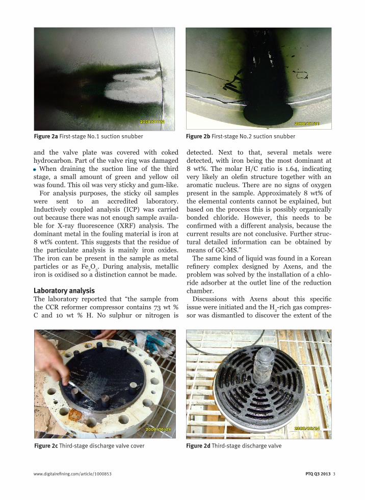
and the valve plate was covered with coked hydrocarbon. Part of the valve ring was damaged• When draining the suction line of the third stage, a small amount of green and yellow oil was found. This oil was very sticky and gum-like.
For analysis purposes, the sticky oil samples were sent to an accredited laboratory. Inductively coupled analysis (ICP) was carried out because there was not enough sample availa-ble for X-ray fluorescence (XRF) analysis. The dominant metal in the fouling material is iron at 8 wt% content. This suggests that the residue of the particulate analysis is mainly iron oxides. The iron can be present in the sample as metal particles or as Fe2O3. During analysis, metallic iron is oxidised so a distinction cannot be made.
Laboratory analysisThe laboratory reported that “the sample from the CCR reformer compressor contains 73 wt % C and 10 wt % H. No sulphur or nitrogen is
www.digitalrefining.com/article/1000853 PTQ Q3 2013 3
detected. Next to that, several metals were detected, with iron being the most dominant at 8 wt%. The molar H/C ratio is 1.64, indicating very likely an olefin structure together with an aromatic nucleus. There are no signs of oxygen present in the sample. Approximately 8 wt% of the elemental contents cannot be explained, but based on the process this is possibly organically bonded chloride. However, this needs to be confirmed with a different analysis, because the current results are not conclusive. Further struc-tural detailed information can be obtained by means of GC-MS.”
The same kind of liquid was found in a Korean refinery complex designed by Axens, and the problem was solved by the installation of a chlo-ride adsorber at the outlet line of the reduction chamber.
Discussions with Axens about this specific issue were initiated and the H2-rich gas compres-sor was dismantled to discover the extent of the
Figure 1 Flow scheme for Tüpras Kirikkale refinery’s CCR reformer unit
Figure 2a First-stage No.1 suction snubber Figure 2b First-stage No.2 suction snubber
Figure 2c Third-stage discharge valve cover Figure 2d Third-stage discharge valve
deposit. Finally, an adsorber drum was recom-mended, and an action plan has been defined to implement a chloride guard bed on the hydrogen gas from the reduction chamber.
It is clear that green oil formation is highly dependent on the chlorine content of the H2-rich gas handled by the rich gas compressor. In addi-tion, hydrogen gas used for catalyst reduction is the main contributor of chloride. Besides good chloride management, the strategy to tackle this issue was to remove chloride from this process stream by means of a specific adsorbent before the suction section of the compressor.
Axens carried out the design of the hydrogen chloride guard bed to be implemented at the outlet line of the reduction chamber. A non-re-generative promoted alumina was selected for the removal of HCl in the gas phase. A simple flow sheet for the scheme is shown in Figure 3.
Alumina-based adsorbent is widely used in the petroleum refining industry as a trapping mate-rial for various impurities. Some special
formulations loaded in a fixed-bed vessel enable the removal of small quantities of chloride in liquid or gas streams. The adsorbent used for this process is generally disposed of at the end of its useful life; in other words, it is not regenera-ble. As the alumina-based adsorbents pick up HCl, the sodium or calcium promotor, as well as aluminium, reacts with HCl to form chloride salts. Green oil may also be formed in adsorp-tion beds, and when these green oils are formed in fixed-bed adsorbents they cause fouling and result in the premature failure of the sorbent, which can be understood by a delta P increase through the bed.
Dräger tube chloride analyses are a simple way to check on a weekly basis the adsorbent’s performance and to check if there is any Cl breakthrough to determine adsorbent replace-ment time, reported to be typically more than one year.
This new arrangement to mitigate the problem was put on stream in January 2012. Weekly Dräger tube measurements are taken at the outlet stream of this adsorber and the results are 0 ppm HCl, whereas inlet concentration aver-ages 30 ppm HCl.
ConclusionCurrently, the H2-rich gas compressors are running smoothly without any problem. The compressors were recently opened by the mechanical maintenance group and no green oil formation was found, although they ran for almost one year without a major interruption, indicating that the vibration problem was correctly identified. This case shows that a good licensor and refinery relationship is essential for solving problems that require both technological and operational experience.
Osman Kubilay Karan is the Hydroprocessing Units Process Superintendent with Tüpras Kirikkale refinery. His 25 years of refinery experience includes the operational and process sides of crude, vacuum units, hydrocracker, hydrogen production plants, CCR and DHP units. He holds a degree in chemical engineering from Middle East Technical University, Turkey, and is a certified Energy Supervisor for industrial plants. Email: [email protected]
4 PTQ Q3 2013 www.digitalrefining.com/article/1000853
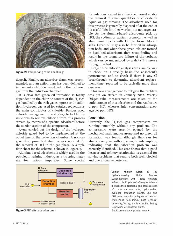
Figure 2e Rod packing carbon seal rings
Reduction chamber
Reaction section
Dedicated chlorine trap
Separator drum
H2 to reduction
H2 from reduction
To booster compressor
Recycle gas
Catalyst streamProcess stream
Figure 3 PFD after adsorber drum

Mehmet Asim Ay is CCR/NHT/ISOM Units Process Superintendent with Tüpras Kirikkale refinery. He holds a degree in chemical engineering from Middle East Technical University, Turkey. Email: [email protected] Kahraman is CCR/NHT/ISOM Units Process Chief Engineer with Tüpras Kirikkale refinery. His six years of refinery experience includes the process side of hydrocracker and hydrogen production plants, sulphur recovery, NHT, ISOM, CCR and DHP units. He holds a degree in chemical engineering from Middle East Technical University, Turkey. Email: [email protected] Selmen is Axens’ Technology Manager for Naphtha Hydrotreatment and Reforming Technologies. He has worked mainly with bottom-of the-barrel technologies, specialising in heavy crude oil upgrading. He has also been involved in the process design of aromatics complexes and NHT, as well
as reforming units startup and troubleshooting. He holds an engineering degree from the ENSGTI engineering school and a DEA in refinery process modelling from IFP School. Email: [email protected]
www.digitalrefining.com/article/1000853 PTQ Q3 2013 5 4 PTQ Q3 2013 www.digitalrefining.com/article/1000853
LINKS
More articles from: Axens
More articles from the following categories: Corrosion/Fouling Control Rotating Equipment


![Combating Trademark Counterfeiting on the Internetmedia.straffordpub.com/products/combating-trademark... · 2009. 9. 2. · August 19, 2009 [ 5 ] Combating Trademark Counterfeiting](https://img.pdfslide.us/doc/110x75/6041e9a9167fff75267182f4/combating-trademark-counterfeiting-on-the-2009-9-2-august-19-2009-5-combating.jpg)