Embed Size (px)
Citation preview
C H A P T E R
T1/E1 Controller Command
3
T1/E1 Controller Commands
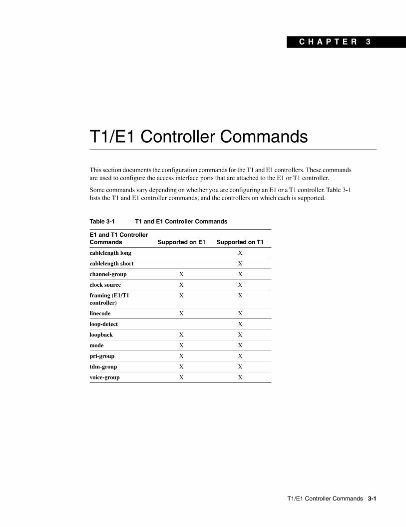
This section documents the configuration commands for the T1 and E1 controllers. These commands are used to configure the access interface ports that are attached to the E1 or T1 controller.
Some commands vary depending on whether you are configuring an E1 or a T1 controller. Table 3-1 lists the T1 and E1 controller commands, and the controllers on which each is supported.
Table 3-1 T1 and E1 Controller Commands
E1 and T1 Controller Commands Supported on E1 Supported on T1
cablelength long X
cablelength short X
channel-group X X
clock source X X
framing (E1/T1 controller)
X X
linecode X X
loop-detect X
loopback X X
mode X X
pri-group X X
tdm-group X X
voice-group X X
s 3-1
cablelength long
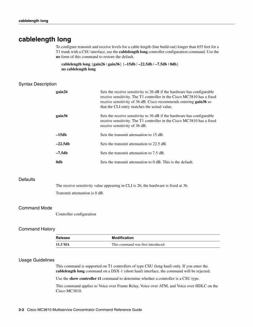
cablelength longTo configure transmit and receive levels for a cable length (line build-out) longer than 655 feet for a T1 trunk with a CSU interface, use the cablelength long controller configuration command. Use the no form of this command to restore the default.
cablelength long {gain26 | gain36} {–15db | –22.5db | –7.5db | 0db}no cablelength long
Syntax Description
DefaultsThe receive sensitivity value appearing in CLI is 26; the hardware is fixed at 36.
Transmit attenuation is 0 dB.
Command ModeController configuration
Command History
Usage GuidelinesThis command is supported on T1 controllers of type CSU (long haul) only. If you enter the cablelength long command on a DSX-1 (short haul) interface, the command will be rejected.
Use the show controller t1 command to determine whether a controller is a CSU type.
This command applies to Voice over Frame Relay, Voice over ATM, and Voice over HDLC on the Cisco MC3810.
gain26 Sets the receive sensitivity to 26 dB if the hardware has configurable receive sensitivity. The T1 controller in the Cisco MC3810 has a fixed receive sensitivity of 36 dB. Cisco recommends entering gain36 so that the CLI entry matches the actual value.
gain36 Sets the receive sensitivity to 36 dB if the hardware has configurable receive sensitivity. The T1 controller in the Cisco MC3810 has a fixed receive sensitivity of 36 dB.
–15db Sets the transmit attenuation to 15 dB.
–22.5db Sets the transmit attenuation to 22.5 dB.
–7.5db Sets the transmit attenuation to 7.5 dB.
0db Sets the transmit attenuation to 0 dB. This is the default.
Release Modification
11.3 MA This command was first introduced.
3-2 Cisco MC3810 Multiservice Concentrator Command Reference Guide
cablelength long
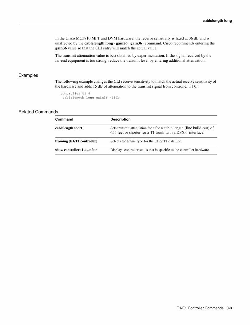
In the Cisco MC3810 MFT and DVM hardware, the receive sensitivity is fixed at 36 dB and is unaffected by the cablelength long {gain26 | gain36} command. Cisco recommends entering the gain36 value so that the CLI entry will match the actual value.
The transmit attenuation value is best obtained by experimentation. If the signal received by the far-end equipment is too strong, reduce the transmit level by entering additional attenuation.
ExamplesThe following example changes the CLI receive sensitivity to match the actual receive sensitivity of the hardware and adds 15 dB of attenuation to the transmit signal from controller T1 0:
controller T1 0cablelength long gain36 -15db
Related Commands
Command Description
cablelength short Sets transmit attenuation for a for a cable length (line build-out) of 655 feet or shorter for a T1 trunk with a DSX-1 interface.
framing (E1/T1 controller) Selects the frame type for the E1 or T1 data line.
show controller t1 number Displays controller status that is specific to the controller hardware.
T1/E1 Controller Commands 3-3
cablelength short
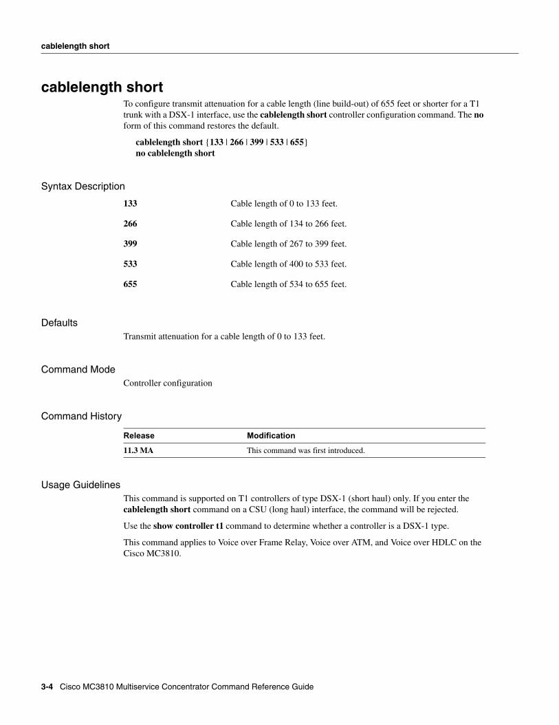
cablelength shortTo configure transmit attenuation for a cable length (line build-out) of 655 feet or shorter for a T1 trunk with a DSX-1 interface, use the cablelength short controller configuration command. The no form of this command restores the default.
cablelength short {133 | 266 | 399 | 533 | 655}no cablelength short
Syntax Description
DefaultsTransmit attenuation for a cable length of 0 to 133 feet.
Command ModeController configuration
Command History
Usage GuidelinesThis command is supported on T1 controllers of type DSX-1 (short haul) only. If you enter the cablelength short command on a CSU (long haul) interface, the command will be rejected.
Use the show controller t1 command to determine whether a controller is a DSX-1 type.
This command applies to Voice over Frame Relay, Voice over ATM, and Voice over HDLC on the Cisco MC3810.
133 Cable length of 0 to 133 feet.
266 Cable length of 134 to 266 feet.
399 Cable length of 267 to 399 feet.
533 Cable length of 400 to 533 feet.
655 Cable length of 534 to 655 feet.
Release Modification
11.3 MA This command was first introduced.
3-4 Cisco MC3810 Multiservice Concentrator Command Reference Guide
cablelength short
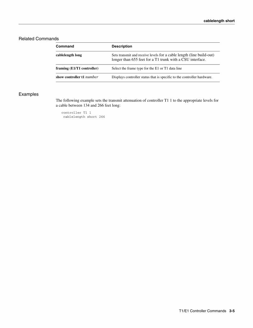
Related Commands
ExamplesThe following example sets the transmit attenuation of controller T1 1 to the appropriate levels for a cable between 134 and 266 feet long:
controller T1 1cablelength short 266
Command Description
cablelength long Sets transmit and receive levels for a cable length (line build-out) longer than 655 feet for a T1 trunk with a CSU interface.
framing (E1/T1 controller) Select the frame type for the E1 or T1 data line
show controller t1 number Displays controller status that is specific to the controller hardware.
T1/E1 Controller Commands 3-5

channel-group
channel-groupTo configure a list of timeslots for voice channels on controller T1 0 or E1 0, use the channel-group controller configuration command. Use the no form of this command to delete the channel group.
channel-group channel-no timeslots timeslot-list speed {56 | 64}no channel-group channel-no timeslots timeslot-list speed {56 | 64}
Syntax Description
Defaults64 kbps (for T1).64 kbps (for E1).
Command ModeController configuration
Command History
Usage GuidelinesThis command applies to the configuration of Voice over Frame Relay, Voice over ATM, and Voice over HDLC on the Cisco MC3810.
This command creates a logical interface, serial 0:channel (s0:x) on controller T1 0 or E1 0 (MFT).
Only one channel group can be configured on a controller.
Note Channel groups, voice groups, and TDM groups all use group numbers. All group numbers configured for channel groups, voice groups, and TDM groups must be unique on the local Cisco MC3810 concentrator. For example, you cannot use the same group number for a channel group and a TDM group.
channel-no ID number to identify the channel group. The valid range is 0 to 31.
Note For any of the timeslots within the timeslot range provided for the channel group, use timeslot -1 as the channel number.
timeslot list Timeslots (DS0s) to include in this channel group.The valid timeslots are: 1 to 24 for T1; 1 to 15 and 17 to 31 for E1.
speed {56 | 64} The speed of the underlying DS0s: 56 kbps, or 64 kbps.
If you specify 56 kbps, the channel group is limited to 14 channels on the Cisco MC3810 MFT. Because 56 is the default, you should specify 64 if you need more than 14 channels.
Release Modification
11.3 MA This command was first introduced.
3-6 Cisco MC3810 Multiservice Concentrator Command Reference Guide

channel-group
ExamplesThe following example configures a channel group on controller T1 0 on a Cisco MC3810:
controller T1 0channel-group 10 timeslots 10-24 speed 64
T1/E1 Controller Commands 3-7
clock source
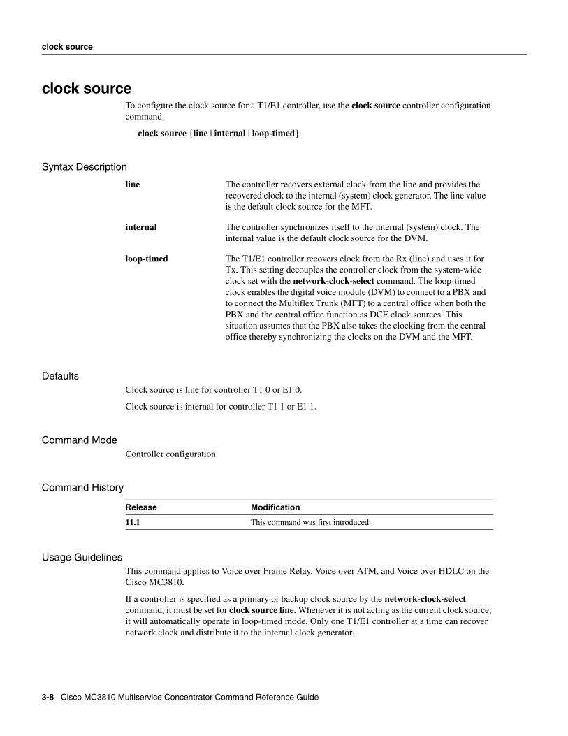
clock sourceTo configure the clock source for a T1/E1 controller, use the clock source controller configuration command.
clock source {line | internal | loop-timed}
Syntax Description
DefaultsClock source is line for controller T1 0 or E1 0.
Clock source is internal for controller T1 1 or E1 1.
Command ModeController configuration
Command History
Usage GuidelinesThis command applies to Voice over Frame Relay, Voice over ATM, and Voice over HDLC on the Cisco MC3810.
If a controller is specified as a primary or backup clock source by the network-clock-select command, it must be set for clock source line. Whenever it is not acting as the current clock source, it will automatically operate in loop-timed mode. Only one T1/E1 controller at a time can recover network clock and distribute it to the internal clock generator.
line The controller recovers external clock from the line and provides the recovered clock to the internal (system) clock generator. The line value is the default clock source for the MFT.
internal The controller synchronizes itself to the internal (system) clock. The internal value is the default clock source for the DVM.
loop-timed The T1/E1 controller recovers clock from the Rx (line) and uses it for Tx. This setting decouples the controller clock from the system-wide clock set with the network-clock-select command. The loop-timed clock enables the digital voice module (DVM) to connect to a PBX and to connect the Multiflex Trunk (MFT) to a central office when both the PBX and the central office function as DCE clock sources. This situation assumes that the PBX also takes the clocking from the central office thereby synchronizing the clocks on the DVM and the MFT.
Release Modification
11.1 This command was first introduced.
3-8 Cisco MC3810 Multiservice Concentrator Command Reference Guide
clock source
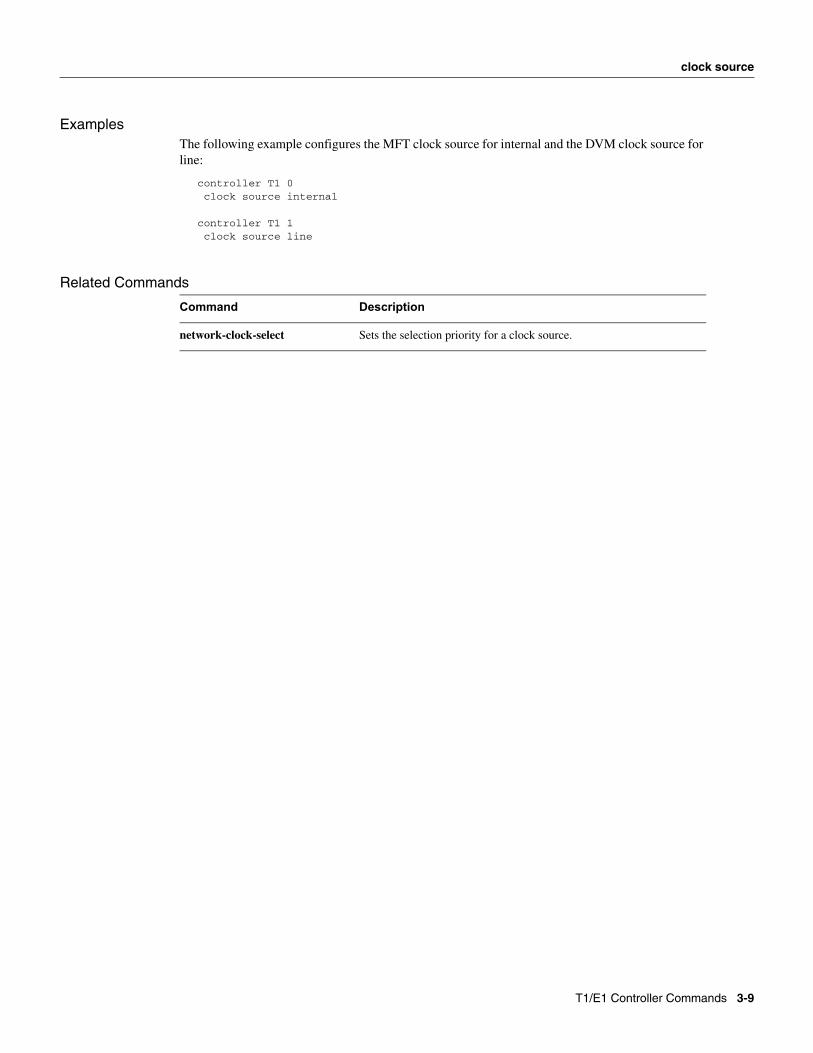
ExamplesThe following example configures the MFT clock source for internal and the DVM clock source for line:
controller T1 0 clock source internal
controller T1 1 clock source line
Related Commands
Command Description
network-clock-select Sets the selection priority for a clock source.
T1/E1 Controller Commands 3-9
framing (E1/T1 controller)
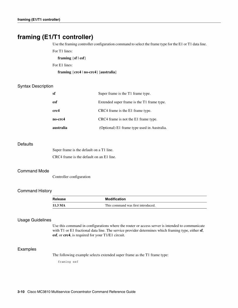
framing (E1/T1 controller)Use the framing controller configuration command to select the frame type for the E1 or T1 data line.
For T1 lines:
framing {sf | esf}
For E1 lines:
framing {crc4 | no-crc4} [australia]
Syntax Description
DefaultsSuper frame is the default on a T1 line.
CRC4 frame is the default on an E1 line.
Command ModeController configuration
Command History
Usage GuidelinesUse this command in configurations where the router or access server is intended to communicate with T1 or E1 fractional data line. The service provider determines which framing type, either sf, esf, or crc4, is required for your T1/E1 circuit.
ExamplesThe following example selects extended super frame as the T1 frame type:
framing esf
sf Super frame is the T1 frame type.
esf Extended super frame is the T1 frame type.
crc4 CRC4 frame is the E1 frame type.
no-crc4 CRC4 frame is not the E1 frame type.
australia (Optional) E1 frame type used in Australia.
Release Modification
11.3 MA This command was first introduced.
3-10 Cisco MC3810 Multiservice Concentrator Command Reference Guide
framing (E1/T1 controller)
Related Commands
Command Description
cablelength Sets the gain according to the length of the T1 or E1 line.
linecode Sets the line encoding method.
T1/E1 Controller Commands 3-11
linecode
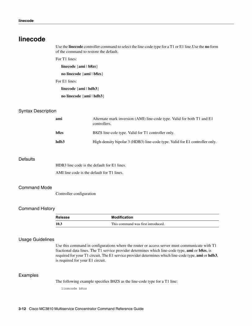
linecodeUse the linecode controller command to select the line-code type for a T1 or E1 line.Use the no form of the command to restore the default.
For T1 lines:
linecode {ami | b8zs}
no linecode {ami | b8zs}
For E1 lines:
linecode {ami | hdb3}
no linecode {ami | hdb3}
Syntax Description
DefaultsHDB3 line code is the default for E1 lines.
AMI line code is the default for T1 lines.
Command ModeController configuration
Command History
Usage GuidelinesUse this command in configurations where the router or access server must communicate with T1 fractional data lines. The T1 service provider determines which line-code type, ami or b8zs, is required for your T1 circuit. The E1 service provider determines which line-code type, ami or hdb3, is required for your E1 circuit.
ExamplesThe following example specifies B8ZS as the line-code type for a T1 line:
linecode b8zs
ami Alternate mark inversion (AMI) line-code type. Valid for both T1 and E1 controllers.
b8zs B8ZS line-cole type. Valid for T1 controller only.
hdb3 High-density bipolar 3 (HDB3) line-code type. Valid for E1 controller only.
Release Modification
10.3 This command was first introduced.
3-12 Cisco MC3810 Multiservice Concentrator Command Reference Guide

linecode
Related Commands
Command Description
cablelength Sets the gain according to the length of the T1 or E1 line.
framing (E1/T1 controller) Select the frame type for the E1 or T1 data line.
T1/E1 Controller Commands 3-13
loop-detect
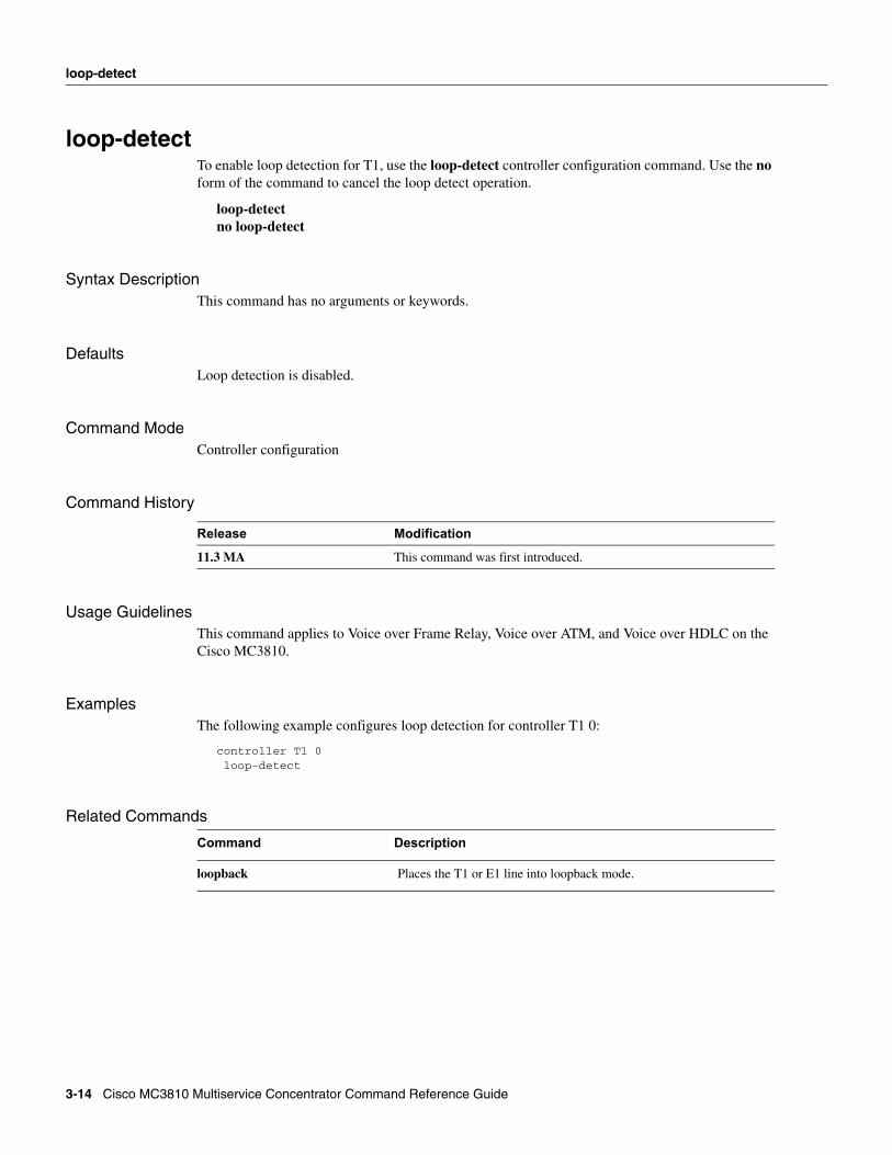
loop-detectTo enable loop detection for T1, use the loop-detect controller configuration command. Use the no form of the command to cancel the loop detect operation.
loop-detectno loop-detect
Syntax DescriptionThis command has no arguments or keywords.
DefaultsLoop detection is disabled.
Command ModeController configuration
Command History
Usage GuidelinesThis command applies to Voice over Frame Relay, Voice over ATM, and Voice over HDLC on the Cisco MC3810.
ExamplesThe following example configures loop detection for controller T1 0:
controller T1 0 loop-detect
Related Commands
Release Modification
11.3 MA This command was first introduced.
Command Description
loopback Places the T1 or E1 line into loopback mode.
3-14 Cisco MC3810 Multiservice Concentrator Command Reference Guide
loopback
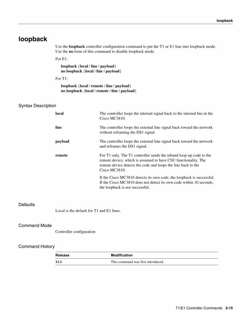
loopbackUse the loopback controller configuration command to put the T1 or E1 line into loopback mode. Use the no form of this command to disable loopback mode.
For E1:
loopback {local | line | payload}no loopback {local | line | payload}
For T1:
loopback {local | remote | line | payload}no loopback {local | remote | line | payload}
Syntax Description
DefaultsLocal is the default for T1 and E1 lines.
Command ModeController configuration
Command History
local The controller loops the internal signal back to the internal bus in the Cisco MC3810.
line The controller loops the external line signal back toward the network without reframing the DS1 signal.
payload The controller loops the external line signal back toward the network and reframes the DS1 signal.
remote For T1 only. The T1 controller sends the inband loop-up code to the remote device, which is assumed to have CSU functionality. The remote device detects the code and loops the line back to the Cisco MC3810.
If the Cisco MC3810 detects its own code, the loopback is successful. If the Cisco MC3810 does not detect its own code within 10 seconds, the loopback is not successful.
Release Modification
11.1 This command was first introduced.
T1/E1 Controller Commands 3-15
loopback
Usage GuidelinesThis command applies to Voice over Frame Relay, Voice over ATM, and Voice over HDLC on the Cisco MC3810.
ExamplesThe following example establishes a loopback of the incoming T1 signal on controller T1 0:
controller T1 0 loopback line
Related Commands
Command Description
loop-detect Enables loop detection for T1.
3-16 Cisco MC3810 Multiservice Concentrator Command Reference Guide
mode
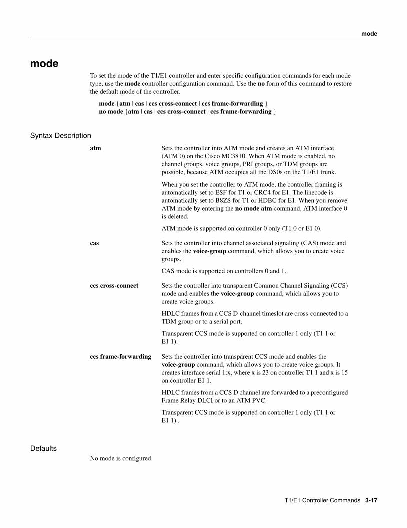
modeTo set the mode of the T1/E1 controller and enter specific configuration commands for each mode type, use the mode controller configuration command. Use the no form of this command to restore the default mode of the controller.
mode {atm | cas | ccs cross-connect | ccs frame-forwarding }no mode {atm | cas | ccs cross-connect | ccs frame-forwarding }
Syntax Description
DefaultsNo mode is configured.
atm Sets the controller into ATM mode and creates an ATM interface (ATM 0) on the Cisco MC3810. When ATM mode is enabled, no channel groups, voice groups, PRI groups, or TDM groups are possible, because ATM occupies all the DS0s on the T1/E1 trunk.
When you set the controller to ATM mode, the controller framing is automatically set to ESF for T1 or CRC4 for E1. The linecode is automatically set to B8ZS for T1 or HDBC for E1. When you remove ATM mode by entering the no mode atm command, ATM interface 0 is deleted.
ATM mode is supported on controller 0 only (T1 0 or E1 0).
cas Sets the controller into channel associated signaling (CAS) mode and enables the voice-group command, which allows you to create voice groups.
CAS mode is supported on controllers 0 and 1.
ccs cross-connect Sets the controller into transparent Common Channel Signaling (CCS) mode and enables the voice-group command, which allows you to create voice groups.
HDLC frames from a CCS D-channel timeslot are cross-connected to a TDM group or to a serial port.
Transparent CCS mode is supported on controller 1 only (T1 1 or E1 1).
ccs frame-forwarding Sets the controller into transparent CCS mode and enables the voice-group command, which allows you to create voice groups. It creates interface serial 1:x, where x is 23 on controller T1 1 and x is 15 on controller E1 1.
HDLC frames from a CCS D channel are forwarded to a preconfigured Frame Relay DLCI or to an ATM PVC.
Transparent CCS mode is supported on controller 1 only (T1 1 orE1 1) .
T1/E1 Controller Commands 3-17
mode
Command ModeController configuration
Command History
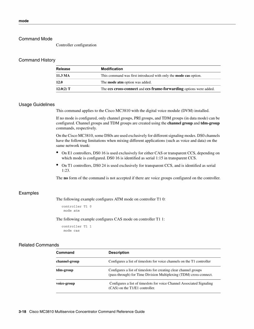
Usage GuidelinesThis command applies to the Cisco MC3810 with the digital voice module (DVM) installed.
If no mode is configured, only channel groups, PRI groups, and TDM groups (in data mode) can be configured. Channel groups and TDM groups are created using the channel group and tdm-group commands, respectively.
On the Cisco MC3810, some DS0s are used exclusively for different signaling modes. DS0 channels have the following limitations when mixing different applications (such as voice and data) on the same network trunk:
• On E1 controllers, DS0 16 is used exclusively for either CAS or transparent CCS, depending on which mode is configured. DS0 16 is identified as serial 1:15 in transparent CCS.
• On T1 controllers, DS0 24 is used exclusively for transparent CCS, and is identified as serial 1:23.
The no form of the command is not accepted if there are voice groups configured on the controller.
ExamplesThe following example configures ATM mode on controller T1 0:
controller T1 0 mode atm
The following example configures CAS mode on controller T1 1:
controller T1 1 mode cas
Related Commands
Release Modification
11.3 MA This command was first introduced with only the mode cas option.
12.0 The mode atm option was added.
12.0(2) T The ccs cross-connect and ccs frame-forwarding options were added.
Command Description
channel-group Configures a list of timeslots for voice channels on the T1 controller
tdm-group Configures a list of timeslots for creating clear channel groups (pass-through) for Time Division Multiplexing (TDM) cross-connect.
voice-group Configures a list of timeslots for voice Channel Associated Signaling (CAS) on the T1/E1 controller.
3-18 Cisco MC3810 Multiservice Concentrator Command Reference Guide
pri-group
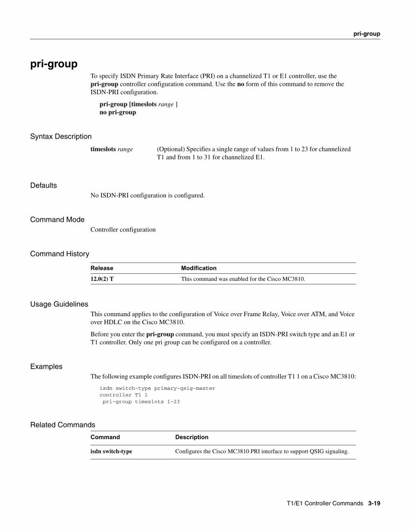
pri-groupTo specify ISDN Primary Rate Interface (PRI) on a channelized T1 or E1 controller, use the pri-group controller configuration command. Use the no form of this command to remove the ISDN-PRI configuration.
pri-group [timeslots range ]no pri-group
Syntax Description
DefaultsNo ISDN-PRI configuration is configured.
Command ModeController configuration
Command History
Usage GuidelinesThis command applies to the configuration of Voice over Frame Relay, Voice over ATM, and Voice over HDLC on the Cisco MC3810.
Before you enter the pri-group command, you must specify an ISDN-PRI switch type and an E1 or T1 controller. Only one pri group can be configured on a controller.
ExamplesThe following example configures ISDN-PRI on all timeslots of controller T1 1 on a Cisco MC3810:
isdn switch-type primary-qsig-mastercontroller T1 1pri-group timeslots 1-23
Related Commands
timeslots range (Optional) Specifies a single range of values from 1 to 23 for channelized T1 and from 1 to 31 for channelized E1.
Release Modification
12.0(2) T This command was enabled for the Cisco MC3810.
Command Description
isdn switch-type Configures the Cisco MC3810 PRI interface to support QSIG signaling.
T1/E1 Controller Commands 3-19
tdm-group
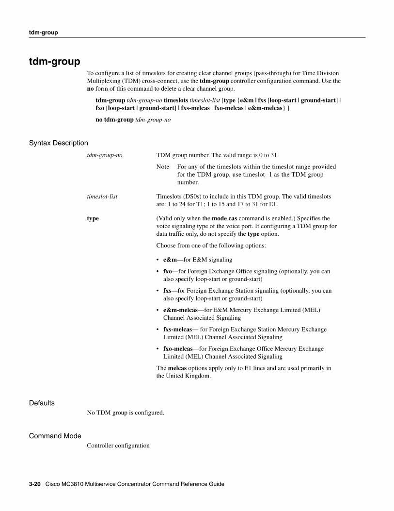
tdm-groupTo configure a list of timeslots for creating clear channel groups (pass-through) for Time Division Multiplexing (TDM) cross-connect, use the tdm-group controller configuration command. Use the no form of this command to delete a clear channel group.
tdm-group tdm-group-no timeslots timeslot-list [type {e&m | fxs [loop-start | ground-start] | fxo [loop-start | ground-start] | fxs-melcas | fxo-melcas | e&m-melcas} ]
no tdm-group tdm-group-no
Syntax Description
DefaultsNo TDM group is configured.
Command ModeController configuration
tdm-group-no TDM group number. The valid range is 0 to 31.
Note For any of the timeslots within the timeslot range provided for the TDM group, use timeslot -1 as the TDM group number.
timeslot-list Timeslots (DS0s) to include in this TDM group. The valid timeslots are: 1 to 24 for T1; 1 to 15 and 17 to 31 for E1.
type (Valid only when the mode cas command is enabled.) Specifies the voice signaling type of the voice port. If configuring a TDM group for data traffic only, do not specify the type option.
Choose from one of the following options:
• e&m—for E&M signaling
• fxo—for Foreign Exchange Office signaling (optionally, you can also specify loop-start or ground-start)
• fxs—for Foreign Exchange Station signaling (optionally, you can also specify loop-start or ground-start)
• e&m-melcas—for E&M Mercury Exchange Limited (MEL) Channel Associated Signaling
• fxs-melcas— for Foreign Exchange Station Mercury Exchange Limited (MEL) Channel Associated Signaling
• fxo-melcas—for Foreign Exchange Office Mercury Exchange Limited (MEL) Channel Associated Signaling
The melcas options apply only to E1 lines and are used primarily in the United Kingdom.
3-20 Cisco MC3810 Multiservice Concentrator Command Reference Guide
tdm-group
Command History
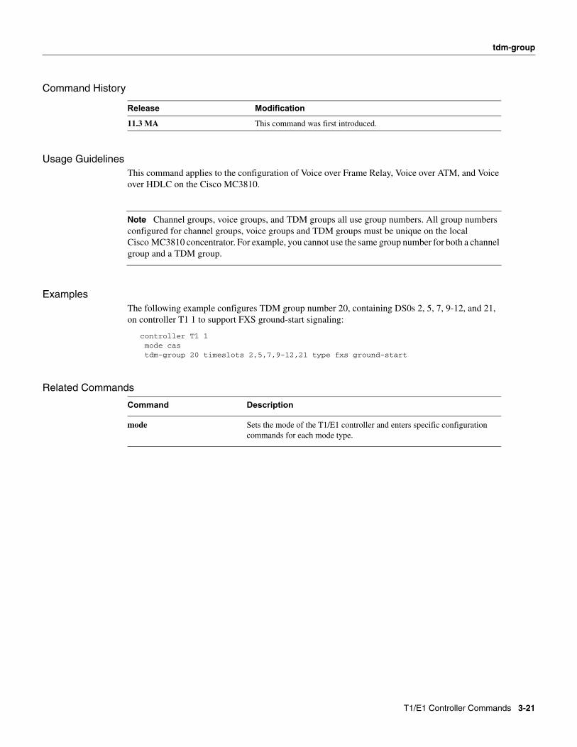
Usage GuidelinesThis command applies to the configuration of Voice over Frame Relay, Voice over ATM, and Voice over HDLC on the Cisco MC3810.
Note Channel groups, voice groups, and TDM groups all use group numbers. All group numbers configured for channel groups, voice groups and TDM groups must be unique on the local Cisco MC3810 concentrator. For example, you cannot use the same group number for both a channel group and a TDM group.
ExamplesThe following example configures TDM group number 20, containing DS0s 2, 5, 7, 9-12, and 21, on controller T1 1 to support FXS ground-start signaling:
controller T1 1 mode cas tdm-group 20 timeslots 2,5,7,9-12,21 type fxs ground-start
Related Commands
Release Modification
11.3 MA This command was first introduced.
Command Description
mode Sets the mode of the T1/E1 controller and enters specific configuration commands for each mode type.
T1/E1 Controller Commands 3-21
voice-group
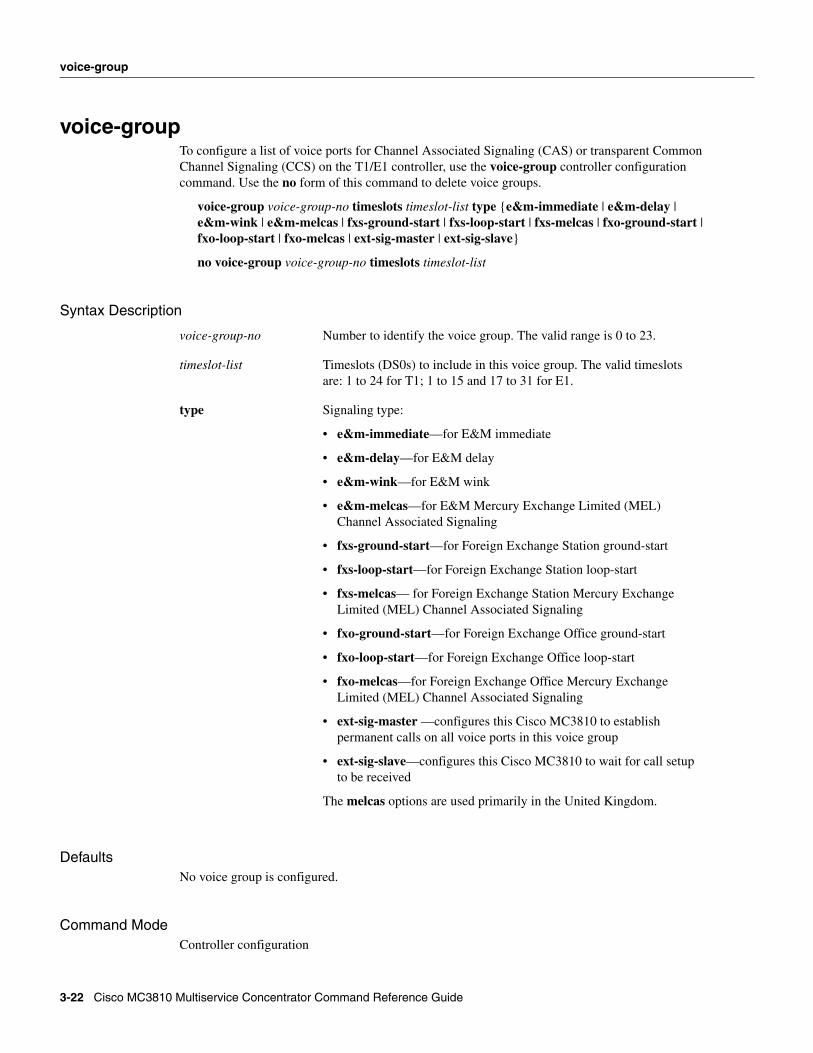
voice-groupTo configure a list of voice ports for Channel Associated Signaling (CAS) or transparent Common Channel Signaling (CCS) on the T1/E1 controller, use the voice-group controller configuration command. Use the no form of this command to delete voice groups.
voice-group voice-group-no timeslots timeslot-list type {e&m-immediate | e&m-delay | e&m-wink | e&m-melcas | fxs-ground-start | fxs-loop-start | fxs-melcas | fxo-ground-start | fxo-loop-start | fxo-melcas | ext-sig-master | ext-sig-slave}
no voice-group voice-group-no timeslots timeslot-list
Syntax Description
DefaultsNo voice group is configured.
Command ModeController configuration
voice-group-no Number to identify the voice group. The valid range is 0 to 23.
timeslot-list Timeslots (DS0s) to include in this voice group. The valid timeslots are: 1 to 24 for T1; 1 to 15 and 17 to 31 for E1.
type Signaling type:
• e&m-immediate—for E&M immediate
• e&m-delay—for E&M delay
• e&m-wink—for E&M wink
• e&m-melcas—for E&M Mercury Exchange Limited (MEL) Channel Associated Signaling
• fxs-ground-start—for Foreign Exchange Station ground-start
• fxs-loop-start—for Foreign Exchange Station loop-start
• fxs-melcas— for Foreign Exchange Station Mercury Exchange Limited (MEL) Channel Associated Signaling
• fxo-ground-start—for Foreign Exchange Office ground-start
• fxo-loop-start—for Foreign Exchange Office loop-start
• fxo-melcas—for Foreign Exchange Office Mercury Exchange Limited (MEL) Channel Associated Signaling
• ext-sig-master —configures this Cisco MC3810 to establish permanent calls on all voice ports in this voice group
• ext-sig-slave—configures this Cisco MC3810 to wait for call setup to be received
The melcas options are used primarily in the United Kingdom.
3-22 Cisco MC3810 Multiservice Concentrator Command Reference Guide
voice-group
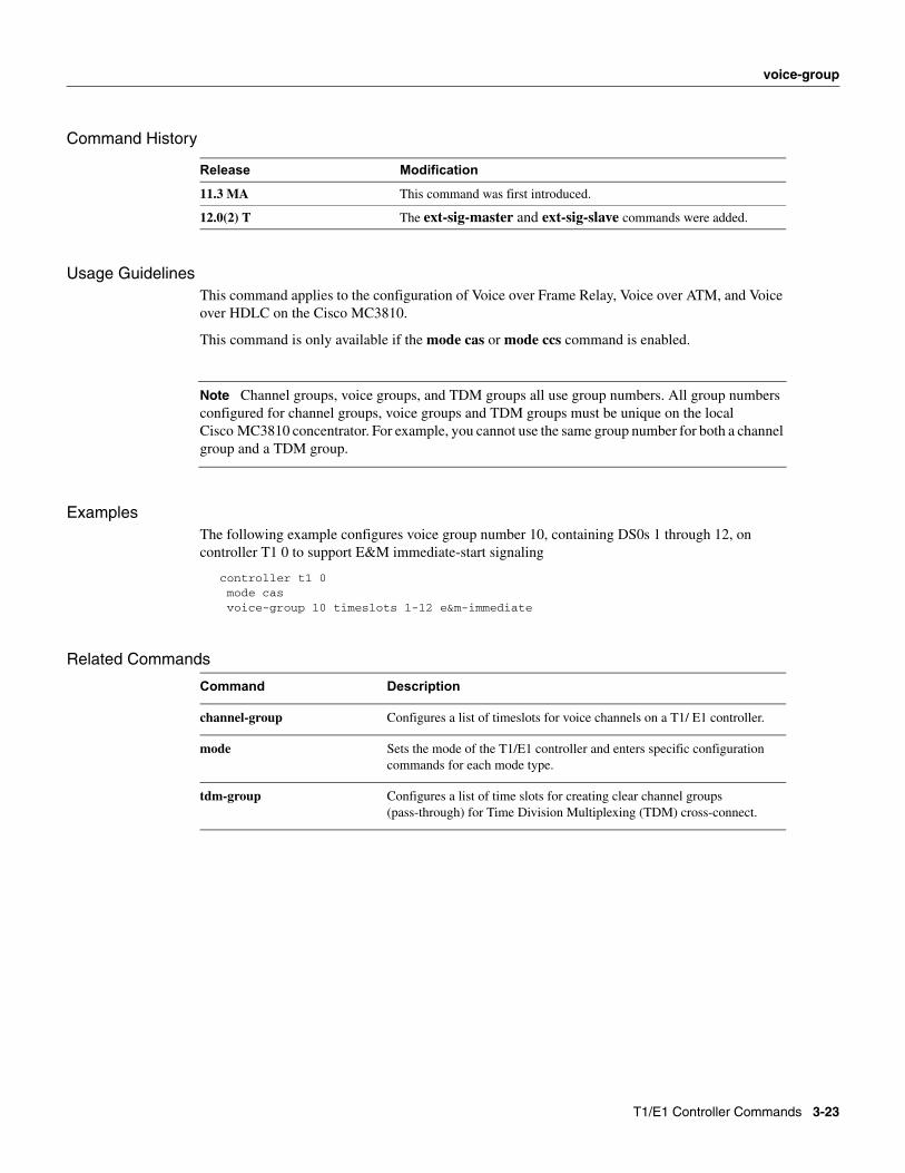
Command History
Usage GuidelinesThis command applies to the configuration of Voice over Frame Relay, Voice over ATM, and Voice over HDLC on the Cisco MC3810.
This command is only available if the mode cas or mode ccs command is enabled.
Note Channel groups, voice groups, and TDM groups all use group numbers. All group numbers configured for channel groups, voice groups and TDM groups must be unique on the local Cisco MC3810 concentrator. For example, you cannot use the same group number for both a channel group and a TDM group.
ExamplesThe following example configures voice group number 10, containing DS0s 1 through 12, on controller T1 0 to support E&M immediate-start signaling
controller t1 0 mode cas voice-group 10 timeslots 1-12 e&m-immediate
Related Commands
Release Modification
11.3 MA This command was first introduced.
12.0(2) T The ext-sig-master and ext-sig-slave commands were added.
Command Description
channel-group Configures a list of timeslots for voice channels on a T1/ E1 controller.
mode Sets the mode of the T1/E1 controller and enters specific configuration commands for each mode type.
tdm-group Configures a list of time slots for creating clear channel groups (pass-through) for Time Division Multiplexing (TDM) cross-connect.
T1/E1 Controller Commands 3-23

voice-group
3-24 Cisco MC3810 Multiservice Concentrator Command Reference Guide