Embed Size (px)
Citation preview
City of Melville
Path
Guidelines and Specifications
Path Guidelines and Specifications
Uncontrolled Document When Printed - This Version: 22/06/2021 2:56 PM Page 2 of 21 Please refer to the BMS for the latest version
Latest Revision Details (Earlier Revision History is listed at end of document)
Date amended
Description of Change
(Provide sufficient detail so that staff familiar with the previous work instruction can update themselves on the changes easily)
Revised by (Document
Owner)
Approved by (Document
Owner’s Supervisor)
Date approved
3/6/2021
Review - Added words on complaint handling - Formatting changes including Revision History - Update Grab Rail Design in PAWs - Update pole offset wording
P Handcock K Brosztl 3/6/2021
Authorisation
WI Owner – Asset Management Coordinator
WI Approver – Manager, Engineering
Directorate of WI Owner – Technical Services
Path Guidelines and Specifications
Uncontrolled Document When Printed - This Version: 22/06/2021 2:56 PM Page 3 of 21 Please refer to the BMS for the latest version
1 Contents
1 Contents ................................................................................................................................................... 3
1 Introduction ............................................................................................................................................. 5
1.1 Objective .......................................................................................................................................... 5
1.2 Purpose ............................................................................................................................................ 5
1.3 Path Asset Management Plan .......................................................................................................... 5
1.4 Complaints ....................................................................................................................................... 5
1.5 Variations between the path standards .......................................................................................... 5
2 Path Design .............................................................................................................................................. 7
2.1 Path Position .................................................................................................................................... 7
2.2 Verge impacts and Crossover cut throughs ..................................................................................... 7
2.3 Path Widths ...................................................................................................................................... 8
2.4 Path Clearance - Vertical .................................................................................................................. 8
2.5 Path Clearance - Horizontal ............................................................................................................. 9
2.6 Path Material .................................................................................................................................... 9
2.7 Path/Verge Gradient and Cross fall ................................................................................................. 9
2.8 Paths in Public Access Ways (PAWs) .............................................................................................. 10
2.9 Kerbing ........................................................................................................................................... 10
3 Grab Rails ............................................................................................................................................... 11
3.1 General ........................................................................................................................................... 11
3.2 PAW Barriers .................................................................................................................................. 11
4 Tactile Indicators .................................................................................................................................... 13
4.1 Tactile Ground Surface Indicators (TGSI) ....................................................................................... 13
5 Pedestrian Ramps .................................................................................................................................. 14
5.1 Pedestrian Ramps .......................................................................................................................... 14
5.2 Redundant Pedestrian Ramps ........................................................................................................ 14
5.3 Designated Vehicle Crossing Point (Across a path)........................................................................ 14
6 Appendices ............................................................................................................................................. 15
6.1 References ...................................................................................................................................... 15
6.2 Drawings ......................................................................................................................................... 16
Path Guidelines and Specifications
Uncontrolled Document When Printed - This Version: 22/06/2021 2:56 PM Page 4 of 21 Please refer to the BMS for the latest version
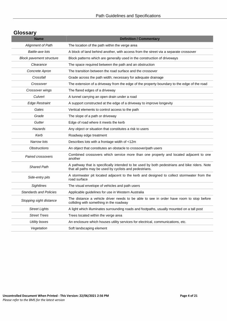
Glossary Name Definition / Commentary
Alignment of Path The location of the path within the verge area
Battle-axe lots A block of land behind another, with access from the street via a separate crossover
Block pavement structure Block patterns which are generally used in the construction of driveways
Clearance The space required between the path and an obstruction
Concrete Apron The transition between the road surface and the crossover
Crossfall Grade across the path width; necessary for adequate drainage
Crossover The extension of a driveway from the edge of the property boundary to the edge of the road
Crossover wings The flared edges of a driveway
Culvert A tunnel carrying an open drain under a road
Edge Restraint A support constructed at the edge of a driveway to improve longevity
Gates Vertical elements to control access to the path
Grade The slope of a path or driveway
Gutter Edge of road where it meets the kerb
Hazards Any object or situation that constitutes a risk to users
Kerb Roadway edge treatment
Narrow lots Describes lots with a frontage width of <12m
Obstructions An object that constitutes an obstacle to crossover/path users
Paired crossovers Combined crossovers which service more than one property and located adjacent to one another
Shared Path A pathway that is specifically intended to be used by both pedestrians and bike riders. Note that all paths may be used by cyclists and pedestrians.
Side-entry pits A stormwater pit located adjacent to the kerb and designed to collect stormwater from the road surface
Sightlines The visual envelope of vehicles and path users
Standards and Policies Applicable guidelines for use in Western Australia
Stopping sight distance The distance a vehicle driver needs to be able to see in order have room to stop before colliding with something in the roadway
Street Lights A light which illuminates surrounding roads and footpaths, usually mounted on a tall post
Street Trees Trees located within the verge area
Utility boxes An enclosure which houses utility services for electrical, communications, etc.
Vegetation Soft landscaping element
Path Guidelines and Specifications
Uncontrolled Document When Printed - This Version: 22/06/2021 2:56 PM Page 5 of 21 Please refer to the BMS for the latest version
1 Introduction
This document provides guidelines and specifications for the construction or renewal of paths in the City. It follows from the City’s Path Policy (CP-033) and refers to other documents and standards as appropriate. Significant portions of these guidelines are taken from the document “Planning and Designing for Pedestrians: Guidelines” November 2011 from the WA Department of Transport.
1.1 Objective
To provide detailed guidelines for the construction of paths in the City of Melville that meet the City’s policy and strategies. The Paths types covered are: • Footpath
• Shared Path
• Separated Footpath
Paths for the exclusive use of cyclists.
It does NOT include guidelines for deciding where paths will be constructed.
1.2 Purpose
This document comprises guidelines for planning and design of paths. It provides a consistent framework to enable the city and its contractors to understand and meet the requirements of the City of Melville. This Guideline provides for path design that references statutory and best-practice guidance documentation which includes information from the documents listed in Appendix 6.1
1.3 Path Asset Management Plan
Information on the proposed order for path construction and renewal, the future costs of path construction, renewal and maintenance etc. is covered in the Path Asset Management plan.
1.4 Complaints
All complaints and requests for review to be handled through the City’s normal processes as outlined in the Council Policy CP-101 Complaints Management Policy.
1.5 Variations between the path standards
Paths are long life assets and over time the City’s guidelines and specifications for their construction and inspection have evolved to meet community and compliance needs. The result is that there exist in the City many path assets that no longer meet the current guidelines and specifications. The City will not generally require changes to path assets that met the guidelines and specifications at the time when they were constructed. Reasons for change include:
Compliance with current legislative or similar requirements
Path Guidelines and Specifications
Uncontrolled Document When Printed - This Version: 22/06/2021 2:56 PM Page 6 of 21 Please refer to the BMS for the latest version
Changes required for the installation of other assets.
This document reflects the City’s current standards. Requests for variations to meet a previous standard for construction or inspection will be denied.
Path Guidelines and Specifications
Uncontrolled Document When Printed - This Version: 22/06/2021 2:56 PM Page 7 of 21 Please refer to the BMS for the latest version
2 Path Design
The intent is to provide for paths that:
Meet the City’s Path Policy
Meets the City’s Duty of Care
Provide for safe, connected and accessible paths
2.1 General Requirements
The slope of the road from the bottom of the kerb to the top of the crown should be no more than 3%.
A general requirement for paths is specifically requested in the community aspirations for Sustainable and Connected Transport and Healthy Lifestyles, as identified in the City’s Strategic Community Plan.
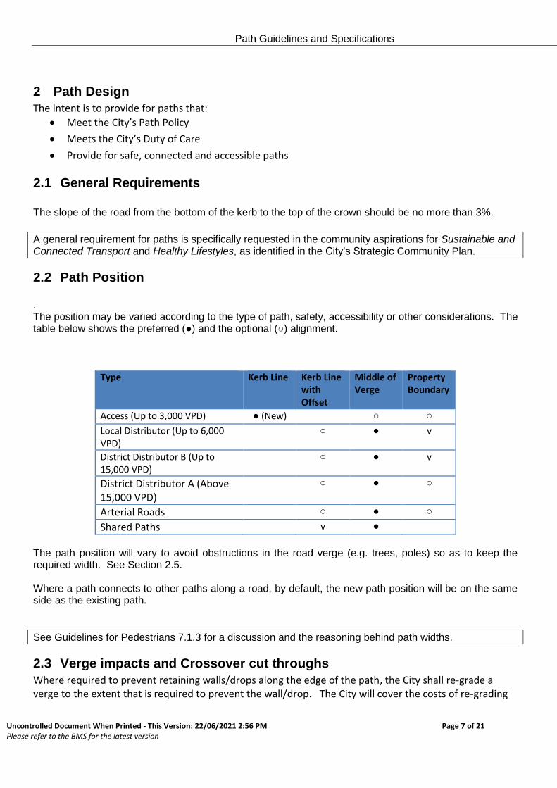
2.2 Path Position . The position may be varied according to the type of path, safety, accessibility or other considerations. The table below shows the preferred (●) and the optional (○) alignment.
Type Kerb Line Kerb Line with Offset
Middle of Verge
Property Boundary
Access (Up to 3,000 VPD) ● (New) ○ ○
Local Distributor (Up to 6,000 VPD)
○ ● v
District Distributor B (Up to 15,000 VPD)
○ ● v
District Distributor A (Above 15,000 VPD)
○ ●
○
Arterial Roads ○ ● ○
Shared Paths v ● The path position will vary to avoid obstructions in the road verge (e.g. trees, poles) so as to keep the required width. See Section 2.5. Where a path connects to other paths along a road, by default, the new path position will be on the same side as the existing path.
See Guidelines for Pedestrians 7.1.3 for a discussion and the reasoning behind path widths.
2.3 Verge impacts and Crossover cut throughs
Where required to prevent retaining walls/drops along the edge of the path, the City shall re-grade a verge to the extent that is required to prevent the wall/drop. The City will cover the costs of re-grading
Path Guidelines and Specifications
Uncontrolled Document When Printed - This Version: 22/06/2021 2:56 PM Page 8 of 21 Please refer to the BMS for the latest version
the verge and any affected irrigation systems to the extent that it would cost the City to perform the works. Where it is not practical, the City may construct a retaining wall. In areas of steep grades, the IPWEA Subdivision Guidelines Section 3.3.4: Verge and property grades states that the verge on the high side may be graded at 2.0% for three metres and then battered to suit the finished contours at a maximum of 16%. Where the construction of a path through a crossover requires additional works to enable the level of the crossovers and path to match, the City will cover the costs of the works to the extent that it would cost the City to perform the works. In these cases, the City must approve the design before works commence. All reinstatement will be in grey concrete except as agreed by the City. The City may replace existing aggregate style crossings (other than the path) with aggregate however no guarantee is made for colour matching or style. Embedded reinforcements (e.g. reo bar) are not allowed on residential crossings as they prevent easy access by service utilities. See also DOT Path Guidelines 7.5.2 and the IPWEA Subdivision Guidelines Section 3.3.4: Verge and property grades
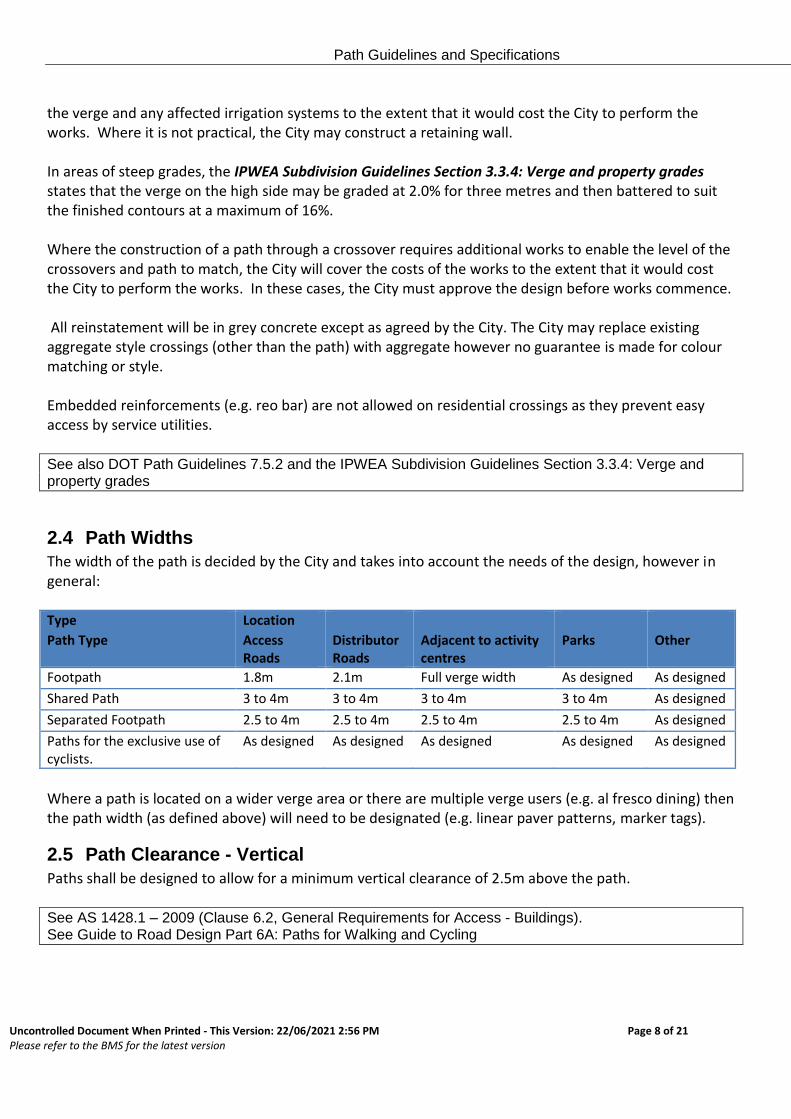
2.4 Path Widths
The width of the path is decided by the City and takes into account the needs of the design, however in general: Type Location
Path Type Access Roads
Distributor Roads
Adjacent to activity centres
Parks Other
Footpath 1.8m 2.1m Full verge width As designed As designed
Shared Path 3 to 4m 3 to 4m 3 to 4m 3 to 4m As designed
Separated Footpath 2.5 to 4m 2.5 to 4m 2.5 to 4m 2.5 to 4m As designed
Paths for the exclusive use of cyclists.
As designed As designed As designed As designed As designed
Where a path is located on a wider verge area or there are multiple verge users (e.g. al fresco dining) then the path width (as defined above) will need to be designated (e.g. linear paver patterns, marker tags).
2.5 Path Clearance - Vertical
Paths shall be designed to allow for a minimum vertical clearance of 2.5m above the path. See AS 1428.1 – 2009 (Clause 6.2, General Requirements for Access - Buildings). See Guide to Road Design Part 6A: Paths for Walking and Cycling
Path Guidelines and Specifications
Uncontrolled Document When Printed - This Version: 22/06/2021 2:56 PM Page 9 of 21 Please refer to the BMS for the latest version
2.6 Path Clearance - Horizontal
Paths will have a horizontal clearance between the edge of the path and any obstacle. Obstacles include retaining walls, light poles, trees. The design of the path will need to consider the obstacles (e.g. light poles) and determine the correct clearance and associated changes. An absolute minimum 0.3m horizontal clearance is required between the edges of a path and any obstacle. 0.5m is desirable. Shared paths will have a minimum 3m clearance with walls. Trees and lights to be located 2.7m from the property line as per the UPC. The City’s standards for path width will be kept unless there are exceptional circumstances as approved by the City.
See Austroads Guide to Road Design Part 6A Section 7.7 See also DOT Path Guidelines 7.1.3 See Utility Providers Code of Practice for Western Australia
2.7 Path Material
The path material will be fit for use with regard to colour, texture, surface finish and also meet accessibility requirements:
Type Material
Footpath Concrete
Shared Path As specified, generally asphalt
Separated Footpath As specified, generally asphalt
Paths for the exclusive use of cyclists. As specified, generally asphalt
Paths in Parks As specified
Areas covered by Activity Centre Plans As specified
The City will determine the appropriate material for all paths. Where paths and other existing assets are adjacent then alternative materials may be considered (e.g. permeable pavements adjacent to trees). Path design (including materials) will need to be reinforced where the path is likely to be driven on. This includes schools, industrial zones, along arterial roads and City activity centres.
2.8 Path/Verge Gradient and Cross fall
Construct and renew all paths with the recommended gradient and cross fall standards where reasonable. Where the impact of the design is impracticable, the City may construct a path anyway (e.g. non-DIAP complaint). Where this occurs, the City will document its reasons in a design study. It is desirable that cross fall be 2% with a maximum 2.5% to cater for people who have a disability.
Path Guidelines and Specifications
Uncontrolled Document When Printed - This Version: 22/06/2021 2:56 PM Page 10 of 21 Please refer to the BMS for the latest version
See Austroads Guide to Road Design 6A, Clause 7.6.
In most cases, path longitudinal gradients are dictated by the contours of the road. However, it is desirable that the longitudinal fall be 2.5% with a maximum of 1:14.
2.9 Paths in Public Access Ways (PAWs)
The area between the fence line and path should be stabilised where practical and resources allow. For example the use of, BSL stabilised limestone, liquid limestone, pebbles, grass, etc.
2.10 Kerbing
Where possible, kerbing adjacent to paths to be installed as semi-mountable. Kerbing to be 120mm height minimum. Any precast kerbing adjacent to paths will be replaced as part of the design. Suburbs built with mountable kerbs to have the same design retained unless otherwise required. See City of Melville Standard Kerb drawing.
Path Guidelines and Specifications
Uncontrolled Document When Printed - This Version: 22/06/2021 2:56 PM Page 11 of 21 Please refer to the BMS for the latest version
3 Grab Rails An upside down U shaped rail used to provide support for cyclists and pedestrians. It is primarily used at
kerb ramps and cut-throughs. Grab rails also act as an additional warning cue to motorists, about the
potential presence of pedestrian and cyclists crossing the roadway.
3.1 General
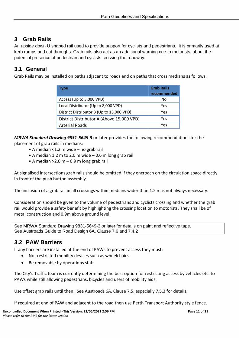
Grab Rails may be installed on paths adjacent to roads and on paths that cross medians as follows:
Type Grab Rails recommended
Access (Up to 3,000 VPD) No
Local Distributor (Up to 8,000 VPD) Yes
District Distributor B (Up to 15,000 VPD) Yes
District Distributor A (Above 15,000 VPD) Yes
Arterial Roads Yes
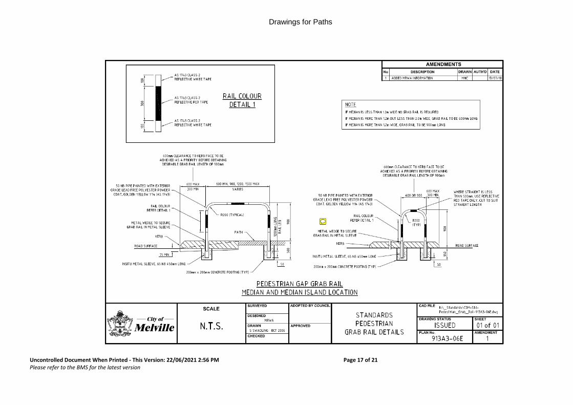
MRWA Standard Drawing 9831-5649-3 or later provides the following recommendations for the placement of grab rails in medians:
• A median <1.2 m wide – no grab rail • A median 1.2 m to 2.0 m wide – 0.6 m long grab rail • A median >2.0 m – 0.9 m long grab rail
At signalised intersections grab rails should be omitted if they encroach on the circulation space directly in front of the push button assembly. The inclusion of a grab rail in all crossings within medians wider than 1.2 m is not always necessary. Consideration should be given to the volume of pedestrians and cyclists crossing and whether the grab rail would provide a safety benefit by highlighting the crossing location to motorists. They shall be of metal construction and 0.9m above ground level. See MRWA Standard Drawing 9831-5649-3 or later for details on paint and reflective tape. See Austroads Guide to Road Design 6A, Clause 7.6 and 7.4.2
3.2 PAW Barriers
If any barriers are installed at the end of PAWs to prevent access they must:
Not restricted mobility devices such as wheelchairs
Be removable by operations staff
The City’s Traffic team is currently determining the best option for restricting access by vehicles etc. to PAWs while still allowing pedestrians, bicycles and users of mobility aids. Use offset grab rails until then. See Austroads 6A, Clause 7.5, especially 7.5.3 for details. If required at end of PAW and adjacent to the road then use Perth Transport Authority style fence.
Path Guidelines and Specifications
Uncontrolled Document When Printed - This Version: 22/06/2021 2:56 PM Page 12 of 21 Please refer to the BMS for the latest version
See Austroads Guide to Road Design 6A, Clause 7.5.2
Path Guidelines and Specifications
Uncontrolled Document When Printed - This Version: 22/06/2021 2:56 PM Page 13 of 21 Please refer to the BMS for the latest version
4 Tactile Indicators
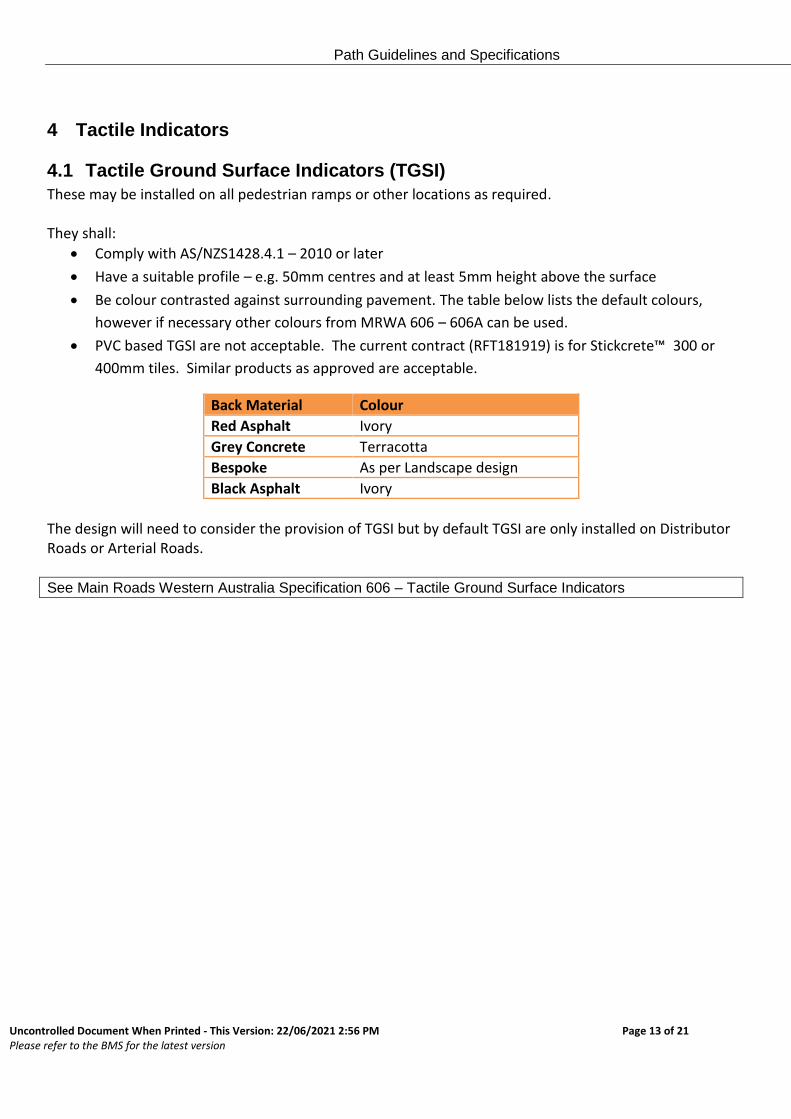
4.1 Tactile Ground Surface Indicators (TGSI)
These may be installed on all pedestrian ramps or other locations as required. They shall:
Comply with AS/NZS1428.4.1 – 2010 or later
Have a suitable profile – e.g. 50mm centres and at least 5mm height above the surface
Be colour contrasted against surrounding pavement. The table below lists the default colours,
however if necessary other colours from MRWA 606 – 606A can be used.
PVC based TGSI are not acceptable. The current contract (RFT181919) is for Stickcrete™ 300 or
400mm tiles. Similar products as approved are acceptable.
Back Material Colour
Red Asphalt Ivory
Grey Concrete Terracotta
Bespoke As per Landscape design
Black Asphalt Ivory
The design will need to consider the provision of TGSI but by default TGSI are only installed on Distributor Roads or Arterial Roads.
See Main Roads Western Australia Specification 606 – Tactile Ground Surface Indicators
Path Guidelines and Specifications
Uncontrolled Document When Printed - This Version: 22/06/2021 2:56 PM Page 14 of 21 Please refer to the BMS for the latest version
5 Pedestrian Ramps
5.1 Pedestrian Ramps
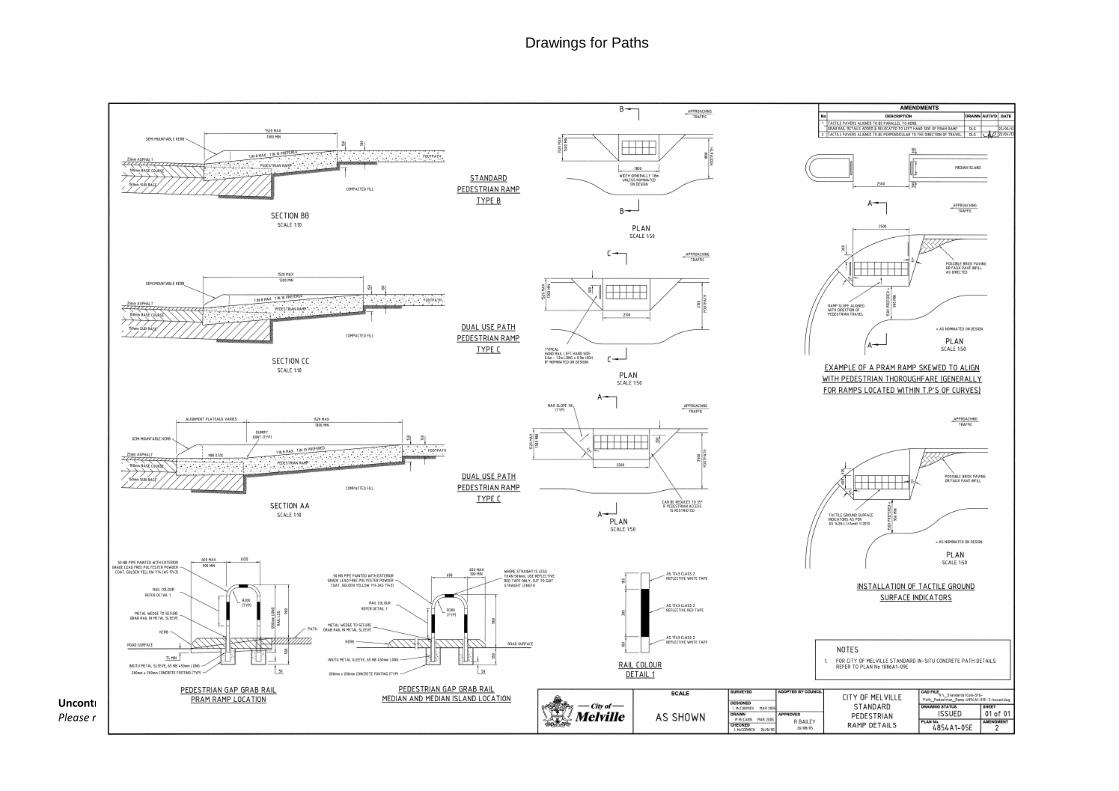
All ramps will meet AS/NZS1428.4.1 – 2009 or later. Ramps are to be located perpendicular to the direction of travel. The preferred gradient will be 1:10 with a maximum of 1:8. Finishes being in broom finished concrete. This provides the most suitable surface for a pedestrian ramp as it provides a firm, even, stable and slip resistant surface. Pedestrian Ramps shall match the width of the path except as required by the needs of the location. See COM drawing 485A1-05E.
5.2 Redundant Pedestrian Ramps
Redundant pedestrian ramps shall be removed and the verge, kerbing and footpath reinstated to match existing works and be in accordance with the City of Melville Verge Treatment Policy.
5.3 Designated Vehicle Crossing Point (Across a path)
Where access is required across a path for vehicles or similar then the crossing point shall:
Be suitably reinforced
Highlighted ( e.g. Etched X in concrete, change in colour )
Path Guidelines and Specifications
Uncontrolled Document When Printed - This Version: 22/06/2021 2:56 PM Page 15 of 21 Please refer to the BMS for the latest version
6 Appendices
6.1 References
Australian Standard 1428 - Design for access and mobility
Australian Standard AS1428.1: Design for access and mobility
Australian Standard AS2890.1:Off-street parking (2004)
Austroads AGRD Part 6A: Pedestrian and Cyclist Paths (AGRD6A/09)
Austroads Guide to Road Design
Austroads Guide to Road Design - Part 3: Geometric Design
Austroads Guide to Road Design - Part 6A: Pedestrian and Cyclist Paths
City of Melville Bike Plan
Crossover Guidelines and Specifications
Guidelines for Placement of Power Poles within Road Reserves in Built-Up Areas (Western Power,
2006)
IPWEA Local Government Guidelines for Subdivisional Development
Local Government (Uniform Local Provisions) Regulations 1996
Path AMP
Planning and Designing for Pedestrians: Guidelines November 2011 from the WA Department of
Transport.
Road Traffic Code 2000 (WA)
State Planning Policy 3.1 - Residential Design Codes (R-Codes)
WALGA Shared Path Design- Technical Guidelines
WAPC Liveable Neighbourhoods
Path Guidelines and Specifications
Uncontrolled Document When Printed - This Version: 22/06/2021 2:56 PM Page 16 of 21 Please refer to the BMS for the latest version
6.2 Drawings
Drawing Number Description
913A3-06E Standard pedestrian grab rail details
4854A1-05E Standard pedestrian ramp details
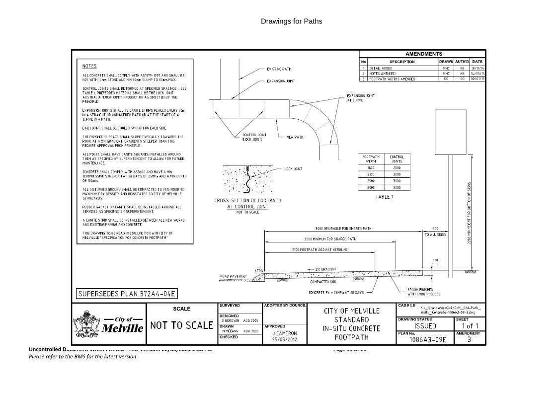
1086A3-09E Standard in-situ concrete footpath
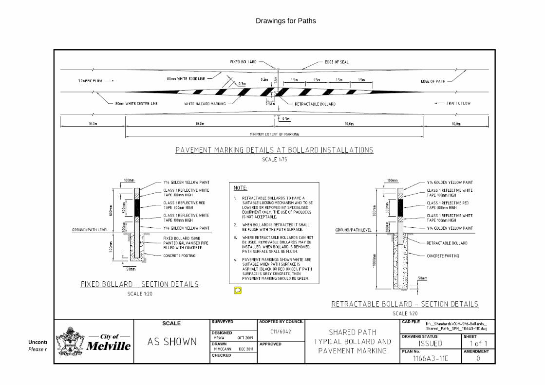
1166A3-11E Shared path typical bollard and pavement marking
Uncontrolled Document When Printed - This Version: 22/06/2021 2:56 PM Page 17 of 21 Please refer to the BMS for the latest version
Drawings for Paths
Uncontrolled Document When Printed - This Version: 22/06/2021 2:56 PM Page 18 of 21 Please refer to the BMS for the latest version
Drawings for Paths
Uncontrolled Document When Printed - This Version: 22/06/2021 2:56 PM Page 19 of 21 Please refer to the BMS for the latest version
Drawings for Paths
Uncontrolled Document When Printed - This Version: 22/06/2021 2:56 PM Page 20 of 21 Please refer to the BMS for the latest version
Drawings for Paths
Uncontrolled Document When Printed - This Version: 22/06/2021 2:56 PM Page 21 of 21 Please refer to the BMS for the latest version
Drawings for Paths
Revision History
Date
procedure amended
Description of Change Revised by
(Process Owner)
Approved by (Process Owner
supervisor)
Date approved
1/11/2019 Document Creation Paul Handcock Kimberly Brosztl
1/11/2019
27/6/2020 Review - Added words on complaint handling - Formatting changes including Revision
History
P Handcock K Brosztl 27/6/2020


![[MS-COM]: Component Object Model Plus (COM+) Protocol... · 2018-09-11 · Component Object Model Plus (COM+) Protocol Intellectual Property Rights Notice for Open Specifications](https://img.pdfslide.us/doc/110x75/5f478de3cf4db86df541cda3/ms-com-component-object-model-plus-com-protocol-2018-09-11-component.jpg)