Embed Size (px)
Citation preview
August 2009
255
Serial Report
Colour Metallography of Cast IronBy Zhou Jiyang, Professor, Dalian University of Technology, China
Translated by Ph.D Liu Jincheng, Fellow of Institute of Cast Metal Engineers, UK
This book consists of five sections: Chapter 1 Introduction, Chapter 2 Grey Iron, Chapter 3 Ductile Iron, Chapter 4 Vermicular Cast Iron, and Chapter 5 White Cast Iron. CHINA FOUNDRY publishs this book in several parts serially, starting from the first issue of 2009.
2.3 Crystallization of primary austenite in grey iron2.3.1 Crystallization thermodynamics of primary austenite The first precipitated phase in hypoeutectic cast iron is austenite,
called primary austenite. Figure 2-10 shows the free energy change
of primary austenite crystallization. When liquid hypoeutectic
cast iron with composition X is undercooled below liquidus
temperature BC', for example temperature T1, primary austenite
starts to crystallize. At this time, the iron atoms concentration
is higher than equilibrium value by (Xa-X); the free energy
of the iron melt with X is ΔG higher than that of equilibrium
mixture of iron melt with Xa and austenite with Xb, thus forming
thermodynamic driving force for primary austenite crystallization.
The austenite formed at beginning contains carbon Xa, the liquid
near to it also has similar carbon, but the region far away from
the austenite still has equilibrium carbon X, thus forming non-
uniformed carbon concentration and chemical potential in carbon.
Under driving by concentration difference, carbon diffuses from
the melt near to austenite towards outside, causing carbon in the
liquid near to austenite to decrease, thus the iron is oversaturated
gradually, leading to continuous austenite precipitation with
temperature decreasing. When temperature is undercooled to T2,
the concentration condition for new austenite to precipitate is
ready; austenite will grow in the front of original austenite.
2.3.2 Nucleation of primary austeniteNuclei of primary austenite are first formed on the wall of mould
cavity, since the biggest undercooling is resulted in here due to fast
heat transfer of mould wall. When the undercooling is greater than
that demanded for austenite nucleation, the nucleation is started.
The constitutional undercooling due to enrichment of C, Mn, S
and P elements in front of liquid/solid interface further promotes
nucleation process. Temperature fluctuation and liquid flow cause
some of dendrites to drop off from wall of mould cavity, which
float to inside and create ‘crystal propagation’ and become new
austenite nuclei. Furthermore, the addition of nucleation materials
is an effective measure to induce austenite nucleation.
Factors influencing austenite nucleation are:
(1). Undercooling condition: experiments have confirmed [21]
that when chemical composition is fixed, fast cooling rate,
high superheating and long holding time all cause difficulty for
austenite nucleation. This is because, on one hand, with increasing
cooling rate, the nucleation temperature of austenite is decreased
(that is undercooling is increased), giving rise to reduced number
of nuclei. On the other hand, high superheating and long holding
time will destroy existing heterogeneous nuclei or make them less
effective, giving rise to decreased number of nuclei.
However, Stefanescu[22] obtained an opposite relation:
N = 2.45ΔT 0.93
Where, N - number of austenite grains (N/mm2)
ΔT - undercooling (K)
That is, with increasing undercooling, the number of austenite
grains is increased.
(2). Addition of heterogeneous nuclei: the substances
able to become heterogeneous nuclei need not only to satisfy
Chapter 2
Grey Iron (II)
Fig. 2-10: Free energy change of primary austenite crystallization
256
CHINA FOUNDRY Vol.6 No.3
then branches and forms a dendrite (see Fig.2-13). The growth
processes of primary, secondary and third crystal axis are: at the
beginning stage of growth, the fast growth at tips of the octahedra
consisting of (001) plane leads to a primary dendrite formation.
Due to the natural packing process at the closest plane (001)
and constitutional undercooling at the region of melt close to
the crystal, projections or protrusions (the original places of the
secondary dendrite) grow and form at the primary dendrite axis
periodically, then grow into secondary crystal axes; then, third
crystal axes grow on the secondary dendrites. Secondary and third
dendrites all grow along the [100] direction and perpendicularly
each other. Thus, it is clear that the ‘constitutional undercooling’
causes the morphology of austenite to develop sequentially from
plane crystal into cellular crystal, cellular dendrite, and then
dendrite crystal.
Fig. 2-13: Development process from octahedral crystal to dendrite stem
There exist two types of austenite dendrite morphologies [24]:
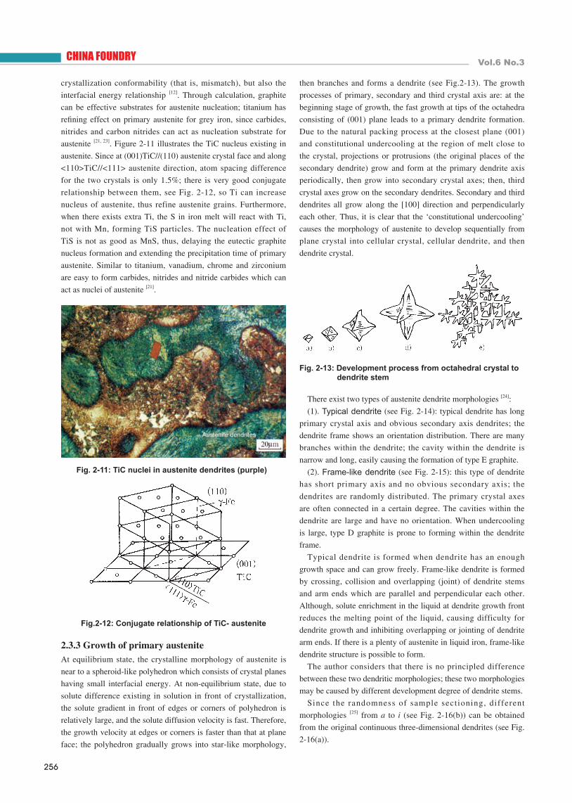
(1). Typical dendrite (see Fig. 2-14): typical dendrite has long
primary crystal axis and obvious secondary axis dendrites; the
dendrite frame shows an orientation distribution. There are many
branches within the dendrite; the cavity within the dendrite is
narrow and long, easily causing the formation of type E graphite.
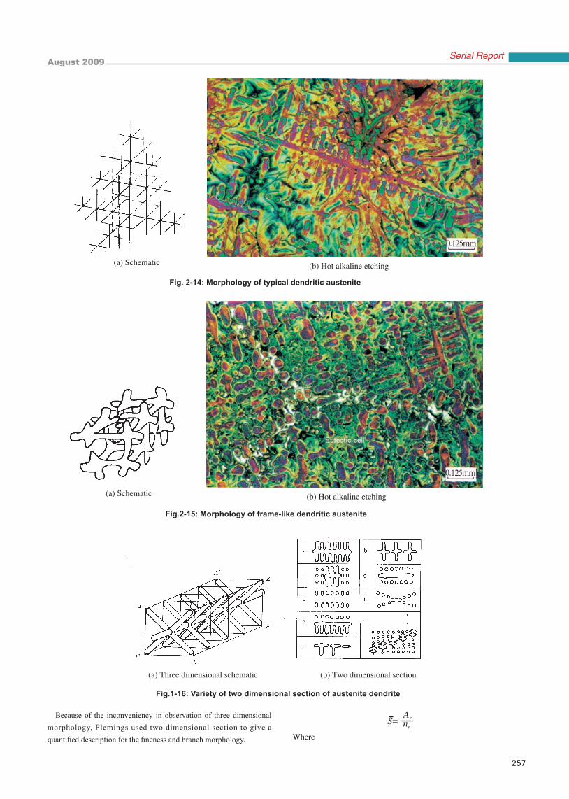
(2). Frame-like dendrite (see Fig. 2-15): this type of dendrite
has short primary axis and no obvious secondary axis; the
dendrites are randomly distributed. The primary crystal axes
are often connected in a certain degree. The cavities within the
dendrite are large and have no orientation. When undercooling
is large, type D graphite is prone to forming within the dendrite
frame.
Typical dendrite is formed when dendrite has an enough
growth space and can grow freely. Frame-like dendrite is formed
by crossing, collision and overlapping (joint) of dendrite stems
and arm ends which are parallel and perpendicular each other.
Although, solute enrichment in the liquid at dendrite growth front
reduces the melting point of the liquid, causing difficulty for
dendrite growth and inhibiting overlapping or jointing of dendrite
arm ends. If there is a plenty of austenite in liquid iron, frame-like
dendrite structure is possible to form.
The author considers that there is no principled difference
between these two dendritic morphologies; these two morphologies
may be caused by different development degree of dendrite stems.
Since the randomness of sample sectioning, different
morphologies [25] from a to i (see Fig. 2-16(b)) can be obtained
from the original continuous three-dimensional dendrites (see Fig.
2-16(a)).
crystallization conformability (that is, mismatch), but also the
interfacial energy relationship [12]. Through calculation, graphite
can be effective substrates for austenite nucleation; titanium has
refining effect on primary austenite for grey iron, since carbides,
nitrides and carbon nitrides can act as nucleation substrate for
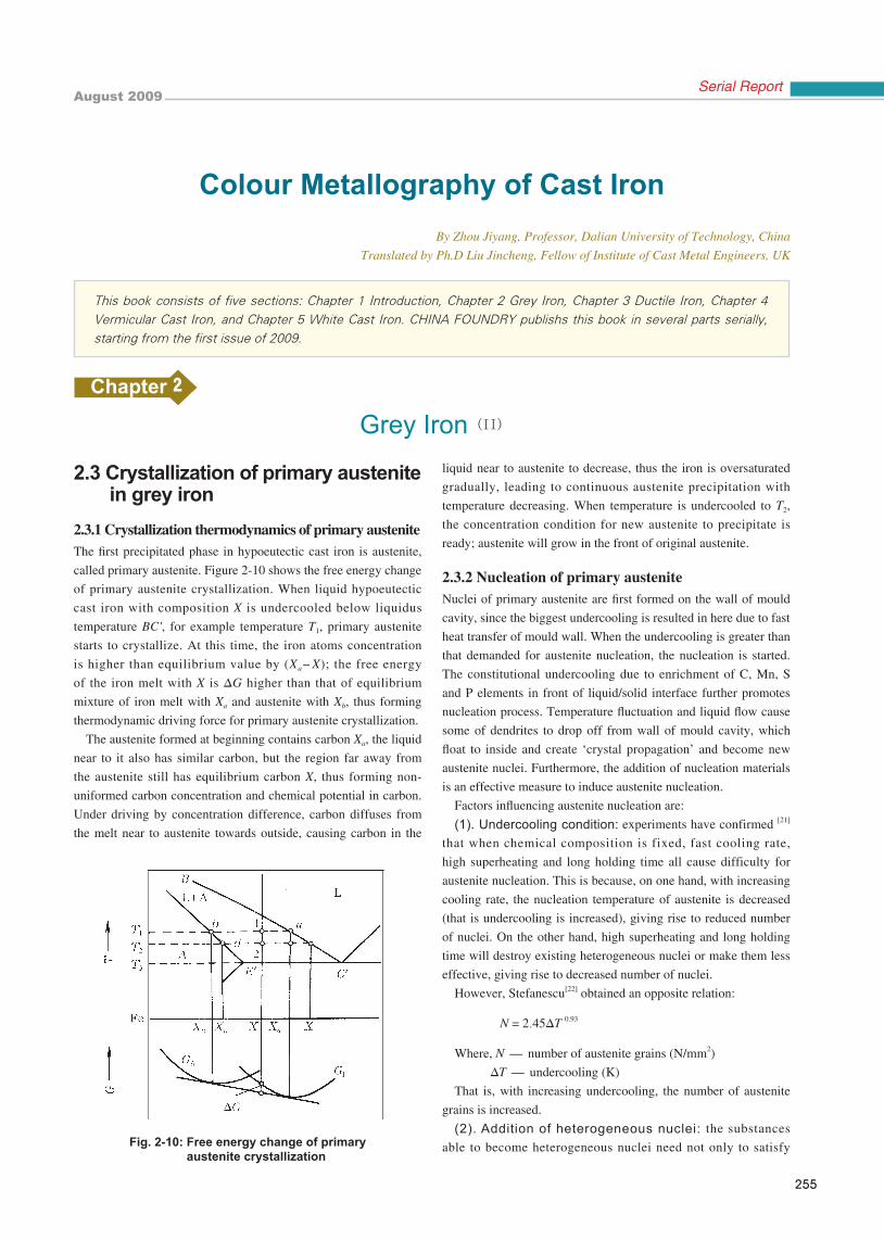
austenite [21, 23]. Figure 2-11 illustrates the TiC nucleus existing in
austenite. Since at (001)TiC//(110) austenite crystal face and along
<110>TiC//<111> austenite direction, atom spacing difference
for the two crystals is only 1.5%; there is very good conjugate
relationship between them, see Fig. 2-12, so Ti can increase
nucleus of austenite, thus refine austenite grains. Furthermore,
when there exists extra Ti, the S in iron melt will react with Ti,
not with Mn, forming TiS particles. The nucleation effect of
TiS is not as good as MnS, thus, delaying the eutectic graphite
nucleus formation and extending the precipitation time of primary
austenite. Similar to titanium, vanadium, chrome and zirconium
are easy to form carbides, nitrides and nitride carbides which can
act as nuclei of austenite [21].
Fig. 2-11: TiC nuclei in austenite dendrites (purple)
Fig.2-12: Conjugate relationship of TiC- austenite
2.3.3 Growth of primary austeniteAt equilibrium state, the crystalline morphology of austenite is
near to a spheroid-like polyhedron which consists of crystal planes
having small interfacial energy. At non-equilibrium state, due to
solute difference existing in solution in front of crystallization,
the solute gradient in front of edges or corners of polyhedron is
relatively large, and the solute diffusion velocity is fast. Therefore,
the growth velocity at edges or corners is faster than that at plane
face; the polyhedron gradually grows into star-like morphology,
August 2009
257
Serial Report
Fig.1-16: Variety of two dimensional section of austenite dendrite
Because of the inconveniency in observation of three dimensional morphology, Flemings used two dimensional section to give a quantified description for the fineness and branch morphology. Where
Fig. 2-14: Morphology of typical dendritic austenite
(a) Schematic (b) Hot alkaline etching
Fig.2-15: Morphology of frame-like dendritic austenite
(a) Schematic (b) Hot alkaline etching
(a) Three dimensional schematic (b) Two dimensional section
258
CHINA FOUNDRY Vol.6 No.3
-Dendrite morphology, refers to section area of each egg-
like section (mm2/egg-like section)
Ar-The total section area of austenite dendrites, (mm2)
nr-The number of sectioned austenite dendrites (number)
The smaller the is, the more the branching is. The dendrite
with well-developed secondary dendrites belongs to fine dendrites.
The factors affecting dendrite growth include cooling rate,
chemical composition and undercooling.
Under fast cooling condition, carbon atoms in the liquid at the
side of dendrite have not got enough time to diffuse to far away,
thus restricting the lateral growth of dendrite axis. In addition,
austenite heterogeneous nuclei have no enough time to diffuse
away, therefore increasing the opportunity for new dendrites to
grow from the side of primary dendrite (that is the secondary
or third crystal axes) [26]. In the end, all these promote austenite
to grow into more branched, fine and small dendrites with long
and fine main stem. This type of dendrite is often observed in
thin section castings, die castings or the region close to mould
wall; while in thick section and under slow cooling condition, the
structure is mainly coarse, frame-like dendrites.
Carbon equivalent is another important factor influencing
dendrite growth. With decrease of carbon equivalent, the length of
primary austenite dendrite increases.
Alloying elements exert significant influence on the morphology
of austenite dendrites [23,27,28]. Alloying elements V, Mo, B and Ce
promote secondary dendrites and reduce dendrite spacing; Ti, Cu,
Al, Cr and Bi make dendrites random distribution; Ni enlarges
dendrite spacing, reduces branching and promotes short and coarse
austenite. The influence mechanism of those elements is not clear
up to now; it may be related to undercooling, nucleation and
segregation caused by the elements.
The relationship between austenite dendrite growth velocity and
undercooling is[23]:
v = a△T n
Where v - growth velocity of dendrite tip (mm/s)
△T - undercooling (K)
a - constant
n - 1.5–3.0
Too high superheating and holding for a long time for iron
melt will increase undercooling, thus prolong dendrite length and
cause austenite dendrites more obvious orientation distribution[21].Inoculation of iron melt by SiC reduces undercooling of primary
austenite; at this time, short austenite dendrites can be observed [29].
2.3.4 Macro solidification morphology of primary austeniteAccording to alloying content, nucleation state and cooling
condition, primary austenite can precipitate by exogenous or
endogenous models.
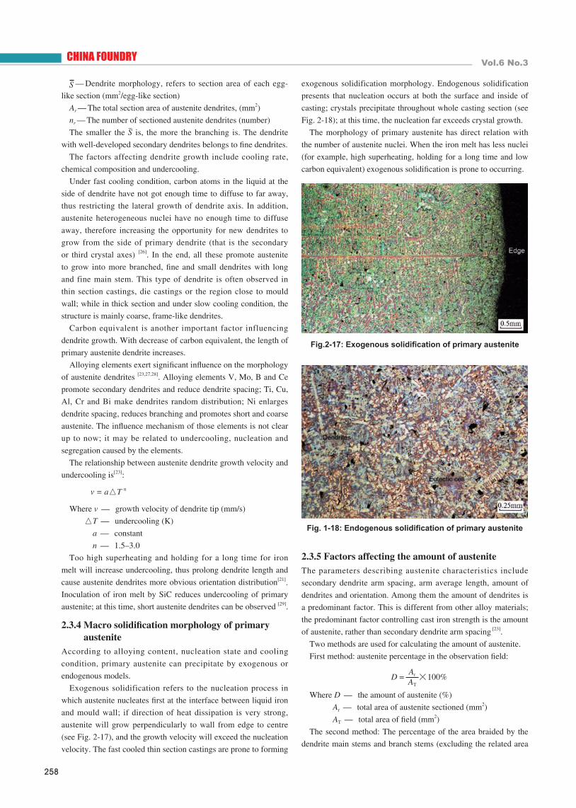
Exogenous solidification refers to the nucleation process in
which austenite nucleates first at the interface between liquid iron
and mould wall; if direction of heat dissipation is very strong,
austenite will grow perpendicularly to wall from edge to centre
(see Fig. 2-17), and the growth velocity will exceed the nucleation
velocity. The fast cooled thin section castings are prone to forming
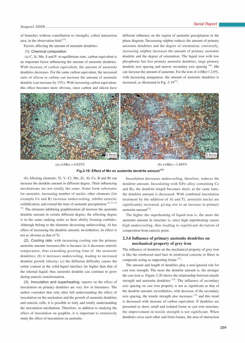
exogenous solidification morphology. Endogenous solidification
presents that nucleation occurs at both the surface and inside of
casting; crystals precipitate throughout whole casting section (see
Fig. 2-18); at this time, the nucleation far exceeds crystal growth.
The morphology of primary austenite has direct relation with
the number of austenite nuclei. When the iron melt has less nuclei
(for example, high superheating, holding for a long time and low
carbon equivalent) exogenous solidification is prone to occurring.
2.3.5 Factors affecting the amount of austenite The parameters describing austenite characteristics include
secondary dendrite arm spacing, arm average length, amount of
dendrites and orientation. Among them the amount of dendrites is
a predominant factor. This is different from other alloy materials;
the predominant factor controlling cast iron strength is the amount
of austenite, rather than secondary dendrite arm spacing [23].
Two methods are used for calculating the amount of austenite.
First method: austenite percentage in the observation field:
Where D - the amount of austenite (%)
Ar - total area of austenite sectioned (mm2)
AT - total area of field (mm2)
The second method: The percentage of the area braided by the
dendrite main stems and branch stems (excluding the related area
Fig.2-17: Exogenous solidification of primary austenite
Fig. 1-18: Endogenous solidification of primary austenite
August 2009
259
Serial Report
of branches without contribution to strength), called interaction
area, in the observation field [23].
Factors affecting the amount of austenite dendrites:
(1). Chemical composition (a) C, Si, Mn, S and P: at equilibrium state, carbon equivalent is
an important factor influencing the amount of austenite dendrites.
With increase of carbon equivalent, the amount of austenite
dendrites decreases. For the same carbon equivalent, the increased
ratio of silicon to carbon can increase the amount of austenite
dendrite (can increase by 15%). With increasing carbon equivalent,
this effect becomes more obvious, since carbon and silicon have
different influence on the region of austenite precipitation in the
phase diagram. Decreasing sulphur reduces the amount of primary
austenite dendrites and the degree of orientation; conversely,
increasing sulphur increases the amount of primary austenite
dendrite and the degree of orientation. The liquid iron with low
phosphorus has less primary austenite dendrites, large primary
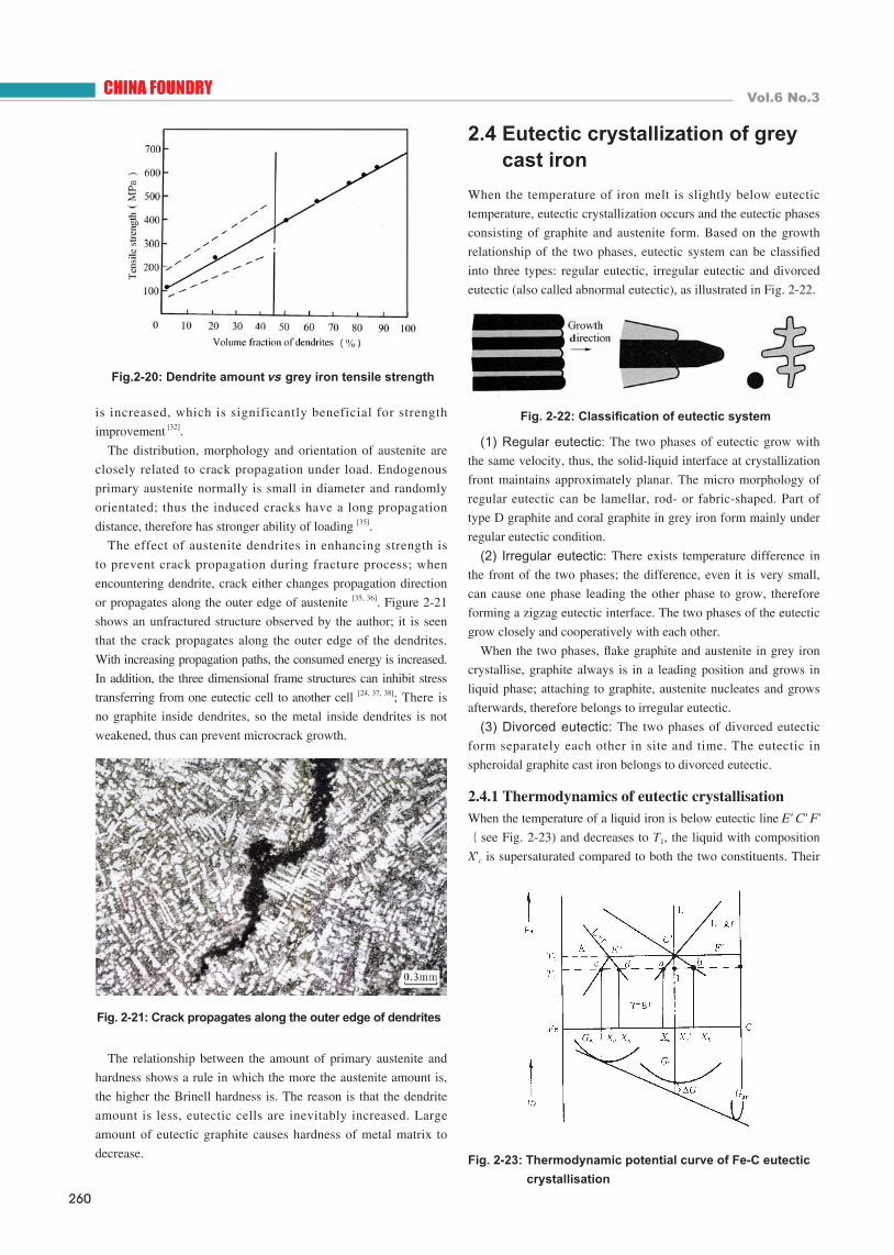
dendrite axis spacing and narrow secondary axis spacing [30]. Mn
can increase the amount of austenite. For the iron of w(Mn)≤2.0%,
with increasing manganese, the amount of austenite dendrites is
increased, as illustrated in Fig. 2-19[31].
(b) Alloying elements: Ti, V, Cr, Mo, Zr, Al, Ce, B and Bi can
increase the dendrite amount in different degree. Their influencing
mechanisms are not totally the same. Some form substrates
for austenite, increasing number of nuclei; other elements (for
example Ce and B) increase undercooling, inhibit eutectic
solidification, and extend the time of austenite precipitation [23, 27, 28,
32]. The elements inhibiting graphitization all increase the austenite
dendrite amount in certain different degree; the effecting degree
is in the same ranking order as their ability forming carbides.
Although belong to the elements decreasing undercooling, Al has
effect of increasing the dendrite amount; nevertheless, its effect is
not as obvious as that of Ti.
(2). Cooling rate: with increasing cooling rate the primary
austenite amount increases,this is because (a) it decreases eutectic
temperature, thus extending growing time of the austenite
dendrites; (b) it increases undercooling, leading to increased
dendrite growth velocity; (c) the diffusion difficulty causes the
solute content at the solid-liquid interface far higher than that of
the internal liquid; thus austenite dendrite can continue to grow
during eutectic transformation.
(3). Inoculation and superheating: reports on the effect of
inoculation on primary dendrites are very few in literatures. The
author considers that only after full understanding the effect of
inoculation on the nucleation and the growth of austenite dendrites
and eutectic cells, it is possible to truly and totally understanding
the inoculation mechanism. Therefore, in addition to studying the
effect of inoculation on graphite, it is important to extensively
study the effect of inoculation on austenite.
Inoculation decreases undercooling, therefore, reduces the
dendrite amount. Inoculating with SiFe alloy containing Ca
and Ba, the dendrite length becomes short; at the same time,
the dendrite amount is decreased. With combined inoculation
treatment by the addition of Al and Ti, austenite nuclei are
significantly increased, giving rise to an increase in primary
austenite amount[23].
The higher the superheating of liquid iron is, the more the
austenite amount in structure is, since high superheating causes
high undercooling, thus leading to significant deviation of
composition from eutectic point.
2.3.6 Influence of primary austenite dendrites on mechanical property of grey ironThe influence of dendrites on the mechanical property of grey iron
is like the reinforced steel bars in reinforced concrete or fibres in
composite acting as supporting frame [23].
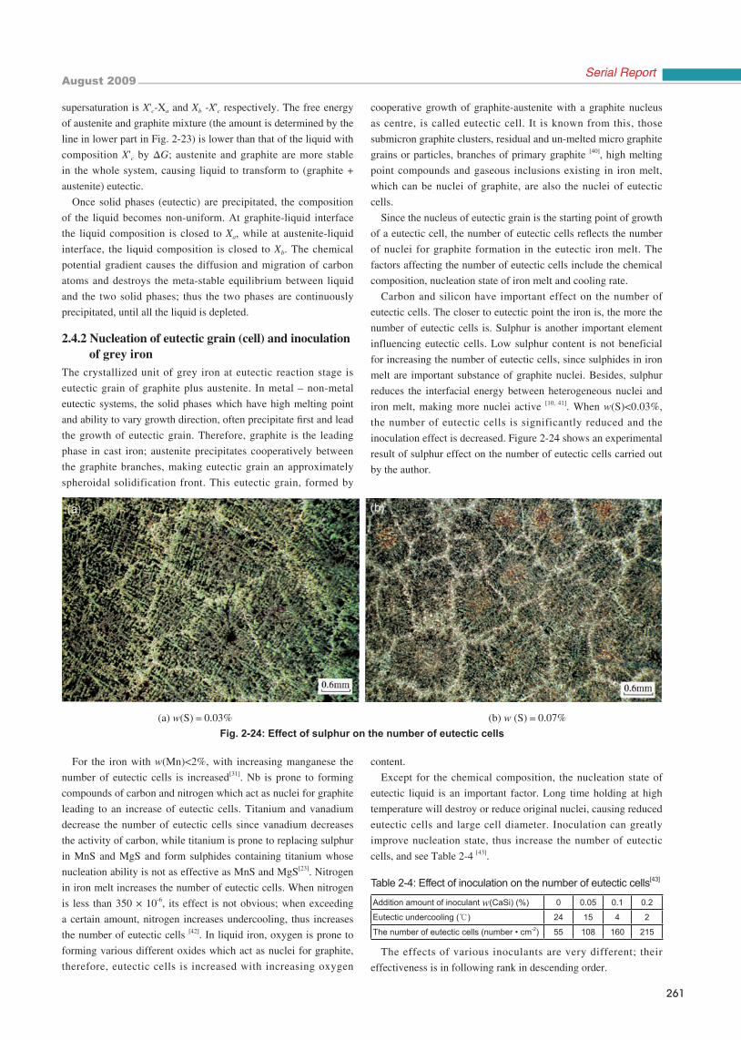
The amount and length of dendrites play a non-ignored role for
cast iron strength. The more the dendrite amount is, the stronger
the cast iron is. Figure 2-20 shows the relationship between tensile
strength and austenite dendrites [33]. The influence of secondary
axis spacing on cast iron property is not as significant as that of
the dendrite amount; nevertheless, with decrease of the secondary
axis spacing, the tensile strength also increases [34] and this trend
is decreased with increase of carbon equivalent. If dendrites are
presented as short, small and isolated forms in cast iron structure,
the improvement in tensile strength is not significant. When
dendrites cross each other and form frames, the area of interaction
(b) w(Mn)=1.685%
Fig.2-19: Effect of Mn on austenite dendrite amount [31]
(a) w(Mn) = 0.825%
260
CHINA FOUNDRY Vol.6 No.3
is increased, which is significantly beneficial for strength
improvement [32].
The distribution, morphology and orientation of austenite are
closely related to crack propagation under load. Endogenous
primary austenite normally is small in diameter and randomly
orientated; thus the induced cracks have a long propagation
distance, therefore has stronger ability of loading [35].
The effect of austenite dendrites in enhancing strength is
to prevent crack propagation during fracture process; when
encountering dendrite, crack either changes propagation direction
or propagates along the outer edge of austenite [35, 36]. Figure 2-21
shows an unfractured structure observed by the author; it is seen
that the crack propagates along the outer edge of the dendrites.
With increasing propagation paths, the consumed energy is increased.
In addition, the three dimensional frame structures can inhibit stress
transferring from one eutectic cell to another cell [24, 37, 38]; There is
no graphite inside dendrites, so the metal inside dendrites is not
weakened, thus can prevent microcrack growth.
The relationship between the amount of primary austenite and
hardness shows a rule in which the more the austenite amount is,
the higher the Brinell hardness is. The reason is that the dendrite
amount is less, eutectic cells are inevitably increased. Large
amount of eutectic graphite causes hardness of metal matrix to
decrease.
2.4 Eutectic crystallization of grey cast ironWhen the temperature of iron melt is slightly below eutectic
temperature, eutectic crystallization occurs and the eutectic phases
consisting of graphite and austenite form. Based on the growth
relationship of the two phases, eutectic system can be classified
into three types: regular eutectic, irregular eutectic and divorced
eutectic (also called abnormal eutectic), as illustrated in Fig. 2-22.
(1) Regular eutectic: The two phases of eutectic grow with
the same velocity, thus, the solid-liquid interface at crystallization
front maintains approximately planar. The micro morphology of
regular eutectic can be lamellar, rod- or fabric-shaped. Part of
type D graphite and coral graphite in grey iron form mainly under
regular eutectic condition.
(2) Irregular eutectic: There exists temperature difference in
the front of the two phases; the difference, even it is very small,
can cause one phase leading the other phase to grow, therefore
forming a zigzag eutectic interface. The two phases of the eutectic
grow closely and cooperatively with each other.
When the two phases, flake graphite and austenite in grey iron
crystallise, graphite always is in a leading position and grows in
liquid phase; attaching to graphite, austenite nucleates and grows
afterwards, therefore belongs to irregular eutectic.
(3) Divorced eutectic: The two phases of divorced eutectic
form separately each other in site and time. The eutectic in
spheroidal graphite cast iron belongs to divorced eutectic.
2.4.1 Thermodynamics of eutectic crystallisationWhen the temperature of a liquid iron is below eutectic line E' C' F'(see Fig. 2-23) and decreases to T 1, the liquid with composition
X'c is supersaturated compared to both the two constituents. Their
Fig. 2-23: Thermodynamic potential curve of Fe-C eutectic crystallisation
Fig.2-20: Dendrite amount vs grey iron tensile strength
Fig. 2-21: Crack propagates along the outer edge of dendrites
Fig. 2-22: Classification of eutectic system
August 2009
261
Serial Report
supersaturation is X'c-Xa and Xb -X'c respectively. The free energy
of austenite and graphite mixture (the amount is determined by the
line in lower part in Fig. 2-23) is lower than that of the liquid with
composition X'c by ΔG; austenite and graphite are more stable
in the whole system, causing liquid to transform to (graphite +
austenite) eutectic.
Once solid phases (eutectic) are precipitated, the composition
of the liquid becomes non-uniform. At graphite-liquid interface
the liquid composition is closed to Xa, while at austenite-liquid
interface, the liquid composition is closed to Xb. The chemical
potential gradient causes the diffusion and migration of carbon
atoms and destroys the meta-stable equilibrium between liquid
and the two solid phases; thus the two phases are continuously
precipitated, until all the liquid is depleted.
2.4.2 Nucleation of eutectic grain (cell) and inoculation of grey ironThe crystallized unit of grey iron at eutectic reaction stage is
eutectic grain of graphite plus austenite. In metal – non-metal
eutectic systems, the solid phases which have high melting point
and ability to vary growth direction, often precipitate first and lead
the growth of eutectic grain. Therefore, graphite is the leading
phase in cast iron; austenite precipitates cooperatively between
the graphite branches, making eutectic grain an approximately
spheroidal solidification front. This eutectic grain, formed by
cooperative growth of graphite-austenite with a graphite nucleus
as centre, is called eutectic cell. It is known from this, those
submicron graphite clusters, residual and un-melted micro graphite
grains or particles, branches of primary graphite [40], high melting
point compounds and gaseous inclusions existing in iron melt,
which can be nuclei of graphite, are also the nuclei of eutectic
cells.
Since the nucleus of eutectic grain is the starting point of growth
of a eutectic cell, the number of eutectic cells reflects the number
of nuclei for graphite formation in the eutectic iron melt. The
factors affecting the number of eutectic cells include the chemical
composition, nucleation state of iron melt and cooling rate.
Carbon and silicon have important effect on the number of
eutectic cells. The closer to eutectic point the iron is, the more the
number of eutectic cells is. Sulphur is another important element
influencing eutectic cells. Low sulphur content is not beneficial
for increasing the number of eutectic cells, since sulphides in iron
melt are important substance of graphite nuclei. Besides, sulphur
reduces the interfacial energy between heterogeneous nuclei and
iron melt, making more nuclei active [10, 41]. When w(S)<0.03%,
the number of eutectic cells is significantly reduced and the
inoculation effect is decreased. Figure 2-24 shows an experimental
result of sulphur effect on the number of eutectic cells carried out
by the author.
For the iron with w(Mn)<2%, with increasing manganese the
number of eutectic cells is increased[31]. Nb is prone to forming
compounds of carbon and nitrogen which act as nuclei for graphite
leading to an increase of eutectic cells. Titanium and vanadium
decrease the number of eutectic cells since vanadium decreases
the activity of carbon, while titanium is prone to replacing sulphur
in MnS and MgS and form sulphides containing titanium whose
nucleation ability is not as effective as MnS and MgS[23]. Nitrogen
in iron melt increases the number of eutectic cells. When nitrogen
is less than 350 × 10-6, its effect is not obvious; when exceeding
a certain amount, nitrogen increases undercooling, thus increases
the number of eutectic cells [42]. In liquid iron, oxygen is prone to
forming various different oxides which act as nuclei for graphite,
therefore, eutectic cells is increased with increasing oxygen
content.
Except for the chemical composition, the nucleation state of
eutectic liquid is an important factor. Long time holding at high
temperature will destroy or reduce original nuclei, causing reduced
eutectic cells and large cell diameter. Inoculation can greatly
improve nucleation state, thus increase the number of eutectic
cells, and see Table 2-4 [43].
Addition amount of inoculant w(CaSi) (%) 0 0.05 0.1 0.2
Eutectic undercooling (℃) 24 15 4 2
The number of eutectic cells (number • cm-2) 55 108 160 215
The effects of various inoculants are very different; their
effectiveness is in following rank in descending order.
(a) w(S)=0.03% (b) w (S)=0.07%Fig. 2-24: Effect of sulphur on the number of eutectic cells
Table 2-4: Effect of inoculation on the number of eutectic cells[43]
262
CHINA FOUNDRY Vol.6 No.3
CaSi>ZrFeSi>75FeSi>BaSi>SrFeSi
FeSi with Sr or Ti has weaker influence on the number of
eutectic cells, while the inoculants with rare earth have the much
better effectiveness; when adding with Al and N, the effect is
even more remarkable [32]. The author found from experiments
Cooling rate has significant influence on the number of eutectic
cells; the fast the cooling, the more the amount of eutectic cells,
see Table 2-5.
Comparing the numbers of Table 2-4 and 2-5, it is seen that
inoculation decreases undercooling, while fast cooling rate
increases undercooling. Nevertheless, both of them obviously
increase the number of eutectic cells, indicating that undercooling
has double effects on eutectic cells.
The amount of eutectic cells directly reflects the refinement
of eutectic grains. According to general rule, fine grains can
increase the property of metal. For a long time, when discussing
the relationship between strength and eutectic cells of grey iron,
it is considered that under the premise of similar composition
and graphite types, tensile strength increases with increasing
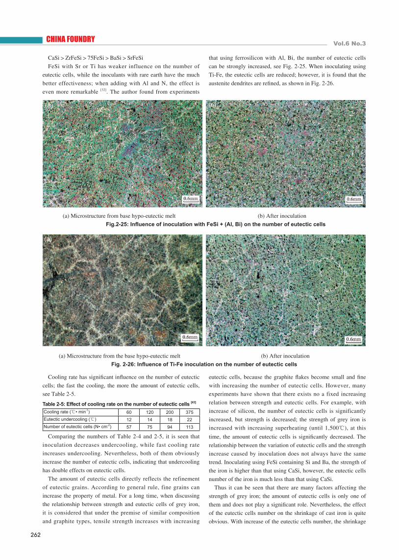
that using ferrosilicon with Al, Bi, the number of eutectic cells
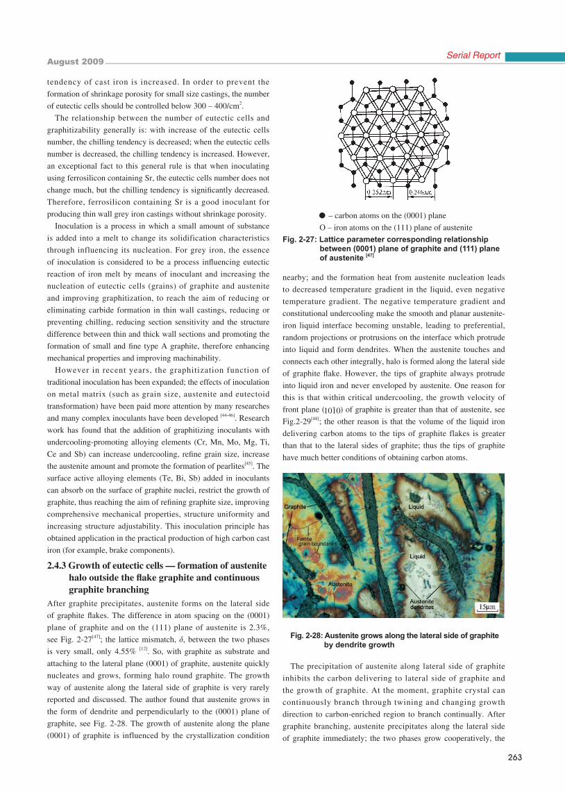
can be strongly increased, see Fig. 2-25. When inoculating using
Ti-Fe, the eutectic cells are reduced; however, it is found that the
austenite dendrites are refined, as shown in Fig. 2-26.
(a) Microstructure from base hypo-eutectic melt (b) After inoculation Fig.2-25: Influence of inoculation with FeSi + (Al, Bi) on the number of eutectic cells
(a) Microstructure from the base hypo-eutectic melt (b) After inoculationFig. 2-26: Influence of Ti-Fe inoculation on the number of eutectic cells
eutectic cells, because the graphite flakes become small and fine
with increasing the number of eutectic cells. However, many
experiments have shown that there exists no a fixed increasing
relation between strength and eutectic cells. For example, with
increase of silicon, the number of eutectic cells is significantly
increased, but strength is decreased; the strength of grey iron is
increased with increasing superheating (until 1,500℃), at this
time, the amount of eutectic cells is significantly decreased. The
relationship between the variation of eutectic cells and the strength
increase caused by inoculation does not always have the same
trend. Inoculating using FeSi containing Si and Ba, the strength of
the iron is higher than that using CaSi, however, the eutectic cells
number of the iron is much less than that using CaSi.
Thus it can be seen that there are many factors affecting the
strength of grey iron; the amount of eutectic cells is only one of
them and does not play a significant role. Nevertheless, the effect
of the eutectic cells number on the shrinkage of cast iron is quite
obvious. With increase of the eutectic cells number, the shrinkage
Cooling rate (℃• min-1) 60 120 200 375Eutectic undercooling (℃) 12 14 18 22Number of eutectic cells (N• cm-2) 57 75 94 113
Table 2-5: Effect of cooling rate on the number of eutectic cells [43]
August 2009
263
Serial Report
nearby; and the formation heat from austenite nucleation leads
to decreased temperature gradient in the liquid, even negative
temperature gradient. The negative temperature gradient and
constitutional undercooling make the smooth and planar austenite-
iron liquid interface becoming unstable, leading to preferential,
random projections or protrusions on the interface which protrude
into liquid and form dendrites. When the austenite touches and
connects each other integrally, halo is formed along the lateral side
of graphite flake. However, the tips of graphite always protrude
into liquid iron and never enveloped by austenite. One reason for
this is that within critical undercooling, the growth velocity of
front plane ( ) of graphite is greater than that of austenite, see
Fig.2-29[48]; the other reason is that the volume of the liquid iron
delivering carbon atoms to the tips of graphite flakes is greater
than that to the lateral sides of graphite; thus the tips of graphite
have much better conditions of obtaining carbon atoms.
Fig. 2-28: Austenite grows along the lateral side of graphite by dendrite growth
The precipitation of austenite along lateral side of graphite
inhibits the carbon delivering to lateral side of graphite and
the growth of graphite. At the moment, graphite crystal can
continuously branch through twining and changing growth
direction to carbon-enriched region to branch continually. After
graphite branching, austenite precipitates along the lateral side
of graphite immediately; the two phases grow cooperatively, the
tendency of cast iron is increased. In order to prevent the
formation of shrinkage porosity for small size castings, the number
of eutectic cells should be controlled below 300 – 400/cm2.
The relationship between the number of eutectic cells and
graphitizability generally is: with increase of the eutectic cells
number, the chilling tendency is decreased; when the eutectic cells
number is decreased, the chilling tendency is increased. However,
an exceptional fact to this general rule is that when inoculating
using ferrosilicon containing Sr, the eutectic cells number does not
change much, but the chilling tendency is significantly decreased.
Therefore, ferrosilicon containing Sr is a good inoculant for
producing thin wall grey iron castings without shrinkage porosity.
Inoculation is a process in which a small amount of substance
is added into a melt to change its solidification characteristics
through influencing its nucleation. For grey iron, the essence
of inoculation is considered to be a process influencing eutectic
reaction of iron melt by means of inoculant and increasing the
nucleation of eutectic cells (grains) of graphite and austenite
and improving graphitization, to reach the aim of reducing or
eliminating carbide formation in thin wall castings, reducing or
preventing chilling, reducing section sensitivity and the structure
difference between thin and thick wall sections and promoting the
formation of small and fine type A graphite, therefore enhancing
mechanical properties and improving machinability.
However in recent years, the graphitization function of
traditional inoculation has been expanded; the effects of inoculation
on metal matrix (such as grain size, austenite and eutectoid
transformation) have been paid more attention by many researches
and many complex inoculants have been developed [44-46]. Research
work has found that the addition of graphitizing inoculants with
undercooling-promoting alloying elements (Cr, Mn, Mo, Mg, Ti,
Ce and Sb) can increase undercooling, refine grain size, increase
the austenite amount and promote the formation of pearlites[45]. The
surface active alloying elements (Te, Bi, Sb) added in inoculants
can absorb on the surface of graphite nuclei, restrict the growth of
graphite, thus reaching the aim of refining graphite size, improving
comprehensive mechanical properties, structure uniformity and
increasing structure adjustability. This inoculation principle has
obtained application in the practical production of high carbon cast
iron (for example, brake components).
2.4.3 Growth of eutectic cells – formation of austenite halo outside the flake graphite and continuous graphite branching After graphite precipitates, austenite forms on the lateral side
of graphite flakes. The difference in atom spacing on the (0001)
plane of graphite and on the (111) plane of austenite is 2.3%,
see Fig. 2-27[47]; the lattice mismatch, δ, between the two phases
is very small, only 4.55% [12]. So, with graphite as substrate and
attaching to the lateral plane (0001) of graphite, austenite quickly
nucleates and grows, forming halo round graphite. The growth
way of austenite along the lateral side of graphite is very rarely
reported and discussed. The author found that austenite grows in
the form of dendrite and perpendicularly to the (0001) plane of
graphite, see Fig. 2-28. The growth of austenite along the plane
(0001) of graphite is influenced by the crystallization condition
● – carbon atoms on the (0001) plane
O – iron atoms on the (111) plane of austeniteFig. 2-27: Lattice parameter corresponding relationship between (0001) plane of graphite and (111) plane of austenite [47]
264
CHINA FOUNDRY Vol.6 No.3
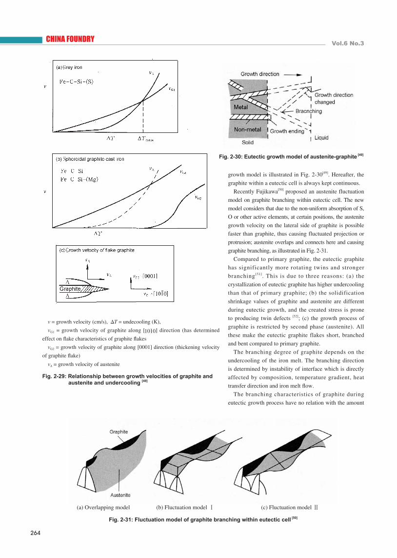
v = growth velocity (cm/s), ΔT = undecooling (K),
vG1 = growth velocity of graphite along [ ] direction (has determined
effect on flake characteristics of graphite flakes
vG2 = growth velocity of graphite along [0001] direction (thickening velocity
of graphite flake)
vA = growth velocity of austenite
Fig. 2-29: Relationship between growth velocities of graphite and austenite and undercooling [48]
growth model is illustrated in Fig. 2-30[49]. Hereafter, the
graphite within a eutectic cell is always kept continuous.
Recently Fujikawa[50] proposed an austenite fluctuation
model on graphite branching within eutectic cell. The new
model considers that due to the non-uniform absorption of S,
O or other active elements, at certain positions, the austenite
growth velocity on the lateral side of graphite is possible
faster than graphite, thus causing fluctuated projection or
protrusion; austenite overlaps and connects here and causing
graphite branching, as illustrated in Fig. 2-31.
Compared to primary graphite, the eutectic graphite
has significantly more rotating twins and stronger
branching[51]. This is due to three reasons: (a) the
crystallization of eutectic graphite has higher undercooling
than that of primary graphite; (b) the solidification
shrinkage values of graphite and austenite are different
during eutectic growth, and the created stress is prone
to producing twin defects [52]; (c) the growth process of
graphite is restricted by second phase (austenite). All
these make the eutectic graphite flakes short, branched
and bent compared to primary graphite.
The branching degree of graphite depends on the
undercooling of the iron melt. The branching direction
is determined by instability of interface which is directly
affected by composition, temperature gradient, heat
transfer direction and iron melt flow.
The branching characteristics of graphite during
eutectic growth process have no relation with the amount
Fig. 2-31: Fluctuation model of graphite branching within eutectic cell [50]
Fig. 2-30: Eutectic growth model of austenite-graphite [49]
(a) Overlapping model (b) Fluctuation model Ⅰ (c) Fluctuation model Ⅱ
August 2009
265
Serial Report
various interface shapes are related to branching degree of
graphite[42], the frequency (or severity) of branching is directly
influenced by undercooling.
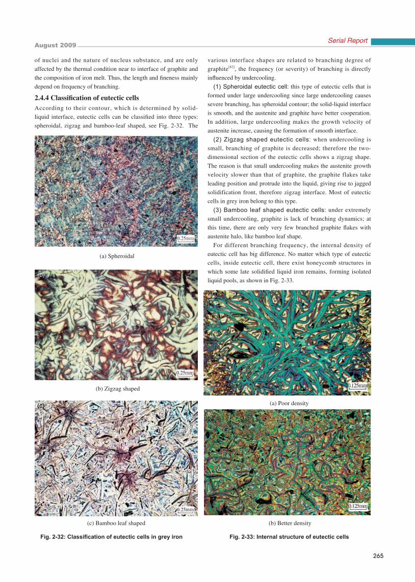
(1) Spheroidal eutectic cell: this type of eutectic cells that is
formed under large undercooling since large undercooling causes
severe branching, has spheroidal contour; the solid-liquid interface
is smooth, and the austenite and graphite have better cooperation.
In addition, large undercooling makes the growth velocity of
austenite increase, causing the formation of smooth interface.
(2) Zigzag shaped eutectic cells: when undercooling is
small, branching of graphite is decreased; therefore the two-
dimensional section of the eutectic cells shows a zigzag shape.
The reason is that small undercooling makes the austenite growth
velocity slower than that of graphite, the graphite flakes take
leading position and protrude into the liquid, giving rise to jagged
solidification front, therefore zigzag interface. Most of eutectic
cells in grey iron belong to this type.
(3) Bamboo leaf shaped eutectic cells: under extremely
small undercooling, graphite is lack of branching dynamics; at
this time, there are only very few branched graphite flakes with
austenite halo, like bamboo leaf shape.
For different branching frequency, the internal density of
eutectic cell has big difference. No matter which type of eutectic
cells, inside eutectic cell, there exist honeycomb structures in
which some late solidified liquid iron remains, forming isolated
liquid pools, as shown in Fig. 2-33.
of nuclei and the nature of nucleus substance, and are only
affected by the thermal condition near to interface of graphite and
the composition of iron melt. Thus, the length and fineness mainly
depend on frequency of branching.
2.4.4 Classification of eutectic cellsAccording to their contour, which is determined by solid-
liquid interface, eutectic cells can be classified into three types:
spheroidal, zigzag and bamboo-leaf shaped, see Fig. 2-32. The
Fig. 2-32: Classification of eutectic cells in grey iron
(c) Bamboo leaf shaped
Fig. 2-33: Internal structure of eutectic cells
(a) Spheroidal
(b) Zigzag shaped
(a) Poor density
(b) Better density
266
CHINA FOUNDRY Vol.6 No.3
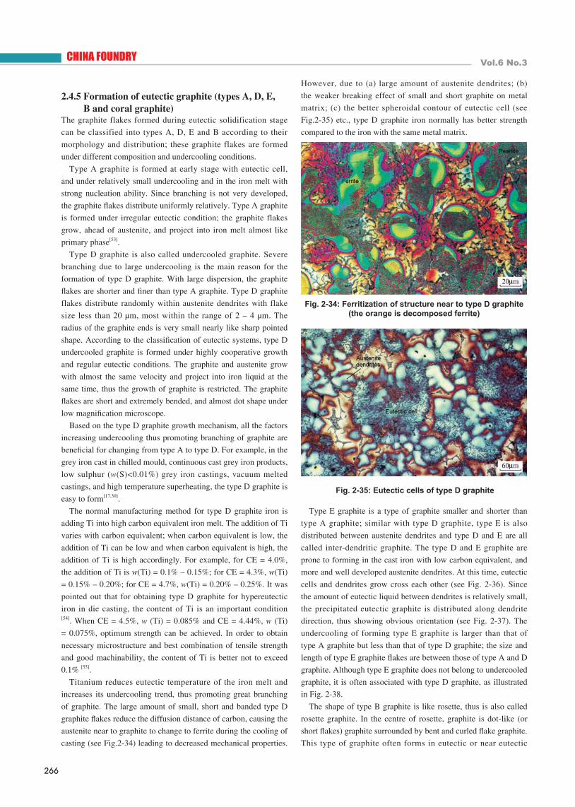
However, due to (a) large amount of austenite dendrites; (b)
the weaker breaking effect of small and short graphite on metal
matrix; (c) the better spheroidal contour of eutectic cell (see
Fig.2-35) etc., type D graphite iron normally has better strength
compared to the iron with the same metal matrix.
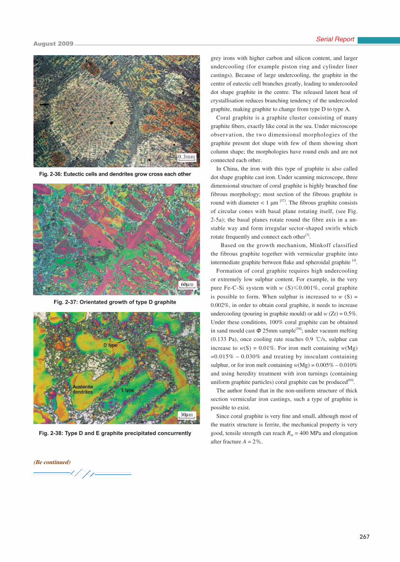
Type E graphite is a type of graphite smaller and shorter than
type A graphite; similar with type D graphite, type E is also
distributed between austenite dendrites and type D and E are all
called inter-dendritic graphite. The type D and E graphite are
prone to forming in the cast iron with low carbon equivalent, and
more and well developed austenite dendrites. At this time, eutectic
cells and dendrites grow cross each other (see Fig. 2-36). Since
the amount of eutectic liquid between dendrites is relatively small,
the precipitated eutectic graphite is distributed along dendrite
direction, thus showing obvious orientation (see Fig. 2-37). The
undercooling of forming type E graphite is larger than that of
type A graphite but less than that of type D graphite; the size and
length of type E graphite flakes are between those of type A and D
graphite. Although type E graphite does not belong to undercooled
graphite, it is often associated with type D graphite, as illustrated
in Fig. 2-38.
The shape of type B graphite is like rosette, thus is also called
rosette graphite. In the centre of rosette, graphite is dot-like (or
short flakes) graphite surrounded by bent and curled flake graphite.
This type of graphite often forms in eutectic or near eutectic
Fig. 2-34: Ferritization of structure near to type D graphite (the orange is decomposed ferrite)
2.4.5 Formation of eutectic graphite (types A, D, E, B and coral graphite) The graphite flakes formed during eutectic solidification stage
can be classified into types A, D, E and B according to their
morphology and distribution; these graphite flakes are formed
under different composition and undercooling conditions.
Type A graphite is formed at early stage with eutectic cell,
and under relatively small undercooling and in the iron melt with
strong nucleation ability. Since branching is not very developed,
the graphite flakes distribute uniformly relatively. Type A graphite
is formed under irregular eutectic condition; the graphite flakes
grow, ahead of austenite, and project into iron melt almost like
primary phase[53].
Type D graphite is also called undercooled graphite. Severe
branching due to large undercooling is the main reason for the
formation of type D graphite. With large dispersion, the graphite
flakes are shorter and finer than type A graphite. Type D graphite
flakes distribute randomly within austenite dendrites with flake
size less than 20 µm, most within the range of 2 – 4 µm. The
radius of the graphite ends is very small nearly like sharp pointed
shape. According to the classification of eutectic systems, type D
undercooled graphite is formed under highly cooperative growth
and regular eutectic conditions. The graphite and austenite grow
with almost the same velocity and project into iron liquid at the
same time, thus the growth of graphite is restricted. The graphite
flakes are short and extremely bended, and almost dot shape under
low magnification microscope.
Based on the type D graphite growth mechanism, all the factors
increasing undercooling thus promoting branching of graphite are
beneficial for changing from type A to type D. For example, in the
grey iron cast in chilled mould, continuous cast grey iron products,
low sulphur (w(S)<0.01%) grey iron castings, vacuum melted
castings, and high temperature superheating, the type D graphite is
easy to form[17,30].
The normal manufacturing method for type D graphite iron is
adding Ti into high carbon equivalent iron melt. The addition of Ti
varies with carbon equivalent; when carbon equivalent is low, the
addition of Ti can be low and when carbon equivalent is high, the
addition of Ti is high accordingly. For example, for CE = 4.0%,
the addition of Ti is w(Ti) = 0.1% – 0.15%; for CE = 4.3%, w(Ti)
= 0.15% – 0.20%; for CE = 4.7%, w(Ti) = 0.20% – 0.25%. It was
pointed out that for obtaining type D graphite for hypereutectic
iron in die casting, the content of Ti is an important condition [54]. When CE = 4.5%, w (Ti) = 0.085% and CE = 4.44%, w (Ti)
= 0.075%, optimum strength can be achieved. In order to obtain
necessary microstructure and best combination of tensile strength
and good machinability, the content of Ti is better not to exceed
0.1% [55].
Titanium reduces eutectic temperature of the iron melt and
increases its undercooling trend, thus promoting great branching
of graphite. The large amount of small, short and banded type D
graphite flakes reduce the diffusion distance of carbon, causing the
austenite near to graphite to change to ferrite during the cooling of
casting (see Fig.2-34) leading to decreased mechanical properties.
Fig. 2-35: Eutectic cells of type D graphite
August 2009
267
Serial Report
Fig. 2-36: Eutectic cells and dendrites grow cross each other
Fig. 2-37: Orientated growth of type D graphite
Fig. 2-38: Type D and E graphite precipitated concurrently
grey irons with higher carbon and silicon content, and larger
undercooling (for example piston ring and cylinder liner
castings). Because of large undercooling, the graphite in the
centre of eutectic cell branches greatly, leading to undercooled
dot shape graphite in the centre. The released latent heat of
crystallisation reduces branching tendency of the undercooled
graphite, making graphite to change from type D to type A.
Coral graphite is a graphite cluster consisting of many
graphite fibers, exactly like coral in the sea. Under microscope
observation, the two dimensional morphologies of the
graphite present dot shape with few of them showing short
column shape; the morphologies have round ends and are not
connected each other.
In China, the iron with this type of graphite is also called
dot shape graphite cast iron. Under scanning microscope, three
dimensional structure of coral graphite is highly branched fine
fibrous morphology; most section of the fibrous graphite is
round with diameter < 1 µm [57]. The fibrous graphite consists
of circular cones with basal plane rotating itself, (see Fig.
2-5a); the basal planes rotate round the fibre axis in a un-
stable way and form irregular sector-shaped swirls which
rotate frequently and connect each other[3].
Based on the growth mechanism, Minkoff classified
the fibrous graphite together with vermicular graphite into
intermediate graphite between flake and spheroidal graphite [4].
Formation of coral graphite requires high undercooling
or extremely low sulphur content. For example, in the very
pure Fe-C-Si system with w (S)≤0.001%, coral graphite
is possible to form. When sulphur is increased to w (S) =
0.002%, in order to obtain coral graphite, it needs to increase
undercooling (pouring in graphite mould) or add w (Zr) = 0.5%.
Under these conditions, 100% coral graphite can be obtained
in sand mould cast Φ 25mm sample[58]; under vacuum melting
(0.133 Pa), once cooling rate reaches 0.9 ℃/s, sulphur can
increase to w(S) = 0.01%. For iron melt containing w(Mg)
=0.015% – 0.030% and treating by inoculant containing
sulphur, or for iron melt containing w(Mg) = 0.005% – 0.010%
and using heredity treatment with iron turnings (containing
uniform graphite particles) coral graphite can be produced[60].
The author found that in the non-uniform structure of thick
section vermicular iron castings, such a type of graphite is
possible to exist.
Since coral graphite is very fine and small, although most of
the matrix structure is ferrite, the mechanical property is very
good, tensile strength can reach Rm = 400 MPa and elongation
after fracture A = 2%.
(Be continued)

![Colour Metallography of Cast Iron - foundryworld.com · Fig. 2-49: Vertical section of stable and meta-stable Fe-C-P systems (the dash line is with addition of Te) [61] (a) Meniscus](https://img.pdfslide.us/doc/110x75/5c5bff1909d3f259368cb1d6/colour-metallography-of-cast-iron-fig-2-49-vertical-section-of-stable-and.jpg)