Embed Size (px)
Citation preview

Colour Histograms as Background Description:An approach to overcoming the Uniform-Goal
Problem within the SPL for theRoboCup WC 2012
Markus Bader1, Helmut Brunner1, Thomas Hambock1, andAlexander Hofmann2 and Markus Vincze1
1Automation and Control Institute (ACIN), Vienna University of TechnologyGusshausstrasse 27-29 / E376, A-1040 Vienna, Austria
{markus.bader,helmut.brunner,
thomas.hamboeck,markus.vincze}@tuwien.ac.at
http://www.acin.tuwien.ac.at2Institute of Computer Science, University of Applied Sciences Technikum Wien
Hoechstaedtplatz 5, A-1200 Vienna, [email protected]
http://www.technikum-wien.at
Abstract. Recent rule changes in the RoboCup SPL (Standard Plat-form League) have resulted in a challenge to making goals uniform. Par-ticipating teams must now keep track of their playing direction duringthe game. This poses a problem since the robots allowed are not equippedwith an electronic compass.This paper presents a novel idea: Usage of the visual background that isnormally removed as an additional clue for robot localization. Multiplecolour histograms are used to describe the background in different ar-eas in order to overcome the uniform goal problem. The paper presentsfirst approaches of the Austrian-Kangaroos RoboCup Team with somepreliminary results and will give the reader some insight as to how theongoing work in this research area has progressed.
Keywords: Localization, RoboCup, Computer Vision, Robotics, Back-ground, Colour Histogram
1 Introduction
Removing or segmenting the background from objects of interest is the mostcommon first step of a computer vision system. This allows the computationalresources to focus on the area of interest.A specific approach are employed in the RoboCup SPL (Standard PlatformLeague): Fast, internal angular sensors next to the camera are used by mostteams to find and project the horizon in the camera image. Computational cheapvision algorithms are then used to predict a convex hull around the green play-ground in which all objects of interest are assumed [1, 2, 3]. But more recently,

2 M. Bader, H. Brunner, T. Hambock, A. Hofmann and M. Vincze
rule changes within the league are forcing teams to also consider the surroundingwhen monitoring the playing direction. This season, keeping goals uniform is themost dominant problem since the playground is fully symmetric and no artifi-cial landmarks are allowed to determine the playing direction. In addition, therobotic hardware used does not include any internal sensors including an elec-tronic compass, which is used in the middle size league to estimate the playingdirection. Therefore, the system has to keep track of the surrounding environ-ment in order to prevent own goals.The league has to switch from a classical localization algorithm to SLAM (SelfLocalization and Mapping) approaches [4]. This paper presents a method for de-termining the correct direction by segmenting the background into equally sized,projected tiles and uses their colour histograms in order to distinguish the tiles.The matching algorithm is similar to algorithms that are used in stereo visionsystems to compare observed tiles with the background previously observed andlearned. Our tests on real and simulated data shows that this approach will notsolve the localization problem, but it is sufficient to find the playing direction.Fig. 1 shows a simulated robot and projected tiles in two different but similarlocations.This paper is structured as follows: First, we give a brief introduction to the
background needed to understand our approach. Then Section 3 presents otherapproaches to the uniform goal challenge and a similar method used for robotlocalization. Finally, Section 4 describes our approach followed by preliminaryresults and a conclusion in Section 6.
2 Background and Self-Localization
Commonly used localization techniques are based on particle filters [4] and/orKalman filters like those in [5, 6]. Both techniques are designed to estimate asystem’s state x at a creation time. Such an estimated xt is based on a mea-surement yt related to the state by the function h and on a state prediction xt.The state prediction involves knowledge of the system F as well as the controlcommands u. Since we are dealing with a real system, we have to integrate themeasurement noise v and disturbances on our model w. Therefore, we preferrewriting the classical form of a Filter [7] to Eq. (1).
xt = F (xt, yt, vt) state estimate (1a)
yt = h(xt, wt, vt) measurement prediction (1b)
xt = F (xt−1, ut−1, wt−1) state prediction (1c)
A particle filter generates state hypothesis called particles with a predictedmeasurement yt. Good particles with a yt near the perceived measurement yt areupdated by F for the next measurement comparison. Particles with a bad yt arere-sampled on locations near the good particles and updated by F afterwards.
Colour Histograms as Background Description 3
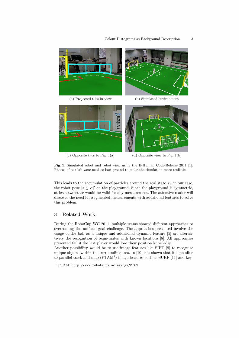
(a) Projected tiles in view (b) Simulated environment
(c) Opposite tiles to Fig. 1(a) (d) Opposite view to Fig. 1(b)
Fig. 1. Simulated robot and robot view using the B-Human Code-Release 2011 [1].Photos of our lab were used as background to make the simulation more realistic.
This leads to the accumulation of particles around the real state xt, in our case,the robot pose [x, y, α]′ on the playground. Since the playground is symmetric,at least two state would be valid for any measurement. The attentive reader willdiscover the need for augmented measurements with additional features to solvethis problem.
3 Related Work
During the RoboCup WC 2011, multiple teams showed different approaches toovercoming the uniform goal challenge. The approaches presented involve theusage of the ball as a unique and additional dynamic feature [5] or, alterna-tively the recognition of team-mates with known locations [8]. All approachespresented fail if the last player would lose their position knowledge.Another possibility would be to use image features like SIFT [9] to recognizeunique objects within the surrounding area. In [10] it is shown that it is possibleto parallel track and map (PTAM1) image features such as SURF [11] and key-
1 PTAM: http://www.robots.ox.ac.uk/~gk/PTAM
4 M. Bader, H. Brunner, T. Hambock, A. Hofmann and M. Vincze
points to estimate a camera pose in real-time. This was possible by optimizedimplementations of the 5-point pose estimation algorithm [12, 13]. But this al-gorithm would consume all of the computational power on our robot hardwarethat is needed by other components.A computationally more efficient method that is more related to the work pre-sented was proposed by [14] that used colour histograms derived by an omnidi-rectional camera to recognize environments. This approach was also not sufficientto estimate the robot’s exact pose but enabled the system to estimate the roomin which the robot was located and to load the correct, pre-known map for theactual localization.
4 Colour histogram based orientation estimation
Our approach extends the particle filter used by an additional measurement tofavour particles with a certain orientation α. This is done by:
1. Projecting tiles onto a virtual surrounding wall.2. Calculating colour histograms of each tile.3. Matching the perceived colour histograms against the knowledge base.4. Updating the knowledge base if possible.
4.1 Background tiles and segmentation
The first step in our approach is to segment the background into tiles by project-ing rectangles on a virtual wall next to the playground. This can be done sincethe localization converges into two maxima with different signs. The projectedtiles will be on the same projected image location in both cases see Fig. 1. Tilesthat are not completely in the current view are not taken into account.It would also be possible to project tiles in more than one row or even onto theceiling, if needed. It should also be mentioned that the position of the tiles couldbe adapted, and it could also be designed to create a dome to cover the entiresurrounding area.
4.2 Histogram
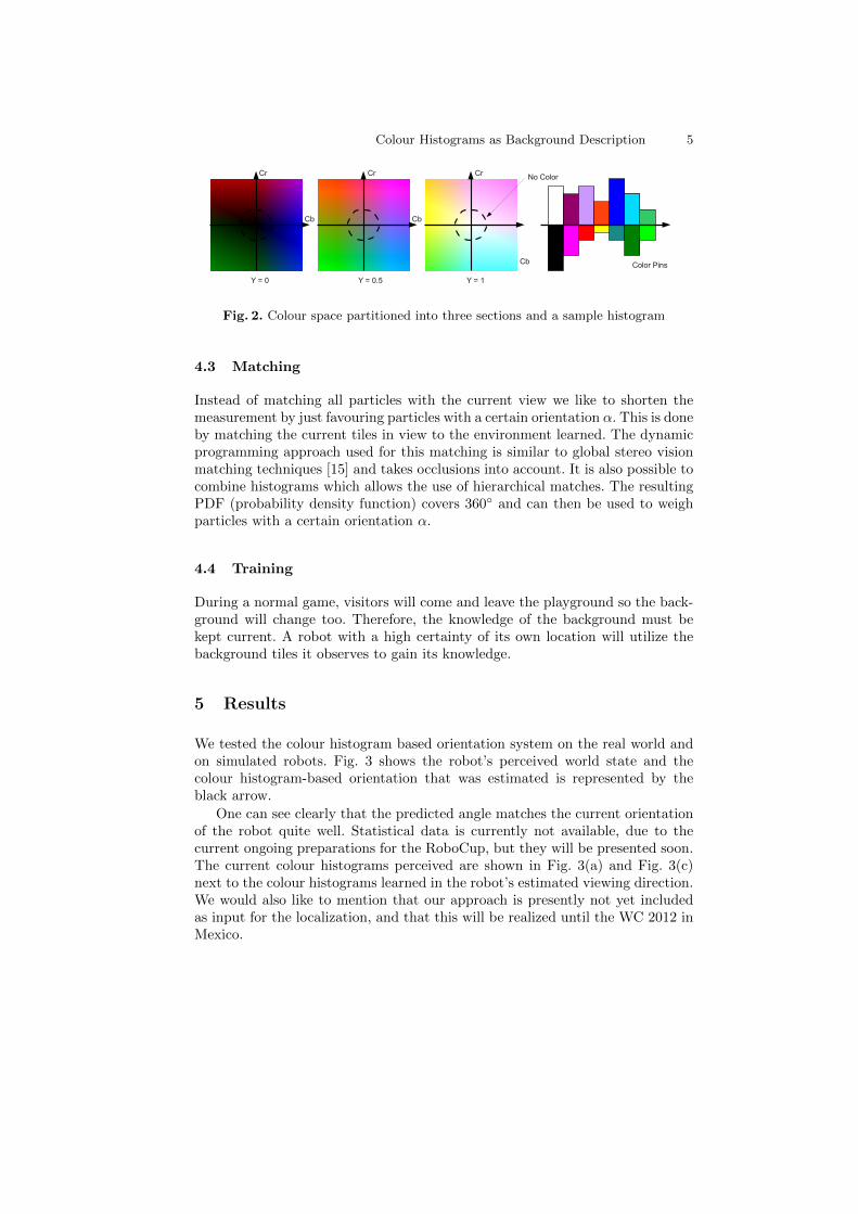
Our colour histogram has 14 pins, 12 for colours and two representing the blackand white components in the yCbCr colour representation. An inner cylinderalong the y-axis is used for the black and white components and the remainingspace is partitioned into three levels where every level is divided into four colourclasses. With this approach, it is sufficient to compare the signs of the Cb and Cr
components to determine the colour class. Fig. 2 shows the colour space and asample histogram. The circle in the colour space represents the area mapped inblack and white. The layer where y = 0 is the first layer (dark colours), y = 0.5is the second layer and at y = 1 shows the third layer (light colours).
Colour Histograms as Background Description 5
Cr
Cb
Cr
Cb
Cb
Cr
Y = 0 Y = 0.5 Y = 1
Color Pins
No Color
Fig. 2. Colour space partitioned into three sections and a sample histogram
4.3 Matching
Instead of matching all particles with the current view we like to shorten themeasurement by just favouring particles with a certain orientation α. This is doneby matching the current tiles in view to the environment learned. The dynamicprogramming approach used for this matching is similar to global stereo visionmatching techniques [15] and takes occlusions into account. It is also possible tocombine histograms which allows the use of hierarchical matches. The resultingPDF (probability density function) covers 360◦ and can then be used to weighparticles with a certain orientation α.
4.4 Training
During a normal game, visitors will come and leave the playground so the back-ground will change too. Therefore, the knowledge of the background must bekept current. A robot with a high certainty of its own location will utilize thebackground tiles it observes to gain its knowledge.
5 Results
We tested the colour histogram based orientation system on the real world andon simulated robots. Fig. 3 shows the robot’s perceived world state and thecolour histogram-based orientation that was estimated is represented by theblack arrow.
One can see clearly that the predicted angle matches the current orientationof the robot quite well. Statistical data is currently not available, due to thecurrent ongoing preparations for the RoboCup, but they will be presented soon.The current colour histograms perceived are shown in Fig. 3(a) and Fig. 3(c)next to the colour histograms learned in the robot’s estimated viewing direction.We would also like to mention that our approach is presently not yet includedas input for the localization, and that this will be realized until the WC 2012 inMexico.

6 M. Bader, H. Brunner, T. Hambock, A. Hofmann and M. Vincze
(a) Simulated robots, world state (b) Simulated robot and its current viewrelated to (a)
(c) Real robot, world state (d) Real robot view related to (c)
Fig. 3. Simulated and real robot with drawn estimated viewing direction based on thecolour histogram approach, the real robot world state (c) includes also the currentpredicted location.
6 Conclusion
We have presented a novel way of using multiple colour histograms as an addi-tional source of clues for particle localization. Colour histograms are based onwall tiles projected into the image that cover the surrounding area. The pro-posed matching algorithm provides a PDF of 360◦ which is used to augment thecurrent measurement. A particle filter can use the result to favour particles witha certain orientation. The preliminary results on simulated and real data thatwere presented showed the first signs of success, but these also open up issuesconcerning matching and learning techniques. The approach presented can berun in real-time on a NAO robot. Enhancement of the processes of on distribut-ing and finding a common background during the game will still be an opentopic for more research. Finally, we like to mention that the colour histogrambased orientation estimation can also be of use in other mobile robotics topicsnext to RoboCup.

Bibliography
[1] Thomas Rofer, Tim Laue, Judith Muller, Alexander Fabisch, Fynn Feld-pausch, Katharina Gillmann, Colin Graf, Thijs Jeffry de Haas, Alexan-der Hartl, Arne Humann, Daniel Honsel, Philipp Kastner, Tobias Kastner,Carsten Konemann, Benjamin Markowsky, Ole Jan Lars Riemann, and FelixWenk. B-human team report and code release 2011, 2011. Only available on-line: http://www.b-human.de/downloads/bhuman11_coderelease.pdf.
[2] Markus Bader, Alexander Hofmann, Jens Knoop, Bernhard Miller, Diet-mar Schreiner, and Markus Vincze. Austrian-kangaroos team descriptionfor robocup 2011. In RoboCup 2011: Robot Soccer World Cup XV Prepro-ceedings. RoboCup Federation, 2011.
[3] Somchaya Liemhetcharat, Brian Coltin, Junyun Tay, and Manuela Veloso.Cmurfs 11: Carnegie mellon united robots for soccer. In Thomas Rofer,Norbert Michael Mayer, Jesus Savage, and Uluc Saranli, editors, RoboCup2011: Robot Soccer World Cup XV Preproceedings. RoboCup Federation,2011.
[4] Sebastian Thrun, Wolfram Burgard, and Dieter Fox. Probabilistic Robotics(Intelligent Robotics and Autonomous Agents). The MIT Press, 2005.
[5] Matthias Hofmann, Soren Kerner, Ingmar Schwarz, Stefan Tasse, and OliverUrbann. Nao devils dortmund team description for robocup 2011. InRoboCup 2011: Robot Soccer World Cup XV Preproceedings. RoboCup Fed-eration, 2011.
[6] Rick Middleton. Nuim team description for 2011 robocup standard platformleague - nao roboeireann. In RoboCup 2011: Robot Soccer World Cup XVPreproceedings. RoboCup Federation, 2011.
[7] Wolfgang Kemmetmueller and Andreas Kugi. Prozessidentifikation, 2011.[8] B-Human. Description of open challenge 2011 demonstration, playing soccer
on a field without unique goals, June 2011. RoboCup WC.[9] David G. Lowe. Distinctive image features from scale-invariant keypoints.
Int. J. Comput. Vision, 60(2):91–110, 2004.[10] David Nister. An efficient solution to the five-point relative pose problem.
IEEE Trans. Pattern Anal. Mach. Intell., 26:756–777, June 2004.[11] Herbert Bay, Tinne Tuytelaars, and Luc Van Gool. Surf: Speeded up robust
features. In Ales Leonardis, Horst Bischof, and Axel Pinz, editors, ComputerVision – ECCV 2006, volume 3951 of Lecture Notes in Computer Science,pages 404–417. Springer Berlin / Heidelberg, 2006.
[12] E. Kruppa. Zur ermittlung eines objektes aus zwei perspektiven mit innererorientierung. Other Journal, pages 1939–1948, 1913.
[13] Henrik Stewenius, Christopher Engels, and David Nister. Recent develop-ments on direct relative orientation. ISPRS Journal of Photogrammetryand Remote Sensing, 60(4):284–294, 2006.
[14] P. Blaer and P. Allen. Topological mobile robot localization using fastvision techniques. In Robotics and Automation, 2002. Proceedings. ICRA

8 M. Bader, H. Brunner, T. Hambock, A. Hofmann and M. Vincze
’02. IEEE International Conference on, volume 1, pages 1031 – 1036 vol.1,2002.
[15] M.Z. Brown, D. Burschka, and G.D. Hager. Advances in computationalstereo. Pattern Analysis and Machine Intelligence, IEEE Transactions on,25(8):993–1008, August 2003.


![Automatic Irish Sign Language Recognition · HSV colour segmentation with thresholding and center of mass normalization [16], and orientation histograms that combine edge detection](https://img.pdfslide.us/doc/110x75/5e761ccda774a719ac54b201/automatic-irish-sign-language-recognition-hsv-colour-segmentation-with-thresholding.jpg)
![bura.brunel.ac.uk€¦ · Web viewintelligent systems. Therefore, most of the current methods rely on low-level feature extraction [22], including colour histogram, edge histograms,](https://img.pdfslide.us/doc/110x75/5b25dbe67f8b9aaa4d8b45e6/bura-web-viewintelligent-systems-therefore-most-of-the-current-methods-rely.jpg)