Embed Size (px)
Citation preview

Colour displays in wireless phones
DAVID FELDTHUSEN LUDVIG SVENSSON Master’s Thesis
Computer Science and Engineering Program Electrical Engineering Program
CHALMERS UNIVERSITY OF TECHNOLOGY Department of Computer Science and Engineering Division of Computer Engineering Göteborg 2005

ii
The content of this report is copyrighted according to the Swedish law 1960:729, and must not be reproduced or distributed in any form without permission from the authors. The prohibition applies to the whole report as well as parts of it and includes storage on electronic and magnetic media, display on screens and tape recording.
David Feldthusen and Ludvig Svensson, Göteborg 2005.

iii
Abstract
During the last few years, colour displays have become a significant element on the mobile phone market and have now also made their way to cordless phones. As a supplier of on-site wireless communication including cordless phone systems, Ascom has recognized a need for enhancing the user interface in their handsets. The aim of this thesis work is to investigate hardware and software prerequisites for introducing colours displays and a graphical user interface (GUI) development software module. The report handles some basic display facts and an investigation of the current situation on the market for displays and software. A prototype system is then created in a test environment, including display hardware and development of a demo GUI software. Experiences from this work shows that one of the biggest issues of implementing a colour display is the update speed due to a large increase in pixel data. Furthermore, the complexity of the application determines what performance the display needs to have. Performance to consider can be resolution, colour depth, power consumption and so on. Three GUI development programs using ANSI C or C++ are presented as the best alternatives. Differences lie mostly in graphical functions but they are similar in structure and easy to adapt for different hardware targets and OS.
Sammanfattning
Under de senaste åren har färgdisplayer blivit ett framträdande inslag på mobiltelefonmarknaden och nu har de även dykt upp i trådlösa telefoner. Som en leverantör av kundanpassade lösningar inom trådlös internkommunikation, inklusive trådlösa telefonsystem, ser Ascom ett behov av att förbättra användargränssnittet i deras handenheter. Målet med detta examensarbetet är att utreda hård- och mjukvaruförutsättningar för att introducera färgdisplayer och en mjukvarumodul för utveckling av grafiskt användargränssnitt (GUI). Rapporten tar upp grundläggande fakta om displayer och en utredning av den aktuella situationen på markanden för displayer och mjukvara. Ett prototypsystem skapas sedan i testmiljö inkluderande displayhårdvara och utvecklandet av en demoversion av GUI-mjukvara. Erfarenheter från detta arbetet visar att en av de största svårigheterna med implementeringen av en färgdisplay är uppdateringshastigheten pga. en stor ökning i pixelinformation. Vidare bestämmer komplexiteten hos tillämpningen vilka egenskaper displayen behöver. Egenskaper att ta hänsyn till kan vara upplösning, färgdjup, effektförbrukning osv. Tre GUI-utvecklingsprogram som använder ANSI C eller C++ anges som de bästa alternativen. Skillnader finns huvudsakligen i grafiska funktioner men de är likvärdiga i struktur och är lätta att anpassa för olika hårdvarusystem och OS.

iv
Preface
This master’s thesis is a part of our Master of Science degrees at Chalmers University of Technology. The project was carried out at Ascom Tateco AB during the summer and autumn of 2005. We would like to thank all people at Ascom Tateco that helped us during the project, especially our tutors Anders Gregow, Jesper Hilmersson and Magnus Olsson. We would also like to thank our examiner at Chalmers; Ulf Assarsson.

v
Contents
ABSTRACT .......................................................................................................................... III
SAMMANFATTNING ........................................................................................................ III
PREFACE ............................................................................................................................. IV
CONTENTS............................................................................................................................V
INTRODUCTION...................................................................................................................1
BACKGROUND ........................................................................................................................1 The company......................................................................................................................1 Introducing new displays...................................................................................................1 Developing new graphical user interfaces ........................................................................2
THE TASK ...............................................................................................................................2 IMPORTANT QUESTIONS..........................................................................................................2 METHODS ...............................................................................................................................2
BASIC FACTS.........................................................................................................................4
DISPLAY TECHNOLOGY...........................................................................................................4 Display types .....................................................................................................................4 Colour element system.......................................................................................................5 LCD lighting......................................................................................................................6 Display mode.....................................................................................................................6 LCD controller and drivers ...............................................................................................8 Chip mounting .................................................................................................................10
INVESTIGATION ................................................................................................................11
DISPLAYS .............................................................................................................................11 Trends on the market today .............................................................................................11 Manufacturers .................................................................................................................12
GUI DEVELOPMENT SOFTWARE ............................................................................................13 GUI development software vendors ................................................................................14 Comparisons....................................................................................................................14 Differences between C/PEG and emWin .........................................................................15 State machine consideration............................................................................................17
IMPLEMENTATION...........................................................................................................19
EQUIPMENT ..........................................................................................................................19 PROTOTYPE SYSTEM .............................................................................................................20 System overview...............................................................................................................20 GUI..................................................................................................................................22 Graphical library.............................................................................................................24 Output to frame buffer .....................................................................................................24 Data transfer ...................................................................................................................24 LCD controller ................................................................................................................25 LCD module ....................................................................................................................28 Keyboard interface ..........................................................................................................30
PORTING GUI LIBRARY TO PROTOTYPE SYSTEM ...................................................................31 PROBLEMS............................................................................................................................32 Use of LED booster circuit..............................................................................................32 OMAP LCD controller and display interface..................................................................32 Element arrangements.....................................................................................................33
TESTING AND VERIFICATION.......................................................................................35
BITMAP CONVERSION ...........................................................................................................35 KEYBOARD RESPONSE ..........................................................................................................36 LCD UPDATE........................................................................................................................36

vi
Speed of software.............................................................................................................36 MEMORY REQUIREMENTS.....................................................................................................36 ELECTRICAL PERFORMANCE .................................................................................................37 Power consumption .........................................................................................................37
DIGITAL ERROR TOLERANCE.................................................................................................38
OTHER IMPLEMENTATIONS .........................................................................................39
DISPLAY CONSIDERATIONS...................................................................................................39 PROCESSOR CONSIDERATIONS ..............................................................................................39 MEMORY DEMANDS..............................................................................................................40 GUI CALCULATION PERFORMANCE ......................................................................................40
RESULTS AND CONCLUSIONS.......................................................................................41
DISPLAYS .............................................................................................................................41 GUI DEVELOPMENT SOFTWARE ............................................................................................41 PROTOTYPE IMPLEMENTATION .............................................................................................42
DISCUSSION AND FUTURE WORK ...............................................................................44
USE OF DMA .......................................................................................................................44 HOW TO MAKE DATA TRANSFER TO DISPLAY MORE EFFICIENT?............................................44 FUTURE WORK......................................................................................................................45
REFERENCES ......................................................................................................................46
ABBREVIATIONS ...............................................................................................................48
APPENDIX ............................................................................................................................49
APPENDIX A.1. LIST OF TFT DISPLAY MANUFACTURERS .....................................................49 APPENDIX A.2. LINKS TO TFT DISPLAY MANUFACTURERS...................................................52 APPENDIX B. READABILITY TEST .........................................................................................53 APPENDIX C.1. LCD INTERFACE SCHEMATICS .....................................................................54 APPENDIX C.2. LCD APPLICATION CIRCUIT SCHEMATICS.....................................................55 APPENDIX C.3. KEYBOARD INTERFACE SCHEMATICS ...........................................................56 APPENDIX C.4. COMPONENT LIST.........................................................................................57 APPENDIX D.1. LCD CONTROLLER REGISTER SETTINGS .......................................................58 APPENDIX D.2. DMA REGISTER SETTINGS ...........................................................................59

1
Introduction
A reliable internal communication system is vital in many companies and institutions. The information must be delivered fast, accurately and unambiguously.
Background
The company
Ascom Wireless Solutions is delivering on-site wireless communication solutions to customers all over the world [ASC]. Areas ranging from industry, hospitals, prisons and elderly care, to the retail sector and hotels are all using the integrated, tailor-made systems.
The products are specially developed and designed with respect to the area of use, to meet the demands of ease-of-use, robustness and functionality. There are basically four product families:
• Nurse Call System
• Personal Paging System
• Personal Alarm System
• Cordless Telephone System
Nurse Call System
The combination of ease-of-use for both patients and staff in a hospital with large flexibility and integration is what characterizes these products. Apart from traditional signalling, also speech and audio transmission is possible.
Personal Paging System
Integrated with existing systems, the pager can notify employees about fires, industry process failures or medical equipment alarms as well as communication between users.
Personal Alarm System
Employees working in environment with risk of personal health and safety need an instant way of communication in case of emergencies. The products must be easy to use, robust and be able to send its position to insure quick responses.
Cordless Telephone System
The largest product family involves not only one application, rather combines several applications even from other product families, resulting in products with capabilities of voice and text communication as well as personal security. The latest products have large displays and advanced communication systems, like WLAN, to allow large amounts of data to be received.
Introducing new displays
The displays in Ascom’s products are of a simple black and white type. Up to today that has been sufficient to cover the customer needs of functionality and design. Although, as the development advances, there will arise a desire

2
and need for enhancing the user interface with a more advanced type of display with colour support. Colour displays could make information more distinguishable and allow the use of photos or even motion pictures from for example measurement equipment and surveillance cameras.
Developing new graphical user interfaces
The early communication products were simple in both design and features. The products were a lot less advanced and complex than the successors developed today. The underlying system functions were fewer and the amount of data handled was lower. With an increasing demand of new communication features as well as graphical features, especially with the introduction of colour displays, the complexity of the graphical user interface (GUI) increases as well. The development of the early simple GUI could be programmed on a low level within a manageable effort. When complexity grows, the need for supporting software is crucial.
The task
The main task in this master thesis is to investigate the prerequisites for an introduction of a colour display and a new software module with software that supports a GUI based on colour and supports advanced elements, such as icons, bitmaps and radiobuttons. Both hardware and software prerequisites should be investigated. The target systems of interest will mainly be future cordless telephones but also current systems should be considered. All the phones should be able to show colour icons and at least the future phones should be able to show photorealistic images.
Important questions
Which colour display types and sizes, drivers and other trends exist on the market today?
What effect do colour displays have on today’s electronic design and construction, regarding current consumption, radiation, processor performance and memory demands?
Which graphical functions should be supported in the GUI software?
Should we write our own graphical package or is it possible to buy one considering performance and flexibility?
What third-party-softwares are there for GUI development?
What does it take to make the solution reusable in other products?
Can the GUI be made in an OS-independent fashion as well as for several CPU’s, 32/16 bits?
Methods
To answer the questions stated above, several different approaches will be taken. To start with, the current situation on the market will be investigated. Contact may have to be taken with a few interesting display manufacturers as well as GUI development software vendors.
This will be followed up by building a colour display prototype in a test environment, where possibilities and difficulties with a colour display will

3
appear. There will be some electrical construction as well as software development to get the display up and running.
The most interesting GUI programs found on the market will be more thoroughly investigated, and a demo version running in PC environment will be produced. This will show what can be done in the GUI and it will also show what advantages you can get with a more extensive GUI program and graphical library.
Finally the whole system solution, from GUI program to LCD display, will be connected together to give a good glance of what a new GUI with colour and icons can look like on our target.

4
Basic facts
To give an understanding for the rest of the report, it is necessary, or at least helpful, to give an introduction and some basic facts about displays and controllers.
Display technology
Display types
When it comes to colour LCDs, there are mainly three different types. One of them is cSTN (colour Super Twist Nematic), which is a passive matrix LCD technology. It shares the basic function of displaying colours with the colour TFT (Thin Film Transistor) which is an active matrix technology. They consist of liquid crystals between two polarizers and a colour filter letting through red, blue and green light. The liquid crystals are controlled by a voltage difference to let a certain amount of light through for each colour element [TOP].
The main difference between cSTN and TFT LCDs is the way each colour element is accessed and updated [SHLCD]. For cSTN, they are addressed by a grid of wires above and under the liquid crystals perpendicular to each other. This way each element can be updated separately but all elements can not be set at the same time for a frame update. Thus there must be certain inertia in the crystals so that the state for an element is not changed before a whole frame has been updated and the element is updated again. In a TFT the top substrate is a colour filter and the bottom substrate is a TFT Array (Figure 1). Each element consists of a transistor and a charge capacitor in parallel to the crystals [IRA]. Each transistor is used to charge the capacitor and is controlled by a gate voltage that switches it on/off and a source voltage that supplies the desired voltage level. This way there is less need for inertia in the crystals which enables elements to respond faster to changes.
Figure 1. Fundamental structure of a TFT LCD
Generally cSTN has lower power consumption and are cheaper to manufacture. TFT has superior contrast and update speed compared to cSTN. But the ability to let through light is low since the transistors are blocking part of the light even if this ability has increased over time. A special type of TFT display is the LTPS (Low Temperature Poly-Silicon) TFT [TOPLT]. By using crystallized silicon instead of amorphous (non-crystallized) silicon on the glass substrate, the electron mobility will increase several

5
hundred times. This enables integration of circuitry needed for the display onto the substrate.
The third type, OLED (Organic Light Emitting Display), is based on organic materials that produce the light themselves and therefore only the active pixels will emit light [MOH]. This can potentially save power by using a limited part of the display at a given time, however for colour displays there is usually a need to use the whole screen. The development of OLEDs is ongoing and they are getting more popular but are still limited in their field of applications and disadvantages are mainly reliability issues and short lifetime.
Colour element system
To create colours in a LCD display, RGB (red, green, blue) colour elements are used in a colour filter substrate placed above the TFT substrate, as shown in Figure 2 below [TOPTF].
Figure 2. Colour elements
Every pixel is built up by three elements, one of each colour, with its own intensity to form different colours [ERC]. The intensity is determined by the difference in voltage between the TFT and the colour filter. The colour elements can be positioned differently in respect to each other. The three most popular techniques are Stripe, Mosaic and Delta. Stripe is the most common and have the elements positioned in uniform columns, while the two others have a more non-uniform constellation to make the transitions between colours smoother (Figure 3).

6
Figure 3. Colour element systems
LCD lighting
Without any lighting, a colour LCD display is often very hard to read. Therefore some sort of illumination is needed and there are a few main techniques for this [MOH]. EL (Electroluminescent) backlight consists of a film that can be cut in any size. The advantages of this is that it can be made very thin, the illumination is rather strong and even and the power consumption of the EL film itself is very small. However, the film needs to be driven by alternating current which requires a few passive components and a converter which in turn consumes power. CCFL (Cold Cathode Fluorescent Light) consists of a fluorescent lamp tube that is placed under or on the edge of the display glass. Its’ advantages are high luminance and long life but requires a power consuming converter because of its high voltage. The third technique is to use white LEDs and is common in smaller LCD displays. The LEDs can be put in a matrix behind the display when using transmissive ones or in front of the display when using reflective ones. Edge lighting can also be used. The LED technique gives less luminance and also some heat development compared to the other techniques, but new materials and methods has increased the efficiency of the LEDs.
Display mode
An LCD display can be one of the following three types; reflective (Figure 4, Figure 5), transreflective (Figure 6) or transmissive (Figure 7). The reflective type can be used without a light source of its own, but then requires surrounding lights. Usually a front light is applied to the display module [TOPTY].

7
Figure 4. Reflective TFT-LCD
Figure 5. Reflective TFT-LCD with front light
Figure 6. Transreflective TFT-LCD with backlight

8
Figure 7. Transmissive TFT-LCD with backlight
A transreflective display generally gives better readability without lighting than a transmissive one. By using incident light in the manner shown in Figure 6, there is less need for backlight in bright environments. However, to obtain equal luminance in both types, a transmissive display needs stronger backlight since the ability to pass through light is reduced by the increase in film layers.
A commonly used method, to give a transmissive display some level of reflectance, is to apply a micro reflective layer directly beneath the liquid crystal. This type of technology is often referred to as Transmissive Micro Reflective (TMR). The advantages compared to a transreflective display, are that the ability to pass trough light is not reduced as much and is fairly simple and inexpensive to implement (according to Anders Swedin at TRULY Semiconductors).
LCD controller and drivers
A display needs some sort of LCD controller and drivers together with a software driver to function as intended. For a basic functional overview, see Figure 8.
Figure 8. Block scheme of the basic LCD controller structure.
CPU
LCD panel
Controller and drivers
Software driver

9
The software driver is used by the CPU to translate the content to be displayed into pixels in a certain pattern. The controller and drivers are, in some way, connected to the CPU and handles the update and electrical driving of the display.
The controller and drivers makes up a driver circuit that consists of a number of basic parts (Figure 9):
• Drivers connected to each column and row of the LCD matrix that feed the pixel elements with input [IRA]. For TFT, these are called gate and source driver. The gate driver, that connects a gate bus line to all elements of each row, sets display elements on or off. The source driver, that connects a source bus line to all elements of each column, controls the voltage level for the elements.
• A timing controller that controls how the data is put out on the source and gate drivers.
• Some kind of timing generator with access to an oscillator that generates timing signals used by the timing controller.
• A RAM that can hold the pixel data corresponding to one screen. This is loaded with data to be displayed and can be seen as a mirror of the display contents.
• A power supply circuit that generates the voltages needed for the driver circuit and the display.
Figure 9. Basic parts of LCD driver circuit.
LCD panel
Source driver Power IC
Gate driver
Timing controller
RAM
Timing generator (with
oscillator)

10
It is important to separate LCD panels and LCD modules. An LCD panel basically contains the display glass while an LCD module also can contain backlight and circuitry with all or parts of the driver circuit [NECEL]. There are single chips for source driver, gate driver and power IC as well as all-in-one chips. The level of integrated components in the LCD module will decide the need for external components. They can, for example, interface directly to the CPU data bus or to an external timing generating LCD controller.
Chip mounting
There are different ways of organizing the chip of a display [MOH]. Mainly five methods are used for small sized displays:
COB – Chip on board: The traditional method where the chip is positioned on a board next to the display glass. The connection is done by wire bounding.
COF – Chip On Film: The chip is built-in onto a film that is flexible and foldable (Figure 10). This also makes the display very thin and a metallurgical connection is used.
COG – Chip On Glass: By building the chip directly on the glass, the cost per unit is reduced due to less used material and makes for a relatively compact LCD module. The connection way is an ACF connection (-> wordlist).
TAB – Tape Automated Bounding: This method is similar to COF but lacks in flexibility.
SOP – System On Panel: A method used for LTPS TFTs where the driver IC is integrated onto the same substrate as the LCD cells. This gives less connections and components and contributes to achieving thinner displays.
Figure 10. COF mounting
11
Investigation
This is the research part of the thesis. The market will be thoroughly investigated, and the current trends in displays as well as leading vendors and manufacturers will be presented.
Displays
Trends on the market today
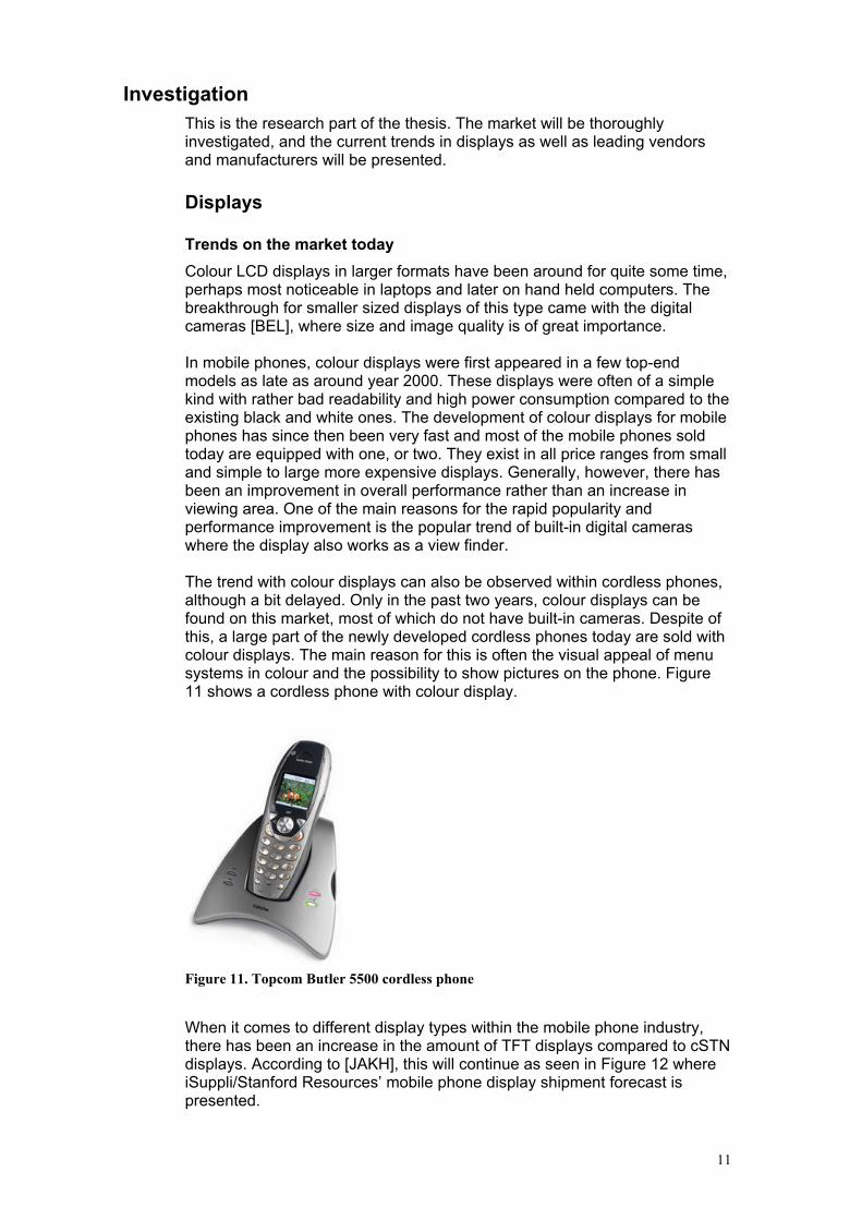
Colour LCD displays in larger formats have been around for quite some time, perhaps most noticeable in laptops and later on hand held computers. The breakthrough for smaller sized displays of this type came with the digital cameras [BEL], where size and image quality is of great importance. In mobile phones, colour displays were first appeared in a few top-end models as late as around year 2000. These displays were often of a simple kind with rather bad readability and high power consumption compared to the existing black and white ones. The development of colour displays for mobile phones has since then been very fast and most of the mobile phones sold today are equipped with one, or two. They exist in all price ranges from small and simple to large more expensive displays. Generally, however, there has been an improvement in overall performance rather than an increase in viewing area. One of the main reasons for the rapid popularity and performance improvement is the popular trend of built-in digital cameras where the display also works as a view finder. The trend with colour displays can also be observed within cordless phones, although a bit delayed. Only in the past two years, colour displays can be found on this market, most of which do not have built-in cameras. Despite of this, a large part of the newly developed cordless phones today are sold with colour displays. The main reason for this is often the visual appeal of menu systems in colour and the possibility to show pictures on the phone. Figure 11 shows a cordless phone with colour display.
Figure 11. Topcom Butler 5500 cordless phone
When it comes to different display types within the mobile phone industry, there has been an increase in the amount of TFT displays compared to cSTN displays. According to [JAKH], this will continue as seen in Figure 12 where iSuppli/Stanford Resources’ mobile phone display shipment forecast is presented.

12
It shows that both the total amount of mobile phone displays will increase at the same time as the number of cSTN displays will decrease. [JAKH] explains this development with an estimated average increase in resolution and number of colours which only TFT displays has enough capacity for. Prices are expected to fall for all types of displays. However, component suppliers want to fulfil the requirements for the higher-margin TFT markets first, and the lower-margin cSTN markets later. This will prevent a significant reduction in cSTN prices as TFT gains in popularity. An estimated price development for display panels can be found in Figure 13.
Manufacturers
There are a huge number of display manufacturers on the market. The Internet was used to find information about manufacturers and their products
Figure 12. iSuppli/Stanford Resources’ mobile phone display shipment forecast
Figure 13. iSuppli/Stanford Resources’ mobile phone display panel pricing forecast

13
to get the latest updated information [SHER]. The investigation had to be narrowed down to a limited collection of companies that best suited the target and a decision to only consider TFT displays was made. Another demand was that there should be at least some basic facts about the displays to consider that manufacturer. When comparing displays from different manufacturers, the following specifications are among the most important:
• Size: Diagonal distance of viewing area in inches
(1 inch ~ 25 mm).
• Resolution: Number of pixels (width x height).
• Colours: Numbers of different colours that can be used.
• Power consumption: Consumed current times supply voltage.
• Contrast ratio: Difference in light intensity between the brightest
white and the darkest black.
• Luminance: Measure of light intensity (in Candela per m2)
• Response time: Time for a liquid crystal cell to go from active to inactive
and back to active again.
According to the task, the displays should handle icons, photos and large amounts of text. This information must be clearly visible and the display has to fit the physical design. Thus the investigation was focused on display sizes around two inches and 65k colours and above. For resolutions, 128x128 pixels was considered a minimum. Table 1 below shows the most interesting manufacturers. A complete table of their displays is found in Appendix A.1. List of TFT display manufacturers, along with a few other manufacturers.
Table 1. The most interesting manufacturers
AU Optronics Wide range of TFT displays
FEMA Electronics Only one 1.75’’ TFT
Genesis Tech (Samsung) Interesting TFTs, partner with Samsung
Goleta Display Systems A few TFTs
Hantronix 1.8’’ and 2.0’’ TFT
Palm Technology Co. Ltd. A couple of interesting TFTs
Picvue Electronics Ltd. A few TFTs
TCI Display Co. Ltd. Several TFTs of different types
Three-Five Systems A couple of 2.2’’ TFTs
TIANMA Microelectronics Some TFTs
Toppoly Optoelectronics A lot of TFTs, specialized in LTPS
Varitronix A few TFTs, most with 262k colours
GUI development software
With more advanced graphical user interfaces, the need for efficiency gains during development is crucial. The first step might be to create a function library with commonly used actions and objects. The functions in this library can then be used and reused when developing the GUI, with considerable

14
efficiency gains. The next step is a stand-alone software where all functions are collected on a workspace in a PC application. The functions are easily accessible and there is often a visual representation in real-time of the GUI. This does not only save a lot of time, but also reduces the need of programming skills and knowledge of the underlying system.
GUI development software vendors
A number of manufacturers of GUI development software were found and investigated. All products are royalty free and include source code.
Table 2. GUI development software vendors
Manufacturer /
Product
Distinguishing
features
Prog
lang.
OS indep-
endence
Visual GUI
editor
Price
(SEK)
Segger / emWin Good
documentation
C Yes No 69 000*
Swell Software /
PEG+
Advanced objects
and graphics, large
footprint, visual
editor
C++ Yes Yes, visual
representation,
code
generation
68 000*
Swell Software /
C/PEG
Not the best but
very few
weaknesses, visual
editor
C Yes Yes, visual
representation,
code
generation
49 000*
IBIS Solutions
ApS / easyGUI
Easy to use, few
objects and simple
graphics, visual
editor
C Yes Yes, visual
representation,
object
handling, code
gen.
7 000**
Accelerated
Technology /
Nucleus GRAFIX
Advanced GUI
functions, OS
integration
C Nucleus
recomm-
ended
No ?
Express logic /
PegX
OS integration C++ ThreadX
recomm-
ended
No ?
* License per developed product ** License per user
Comparisons
All GUI development softwares (Table 2) in the study have very similar characteristics, but there are some differences that are more important to consider when deciding.
Programming language
The two programming languages of current interest are ANSI C and C++. Generally speaking, C++ has more features and can handle more complex actions. C++ is in many aspects also better suited for graphics programming. On the other hand ANSI C has a significantly lower footprint, the amount of system resources needed. An estimation is that the ANSI C footprint can be about 60% of the C++ footprint [DEL]. The only software in the study that uses C++ is PEG+ from Swell Software.
Windows
The main use of windows in the GUI is to separate different areas of the screen both sideways as well as above and under. With extensive window support there are possibilities to have pop-up windows floating above the rest

15
of the display content, to see content from two different sources at the same time by placing them side by side and to create drop-down menus. The Swell Software C/PEG has no actual window support, rather working by the principle that each screen takes up the whole display. The other softwares have at least support for resizable and movable windows with clipping, although the windows in easyGUI are highly primitive. Nucleus Grafix and PEG+ both have advanced window features like hiding, layering, data type control, vertical and horizontal scrolling, child windows and multi-line editing (still to be implemented in Nucleus at time of writing).
Fonts
To look good on a display, the fonts must be proportional and it must be possible to create new or modify existing fonts to fit the application profile. All of the software investigated had these capabilities in one way or another, as a built-in feature or a stand-alone converter.
Real-time image decoding
This feature enables conversion of images from different formats to a format that can be displayed during program execution. I.e. the user can display a photo stored in jpg format on the terminal. PEG+, PegX and emWin are the only programs that have this built in, but it will of course also require relatively large resources from the application.
Handling of menu systems
This is a very important aspect of creating a dynamical GUI. Many of he programs have similar ways of keeping track of menu objects and windows. Nucleus Grafix, PEGX, C/PEG, PEG+ and emWin give the programmer the possibility to give each item, i.e. a window or a button, their own specific id. The items can also be parents, children or siblings to other items and notification messages can automatically be sent between these. This gives a structured hierarchy of the menu system. With easyGUI it is possible to give each item their own name, but there is no further structure and it is left to the programmer to handle all events.
Differences between C/PEG and emWin
After examining the different software packages based on a theoretical investigation, it was time for a more in-depth investigation. Due to time limitations, not all softwares could be considered. C/PEG and emWin was found most suitable and was chosen for this. Some of the distinguishing features for these were that they use ANSI C and are not integrated with a certain OS.
Evaluation versions of both C/PEG and emWin were obtained from the manufacturers. By using them to create GUIs in a PC environment, the capabilities of each of the softwares could be better understood. From these experiences some differences were observed.
• A visual editor called “Window Builder” is shipped together with the C/PEG library (Figure 14). This software gives a visual representation of the GUI and can generate complete source code in ANSI C. Bundled with the Window Builder, there are several other tools to handle images, fonts, text strings and several object properties.

16
• Lists, radio buttons and checkboxes are included in both packages. When using C/PEG, radio buttons or checkboxes with functionality, can be added to a list. In emWin there is no direct functionality for combining these. However, lists can be customized to contain for example bitmaps along with text via a so called owner draw function. The programmer can then implement the desired functionality by creating bitmaps looking like checkboxes etc. //// Lists with the desired design cannot use checkboxes or radio buttons with the desired functionality in emWin. Easy to use in C/PEG.
• With emWin, Scrollbars can directly be added to lists with automatic functionality, and also be set to appear only when necessary. In C/PEG the scrollbar can only be created separately and its function is up to the programmer to implement.
• Both programs can convert bitmaps to ANSI C code that is used to display them in the GUI. C/PEG also has an object called icon which makes it simpler to display and handle bitmaps directly in real-time.
• EmWin supports real-time displaying of .bmp, .jpg and .gif files which C/PEG does not. Extra memory is recommended for decoding and displaying of the compressed formats.
• C/PEG has a “group” feature, which allows objects to logically and visually be gathered together. This makes it possible to perform common tasks on all objects in the group or to move as well as remove and add the whole group on the screen. No such feature in emWin.
• C/PEG has support for changing language in real-time on all text strings used in the GUI. Further more, a string editor is available in the Window Builder software, which allows easy string handling, including language, font ant size.
Figure 14. C/PEG WindowBuilder

17
• EmWin has a tool for displaying an executable version of the GUI in a PC environment with the possibility to show different layers or windows (Figure 15).
Figure 15. emWinView with created emWin GUI
• C/PEG has a bit more code built into the object function, which reduces the amount of coding for the programmer. Also there are a few more functions than in emWin.
• EmWin has an extensive and well-written manual, and earlier experiences say that the company behind the software is competent and reliable.
• Earlier work has been done in emWin, which means that there are already knowledge and experience in Ascom, as well as programmed code for emWin. But the programming principle in C/PEG is very similar to the one used in emWin, so large parts of the knowledge is probably fairly easy to apply in C/PEG.
State machine consideration
When creating a GUI, it is desired to make the process as dynamical as possible. This will, for example, make the menu structure of the GUI easy to change. To make the handling of states, events and actions in a menu structure easy and clear, some sort of visual representation would be helpful. For this reason, the possibility of combining a GUI program or graphical library with a state machine similar to Visual State is considered. The aim is to be able to create all graphical items as windows etc. with the GUI program and manage the different states in the state machine, with input events that triggers actions. An event can for example be a pressed key and an action can be to move from one state to another. A state machine will generate the needed code and has direct support for events as input and actions as output. Discussions with Joakim Jarfjord at Ascom, concludes that the possibility has been explored prior to this thesis work. Jarfjord attempted to combine the
18
GUI program EmWin with Visual State but found this to be complex and time consuming. The main reasons for this are stated below. A “bubble” (visual representation of a state) in Visual State does not necessarily correspond to one screen image in the menu system. For example, when scrolling through a list with arrow keys, each key event will make for a state transition. A very large number of bubbles is then needed, one for each selectable list item. If instead each screen image is defined to correspond to one state, a considerable number of properties will have to be set for each bubble, thus eliminating the desired functionality of the state machine. Furthermore, in a contact list, there should be a possibility to add items to the list which will further add to the complexity of the visual structure. The need of changing a menu system structure is practically inevitable due to changed conditions or demands. Moving a sub menu from one place in the structure to another will mean that all new transitions for that must be created and previous transitions changed or removed. There are also many different types of actions that might occur. For example, a selection in a menu could result in calling a function like connecting a call. Another selection could be to select an option with a radio button. Therefore the visual representation will be inconsistent and far from clear. One alternative to using a state machine is to define the menu structure in a header-file, which is used by the code for creating the GUI. By using the parent-child functionality and callbacks of the GUI program, each item can be related to the rest. Most of the other code can be written in general way. A lot of coding is needed for this but the main advantage is that changes to the structure easily can be made by editing the header-file. A way to improve the simplicity of creating the menu structures is to write a program in windows that enables the developer to, in a more easy-to-grasp manner, build the structure. The program should then simply generate or update the header-file.

19
Implementation
When all background information is investigated, the next natural step is to test the theory in practice. This is the part where the systems of theory is realised, constructed and tested.
Equipment
Display
One part of the thesis was to find the best suited display for the application, but the need for a display to perform tests arose before that was determined. A standard display, originally intended for digital cameras, was acquired from AU Optronics. The specifications for this display are found in [AUO].
OMAP 5912 starter kit (OSK)
This kit was the heart of the project. It consisted of a development board and a collection of board and chip specific libraries. It also contained an embedded version of Linux, but that was not used in the project. An Ascom-developed simple start-up code was sufficient. On the board there was an abundance of components and connectors. The once used in the project was; the OMAP 5912 processor, the USB connector, the RS232 connector and one expansion slot on the back side. There was also a large set of usable modules, of which these was used; LCD controller, DMA controller, a serial communications protocol called MicroWire and another protocol called UART for RS232 communication [TIHW].
OMAP 5912 processor
The processor of type OMAP 5912 is produced by Texas Instruments and is based on the ARM processor architecture. The processor has three basic clock frequencies; 12, 13 and 19 MHz and a maximum frequency of 192 MHz. The number of I/O ports is very large, since the processor has a quite special system of “balls”. One ball can hold up to 8 ports which are determined with an internal multiplexer. The ports can also be set as pull-up or pull-down, used to keep either a high or a low value respectively on the port. The processor has support for 16- or 32-bit instruction sets and an internal SRAM of 250k bytes [TIDAT].
PC
The PC was a standard machine running “Microsoft Windows XP” operating system and “Microsoft Visual C++” development environment was used during programming, but compilation was performed with “gmake”. Two channels were used to communicate with the OMAP board – one USB connection and one RS232 connection. USB was used to load the compiled code into the memory of the processor, and a small Ascom-developed program handled this loading. RS232 was only used as a feedback channel where output from the program was visible in “Microsoft HyperTerminal” which was set up to listen on the serial port COM1 on the PC.
Test board
In the beginning of the project a test board was built to hold the display, the buttons and some extra components like capacitors, resistors, inductors and transistors. A small connector was mounted that fitted the cable from the display and individual cables from a large flat cable (80 pins), that connected to the OMAP board, was welded onto the test board along with cables from

20
Figure 16. The prototype
the buttons. That structure had several advantages since all separate parts could be easily disconnected when welding or testing. It also made it possible to replace the display or to use another OMAP board. Furthermore the structure became very easy to overview and gave room for testing and fault localization.
Cables & Contacts
The OMAP board was connected with, apart from power supply, one USB cable to the PC, one RS232 cable to the PC and the flat cable to our test board. The flat cable was connected to one of the expansion slots residing on the back side of the board. The test board had several small cables, extracted from the flat cable and welded onto the board. The cable to the display was already mounted in the display module, so a special connector on the test board was all that was needed to connect the display. A photo of the complete prototype, including OMAP board, test board, display and all cables, can be seen in Figure 16.
Measuring instruments
To help with testing and evaluation during hardware construction, a Hewlett Packard 54645D mixed signal oscilloscope was used. It has two analogue inputs and sixteen digital inputs, which makes it suitable for measuring standard signals as well as parallel digital signals. The digital measurement was particularly useful when investigating the parallel signals to the LCD. For measuring of constant voltages, an ordinary multimeter of type Fluke 83 was used. There were situations where, for testing reasons, a voltage was needed to be applied over certain parts of a circuit, and a Hewlett Packard E3631A DC power supply satisfied those needs.
Prototype system
The realisation is done by constructing a prototype consisting of all the investigated elements. Both software and hardware should be tested in the prototype.
System overview

21
Figure 17. Prototype system overview.
The complete prototype system is visualized in Figure 17 above. It spans from the pure software part in the top left corner to the hardware in the bottom right. The software is a GUI, created with a GUI development tool that can handle objects of different kinds, such as windows, buttons, icons, text fields etc. These objects together make up a visual appearance of a GUI, and when adding functionality to the objects, such as click events and menu trees, the GUI is complete. All objects are visualized on the LCD by combining single pixels in different colours. How these pixels should be combined to form a button, icon or any other object is determined by the graphical functions. This is a library that contains some basic drawing operations, like dots, lines, rectangles, circles etc. Several basic operations are used together to form an object. There are also operations to draw text strings in predefined fonts. One could see a font as a translation key, from a letter code in the software to a pixel formation on the display. When the objects have been visualized with the graphical functions, they are stored in the frame buffer. The way the data is stored is tailor-made to suit the LCD controller. The frame buffer is a temporary storage area, from which the LCD controller reads when it updates the display. This reading is realised with DMA, which is a transfer method that runs outside the processor and therefore does not load the processor at all. The display used is a LCD module with power IC, integrated drivers and timing controller. Thus there is a need for an external timing generator which in this case will be the LCD controller of the OMAP. It performs a display update by sending synchronization and control signals to the LCD module along with the pixel data. There are three synchronization signals: The pixel clock is used to clock pixel data into the display and its frequency will
(DMA)
control
data
LCD module LCD
controller
GUI
tool
Graphical
functions
Output
to
frame
buffer

22
basically determine the update frequency of the display. HSYNC is a line clock that toggles each time all of the pixels in a line have been displayed and works as a horizontal synchronization signal in active mode. VSYNC is correspondingly a frame clock that toggles when all the lines in a frame have been displayed.
GUI
The graphical user interface in the prototype system consists of a set of screens, linked together in a certain structure to allow navigation between them. The main purpose of the prototype screens is to demonstrate and test the functionality of the GUI development software as well as pointing out some of the advantages when using a colour display compared to the currently used displays in Ascom’s products. Screen handling
The navigation in the GUI is performed by changing screens. A screen is a complete display area and can neither be resized nor moved. There are several ways of changing screens though, four of them are presented in Table 3. The rows denote the structure of the relation between the screens. A flat structure means that all screens are on the same level and are all siblings to one parent. To change screen in such a structure, one simply make the new screen visible instead of the old. Logically this is a simple solution but the navigation becomes quite complex, since there are no relationships between new and old screens. A hierarchical structure on the other hand, allows easy navigation because a new screen is then a child to the old screen. This means that navigating back is simply going back to the parent. Either one chooses a flat or hierarchical structure, there is a choice of creating all screens when GUI starts or create them when needed and destroy them when not. If creating at GUI start, the principal is to hide all screens but the current one. When changing screens, the old one is hidden and the new one is shown. To handle dynamic data, like posts in a phonebook, the screens must be updated with the new data when they are shown. The other approach is to start out with no screens at all, and then create them when needed. Then dynamic data is no problem but there will be some extra delay when changing screens. The memory requirement is hold down though, and to keep it down all screens not needed are destroyed and the memory is freed.
Table 3. Comparison of different methods to change screens
Create all at GUI start Create new and destroy old
Flat structure • Memory demanding
• Complex navigation
• Complex dynamic data
• Memory efficient
• Complex navigation
• Simple dynamic data
Hierarchical structure • Very memory
demanding
• Simple navigation
• Complex dynamic data
• Medium memory
requirement
• Simple navigation
• Simple dynamic data
For the prototype GUI, a hierarchical design were chosen, no screens are created when GUI is started. First when the user is navigating to a new

23
screen, that screen is created. The screen is kept in memory as long as the user is navigating below that screen in the hierarchical structure, but is destroyed as soon as the user have has navigated passed that screen when stepping back through the structure. The C/PEG software used to build the GUI, supported a maximum of 16 bits per pixel, so that mode had to be used although the display supported 24 bits per pixel. Main screen
There is a main screen in the GUI, which is created at start up time, and is in the top of the hierarchy. This screen is never destroyed and the user cannot navigate away from it, just open new screens. On the main screen, phone status, like battery power, signal strength and current user is shown. Current time and date is also shown, even though they are static in the prototype. Apart from the main screen, there are a handful other screens, from which some important are presented below.
Icon menu
The appearance of this screen is almost the same as the icon menu used in the newest of Ascom’s phones, but with colour icons and labels. The high resolution in the target display also allows borders and higher quality on the graphics overall. Because of the similar design with existing GUI, one can study the gains with using colour and high resolution.
Phonebook and contact details
The phonebook has a list of names, with one name per row, where all rows can have their own style and colour to improve readability. When user clicks a name, details of that person is shown in a new screen. The details consist of a colour picture of the person and a text field that, thanks to the high resolution, can show a large amount of information.

24
Message editing
One of the weaknesses of the C/PEG package, is the lack of multi-line editing capabilities. This is very obvious on the message editor screen, where only one row of input is supported. To support multi-line, extra work from the programmer is needed. Settings and profiles
These two screens demonstrate the built-in objects radiobuttons and checkboxes. There are simple functions to set them in on and off positions, and the package also keeps track of the state. It also makes sure that only one radiobutton is in on position at any given time.
Graphical library
All objects in the GUI development package consists of a set of primitive drawing functions, like rectangles, circles, lines and so on. There is also a set of bitmap drawing functions. All drawing functions are built-in to the package and are ready to use, but one might have to adjust some of them slightly to fit the current target system though. In the prototype no changes to the original code were needed.
Output to frame buffer
This is a function that is called when the display should be updated, either a whole screen or a smaller part of the screen. To find out what area of the display that should be updated, there is a variable called “Invalid” and is a rectangle defining the area to update. The overall algorithm in the prototype consists of the following steps; calculate the starting point in memory, loop through odd and even rows separately, extract data from the internal structure, convert the 16 bit internal data into three bytes to fit the target display and finally write the pixel data in the SRAM frame buffer.
Data transfer
Figure 18. Data transfer block scheme.
The principle of the data transfer from the processor to the LCD is described in Figure 18. The data is stored in a dedicated memory area in a special structure to suit the controller. There are eight input pins on the LCD, but the controller can not output less than sixteen bits at a time for an active TFT

25
display. Due to this, the data can only be stored on every second address, leaving every second address unused [TIDMA]. To unload the processor as much as possible, the transfer is done by direct memory access (DMA). The DMA transfer runs outside the processor, and therefore it does not load the processor at all. The transfer is just triggered to start by the processor, and then it runs by itself. The trigger occurs when the LCD controller is enabled. The DMA controller is set up with the start and stop address of the dedicated memory area, as well as the number of columns and rows of the LCD. The other important settings in the DMA controller are:
DMA LCD Channel Source Destination Parameters Register (DMA_LCD_CSDP)
Burst Enable = 1 (access 4 words at a time)
Pack Enable = 1 (pack 4 bytes in a single 32-bit-word)
DATA_TYPE = 01 (16 bits scalar word size)
DMA LCD Control Register (DMA_LCD_CTRL)
BLOCK_MODE = 0 (1 block)
BLOCK_IT_IE = 0 (no block done interrupt)
BUS_ERROR_IT_IE = 0 (no bus error interrupt)
LCD_SOURCE_PORT = 00 (memory source is SDRAM)
LCD_DEST_PORT = 0 (OMAP built-in controller)
DMA LCD Channel Control Register (DMA_LCD_CCR)
ADRMODE = Post-increment (default mode)
OMAP3_1_Compatible_disable = 1 (currently using version 3.2)
AutoInit = 1 (automatically initiate transfer when end is
reached)
Repeat = 1 (auto restart transfer when end is reached,
only if AutoInit is set)
High Prio = 1 (not needed, can increase display update speed)
Bursting and packing is not necessary but increases the transfer speed. The data type must be 16 bits though, otherwise there will be an error when receiving the data in the LCD controller. The DMA transfer should be disabled before the initialization is performed.
The first 32 bits of the memory area is the palette. It is not used by the LCD but is needed for the controller to know which format to use. The palette is transferred first to the display, and then waiting for an acknowledgement before start sending the data.
The data is sent repeatedly, since “AutoInit” and “Repeat” are set, which is necessary since an active display must be fed with new pixel data at all times. The transferred data is stored in a first-in-first-out (FIFO) buffer, allowing the LCD controller immediate access to the data it outputs to the LCD. The DMA transfer uses a dedicated physical channel to the LCD controller, so there are no conflicts on the data bus.
LCD controller
The development board contains a built-in LCD controller that connected to the display makes up the display interface. The LCD controller can be programmed to support pixel resolutions up to 1024x1024, graphics modes up to 16 bits per pixel and both STN and TFT technologies.

26
The controller consists of a number of functional blocks according to Figure 19.
Figure 19. Block scheme of the built in LCD controller.
In the upper left corner the pixel data is obtained from the DMA channel. Because the display used is of active matrix type, several of the blocks will not be used. The palette RAM is normally used to store colour values which are indexed by encoded pixel data used as pointers. In this case the palette will not be used in the normal sense but will be zero filled apart from a 3 bit value telling the controller what number of bits per pixel it should support. The dithering logic will be bypassed together with the output FIFO and the pixel data will be sent directly from the palette to the output pins without further processing [TIDISP].
The output signals that are connected to the display in our design are pin 0:7 of the pixel data, the pixel clock, HSYNC and VSYNC (see schematics in Appendix C.1. LCD interface schematics). The operation and function of the LCD controller is programmed by setting and reading from a number of registers described in [TIDISP]. In order for the controller to work properly, it is crucial that it is correctly configured for the display. The most relevant register settings for the controller along with brief explanations can be viewed below. Complete settings are found in Appendix D.1. LCD controller register settings.
LCD control register
This register contains bit-fields for basic settings like display type and turning on/off the
controller.
LCD TFT (LcdTFT) = 1 (Active display control mode)
LCD Control bit 0 (LCDCB0) = 0 (Together with LCDB1 sets the mapping
of graphics data on the output pins. 00
means 8 bits per pixel or above for either
passive monochrome and colour, or active
displays)
LCD Control bit 1 (LCDCB1) = 0 (see LCDB0)
Gated pixel clock (pxl_gated) = 0 (The pixel clock will always toggle)
Palette loading (PLM) = 01/10 (01: the frame buffer should contain only
the palette data, which is then placed in

27
the palette. 10: the frame buffer should
contain only the pixel data, which will be
send out directly to the display.
LCD Timing 0 register
This register contains four bit fields that control the HSYNC-signal generation and are set to
binary values. For more details, see Figure 20.
Pixels-Per-Line (PPL) = 1001111111 (640* pixels per, in other words, the
horizontal resolution of the display)
Horizontal Synchronization (A HSYNC pulse will be 1* VSYNC
clock long)
Pulse Width (HSW) = 000000
Horizontal Front Porch (HFP) = 10111011 (send 188* dummy pixel clocks after a
complete row of pixels has been
transmitted to the display before a new
HSYNC pulse is sent)
Horizontal Back Porch (HBP) = 00011100 (wait 29* pixel clock periods before
sending pixel data after a HSYNC pulse)
LCD Timing 1 register
This register is similar to the previous timing register except it controls the VSYNC-signal
generation and time values are defined in HSYNC periods instead of pixel clock periods. For
more details, see Figure 20.
Pixels-Per-Line (PPL) = 0011101111 (240* lines per frame, in other words, the
vertical resolution of the display)
Horizontal Synchronization (a VSYNC pulse will be 1* HSYNC
clock period)
Pulse Width (VSW) = 000000
Vertical Front Porch (VFP) = 00000000 (wait 0 HSYNC clock periods before
sending pixel data after a VSYNC pulse.
I. e. no horizontal front porch.)
Vertical Back Porch (VBP) = 00010101 (wait 21 HSYNC clock periods before
sending pixel data after a VSYNC pulse)
*Note: value is set to desired value – 1.
LCD Timing 2 register
This register contains bit fields for setting the function of the timing.
Pixel clock divider (PCD) = 00000010 (the generated clock frequency will be
divided by 2 to give a resulting clock
frequency that meets the specifications on
refresh rate of the display)
Invert VSYNC (IVS) = 1 (The polarity of VSYNC is inverted to
active low)
Invert HSYNC (IHS) = 1 (The polarity of HSYNC is inverted to
active low)
Invert Pixel Clock (IPC) = 1 (The edge of the pixel clock that drives
pixel data out onto the LCD data lines is
set to falling edge)

28
Figure 20. Timing of the OMAP LCD controller
The choice of gated pixel clock is a power saving option that is available for passive displays, which means that the clock only will toggle when there is relevant data to display. For the display used, a pixel clock is always needed during operation and is also used by the LED driver circuit (Appendix C.2. LCD application circuit schematics.). Without the clock signal the display will automatically be set in standby mode. All three of the timing registers are set to make the timing specifications end up within the limits for the display. These specifications can be found in [AUO]. While performing settings for the controller, it must be turned off in order for changes to take affect. After the controller is enabled first time, the palette data is read from the frame buffer (with PLM = 01). It will be 32 bytes (16 by 16-entry Palette’s) but only contain 3 bits of useful data and the rest will be zero-filled. Bit 14:12 in the first entry is set to 1xx, which will work for 16 bits per pixel encoding (Figure 21). After this is done, the controller is turned off, PLM is set to 10, and then it is turned on again. The rest of the data will only be pixel data.
Figure 21. First palette entry (out of 16)
One important thing to notice is that we set up the controller to send out 16 bits of pixel data at a time. However, the display supports 24 bits per pixel with an 8 bit RGB interface. This means that only one 8 bit colour element (R, G or B) will be sent at a time. Therefore, there will be 8 bits of “dummy“ data sent each time data is clocked out to the display. All timing settings are made treating each colour element as a pixel.
LCD module
Serial control of the display
The display has a serial control interface, consisting of an enable signal, a data input and a clock input. Through this interface all communication to control the display, apart from the pixel data transfer, takes place. Through

29
the OMAP board, several serial interfaces and protocols are available. Three different ways of achieving the connection were considered: The I2C module of the OMAP uses the I2C protocol that includes a clock signal line and a data signal line similar to that of the display. The connected I2C devices can be configured as a transmitter or a receiver and are recognized by unique addresses. However a two-way communication is needed because acknowledgments must be sent back from the receiver. This is not supported by the display that can only receive signals via its interface. Another method is to manually generate all three signals for the interface by setting GPIO pins. As it turned out, the transitions between a logical 0 and 1 of the GPIO outputs were to slow, resulting in the data not being correctly clocked in. MicroWire is another serial interface protocol that can be used in a similar manner as I2C. A difference is that there is no need for acknowledgements, making it suitable for the application. By using the clock signal and data out signal of the MicroWire interface together with a GPIO as the enable signal, the interface is complete (Appendix C.1. LCD interface schematics). Via the interface, 16 bit long serial commands are sent to set registers in the display module. This way initializations, as well as settings of the display, are made. A serial command is clocked bit by bit during an active enable signal [AUO]. The VSYNC signal is also needed since the serial commands are established by its pulse. This means that commands are only valid when sent during the inactive part of a VSYNC pulse and that when setting the same register more than once during a VSYNC period, only the last setting will be executed. When supplying the display with power, it will first be in standby mode, meaning the pixel elements will be turned off and nothing will be shown on the screen. It will, however, accept serial commands as well as clock signals (DCLK, HSYNC, VSYNC) and pixel data. To disable the standby mode, a certain sequence of serial commands is recommended:
• Reset register settings
• Set panel resolution
• Set scan direction (Defines the order in which the elements should be
updated. Up-to-down or down-to-up and left-to-
right or right-to-left.)
• Release standby
• Flip scan direction (Both horizontally and vertically.)
The display module has a built-in timing controller that supports different panel resolutions and therefore, the correct resolution must be set before releasing standby. Also, the flipping of scan direction is needed for initializing the bi-direction control circuit of gate and data driver.
Display related circuits
The external power supply for the display is achieved from a 3.3V pin of the OMAP and is enough to generate all needed voltages for needed for its operation. It has a built-in driver IC that provides a DC-DC charge pump, a VCOM driver and a LED boost controller.

30
The DC-DC charge pump circuit is responsible for generating the positive (VGL) and negative (VGH) power supply and needs seven external passive power setting capacitors. These are connected as shown in Appendix C.2. LCD application circuit schematics. and capacitance values are chosen according to recommended values in [AUO]. A common voltage is generated by the VCOM driver and its output pin FRP, is connected directly to the input VCOM pin. A LED booster controller in the LCD module can be used to drive a booster circuit that generates the voltage needed for the backlight. The backlight, in this case, consists of three white LEDs integrated in the module. The circuit is of the type step-up converter and is connected as shown in Appendix C.2. LCD application circuit schematics.. It is based on the application circuit found in [AUO]. A NPN switching transistor similar to the suggested is used and a regular diode is used instead of a schottky diode. Component values and descriptions can be found in Appendix C.4. DRV generates a square wave used to switch on/off the transistor T1 that works as a switch. When in closed state the left part of the circuit will be shortened and the inductor L1 will be charged by VCC. When in open state L1 will discharge through the diode D1 and provide an output current through and a voltage over the LEDs and the resistor R2. D1 and the capacitor C3 make sure the output voltage and current will remain constant also when the switch is closed [RAM]. The reason for having R2 is to give FB a feed back voltage that is used by the LED booster controller. In order to measure the obtained amplification of the circuit without risking damage to the LEDs, a resistor with an equivalent resistance is connected between the point after the diode and FB. Thus the LEDs are bypassed and the voltage drop of the resistor can be measured. For reasons presented in the “Problems” section, this circuit was, however, not used. The objective in this case was to supply power for the backlight to make the display readable. Since using a boost circuit to achieve this was not a high priority in this project, it was put aside. Instead a DC power supply generator was connected to VLED and ground with alligator clips. On this the output voltage and current could easily be set as required.
Keyboard interface
A GUI needs some kind of input and when it comes to wireless phones, mainly keypads are used. The OMAP processor contains a keyboard interface with specific I/Os supporting up to eight rows and eight columns of buttons [TIKB]. This is used to connect the keypad of a wireless phone (Appendix C.3. Keyboard interface schematics). The input pins for columns (KBC), drive a low level while the input pins for rows (KBR) are pulled up to VCC. When pushing a button, the circuit for a certain row and column will be shorted and a low level is input on one of the KBR pins. This generates an interrupt and by finding out which button is pressed, it can be used to trigger desired actions. Only the columns and rows corresponding to the buttons needed for menu navigation are connected. The interface then contains two columns and five rows resulting in ten available buttons:

31
• Three softkey buttons
• A four-way navigation button
• A mute button
• Digit buttons 2 and 5
Porting GUI library to prototype system
The pre-written GUI library was adapted to run in a windows environment. To be able to run the GUI on the OMAP development board with the target display, some adaptations had to be made.
Display functions
In the GUI development package, the primitive drawing functions are already written. They update an internal structure that holds the current appearance of the display. The parts that have to be adapted to the target are the ones handling memory management, colour palette and writing to display. Memory management deals with allocation and release of memory, which is performed differently on different systems. It is mainly used when initializing and destroying GUI objects. For the OMAP processor the standard ANSI C function to allocate and free memory is sufficient. The colour palette is used for two reasons; to tell the target display controller which mode of colour depth and number of output pins used, and to handle conversions of low quality bitmaps in the GUI to the target display. In the prototype system, these settings are already set in the boot up code. When updating the display with a new screen with its objects, a target specific function is used. This function reads from the internal structure of the display data and writes to either the display RAM directly or to a frame buffer for later transfer to the display. Because of the 8 bits per pixel serial RGB interface used in the target display of the prototype, this function has to be rather complex. Several bit operations is needed to divide the 16 bits internal data per pixel into 8 bits for each of the three colour element. Furthermore, the delta pixel configuration on the display requires different element ordering for odd and even rows, this must also be taken care of in this function. The built-in OMAP LCD controller uses DMA to read all data from a frame buffer, and then transfer the data to the display in a synchronized manner. A major drawback with that LCD controller is that there is no support for 8 pin output in TFT mode, just 12 pin or above. To use a 24 bpp display with 8 pin input, one is forced to use 16 pin output mode on the controller and write the display data on every second byte instead of every single byte. This will of course leave half the memory area filled with unused data, and the total memory requirement will double.
Keyboard driver
To be able to use all the built-in features in the GUI development package, a target-adapted keyboard driver should be written. Features like automatic logic for traversing lists and other objects as well as button presses and scrolls are all written in the package, but need to be triggered by external keyboard signals. The prototype GUI system has no target-adapted keyboard driver, rather a

32
special function that handles the key input outside the GUI package. The function figures out which key was pressed and calls suitable functions inside the package. This approach is certainly possible but is very inefficient when handling many different keys and a large variety of actions to perform.
Problems
Some difficulties and problems occurred during the development of the prototype system. The most important areas is presented and explained here.
Use of LED booster circuit
Results of the voltage measurement over the equivalent resistance, described in “Display related circuits”, showed that the obtained amplification did not reach the expected value. Several different transistors and two different inductors were tried out without success. As stated in “Display related circuits”, a DC power supply generator instead was used to supply LED power. This is not considered to be a problem in future designs as it is only a matter of choosing suitable components. There are many possible reasons why the intended amplification was not achieved:
• The 3.3 V power supply of the OMAP expansion connector is limited to 125 mA. Although an average current of appr. 69 mA is needed for the amplification, the inductor may need more than that when it is charged.
• The transistors used may not be capable of providing a big enough current for the inductor in the closed circuit (in closed state).
• A schottky diode has better performance for higher frequencies than an ordinary one. The diode used may not start to conduct fast enough when the inductor is discharged during the time of an open state since the switching frequency is rather high (appr. 370 kHz).
OMAP LCD controller and display interface
The LCD controller supports many different ways of how data is stored in the frame buffer [TIDISP]. It can be in 1, 2, 4, 8, 12 or 16 bits per pixel configurations. Still there is a rather limited amount of display panel types that are directly supported (for which the output is available on the right number of data pins):
• 1 BPP for monochrome panels, packed onto 8 (or 4) data lines.
• 3 BPP (1 bit each for red, green, and blue) for passive matrix technologies (output of dithering logic), packed onto 8 data lines.
• 12 BPP for STN (4, 4, 4) panels.
• 16 BPP for TFT (5, 6, 5) panels.
The display used is a 24 BPP TFT with an 8 bit serial RGB interface, which in this case can be considered equivalent to a 8 BPP TFT. Since there is no direct support for this, a different method must be used. Due to timing issues, the controller must be set for TFT operation which means that 16 bits will be output either way. Pixel configurations of either 8 or 16 bits per pixel in the

33
frame buffer are then the two best alternatives. 8 bits per pixel will correspond to two 8 bit pixels being output on the 16 pins at the same time while 16 bits per pixel will correspond to one 16 bit pixel at the same time. The latter alternative was chosen because it will bypass the palette and simplify the design. Thus half of the pixel data input and output to the controller will be dummy bits. Because of the 8 bit interface, there will also be three times as many transfers to the display as there are pixels.
Element arrangements
The display has a delta colour configuration and because the interface allows for one element at a time to be transferred, a way to group elements together to form pixels must be determined. Three different element arrangements, according to Figure 22, Figure 23, Figure 24, were considered.
R G B R G B R G B R G B R G B ... R G B R
G B R G B R G B R G B R G B R ... G B R G
Figure 22. Rectangles
R G B R G B R G B R G B R G B ... R G B R
G B R G B R G B R G B R G B R ... G B R G
R G B R G B R G B R G B R G B ... R G B R
G B R G B R G B R G B R G B R ... G B R G
R G B R G B R G B R G B R G B ... R G B R
G B R G B R G B R G B R G B R ... G B R G
Figure 23. Triangles (lined up)
R G B R G B R G B R G B R G B ... R G B R
G B R G B R G B R G B R G B R ... G B R G
R G B R G B R G B R G B R G B ... R G B R
G B R G B R G B R G B R G B R ... G B R G
R G B R G B R G B R G B R G B ... R G B R
G B R G B R G B R G B R G B R ... G B R G
Figure 24. Triangles (shifted)
These arrangements will have an impact on how content on the screen is perceived. In Table 4 the conceptions of a number of attributes for the different arrangements are presented.

34
Table 4. Comparison between different element arrangements
The shape of a pixel (and the resolution) will also be determined by the element arrangement. Because each colour element is twice as high as it is wide, none of the arrangements gives perfect square pixels but will have rectangular shapes according to Figure 25.
For all of the arrangements, an average of one colour element on each row will be unused. Theoretically, all 640x240 colour elements could be used to make up 51200 pixels, but instead a number of 51120 pixels is achieved in each case. The rectangles arrangement was chosen because it gave the best over all visual performance for the attributes. In order to avoid a distorted picture due to the pixel shape, compensation had to be maid both for bitmaps, text and GUI objects. This was made by simply reducing the pixel width of the picture data with 50 % on the desktop to make it appear with the right proportions on the screen.
Arrangement
Rectangles Triangles
(lined up)
Triangles
(shifted)
Colour Good Good Good
Text Good Acceptable Bad
Resolution Acceptable Bad Good
Attribute
Sharpness Good Acceptable Bad
Figure 25.
a) Rectangles 3:2 (w:h)
c) Triangles (shifted) 2:3 (w:h)
b) Triangles (lined up) 3:8 (w:h)

35
Testing and verification
Apart from ensuring that the prototype was activated correctly, a set of other tests and verifications had to be made, to confirm a correct behaviour of the more specific functions of the prototype.
Bitmap conversion
To test the LCD’s ability to display images, a software converter had to be built. The converter took an image file in BMP format and converted it into 24 bits per pixel, 8 bits per colour, suitable for the format used in the LCD.
An image in BMP format has the following structure [HET]:
In the BMP file format every row of data is inverted (Figure 26). This means that a converter software has to read the headers to find out the length of each row and then start reading from the last pixel in each row. The colour elements are positioned in the order blue, green, red and must also be inverted. The tricky part is that the number of bytes in each row must be a multiple of four and if not, the row is padded with zeros. These zeros have to be ignored by the converter software.
<>
pixels displayed on the
screen pixels stored in .bmp-file
Figure 26. BMP pixel data storage
14 bytes
40 bytes
4 * number of colours

36
Keyboard response
The prototype built had key support and to test this, a simple image switching function was implemented. The basic idea was that when a button was pressed the image displayed on the LCD was changed. There was no need for any dynamics, so a specific image was statically connected to each button. The key response should be able to occur at any point in the execution, and was therefore activated with a key interrupt, caught in the general interrupt handling routine.
LCD update
Previously used display solutions on the company, had some problems with slow update rates. This became obvious when scrolling and only the top row was updated. So the speed with which the software updated the LCD was tested as well as the correctness of the image on the LCD. This test was achieved by studying the LCD when the image changed due to above described key response test.
Speed of software
Measured execution times with OMAP processor
Raw data (fixed data to frame buffer):
Slow coding design (with if-clauses inside loops):
Full screen: 125 ms
Half width: 95 ms
Half height: 92 ms
Fast coding design (without if-clauses inside loops):
Full screen: 55 ms
Half width: 27 ms
Half height: 28 ms
GUI (internal structure to frame buffer, fast coding design):
Full screen: 93 ms
Group: 66 ms
Pop-up: 30 ms
List (2 rows): 6 ms (per list element) · 2 = 12 ms
List (4 rows + scroll): 40 ms
GUI (key press to after frame buffer update):
Full screen (depending on content): 117 ms (less text and small bitmaps)
136 ms (more text and large bitmaps)
One step in a list (content-dependent): 15 - 19 ms
Checkbox state change: 7 ms
Memory requirements
The memory required for the produced GUI is presented below:
GUI images (icons) 24 kB
GUI (incl. fonts) 74 kB
Main routine 13 kB
OSK files + start-up 15 kB
Total: 126 kB
With lib-files (cpeg, c, gcc) 240 kB
These values are only valid for this specific implementation but give a hint about the memory size of a simple colour GUI. In addition to this, during run-

37
time, an internal memory area of the current screen will be allocated. In this case it will be 213*240*16 bits.
Internal screen memory 102 kB
Electrical performance
Power consumption
To obtain values for the power consumption of the display, a number of different measurements are made, both on the display board and on the OMAP board. Since steady-state values are of most interest, a digital multimeter is used.
The OMAP board has so called test points where the current consumption of the 3.3V Vcc voltage rail which works as main power supply for most of the circuitry on the board. By measuring the voltage drop over a 0.1 Ω resistor connected in series with the power supply, the passing current, and thus power consumption can be calculated according to the following equation:
[ ],W VU VIP cc
Rcc3.3V3.3V
R==
where I3.3V is the current through the resistor R and UR is the voltage drop over it.
The power consumption for the display is determined in the same manner as above. A resistor of low impedance (1 Ω) is connected between the 3.3V output pin of the OMAP connector and input power supply pin of the display. The voltage drop is measured over this and power consumption calculated using the equation above.
Results of the measurements for the OMAP 3.3V voltage rail as well as the display can be found in Table 5.
Table 5. Measured current consumption
Conditions I3.3V_display
(mA)
I3.3V_OMAP
(mA)
LCD enabled showing GUI main screen, backlight off. 8.4 229
LCD in standby mode. 0.5 221
LCD in standby mode, LCD controller/DMA disabled. 0.0 230
Display not connected, LCD controller/DMA enabled - 220
Display not connected, LCD controller/DMA disabled - 230
Display board not connected, LCD controller/DMA enabled - 219
Display board not connected, LCD controller/DMA
disabled
- 230
The measurements show that the LCD module consumes significantly less power when in standby mode and uses a non-measurable current when the OMAP LCD controller is turned off. However, the 3.3V voltage rail of the OMAP consumes approximately 10 mA more when the LCD controller is turned off. The reason for this is unknown but it should be possible to solve.

38
What type of content is displayed when LCD is enabled also affects the power consumption. Measurements where made for three cases according to Table 6.
Table 6. Measured display current consumption for different screen contents.
Content displayed I3.3V_display (mA)
White screen 8.2
Grey screen (middle value) 8.9
Black screen 10.4
Differences in current consumption depending on what is displayed are due to the voltage supply to the transistors in the display. When a pixel is black it is in the most active mode, and a white pixel means it is in the least active mode. This can also be observed when the backlight is enabled during standby mode of the LCD where the screen is perceived as white.
Determining the power consumption of the backlight is made separate from the other measurements because of the use of a DC supply generator. A value can be calculated directly by reading the voltage and current output on the display of the generator. This gives:
mWVIP gengenbacklight 21787.10020.0 =⋅==
Note that this value is based on the recommended backlight driving conditions. Only a fraction of the power is necessary to obtain some luminance of the display. The accuracy of the generators displayed values was also verified by connecting and measuring the voltage drop over a resistor of low resistance in series with the LEDs.
Using equation x, a total power consumption of the display module for a typical case with backlight on, can be written as:
mWPPP backlightdisplayVtyptotal 7.2442177.27_3.3_ =+=+=
Digital error tolerance
When updating the display with new pixel data, there is a small time difference between the input pins when the bits changed. The flanks are not exactly aligned. The difference is never larger than approximately 10 percent of the pixel clock pulse width, so as long as data is read in the middle of each clock pulse, no errors occur.

39
Other implementations
Display considerations
Table 7 presents the data amount in bytes of one screen picture for commonly used resolutions and number of colours. It also includes the values of two presently used cordless phone displays at Ascom as well as the prototype display.
Table 7. Data amount for different resolutions and number of colours.
Number of
colours
/Resolutio
n
b/w
(1bpp)
4-level
greyscale
(2bpp)
256
(8bpp)
4 096
(12bpp)
65 536
(16bpp)
262 144
(18bpp)
16 777 216
(24bpp)
101x80 1 010 2 020 8 080 12 120 16 160 18 180 24 240
128x64 1 024 2 048 8 192 12 288 16 384 18 432 24 576
128x128 2 048 4 096 16 384 24 576 32 768 36 864 49 152
128x160 2 560 5 120 20 480 30 720 40 960 46 080 61 440
176x208 4 576 9 152 36 608 54 912 73 216 82 368 109 824
176x220 4 840 9 680 38 720 58 080 77 440 87 120 116 160
176x240 5 280 10 560 42 240 63 360 84 480 95 040 126 720
213x240 6 390 12 780 51 120 76 680 102 240 115 020 153 360
240x320 9 600 19 200 76 800 115 200 153 600 172 800 230 400
Processor considerations
If the prototype application is directly transferred to a system with less processing power, an approximation of the execution time based on number of clock cycles for a frame buffer update can be made (Table 8).
Table 8. Source code for frame buffer update: Assembler
Instruction
Numbers used
in code
Clock cycles needed per instruction (National
Instruments Processor) [CR]
Assignment x·y·8+y·4 1
Compare x·y·2+y·2 1
Memory write x·y·3 2 (memory aligned) / 3 (memory not aligned)
Addition/Subtr. x·y·9+y·7 1
Multiplication y·2 2
Bit shift x·y·3 1
Bit logic x·y·6 1
x = display resolution width; y = display resolution height
memory aligned = all 16 bit words start on even addresses in memory
Aligned: x · y (8+2+6+9+3+6) + y (4+2+7+4) = 34xy + 17y
Not aligned: x · y (8+2+9+9+3+6) + y (4+2+7+4) = 37xy + 17y
For a resolution of 213 · 240:
Aligned: 1 742 160 clock cycles
Not aligned: 1 895 520 clock cycles
Minimum execution time with a clock frequency of 20 MHz:
Ascom cordless phone display 1
Ascom cordless phone display 2
Prototype display
Values in bytes
bpp=bits per pixel

40
Aligned: 87 ms
Not aligned: 95 ms
These results are not realistic due to the assumption that the processor is used exclusively for this job but can serve as a pointer for the required processing power for different resolutions.
Memory demands
Obviously a high resolution colour display requires a lot more memory to store all pixel information. As seen in Table 7, the amount of data for a screen varies rapidly with the type of display used. The needed memory is based on the space needed by the GUI together with some memory area containing pixel data of a screen.
GUI calculation performance
Provided that a 16-bit processor and a colour depth of 16 bits or less is used, an increase in resolution and colour depth will have a negligible impact on the performance of GUI calculations. This is because a screen consists of objects that are defined by certain parameters. The size of objects is defined by coordinates which means that different sizes will claim the same space. Colours of objects are defined by bit values and different colour depths will only give small changes in the space required. The exception is the data used by bitmaps, where colour depth will be proportional to the memory space.
Display update
After GUI calculation is done, the update of the display can be divided into two steps. There is a memory writing to a frame buffer or a display RAM for the part of the screen that is to be updated. This step needs to be taken cared of outside the driver circuit and will largely be dependent of the data amount. The second step is the update of the display panel from the frame buffer (or display RAM). If a one-chip driver IC is used, this will be handled by the display module and the update speed will mainly be limited by the performance of the driver IC itself.
LCD driver circuit and interfaces
As explained in the “Basic facts” section, an driver IC for an LCD can contain a different number of built in components. If no external LCD controller is available, a driver IC with a built-in display RAM is needed. It should also contain all other parts of the driving circuit such as timing generator and timing controller.
A built-in display RAM is commonly accessible trough an MPU interface. There are often 8 or 16 pins for data (8 for 12 bpp and below and 16 for 16bpp and above) that can be used for parallel or different serial interfaces. Other signals may vary and are specific for different driver IC’s.

41
Results and conclusions
The thesis has included the graphical user interface as well as the LCD display. The important parts are on one hand the software difficulties and possibilities related to high resolution colour displays, and on the other hand the hardware. As it turns out, the software seems to be quite adaptable and will most likely not have as large impact on the early decisions in a future colour display project than the hardware. The hardware decisions are vital to keep complexity, cost and workload down.
Displays
The investigation on colour displays showed that there is a huge growth in small-sized displays thanks to the mobile phones. The recent development on this market has been that TFT displays are taking over the role as standard displays from cSTN displays. However, cSTN still has a major advantage in price. Because of this, there are very many manufacturers of TFT displays. Many of them offer a wide variety of different displays with performances similar to other manufacturers’ displays. Choosing a manufacturer is thus more a question of earlier experiences and prices. Because there are many fields of application for small colour displays, it is important to know what it should be used for. It will also place requirements on the application hardware. The largest requirements will be on the handling of large data amounts depending on resolution and colour depth. TFTs are available in the higher range of this with good overall performance while CSTN is found in the lower range. The WLAN phone has high processing power, large memory capacity and should be able to show photographic images. An example of display: TFT with a resolution of 176x220 and a colour depth of 65k colours. The DECT phones with lower processing power and small memory capacity should support colour icons and menus. An example of display: CSTN with a resolution of 128x128 and a colour depth of 256 colours. For the DECT phones, extra memory must be added. To achieve a fast enough display update, an extra processing unit or a driver IC with built in timing generation and addressable RAM will be needed, maybe even both. The power consumption will be higher than for monochrome displays, both with and without lighting. The latter especially applies for TFTs, but a common solution is to put the display in standby mode while not using it, saving most of the power consumption.
GUI development software
The investigation has shown that the number of products for GUI development is actually quite limited. The diversity between them is even smaller. Most of the products are very similar in structure and even syntax. There are a few requirements in the task that are not fulfilled in all products. One of the requirements was OS independence, which only four of the investigated softwares had, and one of these four did not fulfil the

42
requirement about event handling and advanced objects like radiobuttons. Left is two products using ANSI C:
C/PEG
emWin
and one product using C++:
PEG+ Generally PEG+ has more features than the other two, like advanced window handling and real-time image conversion. Of course this comes with a price of larger footprint, both in memory requirement and CPU load. The impression of C/PEG is that it is easy to work with, which the visual tools, like Window Builder and the string editor, contribute to. The string editor also allows real-time language switching. A major drawback is the lack of multi-line editing objects, although the vendor says that this will be included in a new version coming soon. The main advantages for emWin are the extensive documentation and that previous work has been done in the company, but the conclusion is that C/PEG is so similar that the knowledge is easily applied there too. The emWin software does support the use of image files in runtime, as well as multi-line editing. Since all three products fulfil the requirements, the choice between them will be based on the target system performance and the features of the GUI to be developed. However, none of them has support for building logical menu trees. Combining the software with a state machine was found inadequate but the menu tree can be defined in a header file with relatively good results.
Prototype implementation
The prototype system consists of all parts investigated in the thesis, from the graphical user interface to the hardware connections of the LCD display. All parts gave valuable practical experiences for the theory, and the tests will be a base for future construction of colour display systems. One of the positive experiences was how much more information that could be fitted onto the display while still retaining a good readability. This was thanks to the high resolution, but also because of the colours making the objects more distinguishable. The large colour depth made photos look good even with a lot of details, although the conclusion is that the colour depth is unnecessary high for the current application. The display used in the prototype had no built-in timing generator, but fortunately this was a built-in feature of the processor. Without this support, an extra component for timing generation would have been necessary, resulting in a lot more work. The investigations have shown however, that there are display modules with built-in timing generators, and the conclusion is that this should be a preferred choice if the processor cannot provide it. Major difficulties occurred in the prototype work, when trying to set up the serial communication with the display, to initiate the start up sequence. The communication had to be of one-way type and have the correct frequency. Another problem, at least as large, was to get the timing settings correct. There were a lot of registers to be setup, both in the LCD controller and the

43
DMA control unit. Even a very small error made the display scrambled or rolling. Finally, the fact that the display had 24 bits per pixel and a special type of colour element configuration, made the software for data transfer quite complex. The conclusion here is that 16 bits per pixel with 16 input pins on the display is recommended.

44
Discussion and future work
This project has shown that implementing colour displays in wireless phones has no single general solution. The problems that one encounter can have several solutions. The discussion will handle a few problems together with possible solutions.
Use of DMA
The total time for updating the LCD depends not only on GUI execution, memory writing and bus transfer, but also on how these different areas are connected together in the complete system solution. The ideal solution could seem to be a dedicated and addressable display RAM in the LCD controller chip. This way there would only be one memory block to be written, with the total size of one screen size, which is the current resolution times the colour depth used. This however, could cause problems when loading the CPU with other processes, probably several with higher priority than the LCD update. The CPU has to temporarily leave the display updating job, and as a result the display screen can get an incorrect appearance. Two alternative ways to avoid interrupted display updates are discussed below:
• If introducing a memory between the CPU and the display RAM, a so called frame buffer, the CPU can take its time to update this frame buffer and, when ready, trigger a DMA transfer that silently and without processor load, will transfer the data to the display RAM. The drawback will be increased times where no screen changes are visible for the user, and of course the DMA still uses the data bus. The memory requirement in this case would be twice the screen size.
• One could have a display controller with two separate display RAMs. The display panel is updated from the first while the second is loaded from DMA and not until the second RAM is completely updated, the controller changes to that RAM as update source.
If one uses DMA for the transfer to the display and a process with higher priority wants to access the data bus, the DMA must stop at once, but without giving rise to extra execution time for stopping and reinitialize the DMA and without leaving the display looking like scrambled eggs. In the national instruments processor, there is a feature called DMA freeze, which could solve the stopping problem. By simply setting a single bit in a register the DMA is automatically stopped at the current point and can be resumed as easily by setting a bit in another register.
How to make data transfer to display more efficient?
Much time and processing power is spent on writing pixel data for a screen to a memory. Say that every screen has its own memory block. For small changes in the screen, like selecting checkboxes and moving in lists, the memory for that screen is updated. When changing screens, instead of updating memory, the DMA pointers are updated to transfer from the memory block of the new screen instead.

45
The advantage of this system is a vast improvement in display update times, but of course suffers from heavy memory requirements. But since memory is easier and cheaper to add to a system, this solution may be possible. Even though the solution could be hard to implement in practice, it certainly is an interesting thought, to get the GUI data logically closer to the display.
Future work
For systems with high performance, like Ascom’s new WLAN phone, the thesis should cover most, if not all, of the areas. The conclusion that almost any colour display is possible, even though necessarily not needed, in this type of phone should be without doubt. For older systems, like the DECT phone, the answer is not that obvious. To be certain, a more thorough investigation as well as prototype testing is definitely needed. Not only in an isolated test environment as in this thesis, but with other processes running and interrupts occurring. The area of interest is mainly the display update speed – what does it take for the display to be fast enough? Regarding software, there could be of some interest to test a simple GUI, but the real use of such a work is probably quite limited. A simple bitmap transfer to the display, similar to the one used in this thesis, is most likely sufficient. The programming challenges will probably concern the initializations and settings to get the display interface up and running. Finally, the last area that has not been covered to satisfaction is market research about simpler displays of cSTN type. The manufacturers and their different alternatives in colour STN displays as well as approximate prices, is scarcely covered in the report, but will be highly interesting in a future colour display project. Meetings with TFT display manufacturers have been held in connection with the thesis and similar meetings should be held about cSTN.

46
References
[ALL] Allan R., Flat-Panel Displays: Poised To Take Over Large And Small Screens, ED Online ID #5380, 2003-07-21
[ASC] Ascom Wireless Solutions, Products, http://www.ascom.com/ws/solutions_ws/products_ws.htm, 2005-10-31
[AUO] AU Optronics, Product specifications 2.0” color LTPS TFT-LCD module, 2004
[BEL] Bellis, M., History of the Digital Camera, http://inventors.about.com/library/inventors/bldigitalcamera.htm, 2005-11-14
[CR] CompactRISC, CR16C Programmer’s Reference Manual, 2002
[DEL] DeLisle J. A. and Maxwell Kenneth G., Choosing the PEG+ or C/PEG Libraries, Swell Software, Inc., 2005
[ERC] Express Repair Center, Learn about LCD TV and TFT LCC displays, http://www.ercservice.com/learning/fabricating-tft-lcd.html, 2005-11-13
[HET] Hetzl S., The .bmp file format, http://www.fortunecity.com/skyscraper/windows/364/bmpffrmt.html, 2005-11-14
[IRA] Iranli A., Pedram M., DTM: Dynamic Tone Mapping for Backlight Scaling, University of Southern California, 2005, http://www2.dac.com/data2/42nd/42acceptedpapers.nsf/0c4c09c6ffa905c487256b7b007afb72/d077653203817ebb87256fc40070c03a/$FILE/38_1.pdf, 2005-10-31
[JAKH] Jakhanwal V., Big Growth Ahead for Small-Sized LCDs, http://www.usdc.org/resources/DisplayTrends_summer2004/biggrowthahead.htm, 2005-11-08
[MOH] Mohamed Y., LCD displays and touch screens, Ascom Tateco, 2004
[MÖL] Möller J., Bakgrundsbelysning av LCD, EmComp Scandinavia AB, 2004
[NECEL] Nec Electronics, LCD Driver ICs-keeping pace with ever-changing mobile phone, Volume 2, Scoop Eye – Innovation Channel, http://www.necel.com/en/channel/pdf/se_vol2.pdf, 2005-10-31
[NECPR] NEC Europe, NEC Enhances Lineup of TFT Colour LCDs for Mobile Telephones, Press release October 5 2001, http://www.nec.co.uk/index.aspx?id=191&pressid=197, 2005-10-31
[PDD] Pacific Display Devices, LCD Module Interface Information, http://www.pacificdisplay.com/lcd_mod_if.htm, 2005-11-11
[RAM] Ramaswamy V., Step-up swith mode power supply: Ideal boost converter, http://services.eng.uts.edu.au/~venkat/pe_html/ch07s3/ch07s3p1.htm, 2005-10-31
[SHEN] Shenzhen Pilot Technology CO, COG & TAB, http://www.pilotech.cn/Page.aspx?guid=2513&iid=2513, 2005-10-31
[SHER] Fontok, www.Sherlab.com, http://www.sherlab.com/electronics/opto_lcd.html, 2005-10-31

47
[SHFL] Sharp Microelectronics of America, Flat Panel Technologies, http://www.sharpsma.com/lcd/lcdguide/Technologies/Tech_index.php, 2005-11-11
[SHLCD] Sharp Microelectronics of America, Introduction to Liquid
Crystal Displays, http://www.sharpsma.com/lcd/lcdguide/Primer/lcd-Intro.php, 2005-11-11
[TIARCH] Texas Instruments, OMAP5912 Multimedia Processor Device Overview and Architecture Reference Guide, 2004
[TICLK] Texas Instruments, OMAP5912 Multimedia Processor Clocks Reference Guide, 2004
[TIDAT] Texas Instruments, OMAP5912 Applications Processor Data Manual, 2004
[TIDISP] Texas Instruments, OMAP5912 Multimedia Processor Display Interface Reference Guide, 2004
[TIDMA] Texas Instruments, OMAP5912 Multimedia Processor Direct Memory Access (DMA) Support Reference Guide, 2004
[TIDSP] Texas Instruments, TMS320C55x DSP CPU Programmer’s Reference Supplement, 2004
[TIGPIO] Texas Instruments, OMAP5912 Multimedia Processor General-Purpose Interface Reference Guide, 2004
[TIHW] Texas Instruments, OMAP Starter Kit (OSK) OMAP5912 Target Module Hardware Specification, Revision 2.2, 2004
[TIINI] Texas Instruments, OMAP5912 Multimedia Processor Initialization Reference Guide, 2004
[TIIRP] Texas Instruments, OMAP5912 Multimedia Processor Interupts Reference Guide, 2004
[TIKB] Texas Instruments, OMAP5912 Multimedia Processor Keyboard Interface Reference Guide, 2004
[TIPIN] Texas Instruments, OMAP5912 Multimedia Processor Pinout Reference Guide, 2004
[TISER] Texas Instruments, OMAP5912 Multimedia Processor Serial Interfaces Reference Guide, 2004
[TITIM] Texas Instruments, OMAP5912 Multimedia Processor Timers Reference Guide, 2004
[TOPTY] Toppoly, Introduction of LCD display type, http://www.toppoly.com/Toppoly/Technology/LCD_Type.asp, 2005-11-14
[TOPTF] Toppoly, What is TFT LCD?, http://www.toppoly.com/Toppoly/Technology/TFT.asp, 2005-11-14
[TOPLT] Toppoly, LTPS technology, http://www.toppoly.com/Toppoly/Technology/LTPS_Tech.asp, 2005-11-14
[USDC] United States Display Consortium, Display Technologies, http://www.usdc.org/resources/GDN_tutorials.htm, 2005-10-31
[WIKI] Wikipedia, LUX, http://www.wikipedia.org, 2005-10-31

48
Abbreviations
ACF Anisotropic Conducting Film
ANSI C American National Standard Institute C
BMP windows BitMaP
BPP Bits Per Pixel
COB Chip On Board
COF Chip On Film
COG Chip On Glass
CPU Central Processing Unit
cSTN colour Super Twist Nematic
DC Direct Current
DECT Digital Enhanced Cordless Telecommunications
DMA Direct Memory Access
GPIO General Purpose Input/Output
GUI Graphical User Interface
IC Integrated Circuit
LCD Liquid Crystal Display
LED Light Emitting Diode
MCU Memory Control Unit
MPU Micro Processor Unit
OLED Organic Light Emitting Display
OMAP Open Multimedia Access Platform
OS Operating System
OSK OMAP Starter Kit
PC Personal Computer
PEG Portable Embedded GUI
RAM Random Access Memory
SOP System On Panel
TAB Tape Automated Bounding
TFT Thin Film Transistor
USB Universal Serial Bus
WLAN Wireless Local Area Network

49
Appendix
Appendix A.1. List of TFT display manufacturers
Manufacturer
/ Model
Size Reso-
lution
Col-
ours
Cont-
rast
ratio
Lumin-
ance
Comments
AU Optronics
H019HT01 1,9” 176x220 100:1 190 cd/m2 Transflective
H018IN01 1,8” 128x160 200:1 180 cd/m2 Transmissive
H018HN01 1.8” 176x220 200:1 180 cd/m2 Transmissive
H020HN01 2,0” 176x220 200:1 150 cd/m2 Transmissive
H022QL01 2,2” 240x320 200:1 220 cd/m2 LTPS
A020BL01 2,0” 640x240 262k 200:1 240 cd/m2 LTPS
FEMA Electronics
GM280220A-18
-TTX1NCW
1,75” 280x220 100:1 140 cd/m2
Genesis Tech (Samsung)
LTS190QC-E02 1,9’’ 176x220 262k 250:1 180 cd/m2 Transflective
LTS190QC-F06 1,9’’ 176x220 65k 250:1 200 cd/m2 TMR
LTS200QV-F02 2,0’’ 240x320 262k 300:1 150 cd/m2 TMR
LTS200Q2-HF1 2,0’’ 176x220 262k /
65k
300:1 170 cd/m2 TMR
Goldentek Display Systems
GG1216N2AUW1T 1,79” 128x160 65K 200:1 180 cd/m2 Transmissive
GG1722N1AUW1T 2,0” 176x220 262K 200:1 145 cd/m2 Transmissive
GG1722N0AUW2T 2,2” 176x220 262K 200:1 145 cd/m2 Transmissive
Hantronix
HDA180 1,8” 128x160 65k 300:1 150 cd/m2 Transmissive
HDA200 2,0” 176x220 65k 150:1 150 cd/m2 Transmissive
Palm Technology Co. Ltd.
PFG18AW-TCLW 1.8’’ 128x160 Transmissive
PFG20A-TCLW 2.0’’ 176x220 Transmissive
PFG22A-TCLW 2.2’’ 176x220 Transmissive
Picvue Electronics Ltd.
SN077IKL01 1.8’’ 128x160 262k 190 cd/m2 Transmissive
SN055IKL01 2.0’’ 176x220 262k 190 cd/m2 Transmissive

50
TCI Display Co. Ltd.
1.79’’ 128x160 65k /
262k
130:1 200 cd/m2 a-Si TFT
Transmissive
1.93’’ 128x160 65k 130:1 215 cd/m2 a-Si TFT
Transmissive
1.79’’ 176x220 262k 130:1 200 cd/m2 QCIF+
Transmissive
2.0’’ 176x220 262k 130:1 205 cd/m2 QCIF+
Transmissive
2.2’’ 176x220 262k 100:1 70 cd/m2 QCIF+
Transmissive
2.2’’ 240x320 262k 150:1 100 cd/m2 LTPS TFT
Transmissive
Three-Five Systems
TFS1722-018 2.2’’ 176x220 262k 200:1 150 cd/m2 Transmissive
TFS3224-017 2.2’’ 240x320 262k 150:1 150 cd/m2 Transmissive
TIANMA Microelectronics
TM128160ANFWG 1.86’’ 128x160 262k 150:1 100 cd/m2
(min)
Transmissive
Toppoly Optoelectronics
TD018SHED2 1.8’’ 128x160 65k /
262k
80:1 110 cd/m2 Transflective
LTPS
TD022SHEB4 2.2’’ 176x220 65k /
262k
80:1 110 cd/m2 Transflective
LTPS
TD022SHEE1 2.2’’ 240x320 262k /
65k
150:1 220 cd/m2 Transflective
LTPS
TD022SREC4 2.2’’ 240x320 65k 150:1 190 cd/m2 Transflective
LTPS
TD018THEE3 1,8” 128x160 65k /
262k
300:1 220 cd/m2 TMR
LTPS
TD018THEG1 1,8” 128x160 65k /
262k
300:1 190 cd/m2 TMR
LTPS
TD019THZC1 1,9” 176x220 65k /
262k
300:1 TMR
LTPS
TD020THEE1 2,0” 176x220 262k 400:1 240 cd/m2 TMR
LTPS
TD022THEC1 2,2” 240x320 262k 300:1 250 cd/m2 TMR
LTPS
TC020THEA1 2,0” 558x234 16M 180:1 250 cd/m2 TMR
LTPS
TD020THED1 2,0” 640x240 16M 300:1 360 cd/m2 TMR
LTPS

51
Varitronix
COG-TF128160L 1.8’’ 128x160 262k 200:1 150 cd/m2 Transmissive
COG-TF176220L 2.0’’ 176x220 262k 200:1 150 cd/m2 Transmissive
COG-MOBI3007-01 2.2’’ 176x220 262k 200:1 200 cd/m2 Transmissive
COG-MOBI3015-01 2.2’’ 240x320 262k 200:1 Transmissive

52
Appendix A.2. Links to TFT display manufacturers
Ampire http://www.ampire.com.tw/
AU Optronics http://www.auo.com/
BeyondTek Inc. http://www.beyond-tek.com/
Citizen Watch Co. [Japan] http://www.citizen.co.jp/
Densitron International PLC http://www.densitron.com/
Excel-Display Corporation http://www.excel-display.com/
FEMA Electronics http://www.femacorp.com/
Giantplus Technology http://www.giantplus.com.tw/
Goldentek Display Systems http://www.goldentek.com.tw/
Hainan Qinghua LCD Technology Limited http://www.hnqhlcd.com.hk/
Hantronix http://www.hantronix.com/
Lanser Displaytech Inc. http://www.lanserd.com/
Microtips Technology http://www.microtips.com.tw/
NEC Semiconductors USA http://www.nec.com/
Ocular, Inc. http://www.ocularlcd.com/
OPTREX CORPORATION http://www.optrex.co.jp/
Palm Technology Co. Ltd. http://www.palmtech.com.tw/
Picvue Electronics Ltd. http://www.picvue.com.tw/
Purdy http://www.purdyelectronics.com/
TCI Display Co. Ltd. http://www.tcidisplay.co.kr/
Three-Five Systems http://www.threefive.com/
TIANMA Microelectronics (U.S.A) Inc. http://www.tianma.com/
Toppoly Optoelectronics Corp http://www.toppoly.com/
Truly http://www.truly.net/
United Radiant Technology http://www.urt.com.tw/
Varitronix http://www.varitronix.com/
Vbest electronics Ltd. http://www.vbest.com.tw/
Wintek http://www.wintek.com.tw/

53
Appendix B. Readability test
In order to get a general idea of the importance of display modes, a test of three handsets with different display modes is done. For the test, a lux light meter with a range of 200-50000 lux is used and the three test objects are:
Topcom Butler 5500: Wireless phone with 1.5” 4096 colour TFT display.
Sony Ericsson K500i: Mobile phone with 2.0”, 65k colour, micro reflective TFT display.
Qtek 2020i: PDA with 3.5”, 65k colour, transreflective TFT display.
Office without
fluorescent light
(200-220 lux)
Office with
fluorescent light
(580-590 lux)
Outside, daylight,
cloudy
(~11 000 lux)
Outside, daylight,
sunny
(~50 000 lux)
w.o. BL w. BL w.o. BL w. BL w. o.
BL
w. BL w. o.
BL
w. BL
Topcom
Butler
5500*
4a 6b 4a 6b 3b 4-5a 4a 4a
Sony
Ericsson
K500i
3b 7b 4b 7b 4-5b 5-6b 5a 5-6b
Qtek
2020i
2b 7b 3b 7b 4b 5-6b 4-5a 4-5a
w.o. BL = without backlight
w. BL = with backlight
1 – Not readable at all
2 – Only readable with effort
3 – “Just” readable (general variations in light and dark shades can be perceived)
4 – Somewhat readable (black text on white background ok)
5 – Average readability (also pictures are ok)
6 – Good readability
7 – Very good readability
a – Only readable in a certain angle
b – Small difference in readability from different angles
*Note: The Topcom phone never completely turns off the backlight but the brightness is reduced to a relatively low level. This is enough to read the display in dark environments without the higher level of backlight luminance.

54
Appendix C.1. LCD interface schematics

55
Appendix C.2. LCD application circuit schematics.

56
Appendix C.3. Keyboard interface schematics

57
Appendix C.4. Component list
Component id Description Value
C1 Power setting capacitor 4.7 µF
C2 “ 1 µF
C3 “ 1 µF
C4 “ 1 µF
C5 “ 1 µF
C6 “ 1 µF
C7 “ 4.7 µF
C8 Capacitor 10 µF
C9 Capacitor 1 nF
C10 Capacitor 10 µF
L1 Inductor 33 µH
R1 Resistor 10 kΩ
R2 Resistor 30 Ω
T1 NPN switching transistor -
D1 Diode -

58
Appendix D.1. LCD controller register settings
LCD Control Register (LcdControl)
Descr. Reserved 565
ST
N
TF
T
M
AP
LC
D
C
B1
PLM FDD
Bit 31 30 29 28 27 26 25 24 23 22 21 20 19 18 17 16
Reset X X X X X X X 0 0 0 0 0 0 0 0 0
Value 0 0 0 0 0 0 0 0 0 0 0/1 1/0 0 0 0 0
Descr. FDD PX
L
_G
A
TE
D
LIN
E
_INT
_CL
R_S
EL
M8
B
LC
D
C
B0
Lc
d
TF
T
lin
e
_in
t
_m
a
sk
Lin
e
_int
_ni
rq_
ma
sk
Loa
d
Mas
k
Do
ne
M
as
k
VS
Y
N
C_
ma
sk
L
c
d
B
W
Lc
dE
n
Bit 15 14 13 12 11 10 9 8 7 6 5 4 3 2 1 0
Reset 0 0 0 0 0 0 0 0 0 0 0 0 0 0 0 0
Value 0 0 0 0 0 0 0 0 1 0 0 0 0 0 0 0/1
LCD Timing 0 Register (LcdTiming0)
Descr. HBP HFP
Bit 31 30 29 28 27 26 25 24 23 22 21 20 19 18 17 16
Reset 0 0 0 0 0 0 0 0 0 0 0 0 0 0 0 0
Value 0 0 0 1 1 1 0 0 1 0 1 1 1 0 1 1
Descr. HSW PPL
Bit 15 14 13 12 11 10 9 8 7 6 5 4 3 2 1 0
Reset 0 0 0 0 0 0 0 0 0 0 0 0 1 1 1 1
Value 0 0 0 0 0 0 1 0 0 1 1 1 1 1 1 1
LCD Timing 1 Register (LcdTiming1)
Descr. VBP VFP
Bit 31 30 29 28 27 26 25 24 23 22 21 20 19 18 17 16
Reset 0 0 0 0 0 0 0 0 0 0 0 0 0 0 0 0
Value 0 0 0 1 0 1 0 1 0 0 0 0 0 0 0 0
Descr. VSW LPP
Bit 15 14 13 12 11 10 9 8 7 6 5 4 3 2 1 0
Reset 0 0 0 0 0 0 0 0 0 0 0 0 0 0 0 0
Value 0 0 0 0 0 0 0 0 1 1 1 0 1 1 1 1
LCD Timing 2 Register (LcdTiming2)
Descr. Reserved ON_
OFF
RF IEO IPC IHS IVS ACBI
Bit 31 30 29 28 27 26 25 24 23 22 21 20 19 18 17 16
Reset 0 0 0 0 0 0 0 0 0 0 0 0 0 0 0 0
Value 0 0 0 0 0 0 1 0 0 1 1 1 0 0 0 0
Descr ACB PCD
Bit 15 14 13 12 11 10 9 8 7 6 5 4 3 2 1 0
Reset 0 0 0 0 0 0 0 0 0 0 0 0 0 0 0 0
Value 0 0 0 0 0 0 0 0 0 0 0 0 0 0 1 0

59
Appendix D.2. DMA register settings
DMA LCD Channel Source Destination Parameters Register (DMA_LCD_CSDP)
Descr. BURST_
EN_B2
PA
CK
_
EN
_B
2
DATA_ TYPE_ B2
RESE RVED
BURST_ EN_B1
PACK_ EN_B1
RESE RVED
DATA_ TYPE_ B1
Bit 15 14 13 12 11 10 9 8 7 6 5 4 3 2 1 0
Reset 0 0 0 0 0 ND ND 0 0 0 ND ND ND ND 0 0
Value 0 0 0 0 0 0 0 1 0 1 0 0 0 0 0 1
DMA LCD Control Register (DMA_LCD_CTRL)
Descr. RESERVED
L D P
LSP
BUS_ ERR OR_ IT_ COND
BLO CK_ 2_IT_
COND
BLO CK_ 1_IT_
COND
BUS_ ERR OR_ IT_IE
BLO CK_ IT_IE
BLO CK_ MODE
Bit 15 14 13 12 11 10 9 8 7 6 5 4 3 2 1 0
Reset 0 0 0 0 0 0 0 0 0 0 ND ND ND ND ND ND
Value 0 0 0 0 0 0 0 0 0 0 0 0 0 0 0 0
DMA LCD Channel Control Register (DMA_LCD_CCR)
Descr. SRC_ AMODE
_ B2
SRC_ AMODE_
B1
end_ prog
OMAP
3_1_ disable
REP EAT
AUTO INIT
ENA BLE
PRIO
RESE RVED
BS
RESERVED
Bit 15 14 13 12 11 10 9 8 7 6 5 4 3 2 1 0
Reset 0 0 0 0 0 0 0 0 0 0 0 0 0 0 0 0
Value 0 0 0 1 0 1 1 1 1 1 0 0 0 0 0 0


![Content Sharing Between Spatially-Aware Mobile Phones and ... · Content Sharing Between Spatially-Aware Mobile Phones and Large Vertical Displays switches [33]. Furthermore, they](https://img.pdfslide.us/doc/110x75/6002b1484da74f553f51223a/content-sharing-between-spatially-aware-mobile-phones-and-content-sharing-between.jpg)
![LNCS 8119 - PointerPhone: Using Mobile Phones for Direct ...As mobile phones are ubiquitously available, they enable users to access remote displays in diverse ways [2]. For instance,](https://img.pdfslide.us/doc/110x75/5fbedaa67b46b93bc0137a40/lncs-8119-pointerphone-using-mobile-phones-for-direct-as-mobile-phones-are.jpg)