1
Digital Color Camera Series COLOR VIDEO CAMERA Color CCD COLOR VIDEO CAMERA Color CCD Digital P/N : 3810-0018H (Ver.0511) PRINTED IN KOREA Color Video Camera Series Design and specifications are subject to change without notice. OWNER'S MANUAL DIGITAL CAMERA SERIES COLOR VIDEO CAMERA 4 2 5 6 7 8 9 10 11 12 13 3 14 15 16 17 19 18 21 20 23 22 1. SAFETY INSTRUCTIONS 2. PRECAUTIONS 3. FEATURES 4. NAME AND FUNCTIONS 5 6 7 8 9 10 11 5. INSTALLATION (LENS) 6. COMPOSITION 7. CONNECTIONS 8. SPECIFICATIONS ............. ............................ .................................. ............. ...................... ............ ................ 12 13 14 15 16 17 18 18 20 ................ .......................... .................. ........................... .......................... ........................... ....................... ..................... ........... FL (Flickerless) If the camera is used with 50Hz fluorescent lighting, there maybe flicker on the screen. In this case, FL switch should be set to ON position. But, FL switch should be set to OFF in 60Hz power source. Flickerless mode can overcome flickering on the screen in case that the AC power frequency is different from the vertical sync frequency of the camera. AGC (Automatic Gain Control) With AGC ON, the setting, camera's sensitivity is automatically increased when the level of ambient light drops. AGC function automatically controlls signal gain in the range of maximum 28dB. BLC (Back Light Compensation) Strong light entering from an object's background may cause the lens iris to close, there by possibly obscuring or darkening desired portions of the scene. Back Light Compensation function automatically adjust the video level so as to preserve visibillity in important section of the scene. Read Instructions Read all of the safety and operating instructions before using the product. High Sensitivity 1/3 Inch Super HAD CCD Pick-up. Min lllumination : 0.1 Lux Normal Resolution 0.3 / 0.5 Lux High Resolution Auto/Manual Iris lens Selectable. AGC (Automatic Gain Control) BLC (Back Light Compensation) on/off Flickerless ON/OFF High Resolution : Horizontal 550 / 480 TV Lines High Resolution 380 TV Lines Normal Resolution Installation Do not place this product on an unstable cart, stand, or table. The product may fall causing serious injury to a child or adult, and damage to the product. Use only with a cart or stand recommended by the manufacturer, or sold with the product. Mounting should follow the manufacturer's instructions, and should use a mounting accessory recommended by manufacturer. Power source This product should be operated only from the type of power source indicated on the marking label. If you are not sure of the type of power supplied to your home, consult your dealer or local power company. Retain Instructions Save this instructions for later use. Cleaning Unplug this appliance from wall outlet before cleaning. Do not use liquid cleaners or aerosol cleaners. Use a damp cloth for cleaning. Water and Moisture. Do not use this product near water or moisture. (For example. near a bathtub, wash bowl, kitchen sink, or laundry tub, in a wet basement, or near a swimming pool,etc) Handling Tripod Mounting base Mounting base for installing the camera. C-Mount Lens Adapter Used to attach C-mount lens. (See page 13) Lens Mount Cap Be sure to cap the lens mount when the lens is not mounted. ON ON OFF ON FL OFF AGC ON BLC OFF OFF ON FL OFF ON FL OFF AGC ON BLC OFF OFF ON AGC ON BLC OFF Side-view Rear-view CAUTION! TO REDUCE THE RISK OF ELECTRIC SHOCK, DO NOT REMOVE COVER (OR BACK). NO USER-SERVICEABLE PARTS INSIDE. REFER SERVICING TO QUALIFIED SERVICE PERSONNEL. CAUTION RISK OF ELECTRIC SHOCK DO NOT OPEN Explanation of two Symbols The lightning flash with arrowhead symbol, within an equilateral triangle, is intended to alert the user to the presence of un-insulated "dangerous voltage" within the product's enclosure that may be of sufficient magnitude to constitute a risk of electric shock to persons. The exclamation point within an equilateral triangle is intended to alert the user to the presence of important operating and maintenance- (servicing) instructions in the literature accompanying the appliance. THE GRAPHIC SYMBOLS WITH SUPPLEMENTAL MARKING ARE ON THE BOTTOM OF THE SYSTEM. "WARNING-TO PREVENT FIRE OR SHOCK HAZARD, DO NOT EXPOSE THE UNIT TO RAIN OR MOISTURE" INFORMATION This equipment has been tested and found to comply with limits for a Class A digital device, pursuant to part 15 of the FCC Rules. These limits are designed to provide reasonable protection against harmful interference when the equipment is operated in a commercial environment. This equipment generates, uses, and can radiate radio frequency energy and, if not installed and used in accordance with the instruction manual, may cause harmful interference to radio communications. Operation of this equipment in a residential area is likely to cause harmful interference in which case the user will be required to correct the interference at their own expense. WARNING The manufacturer could void the user's authority to operate the equipment. CAUTION - To prevent electric shock and risk of fire hazards: Do NOT use power sources except for that specified. Do NOT expose this appliance to rain or moisture. This installation should be made by a qualified service person and should abide to all local codes. Before using this camera, please read this operation manual carefully to obtain the best result and keep this manual for future reference. Thank you for purchasing this COLOR VIDEO CAMERA. . Mode Setting Dip Switch . Lens Connector . Back-focus Adjustment . Mounting a Lens . AC 24V / DC 12V Input Model . DC 12V Input Model . AC 24V / DC 12V Input Model . DC 12V Input Model Do not disassemble the camera and never touch parts inside the camera. Be sure the ambient temperature is less than 40in installation intended for long term continuous operation. Avoid installing in a humid or dusty place. Avoid installing in places where there are strong magnetic fields and electric signals. Avoid installing in places where the camera would be subject to strong vibrations. Never expose the camera to rain and water. Installation and storage Do not point the camera at the sun. This could damage the camera whether it is operating or not. Do not install the camera where the temperature could exceed the allowable range. Do not drop the camera or subject it to shocks and vibrations to avoid possible damage. When attaching or removing the lens, handle with care in order to that moisture and dust do not enter the camera. DC 12V DC VIDEO ELC AGC ON OFF ON ON FL OFF BLC OFF VIDEO OUT Class 2 Only DC LEVEL 1 2 3 4 IRIS DC Level Control Volume (See page 12) Lens Connector (See page 17) Video Output Connector (BNC-Type) Lens Select Switch Mode Setting Dip Switch (See page 11) Power Input Terminal Rear-view DC VIDEO ELC AGC ON OFF ON ON FL OFF BLC OFF AC 24V / DC 12V VIDEO OUT Class 2 Only LINE LOCK DC LEVEL 1 2 3 4 IRIS DC Level Control Volume (See page 12) Lens Connector (See page 17) Video Output Connector (BNC-Type) Lens Select Switch Mode Setting Dip Switch (See page 11) Power Input Terminal Back-Focus Screw (See page 14) CS-Mount Lens Adapter Mount for installing the lens. Signal system CCD Pick-up Element Effective Pixels Video Output Sync. System Luminance S/N Ratio Horizontal Resolution Sensitivity Lens Mount Electronic Shutter NTSC PAL NTSC PAL 2:1 Interlace Transfer 1/3 Inch Super HAD CCD 768(H) x 494(V) 752(H) x 582(V) 510(H) x 492(V) 500(H) x 582(V) Composite: 1.0V p-p, 75Ω, Unbalanced Internal Sync More than 48dB (AGC OFF) 550 / 480 TV Lines 380 TV Lines 0.3 / 0.5Lux(F1.4, 30IRE, AGC ON) 0.1Lux(F1.4, 30IRE, AGC ON) C/CS Mount 1/60 ~1/100,000 (NTSC), 1/50 ~1/100,000(PAL) Normal Resolution High Resolution White Balance Auto Gain Control Back Light Compensation Flickerless Applicable Lens Supply Voltage Power Consumption Operating Temperature Storage Temperature External Dimensions Weight AWB On/Off Selectable(20dB) On/Off Selectable(28dB) On/Off Selectable On/Off Selectable DC Iris / Video Iris / Manual Lens DC 12V(10V~15V) 180mA / 2.2W (Max) 140mA 1.7W (Max) -10~+50(Recommendation:-5~+40) -20~+60[Long Body] 63.6x 54x 129.7mm [Middle Body] 63.6x 54x 94.1mm [Long Body] 390g [Middle Body] 335g Signal system CCD Pick-up Element Effective Pixels Video Output Sync. System Luminance S/N Ratio Horizontal Resolution Sensitivity Lens Mount Electronic Shutter NTSC PAL NTSC PAL 2:1 Interlace Transfer 1/3 Inch Super HAD CCD 768(H) x 494(V) 752(H) x 582(V) 510(H) x 492(V) 500(H) x 582(V) Composite: 1.0V p-p, 75Ω, Unbalanced Internal Sync More than 48dB (AGC OFF) 550 / 480 TV Lines 380 TV Lines 0.3 / 0.5Lux(F1.4, 30IRE, AGC ON) 0.1Lux(F1.4, 30IRE, AGC ON) C/CS Mount 1/60 ~1/100,000 (NTSC), 1/50 ~1/100,000(PAL) Normal Resolution High Resolution MODEL MODEL White Balance Auto Gain Control Back Light Compensation Flickerless Applicable Lens Supply Voltage Power Consumption Operating Temperature Storage Temperature External Dimensions Weight AWB On/Off Selectable(20dB) On/Off Selectable(28dB) On/Off Selectable On/Off Selectable DC Iris / Video Iris / Manual Lens AC 24V(20V~28V) or DC 12V(10V~15V) 330mA / 4W (Max) 240mA 2.8W (Max) -10~+50(Recommendation:-5~+40) -20~+60[Long Body] 63.6x 54x 129.7mm [Middle Body] 63.6x 54x 94.1mm [Long Body] 390g [Middle Body] 335g . User Information . Contents 2. PRECAUTIONS 4. NAME AND FUNCTIONS 1. SAFETY INSTRUCTIONS Please insert a lens cable when using the DC iris lens or Video iris lens. Lens select switch on the rear pannel should be set to ELC position when using the manual lens. When using the VIDEO type lens, please adjust a brightness of image with volume attached with the lens. When using the DC type lens, please adjust a brightness of image by DC level volume on the rear panel. - Turn toward L (left) to make the picture brighter. - Turn toward R (right) to make the picture darker. DC 12V DC VIDEO ELC AGC ON OFF ON ON FL OFF BLC OFF VIDEO OUT Class 2 Only DC LEVEL 1 2 3 4 IRIS 5. INSTALLATION (LENS) Video Type lens : Set lens Switch to Video. Connect the lens cable of a video Type lens. If the plug on the cable is a different type, replace it with the provided 4-pin iris plug. DC type lens : Set lens switch to DC. Connect the lens cable of a DC(Galvanometric) type lens. If the plug on the cable is a different type, replace it with the provided 4-pin iris plug. Pin Assignment : #1 #3 #2 #4 Pin No. #1 #2 #3 #4 Signal +12V DC N.C Video(0.7Vp-p, high impedance, no sync) GND VIDEO Iris Type Lens Pin No. #1 #2 #3 #4 Signal Damping coil (-) Damping coil (+) Drive coil (+) Drive coil (-) DC Iris Type Lens When using an auto-iris lens, install the accessory lens plug on the lens cable as follows. NOTE After installing the connector plug, connect it to the lens connector on the rear panel of camera. 1 1 1 1 1 ............................ ...................................................... ...................................................... ...................................................... ...................................................... . Lens Connector Plug (E-4-191J-100) . Lens Mount Cap . C-mount Adapter . L-Wrench . Owner's Manual ! Design and specifications are subject to change without notice. This color video camera is designed to output video signals conforming to the NTSC(PAL) standard. So that it cannot be used with video recorder or color monitors which use color systems other than NTSC(PAL) The lens mount cap and C-mount adapter are attached when supplied. 6. COMPOSITION DC 12V DC VIDEO ELC AGC ON OFF ON ON FL OFF BLC OFF VIDEO OUT Class 2 Only DC LEVEL 1 2 3 4 IRIS Connect the video output of the camera to the video input of a monitor or other equipment. When using a "loop through" connection of two or more monitors, set the 75Ω switch of only the final monitor to on. Determine the type of cable according to the distance of the connected equipment. DC 12V Power Source NOTE Do not turn any component's power on until all connections are completed. To Power input terminal To Video input connector To Lens connector Video-Iris Lens (or galvanometric-Iris Lens) 7 . CONNECTIONS 8. SPECIFICATIONS 3. FEATURES DC 12V Input Model DC 12V Input Model 8. SPECIFICATIONS AC 24V / DC 12V Input Model . Memo Mode Setting Dip Switch AC 24V / DC 12V Input Model WITH A ZOOM LENS 1) Fully open the aperture and set the lens to the maximum tele-photo position. Then turn the focus ring to focus. In the case of an auto-iris lens only, shoot a comparatively dark object so that the aperture is fully open. 2) Set the lens to its maximum wide-angle position. 3) Loosen the two back-focus screws with a L-wrench, and turn the lens mount to focus. 4) After adjusting the back-focus, tighten the back-focus screw. 5) Repeat step 1)~3) until the difference between focusing position 1) and 2)becomes smallest. CAUTION : Do not forcibly turn back-focus screw, it could cause damage to the camera. When a lens is mounted, adjustment of the back-focus may sometimes be required. Adjust the lens focus ring when the correct focus cannot be obtained. WITH A FIXED-FOCUS LENS 1) Fully open the aperture and set the focus ring to ""(infinity). In the case of an auto-iris lens only, shoot a comparatively dark object so that the aperture is fully open. 2) Loosen the two back-focus screws with a L-wrench, and turn the lens mount to focus. 3) After adjusting the back-focus, tighten the back-focus screw. Back-focus Adjustment 1 Remove the lens mount cap from the camera. 2 Attach or remove the C-mount adapter depending on the lens to be used. 3 Attach the lens to the lens mount. Secure it so that it does not become loose. 5 When installing a fixed lens, lens select switch should be set to ELC position. 4 If the lens has an auto-iris mechanism, connect the lens cable to the lens connector. -When installing a video-iris lens, lens switch should be set to VIDEO position. -When installing a galvanometric-iris lens, lens switch should be set to DC position. 1) Set AGC mode to off. 2) When using a video type lens: Adjust the level control on the lens to produce minimum smear and optimum pictures. 3) When using a DC type lens: Adjust the video level control on the main menu to produce minimum smear and optimum pictures. 4) Set AGC mode to on. It is recommended that the AGC be used in the "on" mode after adjusting the video level. -If the adapter is attached so tightly that it is difficult to remove it. (Keep the C-mount adapter for possible future use.) ADJUSTING AUTO-IRIS LENSES L-Wrench Mounting a Lens Lens Connector

COLOR VIDEO CAMERA Digital Color (Camera … Color (Camera Series COLOR VIDEO CAMERA ... Design and specifications are 2subject to change without notice. ... NAME AND FUNCTIONS 1

Embed Size (px)

Citation preview

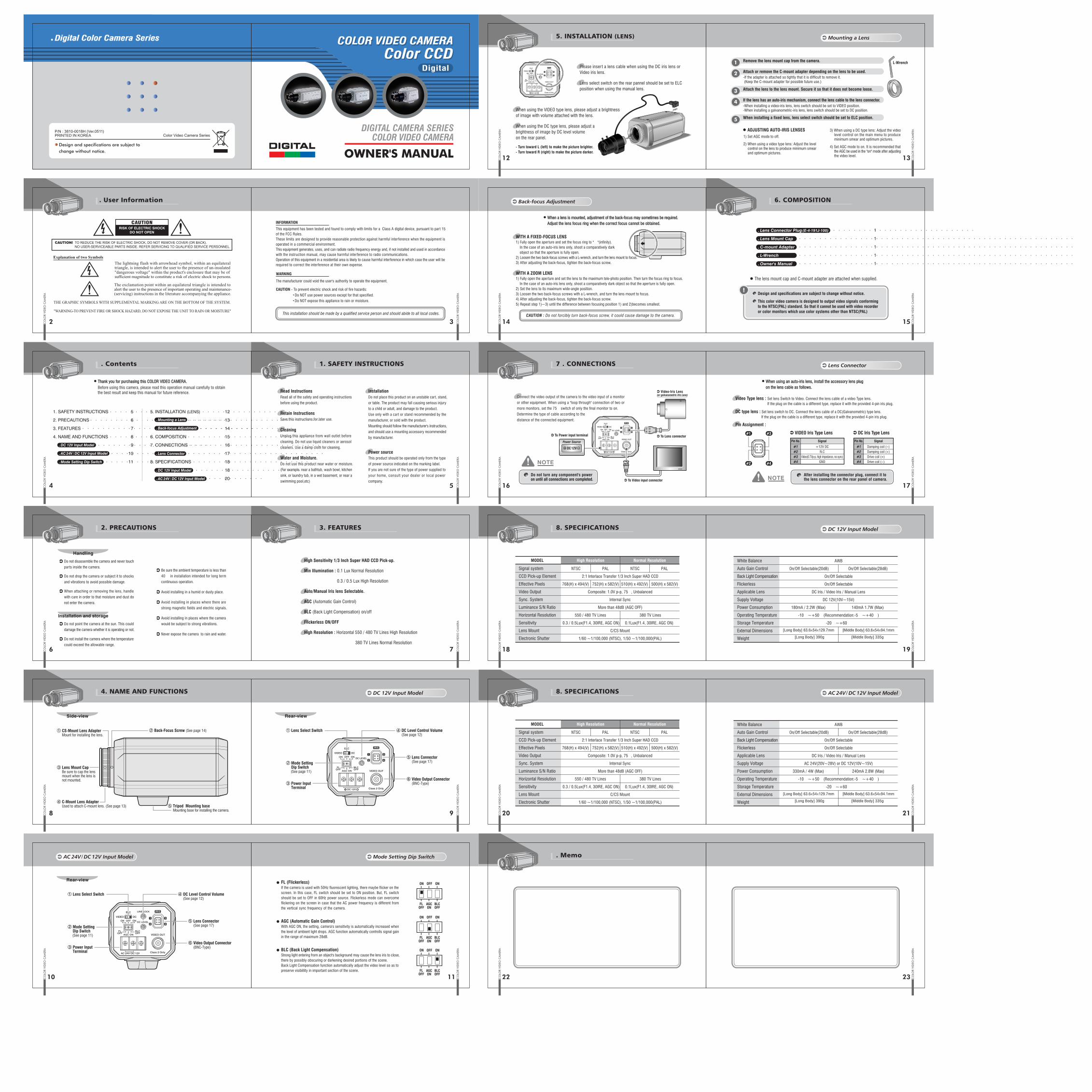
Digital Color Camera Series COLOR VIDEO CAMERAColor CCD

COLOR VIDEO CAMERAColor CCD

Digital

P/N : 3810-0018H (Ver.0511)PRINTED IN KOREA Color Video Camera Series

Design and specifications are subject to change without notice. OWNER'S MANUAL

DIGITAL CAMERA SERIESCOLOR VIDEO CAMERA

4

2

5

6 7

8 9

10 11

12 13

3 14 15

16 17

1918

2120

2322

1. SAFETY INSTRUCTIONS

2. PRECAUTIONS

3. FEATURES

4. NAME AND FUNCTIONS

5

6

7

8

9

10

11

5. INSTALLATION (LENS)

6. COMPOSITION

7. CONNECTIONS

8. SPECIFICATIONS

.........................................

...............................................

..................................

................

12

13

14

15

16

17

18

18

20

..........................................

..............................................................................................................................................

...........

FL (Flickerless)If the camera is used with 50Hz fluorescent lighting, there maybe flicker on the screen. In this case, FL switch should be set to ON position. But, FL switch should be set to OFF in 60Hz power source. Flickerless mode can overcome flickering on the screen in case that the AC power frequency is different from the vertical sync frequency of the camera.

AGC (Automatic Gain Control)With AGC ON, the setting, camera's sensitivity is automatically increased when the level of ambient light drops. AGC function automatically controlls signal gain in the range of maximum 28dB.

BLC (Back Light Compensation)Strong light entering from an object's background may cause the lens iris to close, there by possibly obscuring or darkening desired portions of the scene.Back Light Compensation function automatically adjust the video level so as to preserve visibillity in important section of the scene.

Read InstructionsRead all of the safety and operating instructions

before using the product.

High Sensitivity 1/3 Inch Super HAD CCD Pick-up.

Min lllumination : 0.1 Lux Normal Resolution

0.3 / 0.5 Lux High Resolution

Auto/Manual Iris lens Selectable.

AGC (Automatic Gain Control)

BLC (Back Light Compensation) on/off

Flickerless ON/OFF

High Resolution : Horizontal 550 / 480 TV Lines High Resolution

380 TV Lines Normal Resolution

InstallationDo not place this product on an unstable cart, stand,

or table. The product may fall causing serious injury

to a child or adult, and damage to the product.

Use only with a car t or stand recommended by the

manufacturer, or sold with the product.

Mounting should follow the manufacturer's instructions,

and should use a mounting accessory recommended

by manufacturer.

Power sourceThis product should be operated only from the type

of power source indicated on the marking label.

If you are not sure of the type of power supplied to

your home, consult your dealer or local power

company.

Retain InstructionsSave this instructions for later use.

CleaningUnplug this appliance from wall outlet before

cleaning. Do not use liquid cleaners or aerosol

cleaners. Use a damp cloth for cleaning.

Water and Moisture.Do not use this product near water or moisture.

(For example. near a bathtub, wash bowl, kitchen

sink, or laundry tub, in a wet basement, or near a

swimming pool,etc)

Handling

⑤ Tripod Mounting base Mounting base for installing the camera.

④ C-Mount Lens Adapter Used to attach C-mount lens. (See page 13)

③ Lens Mount Cap Be sure to cap the lens mount when the lens is not mounted.

ON

ON

OFF ON

FLOFF

AGCON

BLCOFF

OFF ON

FLOFF

ON

FLOFF

AGCON

BLCOFF

OFF ON

AGCON

BLCOFF

Side-view Rear-view

CAUTION! TO REDUCE THE RISK OF ELECTRIC SHOCK, DO NOT REMOVE COVER (OR BACK).NO USER-SERVICEABLE PARTS INSIDE. REFER SERVICING TO QUALIFIED SERVICE PERSONNEL.

CAUTIONRISK OF ELECTRIC SHOCK

DO NOT OPEN

Explanation of two Symbols

The lightning flash with arrowhead symbol, within an equilateraltriangle, is intended to alert the user to the presence of un-insulated "dangerous voltage" within the product's enclosure that may be of sufficient magnitude to constitute a risk of electric shock to persons.

The exclamation point within an equilateral triangle is intended toalert the user to the presence of important operating and maintenance-(servicing) instructions in the literature accompanying the appliance.

THE GRAPHIC SYMBOLS WITH SUPPLEMENTAL MARKING ARE ON THE BOTTOM OF THE SYSTEM.

"WARNING-TO PREVENT FIRE OR SHOCK HAZARD, DO NOT EXPOSE THE UNIT TO RAIN OR MOISTURE"

INFORMATION

This equipment has been tested and found to comply with limits for a Class A digital device, pursuant to part 15 of the FCC Rules. These limits are designed to provide reasonable protection against harmful interference when the equipment is operated in a commercial environment.This equipment generates, uses, and can radiate radio frequency energy and, if not installed and used in accordance with the instruction manual, may cause harmful interference to radio communications.Operation of this equipment in a residential area is likely to cause harmful interference in which case the user will be required to correct the interference at their own expense.

WARNING

The manufacturer could void the user's authority to operate the equipment.

CAUTION - To prevent electric shock and risk of fire hazards: Do NOT use power sources except for that specified. Do NOT expose this appliance to rain or moisture.

This installation should be made by a qualified service person and should abide to all local codes.

Before using this camera, please read this operation manual carefully to obtain the best result and keep this manual for future reference.

Thank you for purchasing this COLOR VIDEO CAMERA.

. Mode Setting Dip Switch

. Lens Connector

. Back-focus Adjustment

. Mounting a Lens

. AC 24V / DC 12V Input Model

. DC 12V Input Model

. AC 24V / DC 12V Input Model

. DC 12V Input Model

Do not disassemble the camera and never touch

parts inside the camera.Be sure the ambient temperature is less than

40℃ in installation intended for long term

continuous operation.

Avoid installing in a humid or dusty place.

Avoid installing in places where there are

strong magnetic fields and electric signals.

Avoid installing in places where the camera

would be subject to strong vibrations.

Never expose the camera to rain and water.

Installation and storage

Do not point the camera at the sun. This could

damage the camera whether it is operating or not.

Do not install the camera where the temperature

could exceed the allowable range.

Do not drop the camera or subject it to shocks

and vibrations to avoid possible damage.

When attaching or removing the lens, handle

with care in order to that moisture and dust do

not enter the camera.

DC 12V

DCVIDEO

ELC

AGC ON

OFF ONON

FLOFF

BLCOFF

VIDEO OUT

Class 2 Only

DC LEVEL

1

2

3

4

IRIS

④ DC Level Control Volume (See page 12)

⑤ Lens Connector (See page 17)

⑥ Video Output Connector (BNC-Type)

① Lens Select Switch

② Mode Setting Dip Switch (See page 11)

③ Power Input Terminal

Rear-view

DCVIDEO

ELC

AGC ON

OFF ONON

FLOFF

BLCOFF

AC 24V / DC 12V

VIDEO OUT

Class 2 Only

LINE LOCK

DC LEVEL

1

2

3

4

IRIS

④ DC Level Control Volume (See page 12)

⑤ Lens Connector (See page 17)

⑥ Video Output Connector (BNC-Type)

① Lens Select Switch

② Mode Setting Dip Switch (See page 11)

③ Power Input Terminal

② Back-Focus Screw (See page 14)① CS-Mount Lens Adapter Mount for installing the lens.

Signal system

CCD Pick-up Element

Effective Pixels

Video Output

Sync. System

Luminance S/N Ratio

Horizontal Resolution

Sensitivity

Lens Mount

Electronic Shutter

NTSC PAL NTSC PAL

2:1 Interlace Transfer 1/3 Inch Super HAD CCD

768(H) x 494(V) 752(H) x 582(V) 510(H) x 492(V) 500(H) x 582(V)

Composite: 1.0V p-p, 75Ω, Unbalanced

Internal Sync

More than 48dB (AGC OFF)

550 / 480 TV Lines 380 TV Lines

0.3 / 0.5Lux(F1.4, 30IRE, AGC ON) 0.1Lux(F1.4, 30IRE, AGC ON)

C/CS Mount

1/60 ~1/100,000 (NTSC), 1/50 ~1/100,000(PAL)

Normal ResolutionHigh Resolution White Balance

Auto Gain Control

Back Light Compensation

Flickerless

Applicable Lens

Supply Voltage

Power Consumption

Operating Temperature

Storage Temperature

External Dimensions

Weight

AWB

On/Off Selectable(20dB) On/Off Selectable(28dB)

On/Off Selectable

On/Off Selectable

DC Iris / Video Iris / Manual Lens

DC 12V(10V~15V)

180mA / 2.2W (Max) 140mA 1.7W (Max)

-10℃~+50℃(Recommendation:-5℃~+40℃)

-20℃~+60℃

[Long Body] 63.6x54x129.7mm [Middle Body] 63.6x54x94.1mm

[Long Body] 390g [Middle Body] 335g

Signal system

CCD Pick-up Element

Effective Pixels

Video Output

Sync. System

Luminance S/N Ratio

Horizontal Resolution

Sensitivity

Lens Mount

Electronic Shutter

NTSC PAL NTSC PAL

2:1 Interlace Transfer 1/3 Inch Super HAD CCD

768(H) x 494(V) 752(H) x 582(V) 510(H) x 492(V) 500(H) x 582(V)

Composite: 1.0V p-p, 75Ω, Unbalanced

Internal Sync

More than 48dB (AGC OFF)

550 / 480 TV Lines 380 TV Lines

0.3 / 0.5Lux(F1.4, 30IRE, AGC ON) 0.1Lux(F1.4, 30IRE, AGC ON)

C/CS Mount

1/60 ~1/100,000 (NTSC), 1/50 ~1/100,000(PAL)

Normal ResolutionHigh ResolutionMODEL

MODEL

White Balance

Auto Gain Control

Back Light Compensation

Flickerless

Applicable Lens

Supply Voltage

Power Consumption

Operating Temperature

Storage Temperature

External Dimensions

Weight

AWB

On/Off Selectable(20dB) On/Off Selectable(28dB)

On/Off Selectable

On/Off Selectable

DC Iris / Video Iris / Manual Lens

AC 24V(20V~28V) or DC 12V(10V~15V)

330mA / 4W (Max) 240mA 2.8W (Max)

-10℃~+50℃(Recommendation:-5℃~+40℃)

-20℃~+60℃

[Long Body] 63.6x54x129.7mm [Middle Body] 63.6x54x94.1mm

[Long Body] 390g [Middle Body] 335g

. User Information

. Contents

2. PRECAUTIONS

4. NAME AND FUNCTIONS

1. SAFETY INSTRUCTIONS

Please inser t a lens cable when using the DC iris lens or Video iris lens.

Lens select switch on the rear pannel should be set to ELCposition when using the manual lens.

When using the VIDEO type lens, please adjust a brightness of image with volume attached with the lens.

When using the DC type lens, please adjust a brightness of image by DC level volume on the rear panel.

- Turn toward L (left) to make the picture brighter.- Turn toward R (right) to make the picture darker.

DC 12V

DCVIDEO

ELC

AGC ON

OFF ONON

FLOFF

BLCOFF

VIDEO OUT

Class 2 Only

DC LEVEL

1

2

3

4

IRIS

5. INSTALLATION (LENS)

Video Type lens : Set lens Switch to Video. Connect the lens cable of a video Type lens. If the plug on the cable is a different type, replace it with the provided 4-pin iris plug.

DC type lens : Set lens switch to DC. Connect the lens cable of a DC(Galvanometric) type lens. If the plug on the cable is a different type, replace it with the provided 4-pin iris plug.

Pin Assignment :

#1 #3

#2 #4

Pin No.

#1#2#3#4

Signal

+12V DCN.C

Video(0.7Vp-p, high impedance, no sync)GND

VIDEO Iris Type Lens

Pin No.

#1#2#3#4

Signal

Damping coil (-)Damping coil (+)Drive coil (+)Drive coil (-)

DC Iris Type Lens

When using an auto-iris lens, install the accessory lens plug on the lens cable as follows.

NOTE After installing the connector plug, connect it to the lens connector on the rear panel of camera.

1

1

1

1

1

....................................................................................................................................................................................................................................................

. Lens Connector Plug (E-4-191J-100)

. Lens Mount Cap

. C-mount Adapter

. L-Wrench

. Owner's Manual

!Design and specifications are subject to change without notice.

This color video camera is designed to output video signals conforming to the NTSC(PAL) standard. So that it cannot be used with video recorder or color monitors which use color systems other than NTSC(PAL)

The lens mount cap and C-mount adapter are attached when supplied.

6. COMPOSITION

DC 12V

DCVIDEO

ELC

AGC ON

OFF ONON

FLOFF

BLCOFF

VIDEO OUT

Class 2 Only

DC LEVEL

1

2

3

4

IRIS

Connect the video output of the camera to the video input of a monitor

or other equipment. When using a "loop through" connection of two or

more monitors, set the 75Ω switch of only the final monitor to on.

Determine the type of cable according to the

distance of the connected equipment.

DC 12V

Power Source

NOTE

Do not turn any component's power on until all connections are completed.

To Power input terminal

To Video input connector

To Lens connector

Video-Iris Lens (or galvanometric-Iris Lens)

7 . CONNECTIONS

8. SPECIFICATIONS3. FEATURES

DC 12V Input Model

DC 12V Input Model

8. SPECIFICATIONS AC 24V / DC 12V Input Model

. MemoMode Setting Dip SwitchAC 24V / DC 12V Input Model

WITH A ZOOM LENS1) Fully open the aperture and set the lens to the maximum tele-photo position. Then turn the focus ring to focus. In the case of an auto-iris lens only, shoot a comparatively dark object so that the aperture is fully open.2) Set the lens to its maximum wide-angle position.3) Loosen the two back-focus screws with a L-wrench, and turn the lens mount to focus.4) After adjusting the back-focus, tighten the back-focus screw.5) Repeat step 1)~3) until the difference between focusing position 1) and 2)becomes smallest.

CAUTION : Do not forcibly turn back-focus screw, it could cause damage to the camera.

When a lens is mounted, adjustment of the back-focus may sometimes be required. Adjust the lens focus ring when the correct focus cannot be obtained.

WITH A FIXED-FOCUS LENS1) Fully open the aperture and set the focus ring to "∞"(infinity). In the case of an auto-iris lens only, shoot a comparatively dark object so that the aperture is fully open.2) Loosen the two back-focus screws with a L-wrench, and turn the lens mount to focus.3) After adjusting the back-focus, tighten the back-focus screw.

Back-focus Adjustment

1 Remove the lens mount cap from the camera.

2 Attach or remove the C-mount adapter depending on the lens to be used.

3 Attach the lens to the lens mount. Secure it so that it does not become loose.

5 When installing a fixed lens, lens select switch should be set to ELC position.

4 If the lens has an auto-iris mechanism, connect the lens cable to the lens connector.-When installing a video-iris lens, lens switch should be set to VIDEO position.-When installing a galvanometric-iris lens, lens switch should be set to DC position.

1) Set AGC mode to off.

2) When using a video type lens: Adjust the level control on the lens to produce minimum smear and optimum pictures.

3) When using a DC type lens: Adjust the video level control on the main menu to produce minimum smear and optimum pictures.

4) Set AGC mode to on. It is recommended that the AGC be used in the "on" mode after adjusting the video level.

-If the adapter is attached so tightly that it is difficult to remove it. (Keep the C-mount adapter for possible future use.)

ADJUSTING AUTO-IRIS LENSES

L-Wrench

Mounting a Lens

Lens Connector