Embed Size (px)
Citation preview
Color Matching for Metallic Coatings
Jayant Silva and Kristin J. Dana
Rutgers University
Abstract. Metallic coatings change in appearance as the viewing andillumination direction change. Matching of such finishes requires a matchof color as viewed under di!erent lighting and viewing conditions, as wellas texture, i.e. matching the spatial distribution of color. The systemdescribed in this paper provides a purely objective and automatic matchmeasure for evaluating the goodness of a color match. A new texturecamera has been utilized in this work to capture multiview images ofthe coating to be analyzed under di!erent illumination angles. Thesemultiview images are used to characterize the color travel of a coatingas well as analyze the appearance attributes of the finish such as orangepeel, sparkle, and texture of the flakes within the coating.
1 Introduction
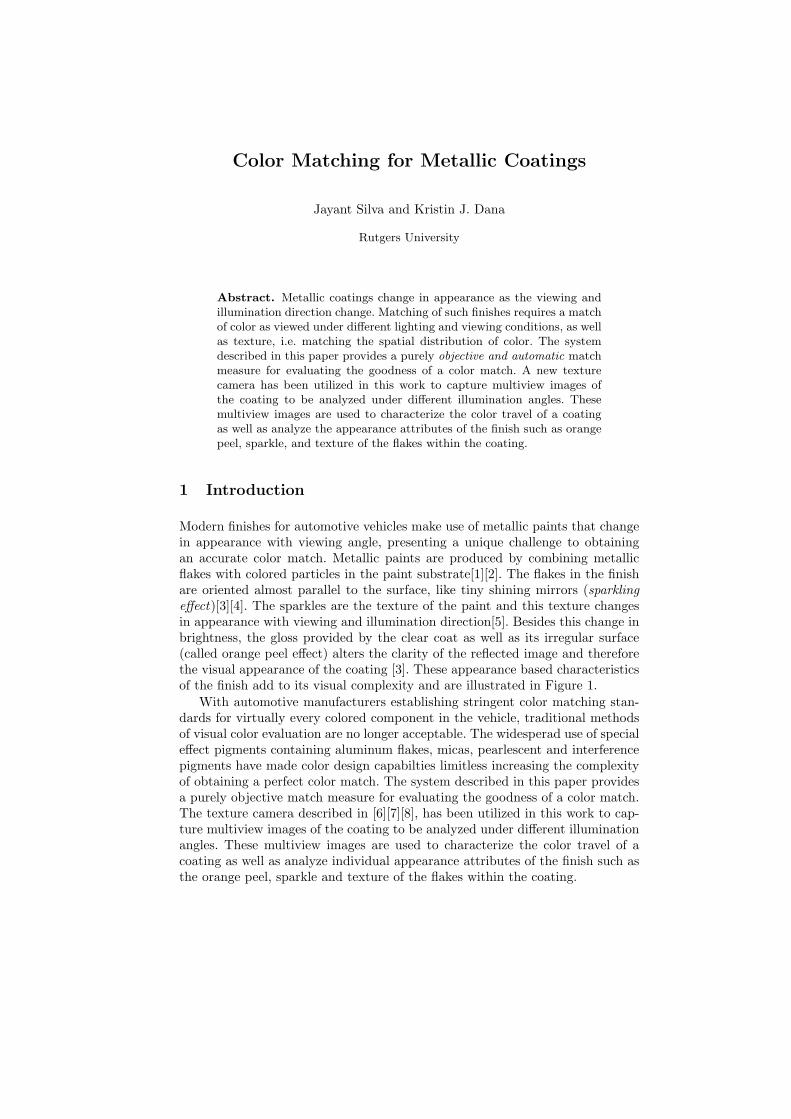
Modern finishes for automotive vehicles make use of metallic paints that changein appearance with viewing angle, presenting a unique challenge to obtainingan accurate color match. Metallic paints are produced by combining metallicflakes with colored particles in the paint substrate[1][2]. The flakes in the finishare oriented almost parallel to the surface, like tiny shining mirrors (sparklinge!ect)[3][4]. The sparkles are the texture of the paint and this texture changesin appearance with viewing and illumination direction[5]. Besides this change inbrightness, the gloss provided by the clear coat as well as its irregular surface(called orange peel e!ect) alters the clarity of the reflected image and thereforethe visual appearance of the coating [3]. These appearance based characteristicsof the finish add to its visual complexity and are illustrated in Figure 1.
With automotive manufacturers establishing stringent color matching stan-dards for virtually every colored component in the vehicle, traditional methodsof visual color evaluation are no longer acceptable. The widesperad use of speciale!ect pigments containing aluminum flakes, micas, pearlescent and interferencepigments have made color design capabilties limitless increasing the complexityof obtaining a perfect color match. The system described in this paper providesa purely objective match measure for evaluating the goodness of a color match.The texture camera described in [6][7][8], has been utilized in this work to cap-ture multiview images of the coating to be analyzed under di!erent illuminationangles. These multiview images are used to characterize the color travel of acoating as well as analyze individual appearance attributes of the finish such asthe orange peel, sparkle and texture of the flakes within the coating.
2 Jayant Silva and Kristin J. Dana
Fig. 1. Left: Color travel of an automotive coating. The presence of metallic flakescauses the blue paint to show a change in brightness with viewing angle. The coatingappears brightest at near specular angles. The brightness then decreases as the as-pecular angle increases. This change is brightness is termed as color travel [9]. Noticehow the color travel enhances the visual appearance of the curved surface. The sparkleand texture of the flakes is also seen clearly. An orange peel e!ect can also be seen byobserving the reflected image in the coating. Right: Three black paint samples showingvarying degrees of orange peel e!ect. Shown in the figure is a reflection of a fluorescentlight fixture seen in the panels. Notice that while the reflected image appears hazy insample A, it is clear in samples B and C. The orange peel e!ect is clearly seen whenone observes the roughness of the grid like pattern of the fixture reflected in Panel C.
2 Matching Technique
The variation in brightness with viewing and illumination angle exhibited bythe a metallic flake finish is captured by the BRDF ( bidirectional reflectancedistribution function). Since the BRDF of each finish is unique, it can be usedas a match measure to di!erentiate between coatings that closely resemble eachother. Measurement of the BRDF using traditional methods such as a goniore-flectometer is cumbersome [10]. In these traditional devices, the sensor and lightsource are moved to multiple combinations of viewing and illumination angles.Instead, we make use of a texture camera [6][7][8], that can measure multipleviews of a surface using a simple imaging procedure. The device instantaneouslyrecords reflectance from multiple viewing directions over a partial hemisphereand conveniently controls the illumination direction over the hemisphere. Thereare no angular movements of parts, only planar translations of an aperture anda mirror.
2.1 Measurement Device
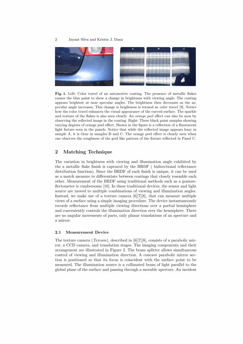
The texture camera (Texcam), described in [6][7][8], consists of a parabolic mir-ror, a CCD camera, and translation stages. The imaging components and theirarrangement are illustrated in Figure 2. The beam splitter allows simultaneouscontrol of viewing and illumination direction. A concave parabolic mirror sec-tion is positioned so that its focus is coincident with the surface point to bemeasured. The illumination source is a collimated beam of light parallel to theglobal plane of the surface and passing through a movable aperture. An incident
Color Matching for Metallic Coatings 3
ray reflecting o! the mirror will reach the surface at an angle determined bythe point of intersection with the mirror. Therefore, this aperture can be usedfor convenient orientation of the illumination direction. The aperture ensuresthat only a spot of the concave mirror is illuminated, and therefore one illumi-nation direction is measured for each aperture position. The light reflected ateach angle is reflected from the mirror to a parallel direction and diverted bythe beam splitter to the camera. The camera is equipped with an orthographicor telecentric lens that images the light parallel to the optical axis. The camerathat is positioned so that its optical axis lies along the X-axis views the imageof the mirror. The image of the mirror as now seen by the camera correspondsto reflectance measurements from all angles in a partial hemisphere as seen inFigure 3.The images captured by a CCD camera can be used to extract specificviewing angles.
X
Y
Z
Fig. 2. BRDF/BTF Measurement Device. The surface point is imaged by a CCD videocamera observing an o!-axis concave parabolic mirror to achieve simultaneous obser-vation of a large range of viewing directions. The device achieves illumination directionvariations using simple translations of the illumination aperture. Measurements of bidi-rectional texture are accomplished by translating the surface in the X - Y plane. Thelab prototype (right) can be miniaturized for a compact device. The diagram on theleft shows the light source along the Z axis, while the prototype shows the light sourcepositioned along the Y axis. Both configurations are valid.
2.2 Imaging Procedure
The spatial sampling of the imaged surface is obtained through planar trans-lations of the sample surface. The spatial sampling, or equivalently the size ofthe texture image pixel, is therefore controlled by the movement of the surface.The stage can be made to move in very small increments (0.0025 mm for thecurrent prototype), although the optical imaging principles limit the system res-olution. To obtain a texture image, the illumination aperture is positioned toachieve the correct illumination direction. A single pixel that corresponds to thedesired viewing direction is identified in the camera image. The surface is thentranslated along a two dimensional grid in the X-Y plane. The pixel is acquired
4 Jayant Silva and Kristin J. Dana
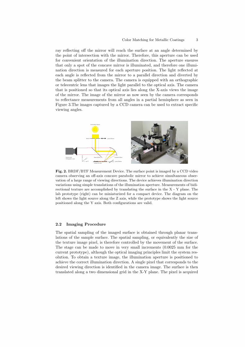
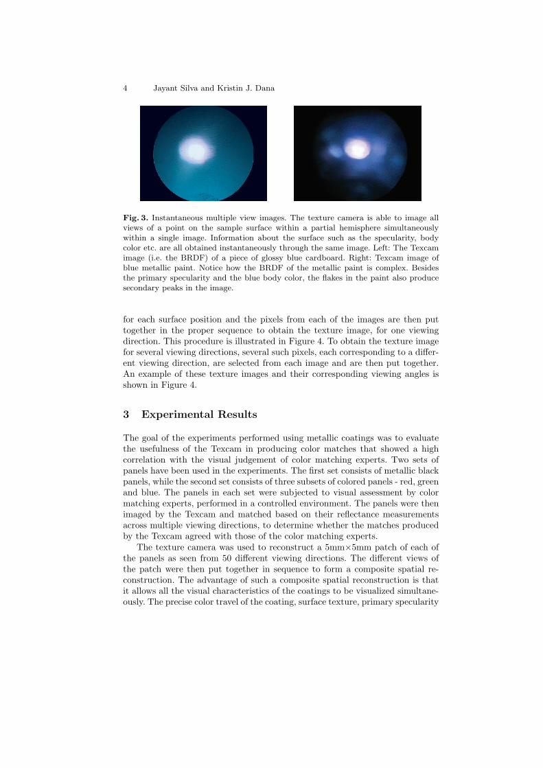
Fig. 3. Instantaneous multiple view images. The texture camera is able to image allviews of a point on the sample surface within a partial hemisphere simultaneouslywithin a single image. Information about the surface such as the specularity, bodycolor etc. are all obtained instantaneously through the same image. Left: The Texcamimage (i.e. the BRDF) of a piece of glossy blue cardboard. Right: Texcam image ofblue metallic paint. Notice how the BRDF of the metallic paint is complex. Besidesthe primary specularity and the blue body color, the flakes in the paint also producesecondary peaks in the image.
for each surface position and the pixels from each of the images are then puttogether in the proper sequence to obtain the texture image, for one viewingdirection. This procedure is illustrated in Figure 4. To obtain the texture imagefor several viewing directions, several such pixels, each corresponding to a di!er-ent viewing direction, are selected from each image and are then put together.An example of these texture images and their corresponding viewing angles isshown in Figure 4.
3 Experimental Results
The goal of the experiments performed using metallic coatings was to evaluatethe usefulness of the Texcam in producing color matches that showed a highcorrelation with the visual judgement of color matching experts. Two sets ofpanels have been used in the experiments. The first set consists of metallic blackpanels, while the second set consists of three subsets of colored panels - red, greenand blue. The panels in each set were subjected to visual assessment by colormatching experts, performed in a controlled environment. The panels were thenimaged by the Texcam and matched based on their reflectance measurementsacross multiple viewing directions, to determine whether the matches producedby the Texcam agreed with those of the color matching experts.
The texture camera was used to reconstruct a 5mm!5mm patch of each ofthe panels as seen from 50 di!erent viewing directions. The di!erent views ofthe patch were then put together in sequence to form a composite spatial re-construction. The advantage of such a composite spatial reconstruction is thatit allows all the visual characteristics of the coatings to be visualized simultane-ously. The precise color travel of the coating, surface texture, primary specularity
Color Matching for Metallic Coatings 5
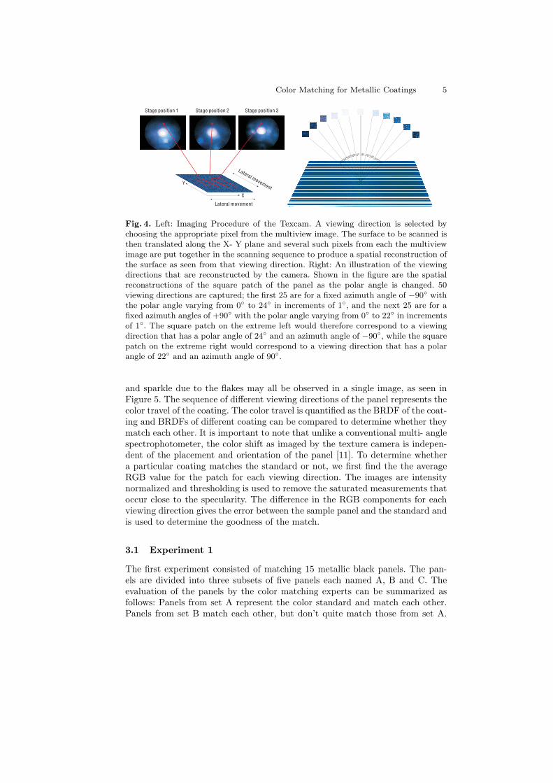
Fig. 4. Left: Imaging Procedure of the Texcam. A viewing direction is selected bychoosing the appropriate pixel from the multiview image. The surface to be scanned isthen translated along the X- Y plane and several such pixels from each the multiviewimage are put together in the scanning sequence to produce a spatial reconstruction ofthe surface as seen from that viewing direction. Right: An illustration of the viewingdirections that are reconstructed by the camera. Shown in the figure are the spatialreconstructions of the square patch of the panel as the polar angle is changed. 50viewing directions are captured; the first 25 are for a fixed azimuth angle of !90! withthe polar angle varying from 0! to 24! in increments of 1!, and the next 25 are for afixed azimuth angles of +90! with the polar angle varying from 0! to 22! in incrementsof 1!. The square patch on the extreme left would therefore correspond to a viewingdirection that has a polar angle of 24! and an azimuth angle of !90!, while the squarepatch on the extreme right would correspond to a viewing direction that has a polarangle of 22! and an azimuth angle of 90!.
and sparkle due to the flakes may all be observed in a single image, as seen inFigure 5. The sequence of di!erent viewing directions of the panel represents thecolor travel of the coating. The color travel is quantified as the BRDF of the coat-ing and BRDFs of di!erent coating can be compared to determine whether theymatch each other. It is important to note that unlike a conventional multi- anglespectrophotometer, the color shift as imaged by the texture camera is indepen-dent of the placement and orientation of the panel [11]. To determine whethera particular coating matches the standard or not, we first find the the averageRGB value for the patch for each viewing direction. The images are intensitynormalized and thresholding is used to remove the saturated measurements thatoccur close to the specularity. The di!erence in the RGB components for eachviewing direction gives the error between the sample panel and the standard andis used to determine the goodness of the match.
3.1 Experiment 1
The first experiment consisted of matching 15 metallic black panels. The pan-els are divided into three subsets of five panels each named A, B and C. Theevaluation of the panels by the color matching experts can be summarized asfollows: Panels from set A represent the color standard and match each other.Panels from set B match each other, but don’t quite match those from set A.
6 Jayant Silva and Kristin J. Dana
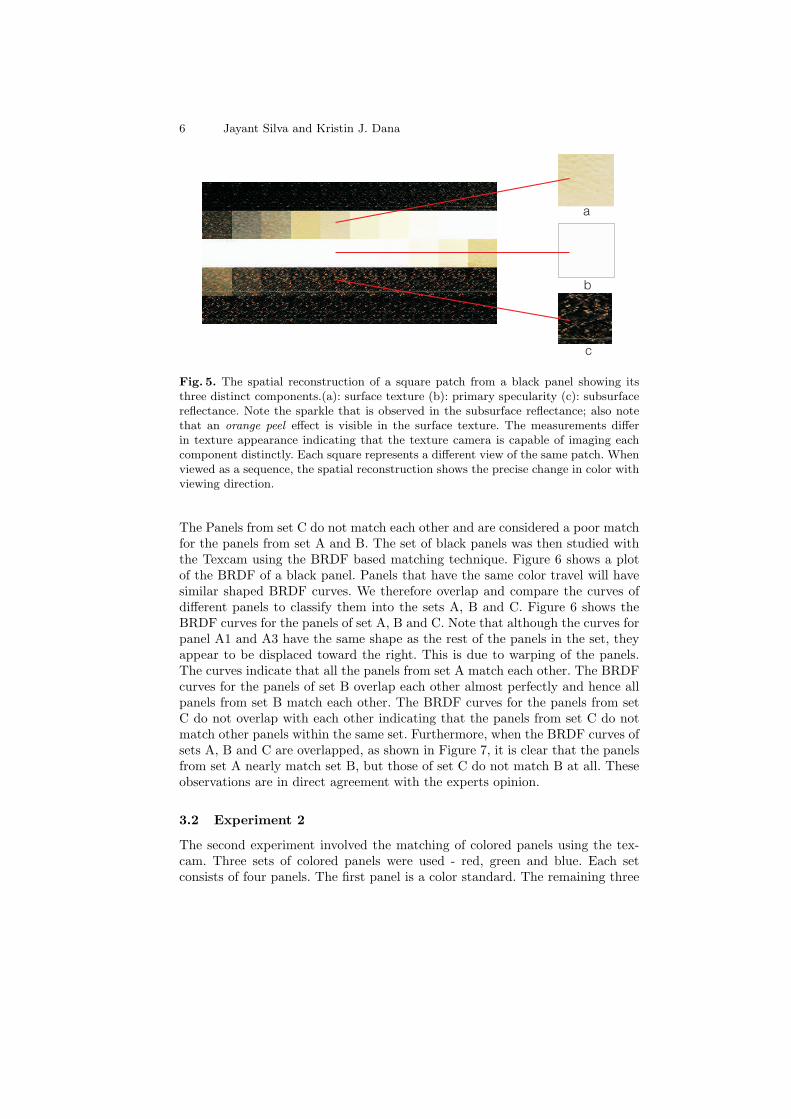
Fig. 5. The spatial reconstruction of a square patch from a black panel showing itsthree distinct components.(a): surface texture (b): primary specularity (c): subsurfacereflectance. Note the sparkle that is observed in the subsurface reflectance; also notethat an orange peel e!ect is visible in the surface texture. The measurements di!erin texture appearance indicating that the texture camera is capable of imaging eachcomponent distinctly. Each square represents a di!erent view of the same patch. Whenviewed as a sequence, the spatial reconstruction shows the precise change in color withviewing direction.
The Panels from set C do not match each other and are considered a poor matchfor the panels from set A and B. The set of black panels was then studied withthe Texcam using the BRDF based matching technique. Figure 6 shows a plotof the BRDF of a black panel. Panels that have the same color travel will havesimilar shaped BRDF curves. We therefore overlap and compare the curves ofdi!erent panels to classify them into the sets A, B and C. Figure 6 shows theBRDF curves for the panels of set A, B and C. Note that although the curves forpanel A1 and A3 have the same shape as the rest of the panels in the set, theyappear to be displaced toward the right. This is due to warping of the panels.The curves indicate that all the panels from set A match each other. The BRDFcurves for the panels of set B overlap each other almost perfectly and hence allpanels from set B match each other. The BRDF curves for the panels from setC do not overlap with each other indicating that the panels from set C do notmatch other panels within the same set. Furthermore, when the BRDF curves ofsets A, B and C are overlapped, as shown in Figure 7, it is clear that the panelsfrom set A nearly match set B, but those of set C do not match B at all. Theseobservations are in direct agreement with the experts opinion.
3.2 Experiment 2
The second experiment involved the matching of colored panels using the tex-cam. Three sets of colored panels were used - red, green and blue. Each setconsists of four panels. The first panel is a color standard. The remaining three
Color Matching for Metallic Coatings 7
0 5 10 15 20 25 30 35 40 45 500
50
100
150
200
250
300
Viewing Direction 0!50
Inte
nsi
ty 0
!2
55
A1,A3
A2, A4, A5
0 5 10 15 20 25 30 35 40 45 500
50
100
150
200
250
300
Viewing Direction 0!50
Inte
nsi
ty 0
!2
55
0 5 10 15 20 25 30 35 40 45 500
50
100
150
200
250
300
Viewing Direction 0!50
Inte
nsi
ty 0
!2
55
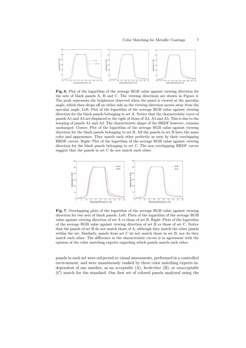
Fig. 6. Plot of the logarithm of the average RGB value against viewing direction forthe sets of black panels A, B and C. The viewing directions are shown in Figure 4.The peak represents the brightness observed when the panel is viewed at the specularangle, which then drops o! on either side as the viewing direction moves away from thespecular angle. Left: Plot of the logarithm of the average RGB value against viewingdirection for the black panels belonging to set A. Notice that the characteristic curve ofpanels A1 and A3 are displaced to the right of those of A2, A4 and A5. This is due to thewarping of panels A1 and A3. The characteristic shape of the BRDF however, remainsunchanged. Center: Plot of the logarithm of the average RGB value against viewingdirection for the black panels belonging to set B. All the panels in set B have the samecolor and appearance. They match each other perfectly as seen by their overlappingBRDF curves. Right: Plot of the logarithm of the average RGB value against viewingdirection for the black panels belonging to set C. The non overlapping BRDF curvessuggest that the panels in set C do not match each other.
0 5 10 15 20 25 30 35 40 45 500
50
100
150
200
250
300
Viewing Direction 0!50
Inte
nsi
ty 0
!2
55
Set A
Set B
0 5 10 15 20 25 30 35 40 45 500
50
100
150
200
250
300
Viewing Direction 0!50
Inte
nsi
ty 0
!2
55
Set B
Set C
Fig. 7. Overlapping plots of the logarithm of the average RGB value against viewingdirection for two sets of black panels. Left: Plots of the logarithm of the average RGBvalue against viewing direction of set A vs those of set B. Right: Plots of the logarithmof the average RGB value against viewing direction of set B vs those of set C. Noticethat the panels of set B do not match those of A, although they match the other panelswithin the set. Similarly, panels from set C do not match those in set B, nor do theymatch each other. The di!erence in the characteristic curves is in agreement with theopinion of the color matching experts regarding which panels match each other.
panels in each set were subjected to visual assessments, performed in a controlledenvironment, and were unanimously ranked by three color matching experts in-dependent of one another, as an acceptable (A), borderline (B), or unacceptable(C) match for the standard. Our first set of colored panels analyzed using the
8 Jayant Silva and Kristin J. Dana
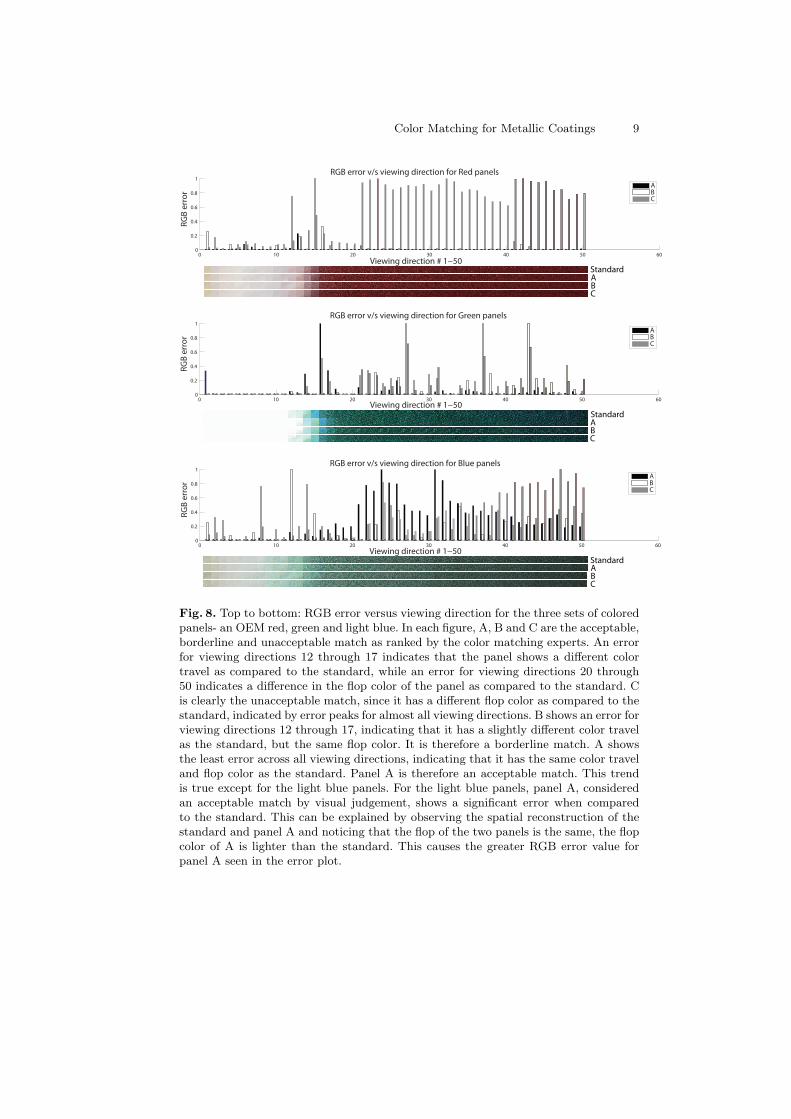
Texcam is the metallic red color. Figure 8 shows a plot of the RGB error ver-sus viewing angle. Panel C is clearly an unacceptable match and shows a largeerror across most of the viewing directions. Visual evaluation confirms that itis indeed appears darker than the standard on flop. The error in viewing di-rections 12 through 15 for Panel B indicates that the color travel from light todark occurs slightly later as compared to the standard. Panel B can thereforebe considered as a borderline match.Panel A shows negligible error across allviewing directions, indicating that it has the correct color and travel, and so isan acceptable match for the standard.
The second set of panels is a metallic green color. Panel A and B show asignificant error in viewing directions 14 through 17. This indicates that the colortravel for these panels slightly di!ers from the standard. Apart from this minordi!erence in the color travel, panel A does not show a significant error for the flopcolor and is an acceptable match when compared to the color standard. PanelB shows some error in flop color for a few viewing directions and is therefore aborderline match for the color standard. Panel C shows the same color travel asthe standard, which is reflected in the insignificant error for viewing directions14 through 17. Panel C does however, show a significant error between viewingdirections 20 through 50, indicating that it does not match the color standardin its flop color. Panel C is therefore an unacceptable match for the standard.
The third set of panels is a metallic light blue. Panel A shows a large errorfor viewing directions 20 through 50, This indicates a mismatch in flop color.Visual evaluation confirms this, with panel A being lighter in color as comparedto the standard. The error plot for viewing directions 12 through 15 howeverindicates that it does show the same color travel. Panel B shows an error inviewing directions 12 through 15 indicating a slight di!erence in color travelfrom light to dark. It also does not show a large error in viewing directions 20through 50, indicating that it is similar in flop color to the standard. Panel Bcan therefore be regarded a borderline match. Panel C shows a large error in flopcolor, which can clearly be seen by noticing the error plot for Panel C betweenviewing directions 20 through 50. Panel C is therefore an acceptable match forthe color standard.
4 Discussion and Implications
A completely automated and objective matching technique for automotive coat-ings has been developed using the texture camera. The texture camera was usedto reconstruct a 5mm!5mm patch of each of the panels as seen from 50 di!erentviewing directions. The di!erent views of the patch were then put together toform a composite spatial reconstruction. The precise color travel of the coating,as well as it appearance based characteristics such as the orange peel, primaryspecularity and sparkle due to the flakes were all be observed in simultaneouslyin the composite spatial reconstruction. This image also makes it possible toquantify the color travel of the coating as its BRDF and match the panels basedon their BRDF. These matches produced by the Texcam were shown to have a
Color Matching for Metallic Coatings 9
0 10 20 30 40 50 600
0.2
0.4
0.6
0.8
1RGB error v/s viewing direction for Red panels
RG
B e
rro
r
Viewing direction # 1!50
ABC
0 10 20 30 40 50 600
0.2
0.4
0.6
0.8
1
RGB error v/s viewing direction for Green panels
RG
B e
rro
r
Viewing direction # 1!50
ABC
0 10 20 30 40 50 600
0.2
0.4
0.6
0.8
1RGB error v/s viewing direction for Blue panels
RG
B e
rro
r
Viewing direction # 1!50
ABC
Standard
Standard
StandardABC
ABC
ABC
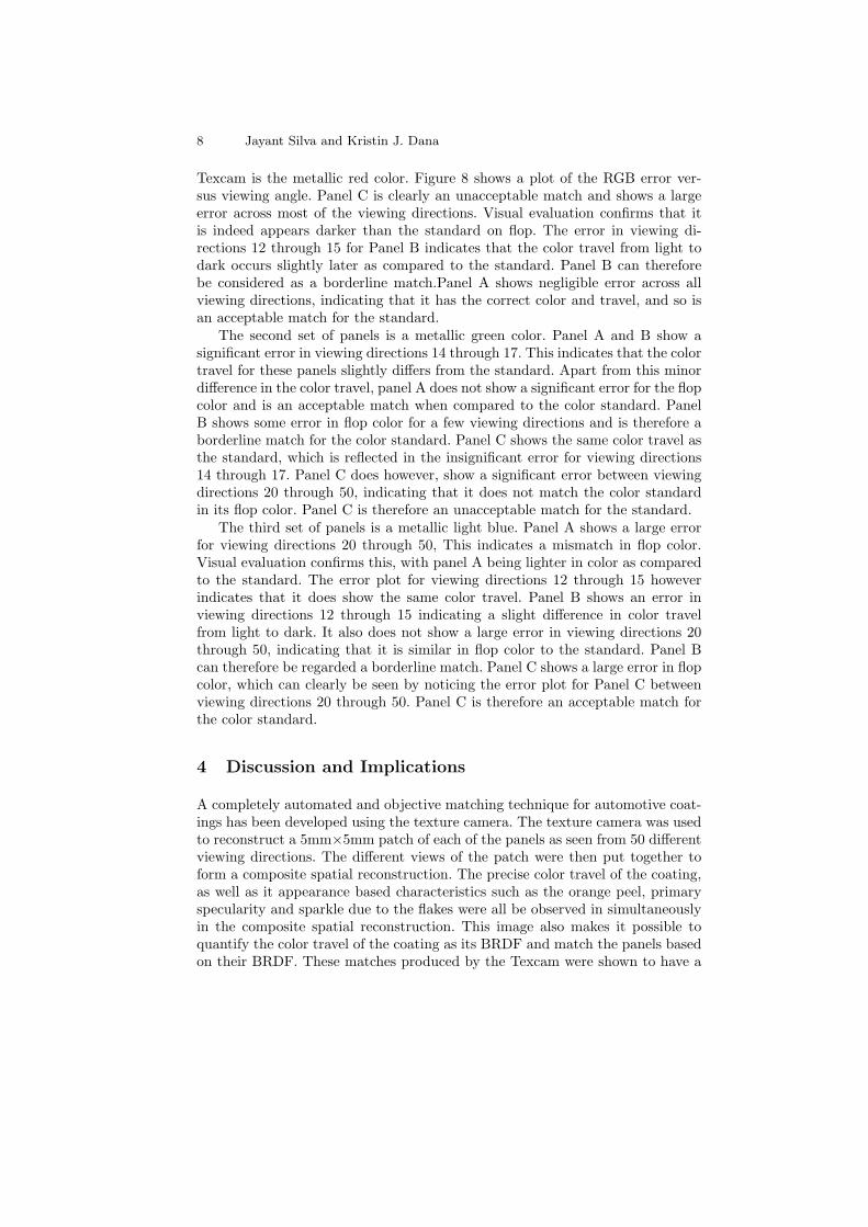
Fig. 8. Top to bottom: RGB error versus viewing direction for the three sets of coloredpanels- an OEM red, green and light blue. In each figure, A, B and C are the acceptable,borderline and unacceptable match as ranked by the color matching experts. An errorfor viewing directions 12 through 17 indicates that the panel shows a di!erent colortravel as compared to the standard, while an error for viewing directions 20 through50 indicates a di!erence in the flop color of the panel as compared to the standard. Cis clearly the unacceptable match, since it has a di!erent flop color as compared to thestandard, indicated by error peaks for almost all viewing directions. B shows an error forviewing directions 12 through 17, indicating that it has a slightly di!erent color travelas the standard, but the same flop color. It is therefore a borderline match. A showsthe least error across all viewing directions, indicating that it has the same color traveland flop color as the standard. Panel A is therefore an acceptable match. This trendis true except for the light blue panels. For the light blue panels, panel A, consideredan acceptable match by visual judgement, shows a significant error when comparedto the standard. This can be explained by observing the spatial reconstruction of thestandard and panel A and noticing that the flop of the two panels is the same, the flopcolor of A is lighter than the standard. This causes the greater RGB error value forpanel A seen in the error plot.
10 Jayant Silva and Kristin J. Dana
high correlation with the professional judgement of the color matching experts.Furthermore, the analysis and matching of a metallic coating by the Texcamis extremely fast - the imaging of the surface from 50 di!erent viewing direc-tions and the subsequent comparison is achieved in under 15 seconds. The largenumber of viewing directions that can simultaneously be imaged by the Texcammakes it superior to a conventional multi angle spectrophotometer. Metallic ef-fect pigments that contain aluminum or mica flakes as well as newer families ofpigments like Xirallic exhibit an intense sparkle when viewed under direct sun-light. This sparkle can neither be captured nor su"ciently characterized withtraditional multi- angle spectrophotometers [12]. Also, unlike the conventionalmulti- angle spectrophotometer, the color travel information obtained using thetexcam is independent of the orientation of the panel [11]. These features of theTexcam make it a potential viable solution for automated matching of metallicflake finishes.
References
1. Besold, R.: Metallic e!ect - characterization, parameter and methods for instru-mental determination. Die Farbe (1990) 79–85
2. Gunter Buxbaum, e. Industrial Inorganic Pigments (1993)3. McCamy, C.S.: Observation and measurement of the appearance of metallic mate-
rials. part i. macro appearance. COLOR research and application (1996) 292–3044. Rodrigues, A.: Color technology and paint. Color and Paints Interim Meeting of
the International Color Association Proceedings (2004) 103–1085. Ershova, S., Kolchina, K., Myszkowskib, K.: Rendering pearlescent appearance
based on paint-composition modelling. The European Association for ComputerGraphics 22th Annual Conference: EUROGRAPHICS 2001 20(3) (2001) 227–238
6. Dana, K., Wang, J.: Device for convenient measurement of spatially varying bidi-rectional reflectance. Journal of the Optical Society of America (2004) 1–12
7. Dana, K., Wang, J.: A novel approach for texture shape recovery. InternationalConference on Computer Vision (2003) 1374–1380
8. Dana, K.: Brdf/btf measurement device. International Conference on ComputerVision (2001) 460–466
9. Westlund, H.B., Meyer, G.W.: Applying appearance standards to light reflectionmodels. Proceedings of the 28th annual conference on Computer graphics andinteractive techniques (2001) 501 – 510
10. Li, H., Foo, S.C., Torrance, K.E., Westin, S.H.: Automated three-axis goniore-flectometer for computer graphics applications. Advanced Characterization Tech-niques for Optics, Semiconductors, and Nanotechnologies II, Proc. SPIE 5878(2005)
11. Davis, D.J.: An investigation of multi angle spectrophotometry for coloredpolypropylene compounds. SPE/ ANTEC Proceedings (1996) 2663–2671
12. Streitberger, H.J., Dossel, K.F.: Automotive paints and coatings. (2008) 404