Embed Size (px)
Citation preview
Color Mark SensorsE3S-DC/E3NX-CA Series
Color Mark Detection on Any Type of Packaging
Color Mark Photoelectric SensorE3S-DC
• Able to handle glossy materials
• Able to detect subtle color differences
• Stable even when lots change
Color Fiber Amplifier UnitE3NX-CA

2 Color Mark Sensors
Packaging Comes in a Variety of Designs and MaterialsPackaging materials and designs have become more diverse, incorporating aluminum vapor deposition material to prevent oxidation, and bold, bright colors to attract the attention of consumers.
More and more people working with color mark detection require:
If we don’t respond to packaging trends, the number of
increase, reducing productivity...
Highly-reflective glossy packaging withaluminum vapor deposition material
Colorful packaging where there is little dierence in color between the mark and background
Low-reflection packaging, such as film with fine asperities
Food/Beverage/
Personal Care Industries
n t
Cookie
Business Challenge
• Stable detection of aluminum vapor deposition material and other glossy packaging.
• Stable detection of colorful packaging with little color difference.
• Stable detection of packaging even if the lot changes.
false detections with color mark sensors will
3
Packaging Comes in a Variety of Designs and MaterialsPackaging materials and designs have become more diverse, incorporating aluminum vapor deposition material to prevent oxidation, and bold, bright colors to attract the attention of consumers.
More and more people working with color mark detection require:
If we don’t respond to packaging trends, the number of
increase, reducing productivity...
Highly-reflective glossy packaging withaluminum vapor deposition material
Colorful packaging where there is little dierence in color between the mark and background
Low-reflection packaging, such as film with fine asperities
Food/Beverage/
Personal Care Industries
n t
Cookie
Business Challenge
• Stable detection of aluminum vapor deposition material and other glossy packaging.
• Stable detection of colorful packaging with little color difference.
• Stable detection of packaging even if the lot changes.
false detections with color mark sensors will
Color Mark Photoelectric SensorE3S-DC
NEW
Color Fiber Amplifier UnitE3NX-CA
NEW
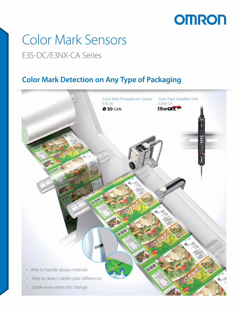
The Sensors can accurately detect color marks on glossy and colorful packaging, which have been troublesome for conventional systems.They also help reduce the number of troubleshooting requests made to packaging machine manufacturers—without any decrease in the operations rate due to equipment stoppages caused by false detection.
OMRON’s New Color Mark Sensors
ODetectionof Both Glossy andColorful Packaging.
Color Mark Photoelectric SensorE3S-DC
NEW
Color Fiber Amplifier UnitE3NX-CA
NEW
The Sensors can accurately detect color marks on glossy and colorful packaging, which have been troublesome for conventional systems.They also help reduce the number of troubleshooting requests made to packaging machine manufacturers—without any decrease in the operations rate due to equipment stoppages caused by false detection.
OMRON’s New Color Mark Sensors
ODetectionof Both Glossy andColorful Packaging.
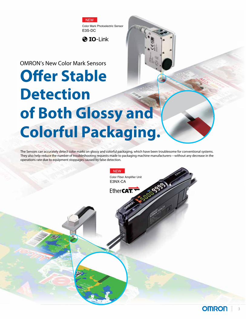
The intensity of the light received by the
is too high, so there is not enough
mark detection (i.e. saturation, Fig. 1).
saturation and allow the sensor to detect the
mark. However, if the sensor is tilted too
much, detection becomes unstable as the
incident light level decreases (Fig. 2).
Exis
ting
chal
leng
es
E3S-DC/E3NX-CA
Light Is Received over a Wide Range: Ideal for
This allows for the stable detection of glossy aluminum vapor deposition packaging—simply install the Sensor directly above
“I want stable detection of aluminum vapor deposition material and other glossy packaging.”
Follow along to see how the technology works.
Incident level
Saturated; unable to detect
Insucient light; unable to detec tFine adjustment of light intensity (tilt) required
Threshold
Incident level
Threshold
Background
Background
Mark
Mark
(Fig. 1)
(Fig. 2)
Glossy packaging
Sensor
Glossy packaging
S
Sensor
e
ackground Mark
ble detection of glossy alu—simply install the Sensor
Glossy Packaging
4 Color Mark Sensors
The intensity of the light received by the
is too high, so there is not enough
mark detection (i.e. saturation, Fig. 1).
saturation and allow the sensor to detect the
mark. However, if the sensor is tilted too
much, detection becomes unstable as the
incident light level decreases (Fig. 2).
Exis
ting
chal
leng
es
E3S-DC/E3NX-CA
Light Is Received over a Wide Range: Ideal for
This allows for the stable detection of glossy aluminum vapor deposition packaging—simply install the Sensor directly above
“I want stable detection of aluminum vapor deposition material and other glossy packaging.”
Follow along to see how the technology works.
Incident level
Saturated; unable to detect
Insucient light; unable to detec tFine adjustment of light intensity (tilt) required
Threshold
Incident level
Threshold
Background
Background
Mark
Mark
(Fig. 1)
(Fig. 2)
Glossy packaging
Sensor
Glossy packaging
S
Sensor
e
ackground Mark
ble detection of glossy alu—simply install the Sensor
Glossy Packaging
Grayscale
Further Information
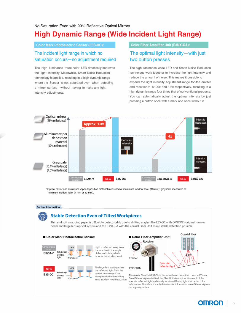
No Saturation Even with 99% Reflective Optical Mirrors
High Dynamic Range (Wide Incident Light Range)
The high luminance three-color LED drastically improvesthe light intensity. Meanwhile, Smart Noise Reduction technology is applied, resulting in a high dynamic rangewhere the Sensor is not saturated even when detectinga mirror surface—without having to make any light intensity adjustments.
The high luminance white LED and Smart Noise Reduction technology work together to increase the light intensity and reduce the amount of noise. This makes it possible to expand the light intensity adjustment range for the emitter and receiver to 1/100x and 1/3x respectively, resulting in a high dynamic range four times that of conventional products. You can automatically adjust the optimal intensity by just pressing a button once with a mark and once without it.
Stable Detection Even of Tilted Workpieces
:tinU reifilpmA rebiF roloC:rosneS cirtceleotohP kraM roloC
The large lens easily gathersthe reflected light from the narrow beam even if the workpiece is tilted resulting in no incident level fluctuation.
The coaxial Fiber Unit E32-C91N has an emission beam that covers a 60° area. Even if the workpiece is tilted, the Fiber Unit does not receive much of the specular reflected light and mainly receives diusion light that carries color information. Therefore, it stably detects color information even if the workpiece has a glossy surface.
E3ZM-V
E3S-DC
E32-C91N
Receiver
E32-C91N
Receiver
Approx. 1.3x
* Optical mirror and aluminum vapor deposition material measured at maximum incident level (13 mm); grayscale measured at minimum incident level (7 mm or 13 mm).
Optical mirror
Aluminum vapor deposition
material
4x
Lens
Emitted light Workpiece
Lens
Emitted light Workpiece
Color Fiber Amplifier Unit (E3NX-CA):
Constantintensity
Intensity decreases
Intensity increases
Coaxial fiber
Specular reflected light
Receiver
Emitter
Receiver
60°60°
NEWE3X-DAC-S E3NX-CANEWConventional product
Conventional product
Conventional productE3ZM-V E3S-DC
NEW
The incident light range in which no saturation occurs—no adjustment required
The optimal light intensity—with just two button presses
Color Mark Photoelectric Sensor (E3S-DC):
Thin and soft wrapping paper is dicult to detect stably due to shifting angles. The E3S-DC with OMRON's original narrow beam and large lens optical system and the E3NX-CA with the coaxial Fiber Unit make stable detection possible.
Light is reflected away from the lens due to the angle of the workpiece, which reduces the incident level. Emitter
5
Exis
ting
chal
leng
es
With designs becoming more colorful,
there are times where there is little
and the design elements (background).
When color dierences are subtle,
dierence in color between the mark
the S/N ratio*1 required for detection
cannot be obtained, and the color mark
cannot be detected (Fig. 1).
E3S-DC/E3NX-CA
Provides a High S/N Ratio to Detect Subtle Color Differences
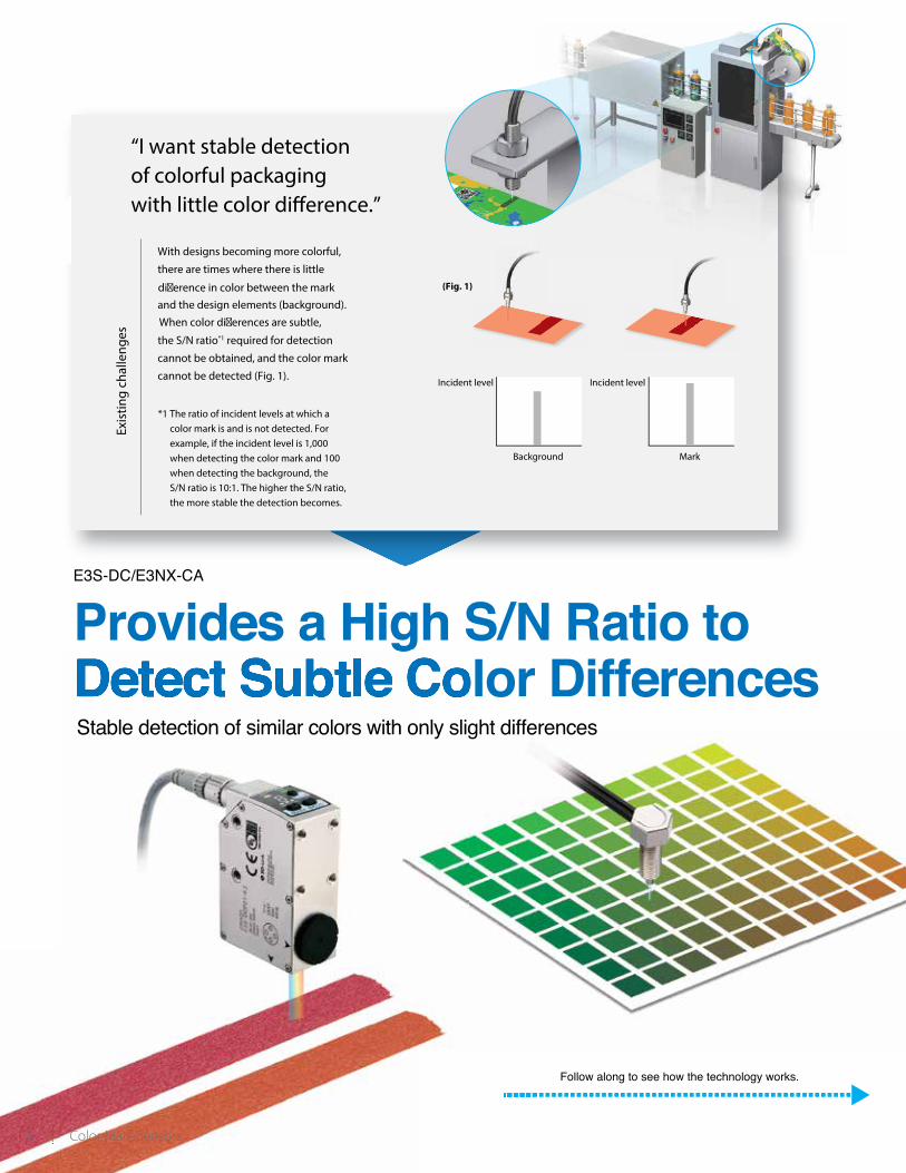
“I want stable detection of colorful packaging
(Fig. 1)
Incident level Incident level
Background Mark
Follow along to see how the technology works.
*1 The ratio of incident levels at which a color mark is and is not detected. For example, if the incident level is 1,000 when detecting the color mark and 100 when detecting the background, the S/N ratio is 10:1. The higher the S/N ratio, the more stable the detection becomes.
Stable detection of similar colors with only slight differences
6 Color Mark Sensors
Exis
ting
chal
leng
es
With designs becoming more colorful,
there are times where there is little
and the design elements (background).
When color dierences are subtle,
dierence in color between the mark
the S/N ratio*1 required for detection
cannot be obtained, and the color mark
cannot be detected (Fig. 1).
E3S-DC/E3NX-CA
Provides a High S/N Ratio to Detect Subtle Color Differences
“I want stable detection of colorful packaging
(Fig. 1)
Incident level Incident level
Background Mark
Follow along to see how the technology works.
*1 The ratio of incident levels at which a color mark is and is not detected. For example, if the incident level is 1,000 when detecting the color mark and 100 when detecting the background, the S/N ratio is 10:1. The higher the S/N ratio, the more stable the detection becomes.
Stable detection of similar colors with only slight differences
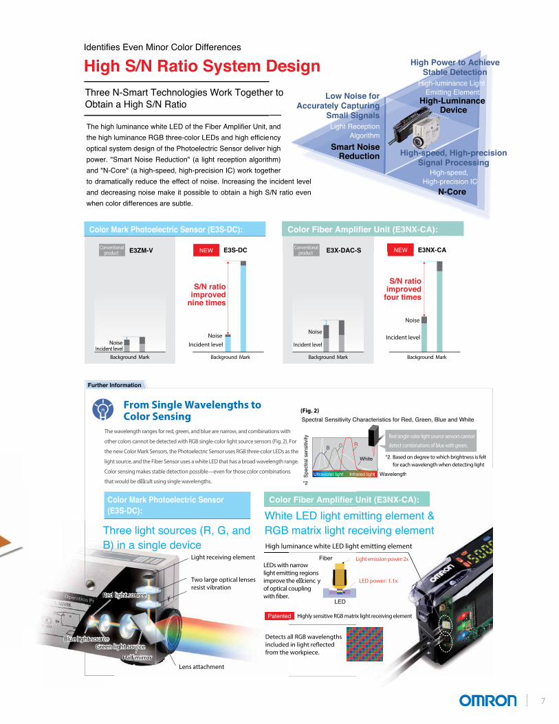
Identifies Even Minor Color Differences
High S/N Ratio System Design
*2
(Fig. 2)
Three N-Smart Technologies Work Together to Obtain a High S/N Ratio
Color Fiber Amplifier Unit (E3NX-CA):
White LED light emitting element & RGB matrix light receiving element
Patented
Fiber
LED
The high luminance white LED of the Fiber Amplifier Unit, and the high luminance RGB three-color LEDs and high efficiency optical system design of the Photoelectric Sensor deliver high power. "Smart Noise Reduction" (a light reception algorithm) and "N-Core" (a high-speed, high-precision IC) work together to dramatically reduce the effect of noise. Increasing the incident level and decreasing noise make it possible to obtain a high S/N ratio even when color differences are subtle.
*2. Based on degree to which brightness is felt for each wavelength when detecting light
Spectral Sensitivity Characteristics for Red, Green, Blue and White
Wavelength
White
Spec
tral s
ensi
tivity Red single color light source sensors cannot
detect combinations of blue with green.
Infrared lightUltraviolet light
RGB
Unit (E3NX-CA):
mitting element & eceiving element
Wavelengthared light
RGB
Patented
Light receiving element
Lens attachmentHalf mirrorHalf mirror
Two large optical lenses resist vibration
Red light source
Blue light sourceGreen light source
Red light source
Blue light sourceGreen light source
Detects all RGB wavelengthsincluded in light reflected from the workpiece.
Further Information
From Single Wavelengths to Color Sensing
The wavelength ranges for red, green, and blue are narrow, and combinations with
other colors cannot be detected with RGB single-color light source sensors (Fig. 2). For
the new Color Mark Sensors, the Photoelectric Sensor uses RGB three-color LEDs as the
light source, and the Fiber Sensor uses a white LED that has a broad wavelength range.
Color sensing makes stable detection possible—even for those color combinations
that would be dicult using single wavelengths.
Color Mark Photoelectric Sensor (E3S-DC):
Three light sources (R, G, and B) in a single device
Color Mark Photoelectric Sensor (E3S-DC): Color Fiber Amplifier Unit (E3NX-CA):
NEWConventional product E3ZM-V E3S-DC NEWE3X-DAC-S E3NX-CA
Noise
Background Mark Background Mark Background Mark Background MarkIncident level
S/N ratio improved
nine times
NoiseIncident level
Noise
Incident level
Noise
Incident level
S/N ratio improved
four times
Designr to
andncy
high hm)ther incident level/N ratio even
Color Fiber Amplifier Unit (E3NX-CA):
NEWE3X-DAC-S E3NX-CA
Smart Noise Reduction
High-speed, High-precision IC
High-Luminance Device
High-speed, High-precisionSignal Processing
High-luminance Light Emitting ElementLow Noise for
Accurately Capturing Small Signals
Light Reception Algorithm
High Power to AchieveStable Detection
N-Core
Conventional product
High luminance white LED light emitting element
LEDs with narrow light emitting regionsimprove the ecienc yof optical couplingwith fiber.
Light emission power: 2x
LED power: 1.1x
Highly sensitive RGB matrix light receiving element
7
Lot A
Lot C
E3S-DC/E3NX-CA
Visualization of Printed Color Variation Makes Troubleshooting Easier Allows support of package print color variation – and helps reduce downtime
Follow along to see how the technology works.
Set threshold
False detection byexceeding set threshold
Lot A Lot B Lot C
R: 2350G: 2080B: 830
R: 1780G: 1570B: 580
Exis
ting
chal
leng
es
Packaging materials may vary from lot to lot.
If the sensor parameters are not changed, this
could result in equipment stoppage
caused by false detection. In such a case, it can be dicult to determine the cause
of the problem—resulting in time lost
due to troubleshooting and a notable
decrease in productivity.
“I want stable detection of packaging even if the lot changes.”
Incident level
Background Mark Background Mark Background Mark
8 Color Mark Sensors
Lot A
Lot C
E3S-DC/E3NX-CA
Visualization of Printed Color Variation Makes Troubleshooting Easier Allows support of package print color variation – and helps reduce downtime
Follow along to see how the technology works.
Set threshold
False detection byexceeding set threshold
Lot A Lot B Lot C
R: 2350G: 2080B: 830
R: 1780G: 1570B: 580
Exis
ting
chal
leng
es
Packaging materials may vary from lot to lot.
If the sensor parameters are not changed, this
could result in equipment stoppage
caused by false detection. In such a case, it can be dicult to determine the cause
of the problem—resulting in time lost
due to troubleshooting and a notable
decrease in productivity.
“I want stable detection of packaging even if the lot changes.”
Incident level
Background Mark Background Mark Background Mark
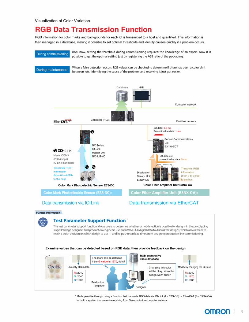
RGB Data Transmission Function RGB information for color marks and backgrounds for each lot is transmitted to a host and quantified. This information is then managed in a database, making it possible to set optimal thresholds and identify causes quickly if a problem occurs.
Visualization of Color Variation
Further Information
Test Parameter Support Function *1The test parameter support function allows users to determine whether or not detection is possible for designs in the prototyping stage. Package designers and production engineers use quantified RGB digital data to discuss the designs, which allows them toreach a quick decision on which design to use — and helps shorten lead times from design to production line commissioning.
Sensor CommunicationsUnitE3NW-ECTNX Series
IO-LinkMaster UnitNX-ILM400
Database
Controller (PLC)
HMI
SenUnitE3N
Computer network
Fieldbus network
Until now, setting the threshold during commissioning required the knowledge of an expert. Now it is possible to get the optimal setting just by registering the RGB ratio of the packaging.
When a false detection occurs, RGB values can be checked to determine if there has been a color shift between lots. Identifying the cause of the problem and resolving it just got easier.
During commissioning
During maintenance
Transmits RGB information (from 0 to 4,095) to the host
Color Mark Photoelectric Sensor (E3S-DC): Color Fiber Amplifier Unit (E3NX-CA):
Data transmission via EtherCATData transmission via IO-Link
Meets COM3 (230.4 kbps) IO-Link standards
Examine values that can be detected based on RGB data, then provide feedback on the design.
Quantify RGB data
RGB quantitative value database
R: 2040G: 2040B: 1930
Modify by changing the G value
R: 2040G: 1970B: 1930
The mark can be detected if the G value is 1970, right?
Changing this color will be okay, since the design won't suffer!
Production engineer Designer
Color Mark Photoelectric Sensor E3S-DC
Distributed Sensor UnitE3NW-DS
edUnitDS
Color Fiber Amplifier Unit E3NX-CA
*1 Made possible through using a function that transmits RGB data via IO-Link (for E3S-DS) or EtherCAT (for E3NX-CA) to build a system that covers everything from Sensors to the computer network.
I/O data: 0.2 msPresent value data: 1 ms
I/O data and present value data: 5 ms
Transmits RGB information (from 0 to 9,999) to the host
Cookie
9

10
MEMO

11
Color Mark Photoelectric Sensor
E3S-DCColor Mark Detection on Any Type of Packaging.• Narrow Beam and large lens for stable detection of workpieces tilted at various angles. • Detects subtle color differences.• High luminance, three-element (RGB) LED light source for
greater light intensity. • Highly efficient optics technology provides high power and enables stable detection even of subtle color differences. • Handles glossy workpieces.• Thorough noise reduction.• High dynamic range covers everything from black to mirror surfaces.• IoT compatible.• Models that support IO-Link also available.• Sends RGB information to host with high-speed IO-Link communications.
• Optimum threshold set to reduce false detection.
Ordering InformationSensors (Refer to Dimensions on page 18.)
Note: Download the IO-Link setup file (IODD file) from your OMRON website.* Refer to Ratings and Specifications on page 13 for the baud rate.
Accessories (Sold Separately)Sensor I/O Connectors (Required for a Sensor with a connector.)Connectors are not provided with the Sensors. Be sure to order a Connector separately.
Note: 1. Refer to Sensor I/O Connectors/Sensor Controllers on your OMRON website for details. The XS2W (Socket and Plug on Cable Ends) and XS5F (Socket on One Cable End) are also available.
2. The connectors will not rotate after they are connected.There are also straight type/L-shape type combinations available.
Sensing method Appearance Connection method Sensing distance Output Model Baud rate *
Diffuse-reflective (mark detection) M12 connector
Push-pullE3S-DCP21-IL2 COM2
E3S-DCP21-IL3 COM3
NPN E3S-DCN21 ---
For the most recent information on models that have been certified for safety standards, refer to your OMRON website.
Refer to Safety Precautions on page 17.
Red light, Green light, Blue light
10±3 mm
Size Type Appearance Cable length Model
M12
Socket on one cable end
2 m XS2F-D421-D80-F
5 m XS2F-D421-G80-F
*22 m XS2F-D422-D80-F
5 m XS2F-D422-G80-F
Socket and plug on cable ends *1
2 m XS5W-D421-D81-F
5 m XS5W-D421-G81-F
* 22 m XS5W-D422-D81-F
5 m XS5W-D422-G81-F
Straight
L-shape
Smartclick connectorStraight/straight
Smartclick connectorL-shape/L-shape
12
E3S-DC
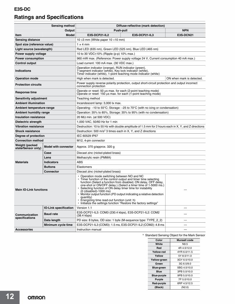
Ratings and SpecificationsSensing method Diffuse-reflective (mark detection)
Output Push-pull NPNItem Model E3S-DCP21-IL2 E3S-DCP21-IL3 E3S-DCN21Sensing distance 10 ±3 mm (White paper 10 ×10 mm)Spot size (reference value) 1 × 4 mmLight source (wavelength) Red LED (635 nm), Green LED (525 nm), Blue LED (465 nm)Power supply voltage 10 to 30 VDC±10% (Ripple (p-p) 10% max.)Power consumption 960 mW max. (Reference: Power supply voltage 24 V, Current consumption 40 mA max.)Control output Load current: 100 mA max. (30 VDC max.)
IndicationsOperation indicator (orange), RUN indicator (green),7-segment indicator (white), Key lock indicator (white),Timer indicator (white), 1-point teaching mode indicator (white)
Operation mode NO.detceted si kram nehw hgiH when mark is detected.
Protection circuits Power supply reverse polarity protection, output short-circuit protection and output incorrect connection protection
Response time Operate or reset: 50 µs max. for each (2-point teaching mode)Operate or reset: 150 µs max. for each (1-point teaching mode)
Sensitivity adjustment Teaching methodAmbient illumination Incandescent lamp: 3,000 lx max.Ambient temperature range Operating: −10 to 55°C; Storage: −25 to 70°C (with no icing or condensation)Ambient humidity range Operation: 35% to 85%, Storage: 35% to 95% (with no condensation)Insulation resistance 20 MΩ min. (at 500 VDC)Dielectric strength 1,000 VAC, 50/60 Hz for 1 minVibration resistance Destruction: 10 to 55 Hz with double amplitude of 1.5 mm for 2 hours each in X, Y, and Z directionsShock resistance Destruction: 500 m/s2 3 times each in X, Y, and Z directionsDegree of protection IEC 60529 IP67Connection method M12, 4-pin connectorWeight (packed state/Sensor only) Model with connector Approx. 370 g/approx. 320 g
Materials
Case Diecast zinc (nickel-plated brass)Lens Methacrylic resin (PMMA)Indicators ABSButtons ElastomersConnector Diecast zinc (nickel-plated brass)
Main IO-Link functions
• Operation mode switching between NO and NC• Timer function of the control output and timer time selecting
function (Select a function from disabled, ON delay, OFF delay, one-shot or ON/OFF delay.) (Select a timer time of 1-5000 ms.)
• Selecting function of ON delay timer time for instability (0 (disabled)-1000 ms)
• Monitor output function (PD output indicating a relative detection quantity)
• Energizing time read-out function (unit: h)• Initialize the settings function “Restore the factory settings”
---
Communication specifications
IO-Link specification Version 1.1 ---
Baud rate E3S-DCP21-IL3: COM3 (230.4 kbps), E3S-DCP21-IL2: COM2 (38.4 kbps) ---
Data length PD size: 8 bytes, OD size: 1 byte (M-sequence type: TYPE_2_2) ---Minimum cycle time E3S-DCP21-IL3 (COM3): 1.5 ms, E3S-DCP21-IL2 (COM2): 4.8 ms ---
Accessories ---launam noitcurtsnI
* Standard Sensing Object for the Mark SensorColor Munsell codeWhite N9.5Red 4R 4.5/12.0
Yellow-red 4YR 6.0/11.5Yellow 5Y 8.5/11.0
Yellow-green 3GY 6.5/10.0Green 3G 6.5/9.0
Blue-green 5BG 4.5/10.0Blue 3PB 5.0/10.0
Blue-purple 9PB 5.0/10.0Purple 7P 5.0/10.0
Red-purple 6RP 4.5/12.5(Black) (N2.0)
E3S-DC

13
E3S-DC
Engineering Data (Reference Value)Color vs. Detection CapabilityE3S-DC
Note: The above chart shows the combinations of colors for which teaching is possible at a sensing distance of 10 mm.
Detectable RangesE3S-DC
o
Teaching CapabilitiesWhite
White
RedYellow-red
Red Yellow-red Yellow
Yellow
Yellow-green
Yellow-green
Green
Green
Blue-green
Blue-green
Blue
Blue
Blue-purple Purple Red
-purple Black
Blue-purplePurple
Red-purpleBlack
15.0
14.0
13.0
12.0
11.0
10.0
9.0
8.0
7.0
6.0
5.0
Teaching distance: 10 mmBackground color: White
Det
ecta
ble
rang
e (m
m)
RedYell
ow-red Yellow
Yellow-
green
Green
Blue-g
reen
Blue
Blue-p
urple
Purple
Red-pu
rple Black
15.0
14.0
13.0
12.0
11.0
10.0
9.0
8.0
7.0
6.0
5.0
Teaching distance: 10 mmBackground color: Red
White
Yellow-
red Yellow
Yellow-
green
Green
Blue-g
reen
Blue
Blue-p
urple
Purple
Red-pu
rple Black
Det
ecta
ble
rang
e (m
m) 15.0
14.0
13.0
12.0
11.0
10.0
9.0
8.0
7.0
6.0
5.0
Teaching distance: 10 mmBackground color: Yellow-red
White Red Yellow
Yellow-
green
Green
Blue-g
reen
Blue
Blue-p
urple
Purple
Red-pu
rple Black
Det
ecta
ble
rang
e (m
m)
15.0
14.0
13.0
12.0
11.0
10.0
9.0
8.0
7.0
6.0
5.0
Teaching distance: 10 mmBackground color: Yellow
Det
ecta
ble
rang
e (m
m)
White Red
Yellow-
redYell
ow-gre
enGre
enBlu
e-gree
nBlu
eBlu
e-purp
lePur
pleRed
-purple Bla
ck
15.0
14.0
13.0
12.0
11.0
10.0
9.0
8.0
7.0
6.0
5.0
Teaching distance: 10 mmBackground color: Yellow-green
White Red
Yellow-
red Yellow
Green
Blue-g
reen
Blue
Blue-p
urple
Purple
Red-pu
rple Black
Det
ecta
ble
rang
e (m
m) 15.0
14.0
13.0
12.0
11.0
10.0
9.0
8.0
7.0
6.0
5.0
Teaching distance: 10 mmBackground color: Green
Det
ecta
ble
rang
e (m
m)
White Red
Yellow-
red Yellow
Yellow-
green
Blue-g
reen
Blue
Blue-p
urple
Purple
Red-pu
rple Black
15.0
14.0
13.0
12.0
11.0
10.0
9.0
8.0
7.0
6.0
5.0
Teaching distance: 10 mmBackground color: Blue-green
Det
ecta
ble
rang
e (m
m)
White Red
Yellow-
red Yellow
Yellow-
green
Green Blue
Blue-p
urple
Purple
Red-pu
rple Black
15.0
14.0
13.0
12.0
11.0
10.0
9.0
8.0
7.0
6.0
5.0
Teaching distance: 10 mmBackground color: Blue
White Red
Yellow-
red Yellow
Yellow-
green
Green
Blue-g
reen
Blue-p
urple
Purple
Red-pu
rple Black
Det
ecta
ble
rang
e (m
m) 15.0
14.0
13.0
12.0
11.0
10.0
9.0
8.0
7.0
6.0
5.0
Teaching distance: 10 mmBackground color: Blue-purple
Det
ecta
ble
rang
e (m
m)
White Red
Yellow-
red Yellow
Yellow-
green
Green
Blue-g
reen
Blue
Purple
Red-pu
rple Black
E3S-DC
14
E3S-DC
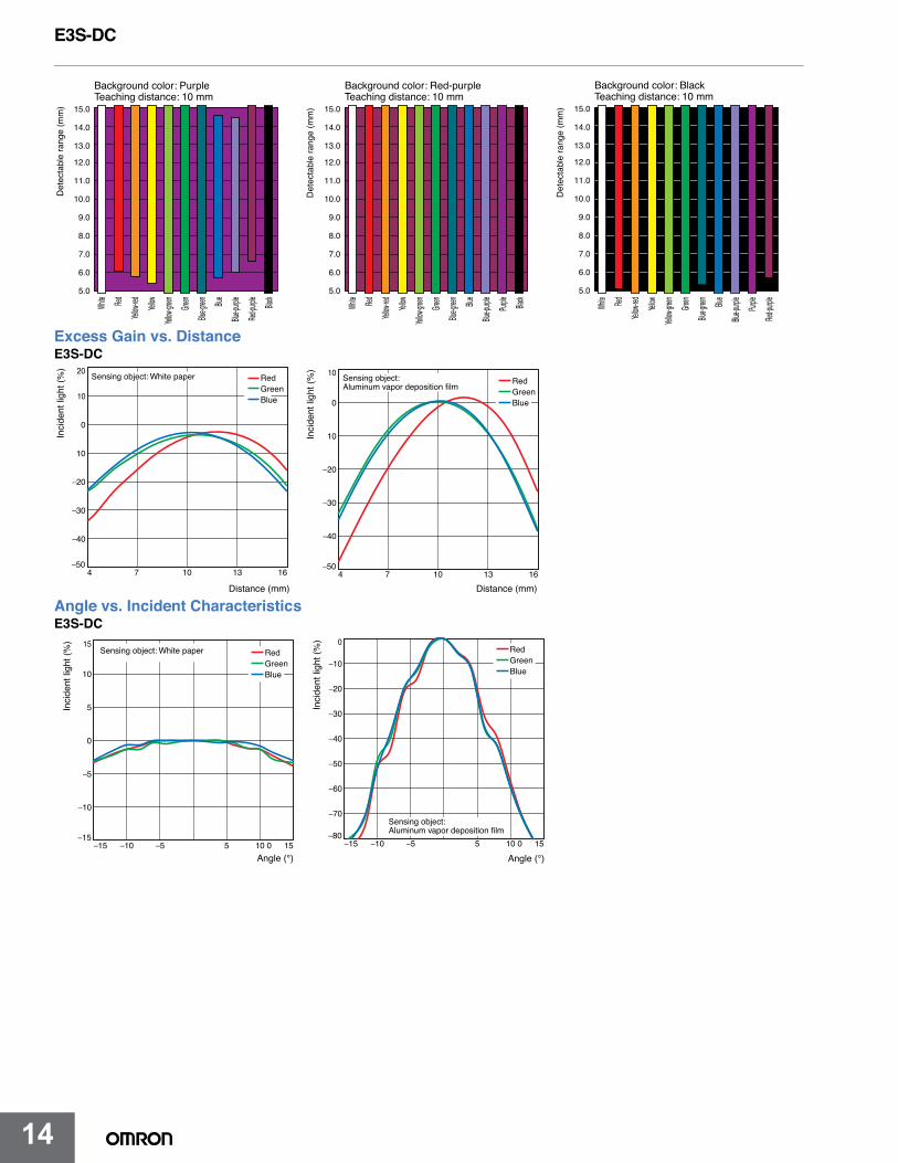
Excess Gain vs. DistanceE3S-DC
Angle vs. Incident CharacteristicsE3S-DC
15.0
14.0
13.0
12.0
11.0
10.0
9.0
8.0
7.0
6.0
5.0
Teaching distance: 10 mmBackground color: Purple
Det
ecta
ble
rang
e (m
m)
White Red
Yellow-
red Yellow
Yellow-
green
Green
Blue-g
reen
Blue
Blue-p
urple
Red-pu
rple Black
15.0
14.0
13.0
12.0
11.0
10.0
9.0
8.0
7.0
6.0
5.0
Teaching distance: 10 mmBackground color: Red-purple
Det
ecta
ble
rang
e (m
m)
White Red
Yellow-
red Yellow
Yellow-
green
Green
Blue-g
reen
Blue
Blue-p
urple
Purple Black
15.0
14.0
13.0
12.0
11.0
10.0
9.0
8.0
7.0
6.0
5.0
Teaching distance: 10 mmBackground color: Black
Det
ecta
ble
rang
e (m
m)
White Red
Yellow-
red Yellow
Yellow-
green
Green
Blue-g
reen
Blue
Blue-p
urple
Purple
Red-pu
rple
4 7 10 13 16
10
0
10
−20
−30
−40
Distance (mm)
−50
20
Blue
RedGreen
Sensing object: White paper
Inci
dent
ligh
t (%
)
4 7 10 13 16
0
10
−20
−30
−40
−50
10
Distance (mm)
Blue
RedGreen
Sensing object: Aluminum vapor deposition film
Inci
dent
ligh
t (%
)
−15 −10 5 0− 15 0 15
10
5
0
−5
−10
−15
15
Angle (°)
Blue
RedGreen
Sensing object: White paper
Inci
dent
ligh
t (%
)
−15 −10 5 0− 15 0 15
−10
−20
−30
−40
−50
−60
−70
−80
0
Angle (°)
Blue
RedGreen
Sensing object: Aluminum vapor deposition film
Inci
dent
ligh
t (%
)
E3S-DC
15
E3S-DC
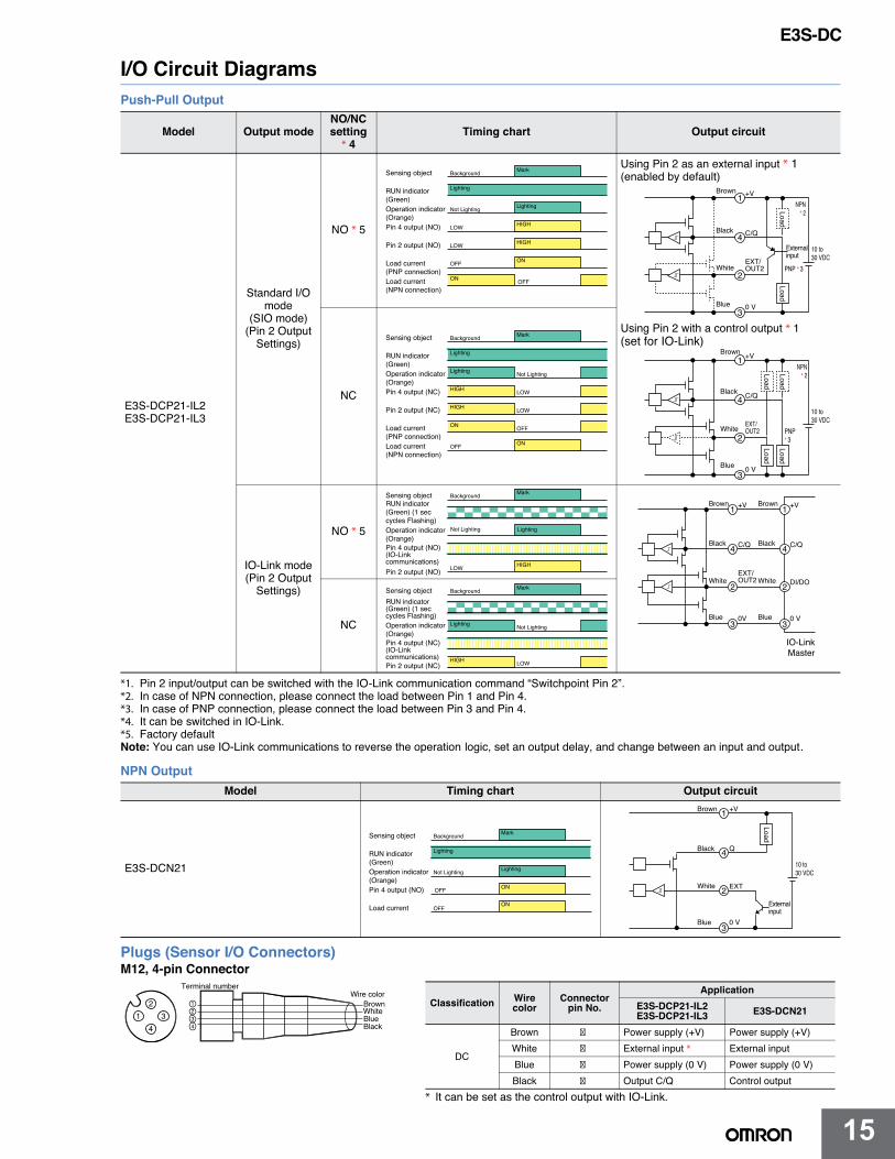
I/O Circuit DiagramsPush-Pull Output
*1. Pin 2 input/output can be switched with the IO-Link communication command “Switchpoint Pin 2”.*2. In case of NPN connection, please connect the load between Pin 1 and Pin 4.*3. In case of PNP connection, please connect the load between Pin 3 and Pin 4.*4. It can be switched in IO-Link.*5. Factory defaultNote: You can use IO-Link communications to reverse the operation logic, set an output delay, and change between an input and output.
NPN Output
Plugs (Sensor I/O Connectors)M12, 4-pin Connector
Model Output modeNO/NC setting
* 4Timing chart Output circuit
E3S-DCP21-IL2E3S-DCP21-IL3
Standard I/O mode
(SIO mode) (Pin 2 Output
Settings)
NO * 5
NC
IO-Link mode (Pin 2 Output
Settings)
NO * 5
NC
Model Timing chart Output circuit
E3S-DCN21
Sensing object MarkBackground
RUN indicator(Green)
Lighting
Operation indicator(Orange)
LightingNot Lighting
Pin 4 output (NO) HIGHLOW
Pin 2 output (NO) HIGHLOW
Load current(PNP connection)
ONOFF
OFFLoad current(NPN connection)
ON
Brown
Black
Blue
Load
+V1
4
2
3
10 to30 VDC
PNP * 3
NPN* 2
C/Q
WhiteEXT/OUT2
0 V
Externalinput
Load
Brown
Black
Blue
Load
+V1
4
2
3
10 to30 VDC
PNP* 3
NPN* 2
C/Q
White EXT/OUT2
0 V
Load
LoadLoad
Using Pin 2 as an external input * 1(enabled by default)
Using Pin 2 with a control output * 1(set for IO-Link)Sensing object MarkBackground
RUN indicator(Green)
Lighting
Operation indicator(Orange)
Lighting Not Lighting
Pin 4 output (NC) HIGH LOW
Pin 2 output (NC) HIGH LOW
Load current(PNP connection)
ON OFF
OFFLoad current(NPN connection)
ON
Sensing object MarkBackground
Operation indicator(Orange)
Not Lighting Lighting
Pin 2 output (NO)HIGHLOW
RUN indicator(Green) (1 seccycles Flashing)
Pin 4 output (NO)(IO-Linkcommunications)
IO-LinkMaster
Brown
Black
Blue
+V1
4
2
3
C/Q
WhiteEXT/OUT2
0V
Brown
Black
Blue
+V1
4
2
3
C/Q
White DI/DO
0 V
Sensing object MarkBackground
Operation indicator(Orange)
Pin 2 output (NC)HIGH LOW
Lighting Not Lighting
RUN indicator(Green) (1 seccycles Flashing)
Pin 4 output (NC)(IO-Linkcommunications)
Sensing object MarkBackground
Operation indicator(Orange)
LightingNot Lighting
Load current ONOFF
RUN indicator(Green)
Lighting
Pin 4 output (NO) ONOFF
Brown
Black
Blue
+V1
4
2
3
10 to30 VDC
Q
White EXT
0 V
Externalinput
Load
2
41 3
1234
Brown
BlueWhite
Black
Terminal numberWire color
* It can be set as the control output with IO-Link.
Classification Wire color
Connector pin No.
ApplicationE3S-DCP21-IL2E3S-DCP21-IL3 E3S-DCN21
DC
Brown Power supply (+V) Power supply (+V)White External input * External inputBlue Power supply (0 V) Power supply (0 V)Black Output C/Q Control output
E3S-DC
16
E3S-DC
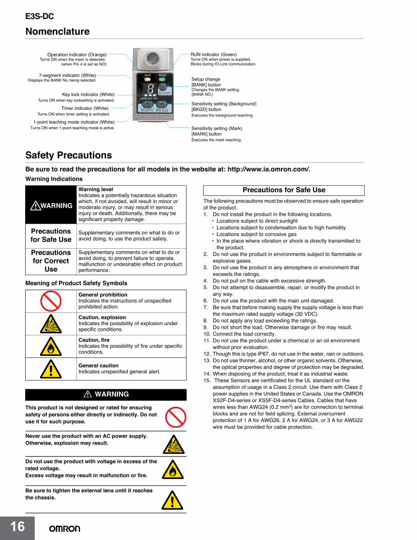
Nomenclature
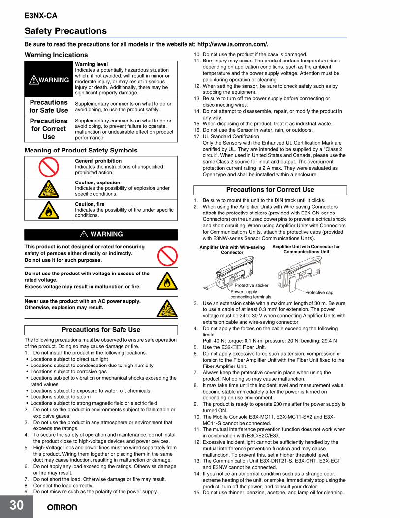
Safety PrecautionsBe sure to read the precautions for all models in the website at: http://www.ia.omron.com/.Warning Indications
Meaning of Product Safety Symbols
This product is not designed or rated for ensuring safety of persons either directly or indirectly. Do not use it for such purpose.
Never use the product with an AC power supply. Otherwise, explosion may result.
Do not use the product with voltage in excess of the rated voltage.Excess voltage may result in malfunction or fire.
Be sure to tighten the external lens until it reaches the chassis.
The following precautions must be observed to ensure safe operation of the product.1. Do not install the product in the following locations.
• Locations subject to direct sunlight• Locations subject to condensation due to high humidity• Locations subject to corrosive gas• In the place where vibration or shock is directly transmitted to
the product.2. Do not use the product in environments subject to flammable or
explosive gases.3. Do not use the product in any atmosphere or environment that
exceeds the ratings.4. Do not pull on the cable with excessive strength.5. Do not attempt to disassemble, repair, or modify the product in
any way.6. Do not use the product with the main unit damaged.7. Be sure that before making supply the supply voltage is less than
the maximum rated supply voltage (30 VDC).8. Do not apply any load exceeding the ratings.9. Do not short the load. Otherwise damage or fire may result.10. Connect the load correctly.11. Do not use the product under a chemical or an oil environment
without prior evaluation.12. Though this is type IP67, do not use in the water, rain or outdoors.13. Do not use thinner, alcohol, or other organic solvents. Otherwise,
the optical properties and degree of protection may be degraded.14. When disposing of the product, treat it as industrial waste.15. These Sensors are certificated for the UL standard on the
assumption of usage in a Class 2 circuit. Use them with Class 2 power supplies in the United States or Canada. Use the OMRON XS2F-D4-series or XS5F-D4-series Cables. Cables that have wires less than AWG24 (0.2 mm2) are for connection to terminal blocks and are not for field splicing. External overcurrent protection of 1 A for AWG26, 2 A for AWG24, or 3 A for AWG22 wire must be provided for cable protection.
Operation indicator (Orange)Turns ON when the mark is detected.
(when Pin 4 is set as NO)
RUN indicator (Green)Turns ON when power is supplied.Blinks during IO-Link communication.
Sensitivity setting (Background)[BKGD] buttonExecutes the background teaching.
7-segment indicator (White)Displays the BANK No. being selected.
Key lock indicator (White)Turns ON when key locksetting is activated.
Timer indicator (White)Turns ON when timer setting is activated.
1-point teaching mode indicator (White)Turns ON when 1-point teaching mode is active.
Setup change[BANK] buttonChanges the BANK setting.(BANK NO.)
Sensitivity setting (Mark)[MARK] buttonExecutes the mark teaching.
Warning levelIndicates a potentially hazardous situation which, if not avoided, will result in minor or moderate injury, or may result in serious injury or death. Additionally, there may be significant property damage.
Precautions for Safe Use
Supplementary comments on what to do or avoid doing, to use the product safely.
Precautions for Correct
Use
Supplementary comments on what to do or avoid doing, to prevent failure to operate, malfunction or undesirable effect on product performance.
General prohibitionIndicates the instructions of unspecified prohibited action.
Caution, explosionIndicates the possibility of explosion under specific conditions.
Caution, fireIndicates the possibility of fire under specific conditions.
General cautionIndicates unspecified general alert.
WARNING
WARNING
Precautions for Safe Use
E3S-DC
17
E3S-DC
1. Note that the water-resistant function is impaired if installing the Photoelectric Sensor by hitting it with a hammer and so on.
2. Be sure to tighten the external lens until it reaches the chassis.3. If the Sensor wiring is placed in the same conduits or ducts as
high-voltage or high-power lines, inductive noise may cause malfunction or damage. Wire the cables separately or use a shielded cable.
4. To extend a cable in the standard I/O mode, use a cable of 0.3 mm2 or more and keep the length 100 m or less. Keep the length 20 m or less if using the Sensor in the IO-Link mode.
5. Apply a screw tightening torque of 2.0 N·m or less.
6. If a commercial switching regulator is used, ground the FG (frame ground) terminal.
7. The Sensor will be able to detect objects 100 ms after the power supply is tuned ON. Start using the Sensor 100 ms or more after turning ON the power supply. If the load and the Sensor are connected to separate power supplies, be sure to turn ON the Sensor first.
8. Do not press the button with anything sharp such as a screwdriver because it might be damaged.
9. Output pulses may occur when the power supply is turned OFF. We recommend that you turn OFF the power supply to the load or load line first.
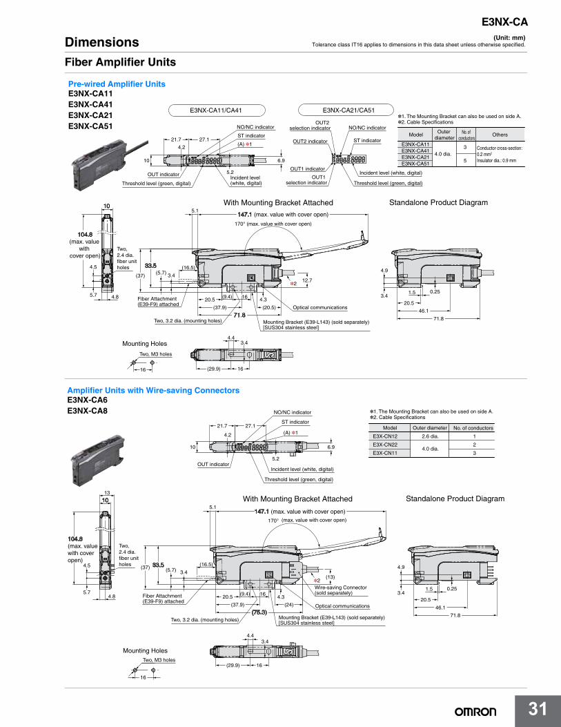
DimensionsSensors
Note: 1. Apply a screw tightening torque of 2.0 N·m or less.2. Be sure to tighten the external lens or cover until it reaches the chassis.
Precautions for Correct Use
(Unit: mm)Tolerance class IT16 applies to dimensions in this data sheet unless otherwise specified.
When Lens or Cover Is Replaced
Optical axis
M12 connector
Optical axis
Two, M5; Depth: 5.5
Four, M5; Depth: 5.5
17.7 dia. (lens diameter)
16.3
15
25
5215.2
3.2 16.8
3.2 28
80.4
53.7
0.5
0.2
24.8 dia. (Outer diameter)
5628
21
0.2
15
4.5
30
0.2
25
15
3.2 3.215
The optical axis can be changed byswapping the lens and cover.
The connector section can berevolved in a range of 90°.
Diffuse-reflective ModelsE3S-DCP21-IL2E3S-DCP21-IL3E3S-DCN21
E3S-DC

18
MEMO
E3S-DC
19
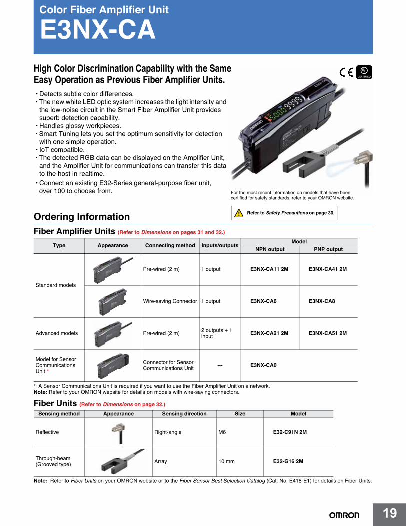
Color Fiber Amplifier Unit
E3NX-CA
Ordering InformationFiber Amplifier Units (Refer to Dimensions on pages 31 and 32.)
* A Sensor Communications Unit is required if you want to use the Fiber Amplifier Unit on a network.Note: Refer to your OMRON website for details on models with wire-saving connectors.
Fiber Units (Refer to Dimensions on page 32.)
Note: Refer to Fiber Units on your OMRON website or to the Fiber Sensor Best Selection Catalog (Cat. No. E418-E1) for details on Fiber Units.
Type Appearance Connecting method Inputs/outputsModel
NPN output PNP output
Standard models
Pre-wired (2 m) 1 output E3NX-CA11 2M E3NX-CA41 2M
Wire-saving Connector 1 output E3NX-CA6 E3NX-CA8
)m 2( deriw-erPsledom decnavdA 2 outputs + 1 input E3NX-CA21 2M E3NX-CA51 2M
Model for Sensor Communications Unit *
Connector for Sensor Communications Unit --- E3NX-CA0
For the most recent information on models that have been certified for safety standards, refer to your OMRON website.
Refer to Safety Precautions on page 30.
Sensing method Appearance Sensing direction Size Model
6Melgna-thgiRevitcelfeR E32-C91N 2M
Through-beam(Grooved type) Array 10 mm E32-G16 2M
High Color Discrimination Capability with the Same Easy Operation as Previous Fiber Amplifier Units.• Detects subtle color differences.• The new white LED optic system increases the light intensity and
the low-noise circuit in the Smart Fiber Amplifier Unit provides superb detection capability.
• Handles glossy workpieces.• Smart Tuning lets you set the optimum sensitivity for detection
with one simple operation.• IoT compatible.
• Connect an existing E32-Series general-purpose fiber unit, over 100 to choose from.
• The detected RGB data can be displayed on the Amplifier Unit, and the Amplifier Unit for communications can transfer this data to the host in realtime.

20
E3NX-CA
20
Accessories (Sold Separately)Wire-saving Connectors (Required for models for Wire-saving Connectors.) (Refer to Dimensions on page 33.)Connectors are not provided with the Fiber Amplifier Unit and must be ordered separately. *Protective stickers are provided.
Note: Models are also available with a 5-m cable. The model names have the suffix 5M. Ask your OMRON representative for delivery times.
Mounting Bracket (Refer to Dimensions on page 33.)A Mounting Bracket is not provided with the Fiber Amplifier Unit. It must be ordered separately as required.
DIN Tracks (Refer to Dimensions on page 34.)A DIN Track is not provided with the Fiber Amplifier Unit. It must be ordered separately as required.
Note: Refer to PFP- on your OMRON website for details.
End Plate (Refer to Dimensions on page 34.)Two End Plates are provided with the Sensor Communications Unit.End Plates are not provided with the Fiber Amplifier Unit. They must be ordered separately as required.
Note: Refer to PFP-M on your OMRON website for details.
Related ProductsSensor Communications Units
Note: Refer to your OMRON website for details.* The Distributed Sensor Unit can be connected to any of the Sensor Communications Units.
EtherCAT® is a registered trademark and patented technology, licensed by Beckhoff Automation GmbH, Germany.
Type Appearance Cable length No. of conductors Model Applicable Fiber Amplifier
Units
Master Connector
2 m
3 E3X-CN11
E3NX-CA6E3NX-CA8
Slave Connector 1 E3X-CN12
Appearance Model Quantity
E39-L143 1
Appearance Type Model Quantity
Shallow type, total length: 1 m PFP-100N
1Shallow type, total length: 0.5 m PFP-50N
Deep type, total length: 1 m PFP-100N2
Appearance Model Quantity
PFP-M 1
Type Appearance Model
Sensor CommunicationsUnit for EtherCAT E3NW-ECT
Distributed Sensor Unit * E3NW-DS
E3NX-CA
21
E3NX-CA
21
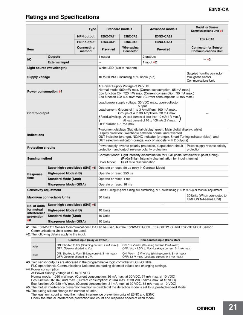
Ratings and Specifications
*1. The E3NW-ECT Sensor Communications Unit can be used, but the E3NW-CRT/CCL, E3X-DRT21-S, and E3X-CRT/ECT Sensor Communications Units cannot be used.
*2. The following details apply to the input.
*3. Two sensor outputs are allocated in the programmable logic controller (PLC) I/O table.PLC operation via Communications Unit enables reading detected values and changing settings.
*4.Power consumptionAt Power Supply Voltage of 10 to 30 VDCNormal mode: 1,080 mW max. (Current consumption: 36 mA max. at 30 VDC, 74 mA max. at 10 VDC)Eco function ON: 840 mW max. (Current consumption: 28 mA max. at 30 VDC, 50mA max. at 10 VDC)Eco function LO: 930 mW max. (Current consumption: 31 mA max. at 30 VDC, 55 mA max. at 10 VDC)
*5. The mutual interference prevention function is disabled if the detection mode is set to Super-high-speed Mode.*6. The tuning will not change the number of units.
The least unit count among the mutual interference prevention units of E3NX and E3NC. Check the mutual interference prevention unit count and response speed of each model.
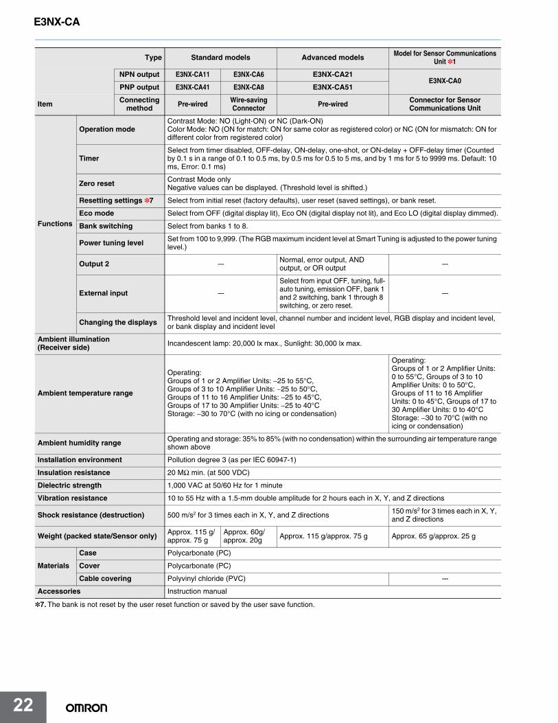
Type Standard models Advanced models Model for Sensor Communications Unit *1
NPN output E3NX-CA11 E3NX-CA6 E3NX-CA21E3NX-CA0
PNP output E3NX-CA41 E3NX-CA8 E3NX-CA51
Item Connecting method Pre-wired Wire-saving
Connector Pre-wired Connector for Sensor Communications Unit
I/OOutputs 1 output 2 outputs
--- *3External input --- 1 input *2
Light source (wavelength) White LED (420 to 700 nm)
Supply voltage 10 to 30 VDC, including 10% ripple (p-p)Supplied from the connector through the Sensor Communications Unit.
Power consumption *4
At Power Supply Voltage of 24 VDCNormal mode: 960 mW max. (Current consumption: 65 mA max.)Eco function ON: 720 mW max. (Current consumption: 30 mA max.)Eco function LO: 800 mW max. (Current consumption: 33 mA max.)
Control output
Load power supply voltage: 30 VDC max., open-collector output
Load current: Groups of 1 to 3 Amplifiers: 100 mA max., Groups of 4 to 30 Amplifiers: 20 mA max.
Residual voltage: At load current of less than 10 mA: 1 V max.At load current of 10 to 100 mA: 2 V max.
OFF current: 0.1 mA max.
---
Indications
7-segment displays (Sub digital display: green, Main digital display: white)Display direction: Switchable between normal and reversed.OUT indicator (orange), NO/NC indicator (orange), Smart Tuning indicator (blue), and OUT selection indicator (orange, only on models with 2 outputs)
Protection circuits Power supply reverse polarity protection, output short-circuit protection, and output reverse polarity protection
Power supply reverse polarity protection
Sensing methodContrast Mode: Light intensity discrimination for RGB (initial state/after 2-point tuning)
(R+G+B light intensity discrimination for 1-point tuning)Color Mode: RGB ratio discrimination
Response time
Super-high-speed Mode (SHS) *5 Operate or reset: 50 μs (only in Contrast Mode)
High-speed Mode (HS) Operate or reset: 250 μs
Standard Mode (Stnd) Operate or reset: 1 ms
Giga-power Mode (GIGA) Operate or reset: 16 ms
Sensitivity adjustment Smart Tuning (2-point tuning, full autotuning, or 1-point tuning (1% to 99%)) or manual adjustment
Maximum connectable Units 30 Units 30 Units (When connected to OMRON NJ-series Unit)
No. of Units for mutual interference prevention *6
Super-high-speed Mode (SHS) *5 ---
High-speed Mode (HS) 10 Units
Standard Mode (Stnd) 10 Units
Giga-power Mode (GIGA) 10 Units
Contact input (relay or switch) Non-contact input (transistor)
NPN ON: Shorted to 0 V (Sourcing current: 2 mA max.).OFF: Open or shorted to Vcc.
ON: 1.5 V max. (Sourcing current: 2 mA max.)OFF: Vcc - 1.5 V to Vcc (Leakage current: 0.1 mA max.)
PNP ON: Shorted to Vcc (Sinking current: 3 mA max.).OFF: Open or shorted to 0 V.
ON: Vcc - 1.5 V to Vcc (sinking current: 3 mA max.)OFF: 1.5 V max. (Leakage current: 0.1 mA max.)
( )
E3NX-CA
22
E3NX-CA
22
*7. The bank is not reset by the user reset function or saved by the user save function.
Type Standard models Advanced models Model for Sensor Communications Unit *1
NPN output E3NX-CA11 E3NX-CA6 E3NX-CA21E3NX-CA0
PNP output E3NX-CA41 E3NX-CA8 E3NX-CA51
Item Connecting method Pre-wired Wire-saving
Connector Pre-wired Connector for Sensor Communications Unit
Functions
Operation modeContrast Mode: NO (Light-ON) or NC (Dark-ON)Color Mode: NO (ON for match: ON for same color as registered color) or NC (ON for mismatch: ON for different color from registered color)
TimerSelect from timer disabled, OFF-delay, ON-delay, one-shot, or ON-delay + OFF-delay timer (Counted by 0.1 s in a range of 0.1 to 0.5 ms, by 0.5 ms for 0.5 to 5 ms, and by 1 ms for 5 to 9999 ms. Default: 10 ms, Error: 0.1 ms)
Zero reset Contrast Mode onlyNegative values can be displayed. (Threshold level is shifted.)
Resetting settings *7 Select from initial reset (factory defaults), user reset (saved settings), or bank reset.
Eco mode Select from OFF (digital display lit), Eco ON (digital display not lit), and Eco LO (digital display dimmed).
Bank switching Select from banks 1 to 8.
Power tuning level Set from 100 to 9,999. (The RGB maximum incident level at Smart Tuning is adjusted to the power tuning level.)
Output 2 --- Normal, error output, AND output, or OR output ---
External input ---
Select from input OFF, tuning, full-auto tuning, emission OFF, bank 1 and 2 switching, bank 1 through 8 switching, or zero reset.
---
Changing the displays Threshold level and incident level, channel number and incident level, RGB display and incident level, or bank display and incident level
Ambient illumination (Receiver side) Incandescent lamp: 20,000 lx max., Sunlight: 30,000 lx max.
Ambient temperature range
Operating: Groups of 1 or 2 Amplifier Units: −25 to 55°C, Groups of 3 to 10 Amplifier Units: −25 to 50°C, Groups of 11 to 16 Amplifier Units: −25 to 45°C, Groups of 17 to 30 Amplifier Units: −25 to 40°CStorage: −30 to 70°C (with no icing or condensation)
Operating: Groups of 1 or 2 Amplifier Units: 0 to 55°C, Groups of 3 to 10 Amplifier Units: 0 to 50°C, Groups of 11 to 16 Amplifier Units: 0 to 45°C, Groups of 17 to 30 Amplifier Units: 0 to 40°CStorage: −30 to 70°C (with no icing or condensation)
Ambient humidity range Operating and storage: 35% to 85% (with no condensation) within the surrounding air temperature range shown above
Installation environment Pollution degree 3 (as per IEC 60947-1)
Insulation resistance 20 MΩ min. (at 500 VDC)
Dielectric strength 1,000 VAC at 50/60 Hz for 1 minute
Vibration resistance 10 to 55 Hz with a 1.5-mm double amplitude for 2 hours each in X, Y, and Z directions
Shock resistance (destruction) 500 m/s2 for 3 times each in X, Y, and Z directions 150 m/s2 for 3 times each in X, Y, and Z directions
Weight (packed state/Sensor only) Approx. 115 g/approx. 75 g
Approx. 60g/approx. 20g Approx. 115 g/approx. 75 g Approx. 65 g/approx. 25 g
Materials
Case Polycarbonate (PC)
Cover Polycarbonate (PC)
Cable covering Polyvinyl chloride (PVC) ---
Accessories Instruction manual
E3NX-CA
23
E3NX-CA
23
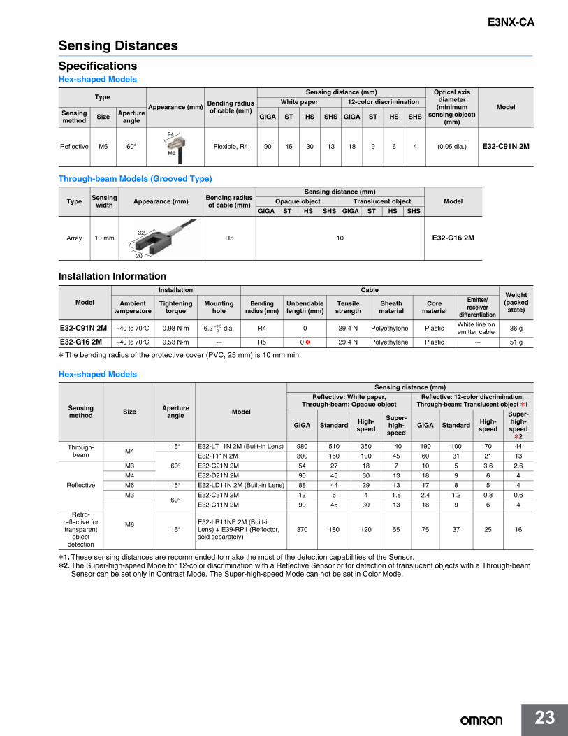
Sensing DistancesSpecificationsHex-shaped Models
Through-beam Models (Grooved Type)
Installation Information
* The bending radius of the protective cover (PVC, 25 mm) is 10 mm min.
Hex-shaped Models
*1. These sensing distances are recommended to make the most of the detection capabilities of the Sensor.*2. The Super-high-speed Mode for 12-color discrimination with a Reflective Sensor or for detection of translucent objects with a Through-beam
Sensor can be set only in Contrast Mode. The Super-high-speed Mode can not be set in Color Mode.
Type
Appearance (mm) Bending radius of cable (mm)
Sensing distance (mm) Optical axis diameter
(minimum sensing object)
(mm)
ModelWhite paper 12-color discrimination
Sensing method Size Aperture
angle GIGA ST HS SHS GIGA ST HS SHS
Reflective M6 60° Flexible, R4 90 45 30 13 18 9 6 4 (0.05 dia.) E32-C91N 2M
Type Sensing width Appearance (mm) Bending radius
of cable (mm)
Sensing distance (mm)
ModelOpaque object Translucent object
GIGA ST HS SHS GIGA ST HS SHS
Array 10 mm R5 10 E32-G16 2M
Model
Installation CableWeight (packed
state)Ambient
temperatureTightening
torqueMounting
holeBending
radius (mm)Unbendable length (mm)
Tensile strength
Sheathmaterial
Core material
Emitter/receiver
differentiation
E32-C91N 2M –40 to 70°C 0.98 N·m 6.2 dia. R4 0 29.4 N Polyethylene Plastic White line on emitter cable 36 g
E32-G16 2M –40 to 70°C 0.53 N·m --- R5 0 * 29.4 N Polyethylene Plastic --- 51 g
Sensing method Size Aperture
angle Model
Sensing distance (mm)
Reflective: White paper, Through-beam: Opaque object
Reflective: 12-color discrimination, Through-beam: Translucent object *1
GIGA Standard High-speed
Super-high-speed
GIGA Standard High-speed
Super-high-speed *2
Through-beam M4
15° E32-LT11N 2M (Built-in Lens) 980 510 350 140 190 100 70 44
60°E32-T11N 2M 300 150 100 45 60 31 21 13
Reflective
M3 E32-C21N 2M 54 27 18 7 10 5 3.6 2.6
M4 E32-D21N 2M 90 45 30 13 18 9 6 4
M6 15° E32-LD11N 2M (Built-in Lens) 88 44 29 13 17 8 5 4
M360°
E32-C31N 2M 12 6 4 1.8 2.4 1.2 0.8 0.6
M6
E32-C11N 2M 90 45 30 13 18 9 6 4
Retro-reflective for transparent
object detection
15°E32-LR11NP 2M (Built-in Lens) + E39-RP1 (Reflector, sold separately)
370 180 120 55 75 37 25 16
24
M6
32
20
7
+0.50
E3NX-CA
24
E3NX-CA
24
Threaded Models
Cylindrical Models
Flat Models
Sleeve Models
*1. These sensing distances are recommended to make the most of the detection capabilities of the Sensor.*2. The Super-high-speed Mode for 12-color discrimination with a Reflective Sensor or for detection of translucent objects with a Through-beam
Sensor can be set only in Contrast Mode. The Super-high-speed Mode can not be set in Color Mode.
Sensing method Size Aperture
angle Model
Sensing distance (mm)
Reflective: White paper, Through-beam: Opaque object
Reflective: 12-color discrimination, Through-beam: Translucent object *1
GIGA Standard High-speed
Super-high-speed
GIGA Standard High-speed
Super-high-speed *2
Through-beam M4
60° E32-T11R 2M 300 150 100 45 60 31 21 13
15°
E32-LT11 2M (Built-in Lens) 1,150 600 410 170 230 120 82 52
E32-LT11R 2M (Built-in Lens) 980 510 350 140 190 100 70 44
Reflective
M6E32-LD11 2M (Built-in Lens) 92 46 30 13 18 9 6 4
E32-LD11R 2M (Built-in Lens) 88 44 29 13 17 8 5 4
M3
60°E32-C31 2M 37 18 12 5 7 3.8 2.5 1.8
M6E32-D11R 2M 90 45 30 13 18 9 6 4
E32-CC200 2M 150 75 50 22 30 15 10 7
Sensing method
Sensing direction Size Model
Sensing distance (mm)
Reflective: White paper, Through-beam: Opaque object
Reflective: 12-color discrimination, Through-beam: Translucent object *1
GIGA Standard High-speed
Super-high-speed
GIGA Standard High-speed
Super-high-
speed *2
Through-beam
Top-view1.5 dia. E32-T22B 2M 110 64 37 16 22 12 7 5
3 dia.E32-T12R 2M 300 150 100 45 60 31 21 13
Side-view E32-T14LR 2M 190 100 68 29 38 20 13 8
Reflective Top-view
1.5 dia. E32-D22B 2M 17 8 6 2.4 3 2 1.2 0.7
3 dia.E32-D221B 2M 38 20 13 5 7 4 3 1.7
E32-D32L 2M 85 44 30 12 17 8 6 3.7
Sensing method
Sensing direction Model
Sensing distance (mm)
Reflective: White paper, Through-beam: Opaque object
Reflective: 12-color discrimination, Through-beam: Translucent object *1
GIGA Standard High-speed
Super-high-speed
GIGA Standard High-speed
Super-high-
speed *2
Through-beam
Flat-view E32-LT35Z 2M (Built-in Lens) 360 190 130 55 73 38 26 16
Top-view E32-T15XR 2M 300 150 100 45 60 31 21 13
Side-view E32-T15YR 2M 190 100 68 29 38 20 13 8
Flat-view E32-T15ZR 2M 190 100 68 29 38 20 13 8
Reflective
Top-view E32-D15XR 2M 90 45 30 13 18 9 6 4
Side-view E32-D15YR 2M 21 10 7 3.1 4.2 2.1 1.4 1
Flat-view E32-D15ZR 2M 21 10 7 3.1 4.2 2.1 1.4 1
Sensing method
Sensing direction Model
Sensing distance (mm)
Reflective: White paper, Through-beam: Opaque object
Reflective: 12-color discrimination, Through-beam: Translucent object *1
GIGA Standard High-speed
Super-high-speed
GIGA Standard High-speed
Super-high-
speed *2
Through-beam Top-view
E32-TC200BR 2M 300 150 100 45 60 31 21 13
Reflective E32-DC200BR 2M 90 45 30 13 18 9 6 4
E3NX-CA
25
E3NX-CA
25
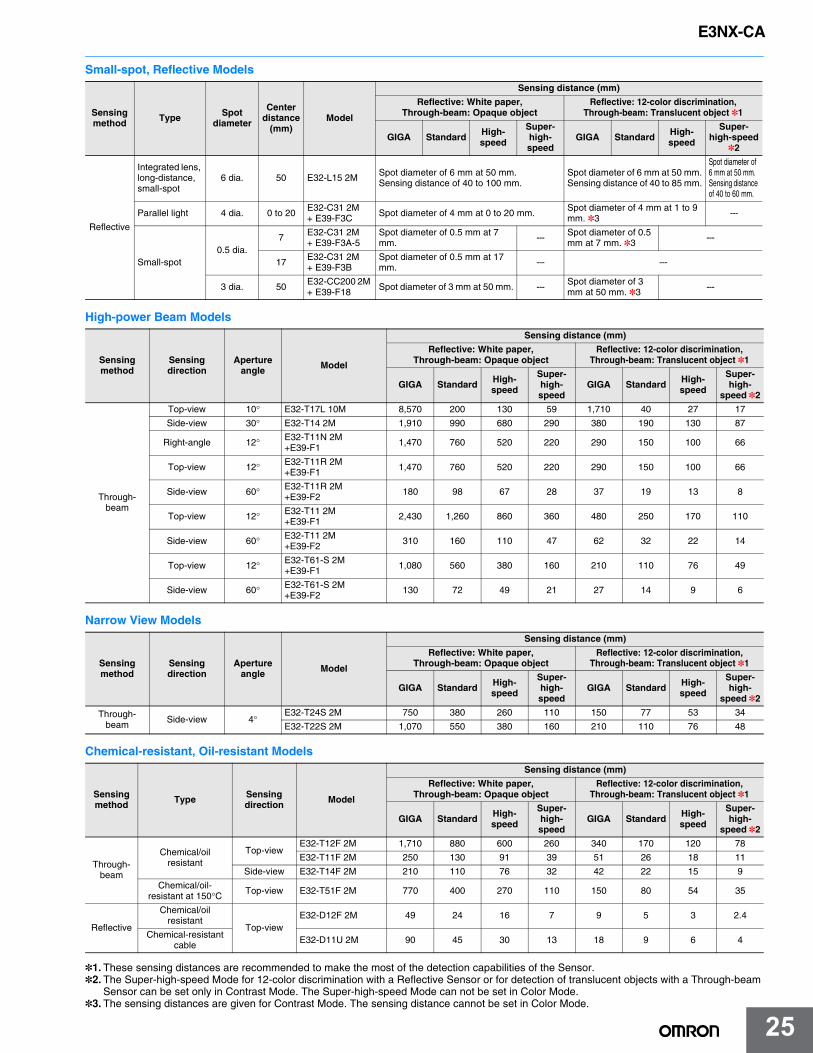
Small-spot, Reflective Models
High-power Beam Models
Narrow View Models
Chemical-resistant, Oil-resistant Models
*1. These sensing distances are recommended to make the most of the detection capabilities of the Sensor.*2. The Super-high-speed Mode for 12-color discrimination with a Reflective Sensor or for detection of translucent objects with a Through-beam
Sensor can be set only in Contrast Mode. The Super-high-speed Mode can not be set in Color Mode.*3. The sensing distances are given for Contrast Mode. The sensing distance cannot be set in Color Mode.
Sensing method Type Spot
diameter
Center distance
(mm)Model
Sensing distance (mm)
Reflective: White paper, Through-beam: Opaque object
Reflective: 12-color discrimination, Through-beam: Translucent object *1
GIGA Standard High-speed
Super-high-speed
GIGA Standard High-speed
Super-high-speed
*2
Reflective
Integrated lens, long-distance,small-spot
6 dia. 50 E32-L15 2M Spot diameter of 6 mm at 50 mm.Sensing distance of 40 to 100 mm.
Spot diameter of 6 mm at 50 mm.Sensing distance of 40 to 85 mm.
Spot diameter of 6 mm at 50 mm.Sensing distance of 40 to 60 mm.
Parallel light 4 dia. 0 to 20E32-C31 2M + E39-F3C
Spot diameter of 4 mm at 0 to 20 mm.Spot diameter of 4 mm at 1 to 9 mm. *3
---
Small-spot0.5 dia.
7 E32-C31 2M + E39-F3A-5
Spot diameter of 0.5 mm at 7 mm.
--- Spot diameter of 0.5 mm at 7 mm. *3
---
17E32-C31 2M + E39-F3B
Spot diameter of 0.5 mm at 17 mm. --- ---
3 dia. 50E32-CC200 2M + E39-F18
Spot diameter of 3 mm at 50 mm. ---Spot diameter of 3 mm at 50 mm. *3
---
Sensing method
Sensing direction
Aperture angle Model
Sensing distance (mm)
Reflective: White paper, Through-beam: Opaque object
Reflective: 12-color discrimination, Through-beam: Translucent object *1
GIGA Standard High-speed
Super-high-speed
GIGA Standard High-speed
Super-high-
speed *2
Through-beam
Top-view 10° E32-T17L 10M 8,570 200 130 59 1,710 40 27 17
Side-view 30° E32-T14 2M 1,910 990 680 290 380 190 130 87
Right-angle 12° E32-T11N 2M+E39-F1 1,470 760 520 220 290 150 100 66
Top-view 12° E32-T11R 2M+E39-F1 1,470 760 520 220 290 150 100 66
Side-view 60° E32-T11R 2M+E39-F2 180 98 67 28 37 19 13 8
Top-view 12° E32-T11 2M+E39-F1 2,430 1,260 860 360 480 250 170 110
Side-view 60° E32-T11 2M+E39-F2 310 160 110 47 62 32 22 14
Top-view 12° E32-T61-S 2M+E39-F1 1,080 560 380 160 210 110 76 49
Side-view 60° E32-T61-S 2M+E39-F2 130 72 49 21 27 14 9 6
Sensing method
Sensing direction
Aperture angle Model
Sensing distance (mm)
Reflective: White paper, Through-beam: Opaque object
Reflective: 12-color discrimination, Through-beam: Translucent object *1
GIGA Standard High-speed
Super-high-speed
GIGA Standard High-speed
Super-high-
speed *2
Through-beam Side-view 4°
E32-T24S 2M 750 380 260 110 150 77 53 34
E32-T22S 2M 1,070 550 380 160 210 110 76 48
Sensing method Type Sensing
direction Model
Sensing distance (mm)
Reflective: White paper, Through-beam: Opaque object
Reflective: 12-color discrimination, Through-beam: Translucent object *1
GIGA Standard High-speed
Super-high-speed
GIGA Standard High-speed
Super-high-
speed *2
Through-beam
Chemical/oil resistant
Top-viewE32-T12F 2M 1,710 880 600 260 340 170 120 78
E32-T11F 2M 250 130 91 39 51 26 18 11
Side-view E32-T14F 2M 210 110 76 32 42 22 15 9
Chemical/oil-resistant at 150°C Top-view E32-T51F 2M 770 400 270 110 150 80 54 35
Reflective
Chemical/oil resistant
Top-viewE32-D12F 2M 49 24 16 7 9 5 3 2.4
Chemical-resistant cable E32-D11U 2M 90 45 30 13 18 9 6 4
E3NX-CA
26
E3NX-CA
26
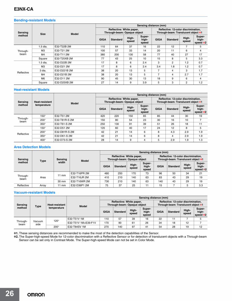
Bending-resistant Models
Heat-resistant Models
Area Detection Models
Vacuum-resistant Models
*1. These sensing distances are recommended to make the most of the detection capabilities of the Sensor.*2. The Super-high-speed Mode for 12-color discrimination with a Reflective Sensor or for detection of translucent objects with a Through-beam
Sensor can be set only in Contrast Mode. The Super-high-speed Mode can not be set in Color Mode.
Sensing method Size Model
Sensing distance (mm)
Reflective: White paper, Through-beam: Opaque object
Reflective: 12-color discrimination, Through-beam: Translucent object *1
GIGA Standard High-speed
Super-high-speed
GIGA Standard High-speed
Super-high-
speed *2
Through-beam
1.5 dia. E32-T22B 2M 110 64 37 16 22 12 7 5
M3 E32-T21 2M 100 57 33 14 20 11 6 4
M4 E32-T11 2M 380 200 130 58 77 40 27 17
Square E32-T25XB 2M 77 43 25 10 15 8 5 3.3
Reflective
1.5 dia. E32-D22B 2M 17 8 6 2.4 3 2 1.2 0.7
M3 E32-D21 2M 17 8 6 2.4 3.4 1.8 1.2 0.7
3 dia. E32-D221B 2M 38 20 13 5 7 4 3 1.7
M4 E32-D21B 2M 38 20 13 5 7 4 2.7 1.7
M6 E32-D11 2M 90 45 30 13 18 9 6 4
Square E32-D25XB 2M 27 14 9 3.9 5 3 2 1.2
Sensing method
Heat-resistant temperature Model
Sensing distance (mm)
Reflective: White paper, Through-beam: Opaque object
Reflective: 12-color discrimination, Through-beam: Translucent object *1
GIGA Standard High-speed
Super-high-speed
GIGA Standard High-speed
Super-high-
speed *2
Through-beam
150° E32-T51 2M 420 220 150 65 85 44 30 19
200° E32-T81R-S 2M 150 80 54 23 30 16 10 7
350° E32-T61-S 2M 250 130 91 39 51 26 18 11
Reflective
150° E32-D51 2M 120 60 40 17 24 12 8 5
200° E32-D81R-S 2M 42 21 14 6 8 4.3 2.9 1.9
350° E32-D61-S 2M 42 21 14 6 8 4 2.9 1.9
400° E32-D73-S 2M 28 14 9 4 5 2.9 1.9 1.3
Sensing method Type Sensing
width Model
Sensing distance (mm)
Reflective: White paper, Through-beam: Opaque object
Reflective: 12-color discrimination, Through-beam: Translucent object *1
GIGA Standard High-speed
Super-high-speed
GIGA Standard High-speed
Super-high-
speed *2
Through-beam Area
11 mmE32-T16PR 2M 480 250 170 73 96 50 34 21
E32-T16JR 2M 410 210 140 63 83 43 29 19
30 mm E32-T16WR 2M 730 210 140 63 140 43 29 19
Reflective Array 11 mm E32-D36P1 2M 75 37 25 11 15 7 5 3.3
Sensing method Type Heat-resistant
temperature Model
Sensing distance (mm)
Reflective: White paper, Through-beam: Opaque object
Reflective: 12-color discrimination, Through-beam: Translucent object *1
GIGA Standard High-speed
Super-high-speed
GIGA Standard High-speed
Super-high-
speed *2
Through-beam
Vacuum side
120°E32-T51V 1M 110 57 39 16 22 11 7 5
E32-T51V 1M+E39-F1V 170 90 61 26 34 18 12 7
200° E32-T84SV 1M 270 140 97 41 54 28 19 12
E3NX-CA
27
E3NX-CA
27
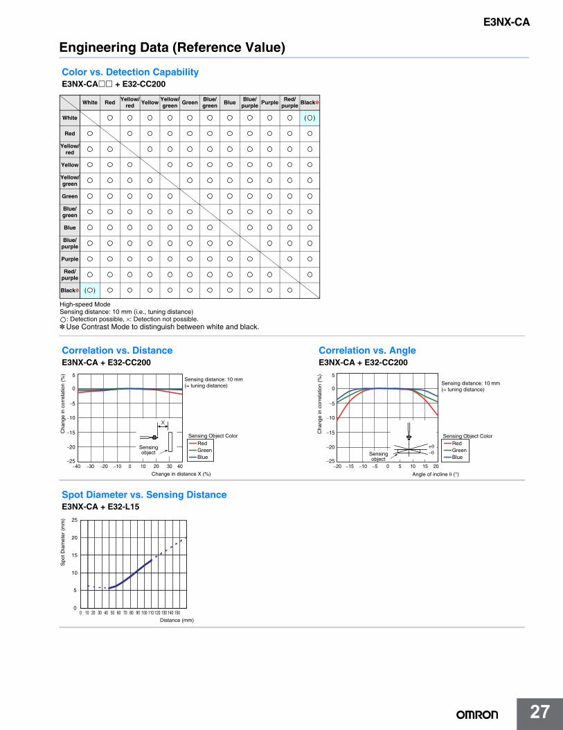
Engineering Data (Reference Value)
Color vs. Detection CapabilityE3NX-CA + E32-CC200
Correlation vs. DistanceE3NX-CA + E32-CC200
Correlation vs. AngleE3NX-CA + E32-CC200
Spot Diameter vs. Sensing DistanceE3NX-CA + E32-L15
High-speed ModeSensing distance: 10 mm (i.e., tuning distance)
: Detection possible, ×: Detection not possible.*Use Contrast Mode to distinguish between white and black.
White Red Yellow/red Yellow Yellow/
green Green Blue/green Blue Blue/
purple Purple Red/purple Black*
White ( )
Red
Yellow/red
Yellow
Yellow/green
Green
Blue/green
Blue
Blue/purple
Purple
Red/purple
Black* ( )
−25
−20
−15
−10
−5
0
5
Change in distance X (%)
X
Sensing distance: 10 mm (= tuning distance)
−40 −30 −20 −10 10 20 30 400
Blue
RedSensing Object Color
GreenSensing object
Cha
nge
in c
orre
latio
n (%
)
Angle of incline θ (°)
Sensing distance: 10 mm (= tuning distance)
Cha
nge
in c
orre
latio
n (%
)
−25
−20
−15
−10
−5
0
5
−20 −15 −10 −5 5 10 15 200
Blue
RedGreen
Sensing Object Color
+θ−θSensing
object
0
5
10
15
20
25
0 10 20 30 40 50 60 70 80 90 100 110 120 130 140 150
Distance (mm)
Spo
t Dia
met
er (
mm
)
E3NX-CA
28
E3NX-CA
28
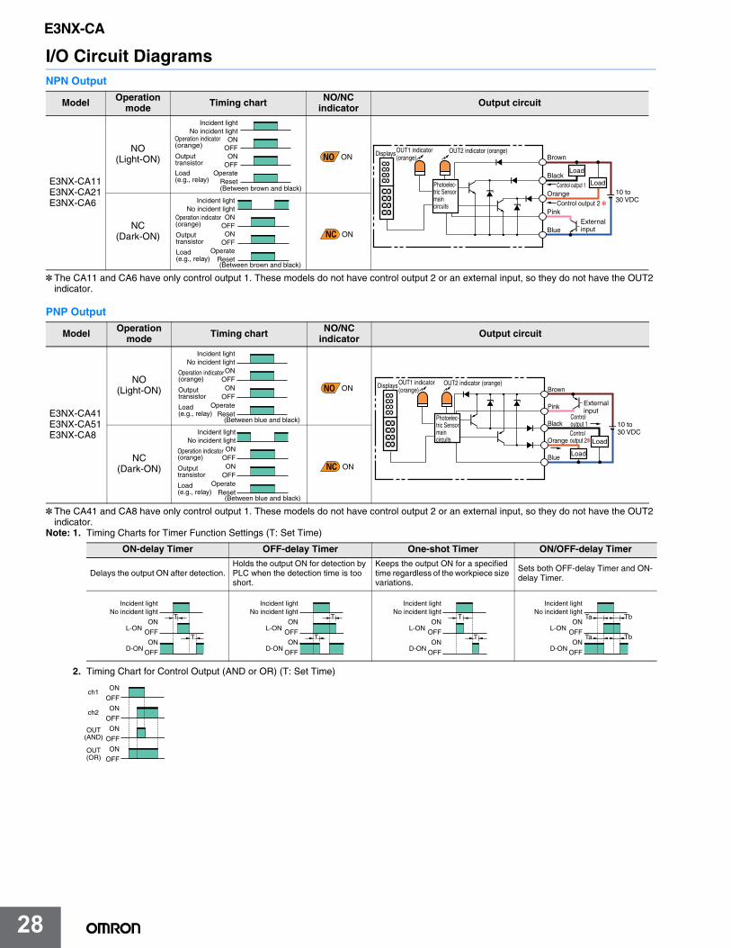
I/O Circuit DiagramsNPN Output
* The CA11 and CA6 have only control output 1. These models do not have control output 2 or an external input, so they do not have the OUT2 indicator.
PNP Output
* The CA41 and CA8 have only control output 1. These models do not have control output 2 or an external input, so they do not have the OUT2 indicator.
Note: 1. Timing Charts for Timer Function Settings (T: Set Time)
2. Timing Chart for Control Output (AND or OR) (T: Set Time)
Model Operation mode Timing chart NO/NC
indicator Output circuit
E3NX-CA11E3NX-CA21E3NX-CA6
NO (Light-ON)
NC (Dark-ON)
Model Operation mode Timing chart NO/NC
indicator Output circuit
E3NX-CA41E3NX-CA51E3NX-CA8
NO (Light-ON)
NC (Dark-ON)
ON-delay Timer OFF-delay Timer One-shot Timer ON/OFF-delay Timer
Delays the output ON after detection.Holds the output ON for detection by PLC when the detection time is too short.
Keeps the output ON for a specified time regardless of the workpiece size variations.
Sets both OFF-delay Timer and ON-delay Timer.
Incident lightNo incident light
ONOFFON
OFFOperate
Reset
Operation indicator (orange)
(Between brown and black)
Load (e.g., relay)
Outputtransistor
ON
Control output 1
Control output 2 *
Load
Load
OUT2 indicator (orange)Brown
Black
External input
Orange
Blue
Pink
10 to 30 VDC
OUT1 indicator (orange)
Displays
Photoelec-tric Sensor main circuits
Incident lightNo incident light
ONOFFON
OFFOperate
Reset
Operation indicator (orange)
(Between brown and black)
Load (e.g., relay)
Outputtransistor
ON
Incident lightNo incident light
ONOFFON
OFFOperate
Reset
Operation indicator (orange)
(Between blue and black)
Output transistor
Load (e.g., relay)
ON
Load
Load
OUT2 indicator (orange)
Control output 2*
Control output 1
Brown
Black
Pink
Orange
Blue
10 to 30 VDC
OUT1 indicator (orange)
Displays
External input
Photoelec-tric Sensor main circuits
Incident lightNo incident light
ONOFFON
OFFOperate
Reset
Operation indicator (orange)
(Between blue and black)
Output transistor
Load (e.g., relay)
ON
Incident lightNo incident light
ON
OFF
ON
OFF
L-ON
D-ON
T
T
Incident lightNo incident light
ON
OFF
ON
OFF
L-ON
D-ON
T
T
Incident lightNo incident light
ON
OFF
ON
OFF
L-ON
D-ON
T
T
Incident lightNo incident light
ON
OFF
ON
OFF
L-ON
D-ON
TbTa
TbTa
ch1
ch2
ON
OFF
ON
OFF
ON
OFF
ON
OFFOUT(OR)
OUT(AND)
E3NX-CA
29
E3NX-CA
29
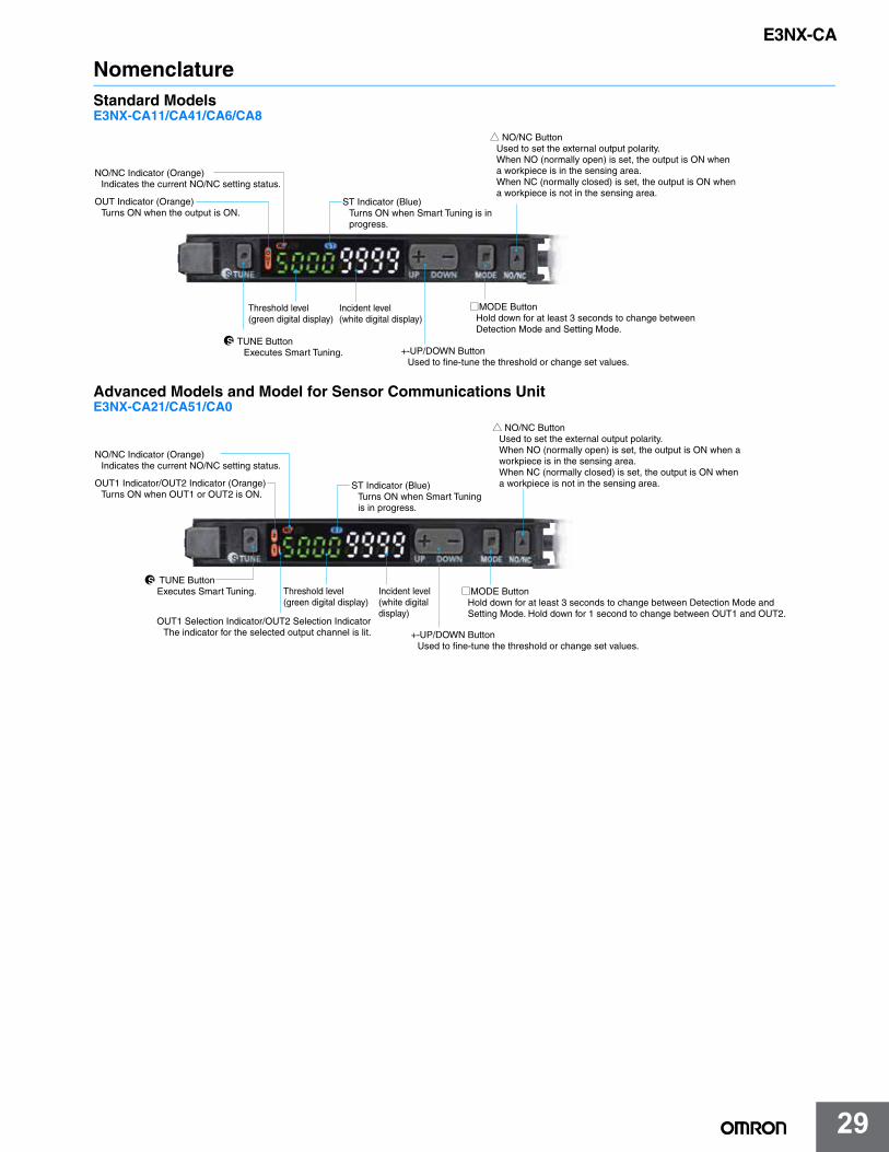
NomenclatureStandard ModelsE3NX-CA11/CA41/CA6/CA8
Advanced Models and Model for Sensor Communications UnitE3NX-CA21/CA51/CA0
NO/NC Indicator (Orange)Indicates the current NO/NC setting status.
OUT Indicator (Orange)Turns ON when the output is ON.
Threshold level(green digital display)
Incident level(white digital display)
+-UP/DOWN ButtonUsed to fine-tune the threshold or change set values.
TUNE ButtonExecutes Smart Tuning.
ST Indicator (Blue)Turns ON when Smart Tuning is in progress.
MODE ButtonHold down for at least 3 seconds to change between Detection Mode and Setting Mode.
NO/NC ButtonUsed to set the external output polarity.When NO (normally open) is set, the output is ON when a workpiece is in the sensing area.When NC (normally closed) is set, the output is ON when a workpiece is not in the sensing area.
OUT1 Selection Indicator/OUT2 Selection IndicatorThe indicator for the selected output channel is lit.
ST Indicator (Blue)Turns ON when Smart Tuning is in progress.
Threshold level(green digital display)
Incident level(white digital display)
+-UP/DOWN ButtonUsed to fine-tune the threshold or change set values.
TUNE ButtonExecutes Smart Tuning.
NO/NC Indicator (Orange)Indicates the current NO/NC setting status.
OUT1 Indicator/OUT2 Indicator (Orange)Turns ON when OUT1 or OUT2 is ON.
MODE ButtonHold down for at least 3 seconds to change between Detection Mode and Setting Mode. Hold down for 1 second to change between OUT1 and OUT2.
NO/NC ButtonUsed to set the external output polarity.When NO (normally open) is set, the output is ON when a workpiece is in the sensing area.When NC (normally closed) is set, the output is ON when a workpiece is not in the sensing area.
E3NX-CA
30
E3NX-CA
30
Safety PrecautionsBe sure to read the precautions for all models in the website at: http://www.ia.omron.com/.
Warning Indications
Meaning of Product Safety Symbols
This product is not designed or rated for ensuring safety of persons either directly or indirectly.Do not use it for such purposes.
Do not use the product with voltage in excess of the rated voltage.Excess voltage may result in malfunction or fire.
Never use the product with an AC power supply.Otherwise, explosion may result.
The following precautions must be observed to ensure safe operation of the product. Doing so may cause damage or fire.1. Do not install the product in the following locations.• Locations subject to direct sunlight• Locations subject to condensation due to high humidity• Locations subject to corrosive gas• Locations subject to vibration or mechanical shocks exceeding the
rated values• Locations subject to exposure to water, oil, chemicals• Locations subject to steam• Locations subject to strong magnetic field or electric field
2. Do not use the product in environments subject to flammable or explosive gases.
3. Do not use the product in any atmosphere or environment that exceeds the ratings.
4. To secure the safety of operation and maintenance, do not install the product close to high-voltage devices and power devices.
5. High-Voltage lines and power lines must be wired separately from this product. Wiring them together or placing them in the same duct may cause induction, resulting in malfunction or damage.
6. Do not apply any load exceeding the ratings. Otherwise damage or fire may result.
7. Do not short the load. Otherwise damage or fire may result.8. Connect the load correctly.9. Do not miswire such as the polarity of the power supply.
10. Do not use the product if the case is damaged.11. Burn injury may occur. The product surface temperature rises
depending on application conditions, such as the ambient temperature and the power supply voltage. Attention must be paid during operation or cleaning.
12. When setting the sensor, be sure to check safety such as by stopping the equipment.
13. Be sure to turn off the power supply before connecting or disconnecting wires.
14. Do not attempt to disassemble, repair, or modify the product in any way.
15. When disposing of the product, treat it as industrial waste.16. Do not use the Sensor in water, rain, or outdoors.17. UL Standard Certification
Only the Sensors with the Enhanced UL Certification Mark are certified by UL. They are intended to be supplied by a "Class 2 circuit". When used in United States and Canada, please use the same Class 2 source for input and output. The overcurrent protection current rating is 2 A max. They were evaluated as Open type and shall be installed within a enclosure.
1. Be sure to mount the unit to the DIN track until it clicks.2. When using the Amplifier Units with Wire-saving Connectors,
attach the protective stickers (provided with E3X-CN-series Connectors) on the unused power pins to prevent electrical shock and short circuiting. When using Amplifier Units with Connectors for Communications Units, attach the protective caps (provided with E3NW-series Sensor Communications Units).
3. Use an extension cable with a maximum length of 30 m. Be sure to use a cable of at least 0.3 mm2 for extension. The power voltage must be 24 to 30 V when connecting Amplifier Units with extension cable and wire-saving connector.
4. Do not apply the forces on the cable exceeding the following limits:Pull: 40 N; torque: 0.1 N·m; pressure: 20 N; bending: 29.4 N
5. Use the E32- Fiber Unit.6. Do not apply excessive force such as tension, compression or
torsion to the Fiber Amplifier Unit with the Fiber Unit fixed to the Fiber Amplifier Unit.
7. Always keep the protective cover in place when using the product. Not doing so may cause malfunction.
8. It may take time until the incident level and measurement value become stable immediately after the power is turned on depending on use environment.
9. The product is ready to operate 200 ms after the power supply is turned ON.
10. The Mobile Console E3X-MC11, E3X-MC11-SV2 and E3X-MC11-S cannot be connected.
11. The mutual interference prevention function does not work when in combination with E3C/E2C/E3X.
12. Excessive incident light cannot be sufficiently handled by the mutual interference prevention function and may cause malfunction. To prevent this, set a higher threshold level.
13. The Communication Unit E3X-DRT21-S, E3X-CRT, E3X-ECT and E3NW cannot be connected.
14. If you notice an abnormal condition such as a strange odor, extreme heating of the unit, or smoke, immediately stop using the product, turn off the power, and consult your dealer.
15. Do not use thinner, benzine, acetone, and lamp oil for cleaning.
Warning levelIndicates a potentially hazardous situation which, if not avoided, will result in minor or moderate injury, or may result in serious injury or death. Additionally, there may be significant property damage.
Precautions for Safe Use
Supplementary comments on what to do or avoid doing, to use the product safely.
Precautions for Correct
Use
Supplementary comments on what to do or avoid doing, to prevent failure to operate, malfunction or undesirable effect on product performance.
General prohibitionIndicates the instructions of unspecified prohibited action.
Caution, explosionIndicates the possibility of explosion under specific conditions.
Caution, fireIndicates the possibility of fire under specific conditions.
WARNING
Precautions for Safe Use
WARNING
Precautions for Correct Use
Protective stickerPower supply connecting terminals
Protective cap
Amplifier Unit with Wire-saving Connector
Amplifier Unit with Connector for Communications Unit
E3NX-CA
31
E3NX-CA
31
DimensionsFiber Amplifier Units
(Unit: mm)Tolerance class IT16 applies to dimensions in this data sheet unless otherwise specified.
Two, M3 holes
E3NX-CA11/CA41 E3NX-CA21/CA51
104.8(max. value
with cover open)
10
5.7
4.5
Two,2.4 dia. fiber unit holes
16
Mounting Holes
Standalone Product DiagramWith Mounting Bracket Attached
*1. The Mounting Bracket can also be used on side A.*2. Cable Specifications
E3NX-CA11
Model
4.0 dia.3
Outer diameter
No. of conductors
Conductor cross-section: 0.2 mm2
Insulator dia.: 0.9 mm
Others
E3NX-CA41E3NX-CA21
5E3NX-CA51
OUT2 selection indicator
OUT2 indicator
OUT1 indicator
OUT1 selection indicator Threshold level (green, digital)
ST indicator
NO/NC indicator
Incident level (white, digital)
10 6.9
21.7 27.1
4.2
5.2
(A) *1
NO/NC indicator
ST indicator
Incident level (white, digital)Threshold level (green, digital)
OUT indicator
4.8
5.1
(5.7) 3.4
(16.5)
147.1 (max. value with cover open)
20.5 16
Two, 3.2 dia. (mounting holes)
(9.4)
(37.9)
71.8(20.5)
4.3
12.7
170° (max. value with cover open)
Optical communications
Mounting Bracket (E39-L143) (sold separately) [SUS304 stainless steel]
Fiber Attachment (E39-F9) attached
(37)
33.5
*2
0.25
46.1
20.5
1.5
71.8
3.4
4.9
16(29.9)
4.43.4
Pre-wired Amplifier UnitsE3NX-CA11E3NX-CA41E3NX-CA21E3NX-CA51
E3X-CN12
E3X-CN22
2.6 dia. 1
Model Outer diameter No. of conductors
E3X-CN114.0 dia.
2
3
Two,2.4 dia. fiber unit holes
Two, M3 holes
16
Standalone Product DiagramWith Mounting Bracket Attached
Mounting Holes
*1. The Mounting Bracket can also be used on side A.*2. Cable Specifications
5.1
(13)
(16.5)
20.5 16(9.4)
3.4(37) (5.7)
(37.9)
(75.3)(24)
4.3
170° (max. value with cover open)
33.5
Optical communications
Mounting Bracket (E39-L143) (sold separately) [SUS304 stainless steel]
Wire-saving Connector (sold separately)
10
5.7
4.5
4.8
13
10
21.7
4.2
5.2
6.9
27.1(A) *1
NO/NC indicator
ST indicator
Incident level (white, digital)
Threshold level (green, digital)
OUT indicator
16(29.9)
4.43.4
Fiber Attachment (E39-F9) attached
46.1
20.5
1.5
71.8
3.40.25
4.9
104.8(max. value with cover open)
147.1 (max. value with cover open)
Two, 3.2 dia. (mounting holes)
*2
Amplifier Units with Wire-saving ConnectorsE3NX-CA6E3NX-CA8
E3NX-CA

32
E3NX-CA
32
Fiber Units
Two,2.4 dia. fiber unit holes
Mounted to DIN Track Standalone Product Diagram5.1
(16.5)
20.5
3.4(37) (5.7)
(37.9)
90.8(39.3)
152° (max. value with cover open)
33.526 (29.9)
Optical communications
PPE-N DIN Track (Sold separately.)
Fiber Attachment (E39-F9) attached
Connector (E3NX-CN30)
10
5.7
4.5
4.8
11.5
13.8
10
21 27.8
4.2
5.2
6.9
NO/NC indicator
ST indicator
Incident level (white, digital)
Threshold level (green, digital)OUT1 selection indicator
OUT1 indicator
OUT2 indicator
OUT2 selection indicator
0.25
46.1
20.5
1.5
71.8
3.4
4.9
104.8(max. value with cover open)
140 (max. value with cover open)
Amplifier Unit with Connector for Sensor Communications UnitE3NX-CA0
Reflective ModelsE32-C91N
18 3
6
2.5 dia.
(45)
2,000 (standard length)
Hexagonal nut, Opposite side:10, Thickness: 2.4 (Nickel-plated brass)
Toothed washer (nickel-plated iron)
Sensing head, M6 × 0.75 (Nickel-plated brass)
(5.6)
9.75
9.75
9.75
1 dia. emitter fiber (PMMA)
Sixteen 0.265-dia. receiver fibers
Model display tube Optical fibers: Two, 2.2 dia.
Two, M3 holesModel display tube
Sensing head (ABS)Protective cover (PVC) Optical fiber: 2.2 dia.
Cross-section A-A
Sensing surface, Sixteen, 0.265 dia.
Two, 3.2 dia. Mounting Holes28.48.4
1012
20
(45)
12±0.1
32
AA
7
15.910
2,000 (standard length)
Through-beam Models (Grooved Type) E32-G16
E3NX-CA
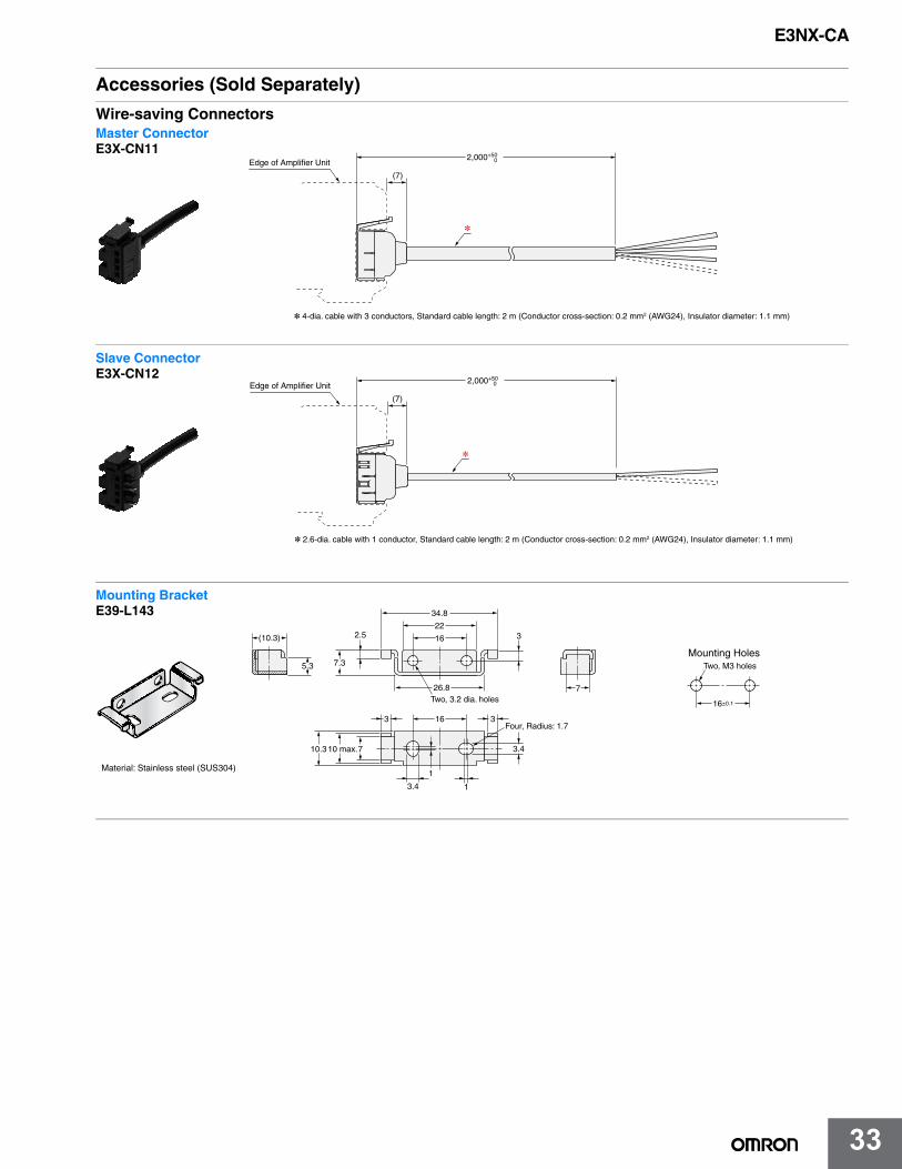
33
E3NX-CA
33
Accessories (Sold Separately)
Wire-saving Connectors
(7)
2,000+50 0
*
Edge of Amplifier Unit
* 4-dia. cable with 3 conductors, Standard cable length: 2 m (Conductor cross-section: 0.2 mm2 (AWG24), Insulator diameter: 1.1 mm)
Master ConnectorE3X-CN11
2,000+50 0
(7)
*
* 2.6-dia. cable with 1 conductor, Standard cable length: 2 m (Conductor cross-section: 0.2 mm2 (AWG24), Insulator diameter: 1.1 mm)
Edge of Amplifier Unit
Slave ConnectorE3X-CN12
Four, Radius: 1.7
7
3.4
1
3163
10 max.710.3
7.35.3
(10.3) 2.5
34.8
22
16
26.8
3
Two, 3.2 dia. holes
3.4
1
Two, M3 holes
16±0.1
Mounting Holes
Material: Stainless steel (SUS304)
Mounting BracketE39-L143
E3NX-CA
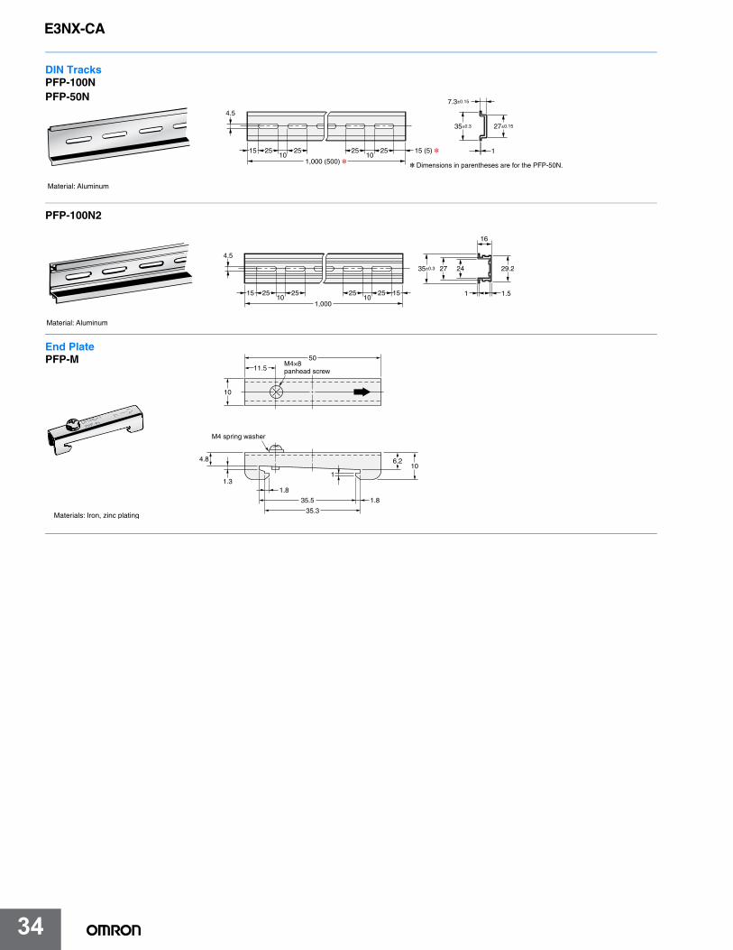
34
E3NX-CA
34
Material: Aluminum
4.5
15 25 2510 10
1,000 (500) *25 25 15 (5) *
35±0.3
7.3±0.15
27±0.15
1
* Dimensions in parentheses are for the PFP-50N.
DIN TracksPFP-100NPFP-50N
Material: Aluminum
4.5
15 25 2510 10
1,000
25 25 15 1 1.5
29.2242735±0.3
16
PFP-100N2
50
11.5
10
M4×8 panhead screw
M4 spring washer
4.8
1.31.8
1.8
1
6.210
35.5
35.3Materials: Iron, zinc plating
End PlatePFP-M
E3NX-CA
35
Terms and Conditions AgreementRead and understand this catalog.
Please read and understand this catalog before purchasing the products. Please consult your OMRON representative if you have any questions or comments.
Warranties.(a) Exclusive Warranty. Omron’s exclusive warranty is that the Products will be free from defects in materials and workmanship
for a period of twelve months from the date of sale by Omron (or such other period expressed in writing by Omron). Omron disclaims all other warranties, express or implied.
(b) Limitations. OMRON MAKES NO WARRANTY OR REPRESENTATION, EXPRESS OR IMPLIED, ABOUT NON-INFRINGEMENT, MERCHANTABILITY OR FITNESS FOR A PARTICULAR PURPOSE OF THE PRODUCTS. BUYER ACKNOWLEDGES THAT IT ALONE HAS DETERMINED THAT THE PRODUCTS WILL SUITABLY MEET THE REQUIREMENTS OF THEIR INTENDED USE.
Omron further disclaims all warranties and responsibility of any type for claims or expenses based on infringement by the Products or otherwise of any intellectual property right. (c) Buyer Remedy. Omron’s sole obligation hereunder shall be, at Omron’s election, to (i) replace (in the form originally shipped with Buyer responsible for labor charges for removal or replacement thereof) the non-complying Product, (ii) repair the non-complying Product, or (iii) repay or credit Buyer an amount equal to the purchase price of the non-complying Product; provided that in no event shall Omron be responsible for warranty, repair, indemnity or any other claims or expenses regarding the Products unless Omron’s analysis confirms that the Products were properly handled, stored, installed and maintained and not subject to contamination, abuse, misuse or inappropriate modification. Return of any Products by Buyer must be approved in writing by Omron before shipment. Omron Companies shall not be liable for the suitability or unsuitability or the results from the use of Products in combination with any electrical or electronic components, circuits, system assemblies or any other materials or substances or environments. Any advice, recommendations or information given orally or in writing, are not to be construed as an amendment or addition to the above warranty.
See http://www.omron.com/global/ or contact your Omron representative for published information.
Limitation on Liability; Etc.OMRON COMPANIES SHALL NOT BE LIABLE FOR SPECIAL, INDIRECT, INCIDENTAL, OR CONSEQUENTIAL DAMAGES, LOSS OF PROFITS OR PRODUCTION OR COMMERCIAL LOSS IN ANY WAY CONNECTED WITH THE PRODUCTS, WHETHER SUCH CLAIM IS BASED IN CONTRACT, WARRANTY, NEGLIGENCE OR STRICT LIABILITY.
Further, in no event shall liability of Omron Companies exceed the individual price of the Product on which liability is asserted.
Suitability of Use.Omron Companies shall not be responsible for conformity with any standards, codes or regulations which apply to the combination of the Product in the Buyer’s application or use of the Product. At Buyer’s request, Omron will provide applicable third party certification documents identifying ratings and limitations of use which apply to the Product. This information by itself is not sufficient for a complete determination of the suitability of the Product in combination with the end product, machine, system, or other application or use. Buyer shall be solely responsible for determining appropriateness of the particular Product with respect to Buyer’s application, product or system. Buyer shall take application responsibility in all cases.
NEVER USE THE PRODUCT FOR AN APPLICATION INVOLVING SERIOUS RISK TO LIFE OR PROPERTY OR IN LARGE QUANTITIES WITHOUT ENSURING THAT THE SYSTEM AS A WHOLE HAS BEEN DESIGNED TO ADDRESS THE RISKS, AND THAT THE OMRON PRODUCT(S) IS PROPERLY RATED AND INSTALLED FOR THE INTENDED USE WITHIN THE OVERALL EQUIPMENT OR SYSTEM.
Programmable Products.Omron Companies shall not be responsible for the user’s programming of a programmable Product, or any consequence thereof.
Performance Data.Data presented in Omron Company websites, catalogs and other materials is provided as a guide for the user in determining suitability and does not constitute a warranty. It may represent the result of Omron’s test conditions, and the user must correlate it to actual application requirements. Actual performance is subject to the Omron’s Warranty and Limitations of Liability.
Change in Specifications.Product specifications and accessories may be changed at any time based on improvements and other reasons. It is our practice to change part numbers when published ratings or features are changed, or when significant construction changes are made. However, some specifications of the Product may be changed without any notice. When in doubt, special part numbers may be assigned to fix or establish key specifications for your application. Please consult with your Omron’s representative at any time to confirm actual specifications of purchased Product.
Errors and Omissions.Information presented by Omron Companies has been checked and is believed to be accurate; however, no responsibility is assumed for clerical, typographical or proofreading errors or omissions.
E3NX-CA
E78I-E-01 Note: Specifications are subject to change. © 2016 Omron. All Rights Reserved. Printed in U.S.A.
Printed on recycled paper.
OMRON CANADA, INC. • HEAD OFFICEToronto, ON, Canada • 416.286.6465 • 866.986.6766 • www.omron247.com
OMRON ELECTRONICS DE MEXICO • HEAD OFFICEMéxico DF • 52.55.59.01.43.00 • 01-800-226-6766 • [email protected]
OMRON ELECTRONICS DE MEXICO • SALES OFFICEApodaca, N.L. • 52.81.11.56.99.20 • 01-800-226-6766 • [email protected]
OMRON ELETRÔNICA DO BRASIL LTDA • HEAD OFFICESão Paulo, SP, Brasil • 55.11.2101.6300 • www.omron.com.br
OMRON ARGENTINA • SALES OFFICECono Sur • 54.11.4783.5300
OMRON CHILE • SALES OFFICESantiago • 56.9.9917.3920
OTHER OMRON LATIN AMERICA SALES54.11.4783.5300
Authorized Distributor:
OMRON AUTOMATION AMERICAS HEADQUARTERS • Chicago, IL USA • 847.843.7900 • 800.556.6766 • www.omron247.com
OMRON EUROPE B.V. • Wegalaan 67-69, NL-2132 JD, Hoofddorp, The Netherlands. • +31 (0) 23 568 13 00 • www.industrial.omron.eu
Controllers & I/O • Machine Automation Controllers (MAC) • Motion Controllers • Programmable Logic Controllers (PLC) • Temperature Controllers • Remote I/O
Robotics • Industrial Robots • Mobile Robots
Operator Interfaces• Human Machine Interface (HMI)
Motion & Drives• Machine Automation Controllers (MAC) • Motion Controllers • Servo Systems • Frequency Inverters
Vision, Measurement & Identification• Vision Sensors & Systems • Measurement Sensors • Auto Identification Systems
Sensing• Photoelectric Sensors • Fiber-Optic Sensors • Proximity Sensors • Rotary Encoders • Ultrasonic Sensors
Safety • Safety Light Curtains • Safety Laser Scanners • Programmable Safety Systems • Safety Mats and Edges • Safety Door Switches • Emergency Stop Devices • Safety Switches & Operator Controls • Safety Monitoring/Force-guided Relays
Control Components • Power Supplies • Timers • Counters • Programmable Relays • Digital Panel Meters • Monitoring Products
Switches & Relays • Limit Switches • Pushbutton Switches • Electromechanical Relays • Solid State Relays
Software • Programming & Configuration • Runtime


![2012 Electronic Imaging - SPIE · Digital Imaging Sensors and Applications 8298 Sensors, Cameras, ... The single lens color/depth-unified sensor [1] can provide real time color and](https://img.pdfslide.us/doc/110x75/5f491c1b2b07a76cb9739ac6/2012-electronic-imaging-digital-imaging-sensors-and-applications-8298-sensors.jpg)


![Noise Reduction for CFA Image Sensors Exploiting …...Sensors 2009, 9 1693 sensors [6]. These are grayscale sensors covered by CFA (Color Filter Array) to enable color sensitivity,](https://img.pdfslide.us/doc/110x75/5f3e508525afa74ef5772a20/noise-reduction-for-cfa-image-sensors-exploiting-sensors-2009-9-1693-sensors.jpg)