Embed Size (px)
Citation preview
Collision with terrain involving Agusta AB206, VH-DPU 45 km NNW Gladstone Airport, Queensland, 17 March 2017
ATSB Transport Safety Report Aviation Occurrence Investigation AO-2017-033 Final – 5 September 2017
Released in accordance with section 25 of the Transport Safety Investigation Act 2003
Publishing information
Published by: Australian Transport Safety Bureau Postal address: PO Box 967, Civic Square ACT 2608 Office: 62 Northbourne Avenue Canberra, Australian Capital Territory 2601 Telephone: 1800 020 616, from overseas +61 2 6257 4150 (24 hours) Accident and incident notification: 1800 011 034 (24 hours) Facsimile: 02 6247 3117, from overseas +61 2 6247 3117 Email: [email protected] Internet: www.atsb.gov.au
© Commonwealth of Australia 2017
Ownership of intellectual property rights in this publication Unless otherwise noted, copyright (and any other intellectual property rights, if any) in this publication is owned by the Commonwealth of Australia.
Creative Commons licence With the exception of the Coat of Arms, ATSB logo, and photos and graphics in which a third party holds copyright, this publication is licensed under a Creative Commons Attribution 3.0 Australia licence.
Creative Commons Attribution 3.0 Australia Licence is a standard form license agreement that allows you to copy, distribute, transmit and adapt this publication provided that you attribute the work.
The ATSB’s preference is that you attribute this publication (and any material sourced from it) using the following wording: Source: Australian Transport Safety Bureau
Copyright in material obtained from other agencies, private individuals or organisations, belongs to those agencies, individuals or organisations. Where you want to use their material you will need to contact them directly. Addendum
Page Change Date
› 3 ‹
ATSB – AO-2017-033
Collision with terrain involving Agusta AB206, VH-DPU What happened On 17 March 2017, an Agusta AB206A helicopter, registered VH-DPU, departed Caboolture Airfield, for Curtis Island, Queensland, on a private flight. On board the helicopter were the pilot and one passenger.
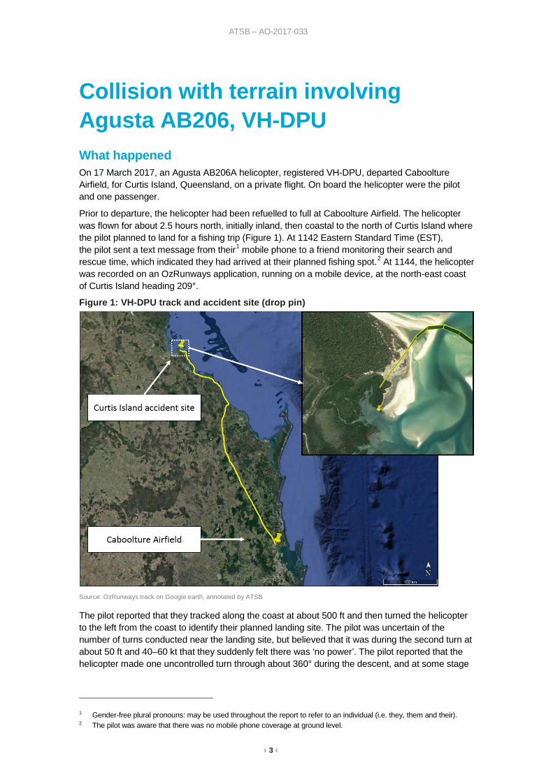
Prior to departure, the helicopter had been refuelled to full at Caboolture Airfield. The helicopter was flown for about 2.5 hours north, initially inland, then coastal to the north of Curtis Island where the pilot planned to land for a fishing trip (Figure 1). At 1142 Eastern Standard Time (EST), the pilot sent a text message from their1 mobile phone to a friend monitoring their search and rescue time, which indicated they had arrived at their planned fishing spot.2 At 1144, the helicopter was recorded on an OzRunways application, running on a mobile device, at the north-east coast of Curtis Island heading 209°.
Figure 1: VH-DPU track and accident site (drop pin)
Source: OzRunways track on Google earth, annotated by ATSB
The pilot reported that they tracked along the coast at about 500 ft and then turned the helicopter to the left from the coast to identify their planned landing site. The pilot was uncertain of the number of turns conducted near the landing site, but believed that it was during the second turn at about 50 ft and 40–60 kt that they suddenly felt there was ‘no power’. The pilot reported that the helicopter made one uncontrolled turn through about 360° during the descent, and at some stage
1 Gender-free plural pronouns: may be used throughout the report to refer to an individual (i.e. they, them and their). 2 The pilot was aware that there was no mobile phone coverage at ground level.
› 4 ‹
ATSB – AO-2017-033
they lowered the collective with the assumption the engine had failed.3 The main rotor blades appeared to be flapping4 violently to the point the pilot thought the blades were going to separate from the helicopter before impact with the water. The pilot and passenger reported that they did not see any caution lights or hear any audio alarms before or during the accident sequence.
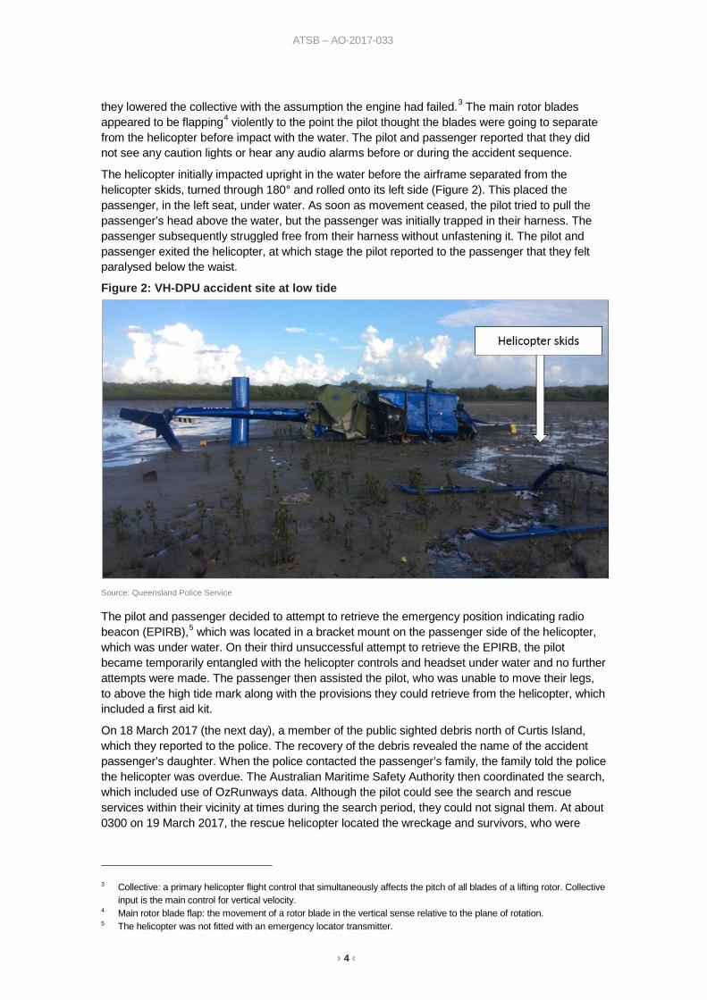
The helicopter initially impacted upright in the water before the airframe separated from the helicopter skids, turned through 180° and rolled onto its left side (Figure 2). This placed the passenger, in the left seat, under water. As soon as movement ceased, the pilot tried to pull the passenger’s head above the water, but the passenger was initially trapped in their harness. The passenger subsequently struggled free from their harness without unfastening it. The pilot and passenger exited the helicopter, at which stage the pilot reported to the passenger that they felt paralysed below the waist.
Figure 2: VH-DPU accident site at low tide
Source: Queensland Police Service
The pilot and passenger decided to attempt to retrieve the emergency position indicating radio beacon (EPIRB),5 which was located in a bracket mount on the passenger side of the helicopter, which was under water. On their third unsuccessful attempt to retrieve the EPIRB, the pilot became temporarily entangled with the helicopter controls and headset under water and no further attempts were made. The passenger then assisted the pilot, who was unable to move their legs, to above the high tide mark along with the provisions they could retrieve from the helicopter, which included a first aid kit.
On 18 March 2017 (the next day), a member of the public sighted debris north of Curtis Island, which they reported to the police. The recovery of the debris revealed the name of the accident passenger’s daughter. When the police contacted the passenger’s family, the family told the police the helicopter was overdue. The Australian Maritime Safety Authority then coordinated the search, which included use of OzRunways data. Although the pilot could see the search and rescue services within their vicinity at times during the search period, they could not signal them. At about 0300 on 19 March 2017, the rescue helicopter located the wreckage and survivors, who were
3 Collective: a primary helicopter flight control that simultaneously affects the pitch of all blades of a lifting rotor. Collective
input is the main control for vertical velocity. 4 Main rotor blade flap: the movement of a rotor blade in the vertical sense relative to the plane of rotation. 5 The helicopter was not fitted with an emergency locator transmitter.
› 5 ‹
ATSB – AO-2017-033
transferred to Rockhampton Hospital. The pilot and passenger were seriously injured and the helicopter was substantially damaged.
Fuel on board The helicopter was originally manufactured with a standard 288 L fuel tank and was subsequently modified with a fuel range extender device, which increased the fuel tank capacity to 344 L. The standard fuel refill port is not located at the top of the fuel tank. The range extender is an L-joint device fitted to the refill port, which raises the height of the refill port to increase the capacity of the fuel tank. It was reported that the helicopter was refuelled to full fuel (344 L) with the addition of 212 L on the morning of the accident by the pilot’s maintenance provider. The pilot did not visually inspect the fuel quantity, but noted the fuel gauge indicated full when power was applied to the helicopter.
The manufacturer calculated the helicopter would consume about 100 L per hour of fuel. If the helicopter had full fuel at departure, the manufacturer estimated that after 2.5 hours of flight there should have been about 94 L of fuel on board. This is greater than the quantity of fuel which would activate the low fuel level caution light, which is about 76 L. The pilot reported that the fuel gauge indicated about 25 gallons (95 L) when they conducted their pre-landing checks and the low fuel caution light did not illuminate during the flight. The passenger reported a strong smell of aviation fuel in the water immediately following the accident.
Examination of the wreckage The aviation loss surveyor appointed by the insurer recovered the helicopter wreckage from Curtis Island to Rockhampton for an initial examination. They found the fuel tank ruptured and fuel present in the fuel filter, which is located in the fuel line between the fuel tank and the engine. They followed the fuel line to the engine fuel control unit and found fuel present on both the inlet and outlet side of the unit. They inspected the engine inlet and outlet, and did not find any obvious damage. They noted one of the rotor blades had very little damage, which indicated to them that there was little rotational energy in the rotor blades at the time of impact.
The surveyor subsequently conducted further detailed inspections of components and parts. They found the drives for the fuel pump, fuel control unit and governor were intact. The engine and transmission chip detectors and filters for the fluid systems (fuel, oil and hydraulic) revealed no evidence of a mechanical failure.
ATSB review of photographic evidence The Queensland Police Service provided a considerable number of photographs of the wreckage to the ATSB. On review of the photographs, the ATSB could not identify any obvious mechanical fault with the helicopter that was not attributable to accident impact damage. The overhead circuit breaker panel had several tripped circuit breakers, including the warning lights, audio panel and instrument lights circuit breakers. However, it is possible for circuit breakers to trip as a result of impact forces.
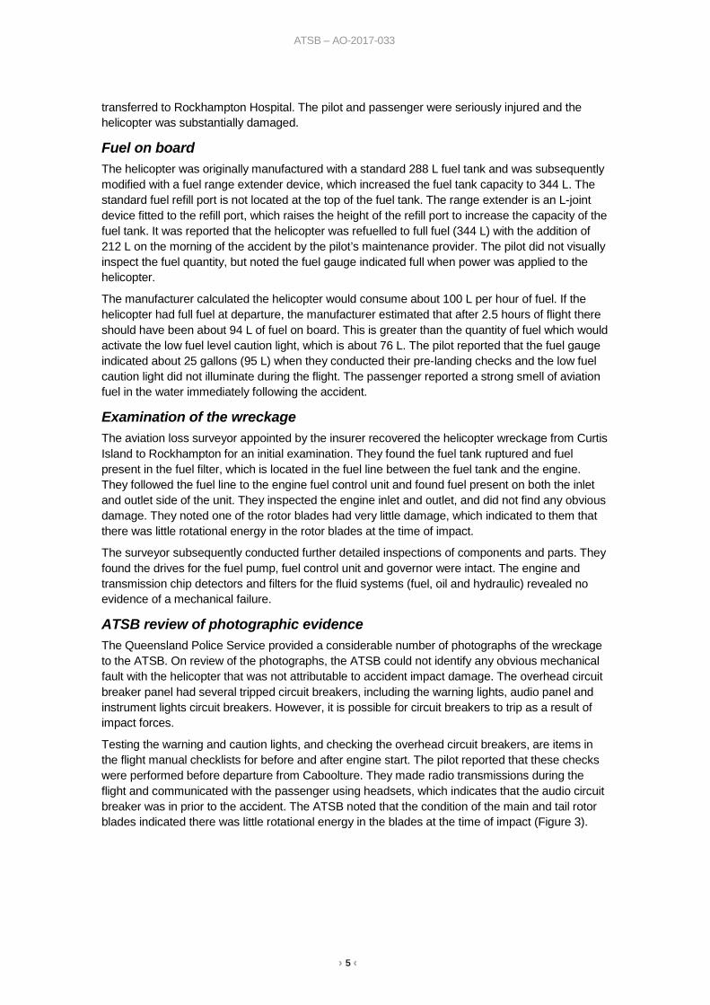
Testing the warning and caution lights, and checking the overhead circuit breakers, are items in the flight manual checklists for before and after engine start. The pilot reported that these checks were performed before departure from Caboolture. They made radio transmissions during the flight and communicated with the passenger using headsets, which indicates that the audio circuit breaker was in prior to the accident. The ATSB noted that the condition of the main and tail rotor blades indicated there was little rotational energy in the blades at the time of impact (Figure 3).
› 6 ‹
ATSB – AO-2017-033
Figure 3: VH-DPU main and tail rotor blades
Source: Queensland Police Service
Engine out warning The helicopter was fitted with an ‘engine out’ warning light and audio alarm (horn). The warning activates at 55 (+/- 3) per cent engine gas generator speed. Activation of the warning light is checked when the battery is switched on in the engine pre-start check. The pilot reported that this was checked serviceable before the accident flight in accordance with the checklist. The pilot and passenger reported that they did not observe any warning lights or hear any alarms during the accident sequence. The ATSB inspected the ‘engine out’ light bulb and found no evidence of stretching or ductile failure. Substantial impact force is required to damage a light bulb filament and a hot filament will sustain damage at a lower force than a cold filament. The absence of damage to the filament, by itself, is inconclusive.
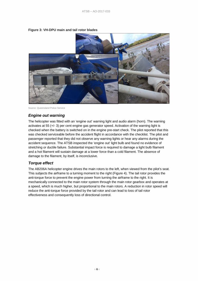
Torque effect The AB206A helicopter engine drives the main rotors to the left, when viewed from the pilot’s seat. This subjects the airframe to a turning moment to the right (Figure 4). The tail rotor provides the anti-torque force to prevent the engine power from turning the airframe to the right. It is mechanically connected to the main rotor system through the main rotor gearbox and operates at a speed, which is much higher, but proportional to the main rotors. A reduction in rotor speed will reduce the anti-torque force provided by the tail rotor and can lead to loss of tail rotor effectiveness and consequently loss of directional control.
› 7 ‹
ATSB – AO-2017-033
Figure 4: General effect of engine torque
Source: Bell Helicopter, annotated by ATSB (Agusta AB206A rotors turn in the same direction)
Rotor stalls During a powered descent, or a descent following an engine failure, the helicopter experiences a rate of descent airflow in opposition to the rotor induced airflow.6 This can increase the rotor blade’s angle of attack7 to the point that the root of the blades may stall.8 Decaying rotor speed is the initial indication. If the pilot does not respond to the early symptoms by lowering the collective, then the stalled region spreads outward towards the rotor tips. A complete rotor stall will lead to a loss of directional control, severe blade flapping and possible blade failure from high blade coning angles.9
Further information on rotor stall and how to recover from low rotor speed is available from the United States Federal Aviation Administration Helicopter flying handbook, chapter 11: Helicopter emergencies and hazards.
Pilot reaction to low rotor speed If a high collective setting is in use, then the rotor blades will have a high pitch setting with associated high rotor drag. In the absence of power, or with insufficient power, the high drag will reduce the speed of the rotors.
In 1999, the Flight Safety Foundation published the results of a United Kingdom Civil Aviation Authority (UK CAA) Simulator-based study of helicopter pilots’ reaction times.10
The research was conducted in response to three recommendations from fatal helicopter accidents in the UK in 1981, 1986 and 1992. The accidents were associated with low rotor speed at impact. 6 Induced airflow is airflow drawn in and accelerated by the rotor disc. 7 The angle of attack is the angular difference between the chord of the blade (straight line between the blade’s leading
edge and trailing edge) and the relative airflow. 8 Aerodynamic stall: occurs when airflow separates from the rotor blade’s upper surface and becomes turbulent. A stall
occurs at high angles of attack, typically 16˚ to 18˚, and results in reduced lift and increased drag. 9 Coning of main rotor blades: the upwards movement of the main rotor blades while they are rotating. This is usually in
response to an increase in aerodynamic force as a result of a control input from the pilot. It is more pronounced at high weights and/or low main rotor speed.
10 FSF Helicopter Safety (1999): Simulator-based study of emergencies yields insights into pilots’ reaction times. Vol. 25 No. 2.
› 8 ‹
ATSB – AO-2017-033
The UK CAA found that ‘pilots immediately detected failures involving variables within their focus of attention, but required more time to detect alerting cues outside their focus of attention.’ It also found that ‘auditory cues were probably the most significant alerting stimuli in each type of helicopter, and some differences in detection times correlated with the degree to which auditory cues were ‘attention getting’.’
Low rotor speed warning The AB206A helicopter flight manual emergency procedures section included the following details within the caution system:
Caution/warning light: ROTOR LOW RPM (audio & light) (if installed)
Fault and remedy: Rotor RPM is below normal. Reduce collective pitch and check that throttle is full open.
The 206A was manufactured by Agusta,11 in Europe, and by Bell Helicopter in North America and Canada. The accident helicopter was an Agusta AB206A, manufactured for the Austrian Army in 1969 and registered in Australia on 7 April 2011. The pilot was unsure if the helicopter was fitted with a low rotor speed warning system, but the former owner reported that it was not fitted. The manufacturer reported that at the time of the delivery of the helicopter from production, the low rotor speed warning system was not fitted to the AB206A helicopters. Bell Helicopter have published approved data to retrofit a low rotor speed warning system to some serial numbers of their 206A helicopters (service instruction 206-74), but there is currently no approved data to retrofit a low rotor speed warning system to the Agusta AB206A.
Certification specifications The accident helicopter was operating under the Civil Aviation Safety Authority type acceptance certificate for the AB206A, which referenced the European Aviation Safety Agency (EASA) issued type certificate data sheet for the certification specifications (CS). VH-DPU was manufactured in 1969 in Italy to the United States (US) Civil Aeronautics Board12 standard Civil Air Regulations Part 6 (CAR 6) Rotorcraft airworthiness: normal category, dated 20 December 1956.
Current EASA (CS-27) and US Federal Aviation Administration (27.33) certification specifications for ‘Main rotor speed and pitch limits’ include the following:
For each single engine helicopter…there must be a main rotor low speed warning.
In accordance with CS 27.33 (e) (1) and (3):
The warning must be furnished to the pilot in all flight conditions…when the speed of a main rotor approaches a value that can jeopardise safe flight, and, a visual device that requires the attention of the crew within the cockpit is not acceptable by itself.
The CAR 6 standard did not require the installation of a low rotor speed warning system, only instrument markings to indicate the limits beyond which operation is dangerous. Nevertheless, from the AB206B model, the low rotor speed warning system was factory installed as standard.
Previous accidents Low rotor speed The ATSB investigation of a forced landing involving a Robinson R44 helicopter (AO-2016-172) on 17 December 2016 indicated that the pilot was alerted to a low rotor speed condition by the associated warning horn. The pilot noted the rotor speed had reduced to 85 per cent at the time the warning directed their attention to the rotor speed. They were conscious of a potential rotor stall condition if they allowed the rotor speed to reduce below 80 per cent while they positioned the helicopter for an autorotation to a safe landing site.
11 Agusta are now Leonardo Helicopters 12 Precursor to the US Federal Aviation Administration
› 9 ‹
ATSB – AO-2017-033
Active noise reduction headsets The pilot of VH-DPU was wearing an active noise reduction (also known as noise cancelling) headset and was not alerted to any unusual noises before they experienced what they described as ‘no power.’ Several pilots involved in previous accidents have commented that the use of these headsets may have impeded their ability to hear aircraft warning devices or the early signs of an impending mechanical failure.
For further information see the following ATSB reports:
AO-2012-096 Ditching involving Robinson R44, VH-CYH
AO-2016-134 Wheels up landing involving Cessna 210, VH-UPN
AO-2017-041 Forced landing involving Robinson R44, VH-MQE
Emergency locator transmitters In 2013, the ATSB published a report on the effectiveness of emergency locator transmitters (ELTs) in aviation accidents (AR-2012-128). ELTs are radio beacons carried on aircraft so that in the event of an accident in a remote location the wreckage and survivors can be located quickly by search and rescue services. This increases the chances of survival for the occupants. The report included personal locator beacons (PLBs) and EPIRBs.
Airframe mounted ELTs are designed to automatically activate during a crash, by a g-force activated switch or, less commonly, by a water-activated switch. The report identified safety concerns regarding the operation of ELTs and found that they functioned as intended in about 40–60 per cent of accidents in which their activation was expected. The report indicated that carrying a PLB (or EPIRB) in place of, or as well as, an airframe mounted ELT will most likely only be beneficial to safety if it is carried on the person, rather than being fitted or stowed elsewhere in the aircraft.
Safety analysis Accident sequence The potential wind effect on the helicopter just prior to the accident sequence was not analysed due to the pilot’s uncertainty13 in the number of turns prior to and during the accident sequence and their report of light wind conditions leading up to the accident. The pilot reported that during the approach to land, there was suddenly ‘no power’ and that they experienced a sudden engine failure. However, the ATSB notes that the symptoms reported by the pilot were similar to the symptoms of a rotor stall.
If a helicopter is in an incipient rotor stall and the pilot either maintains or increases collective, the rotor stall will deepen. In this situation, the helicopter will not respond in the normal and expected manner, instead, rotor speed will decay and the rate of descent will increase. This response by the helicopter could be perceived by the pilot as a loss of power.
During the accident sequence, the airframe separated from the helicopter skids and turned 180°, which indicates that there was a turning moment (torque) on the airframe at touchdown. This is consistent with the pilot’s report that the helicopter rotated during the accident sequence. In the event of an engine failure, there will be no turning moment from the engine applied to the airframe. Any turning moment from the tail rotor is easily corrected and becomes negligible at low rotor speed. However, in a rotor stall the engine continues to apply torque to the airframe, which results in an uncommanded turn at low rotor speed.
The separation of the airframe from the landing skids, and final relative position of the airframe and landing skids, was consistent with low forward speed and engine torque combined with low 13 The pilot was seriously injured in the accident, which resulted in a 6 week delay before the ATSB were able to interview
them.
› 10 ‹
ATSB – AO-2017-033
rotor speed at impact. Therefore, the accident was probably the result of a rotor stall, but it was not determined how the helicopter entered the rotor stall. From the evidence available, fuel starvation or fuel exhaustion were considered unlikely.
Caution system The pilot checked the circuit breakers and tested the caution and warning lights before take-off. Therefore, the circuit breakers, which were found out post-accident, probably tripped as a result of the impact forces. The results of the analysis of the ‘engine out’ light bulb were inconclusive, but did not contradict the findings of the aviation loss surveyor, who found no evidence of pre-impact mechanical fault. Of note, the pilot was using an active noise reduction headset. Active noise reduction headsets could impair a pilot’s ability to hear a warning horn, such as the ‘engine out’ warning,14 which is not transmitted through the intercom system, or any subtle pitch changes in rotor speed or engine speed. However, the ATSB did not perform any tests to evaluate this effect.
Low rotor speed warning Previous research has found that auditory cues can reduce pilot detection time of a problem in an emergency. The current European and United States airworthiness standards for this category of helicopter require a main rotor low speed warning system, but this was not required for the accident helicopter, which was manufactured to 1956 standards. The pilot did not identify a low rotor speed condition before they experienced ‘no power’ and the helicopter was not fitted with a low rotor speed warning system.
The condition of the rotor blades post-impact indicated there was little rotational energy in the blades at the time of impact. The helicopter could lose rotor speed due to either an engine failure or rotor stall condition. In each case, other than an engine failure close to the ground,15 the pilot should lower the collective to maintain or recover rotor speed.
It is probable that the helicopter had entered an incipient rotor stall while the pilot’s attention was focused on positioning the helicopter for their intended landing site. In the absence of a low rotor speed warning this was initially undetected until the pilot suddenly experienced ‘no power’, at which stage there was insufficient height to recover. Therefore, the absence of a low rotor speed warning system increased the risk of a loss of control.
Emergency position indicating radio beacon The helicopter was carrying an emergency position indicating radio beacon (EPIRB), which must be manually activated. However, the pilot was unable to locate and retrieve the beacon from the wreckage in order to activate it after the accident. The pilot reported their arrival at their intended landing spot before the accident occurred, which, in combination with their inability to retrieve and activate the beacon, resulted in a considerable delay after the accident before search and rescue was activated.
The pilot and passenger were found by search and rescue services about 39 hours after the accident. Therefore, the absence of an automatically activated emergency locator transmitter (ELT) and the inability of the occupants to retrieve their EPIRB increased the risks associated with their post-accident survival.
Findings These findings should not be read as apportioning blame or liability to any particular organisation or individual.
14 The ‘engine out' warning horn is transmitted through a cabin speaker. 15 Close to the ground there is no time to enter autorotation and the pilot is only required to raise the collective, as
required, to minimise the rate of descent at touchdown.
› 11 ‹
ATSB – AO-2017-033
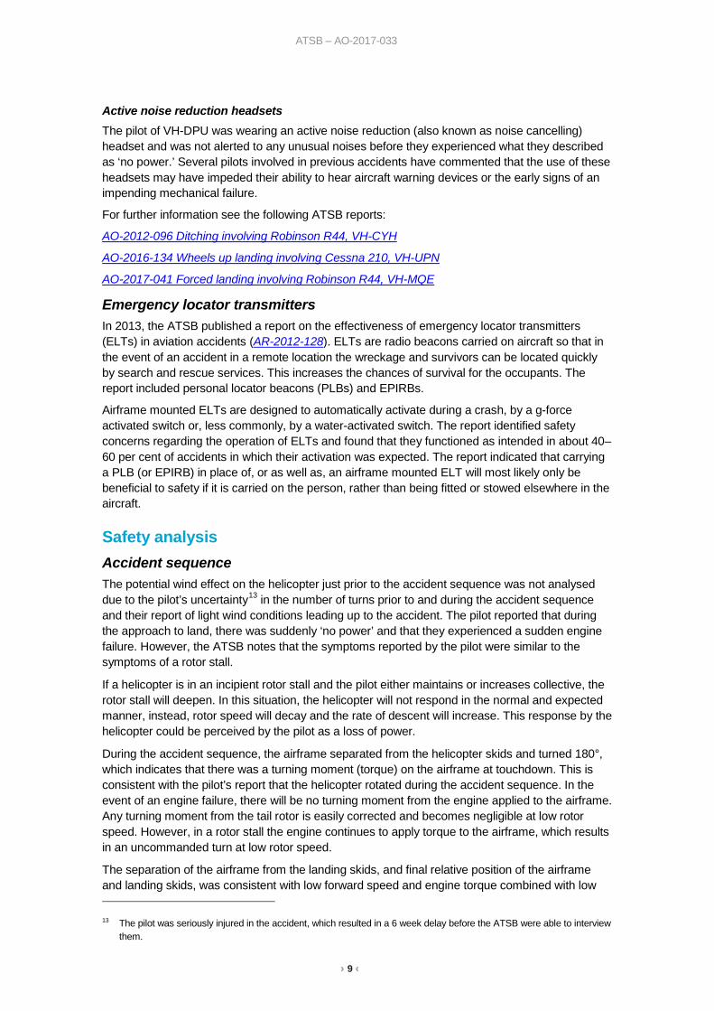
• It is probable the helicopter experienced a main rotor stall from a low height and low forward speed.
• The helicopter was not fitted with a low rotor speed warning system. A low rotor speed warning system was not a certification requirement for the helicopter at the time of manufacture and there is currently no approved data for the modification. The absence of a low rotor speed warning system increased the risk of the pilot losing control of the helicopter.
• The helicopter was carrying an emergency position indicating radio beacon which was inaccessible after the accident. This resulted in a considerable delay to the search and rescue.
• The pilot reported a sudden loss of power. However, examination of the wreckage by the aviation loss surveyor found no evidence of pre-impact mechanical fault. Fuel starvation or fuel exhaustion were considered unlikely.
Safety message The pilot reported that it was beneficial to have a first aid kit on board the helicopter, which they retrieved and used following the accident. However, they considered it necessary to carry the emergency position indicating radio beacon on the person, rather than fitted to the helicopter. They further noted that a high quality strobe light would have assisted them to signal their location once search and rescue services were in the vicinity.
The use of active noise reduction (noise cancelling) headsets has become prevalent in aviation. It is, however, important to always consider their compatibility with the aircraft warning systems. The Civil Aviation Safety Authority have published an airworthiness article (previously an airworthiness advisory circular) AAC 1-43 Noise isolating headsets, which highlights the potential benefits and risks associated with the use of these headsets.
General details Occurrence details
Date and time: 17 March 2017 – 1144 EST
Occurrence category: Accident
Primary occurrence type: Collision with terrain
Location: 45 km NNW Gladstone Airport, Queensland
Latitude: 23° 29.27’ S Longitude: 151° 04.33’ E
Aircraft details Manufacturer and model: Agusta, S.p.A, Costruzioni Aeronautiche AB 206A
Registration: VH-DPU
Serial number: 8130
Type of operation: Private
Persons on board: Crew – 1 Passengers – 1
Injuries: Crew – 1 (serious) Passengers – 1 (serious)
Aircraft damage: Substantial
› 1 ‹
ATSB – AO-2017-033
About the ATSB The Australian Transport Safety Bureau (ATSB) is an independent Commonwealth Government statutory agency. The ATSB is governed by a Commission and is entirely separate from transport regulators, policy makers and service providers. The ATSB's function is to improve safety and public confidence in the aviation, marine and rail modes of transport through excellence in: independent investigation of transport accidents and other safety occurrences; safety data recording, analysis and research; and fostering safety awareness, knowledge and action.
The ATSB is responsible for investigating accidents and other transport safety matters involving civil aviation, marine and rail operations in Australia that fall within Commonwealth jurisdiction, as well as participating in overseas investigations involving Australian registered aircraft and ships. A primary concern is the safety of commercial transport, with particular regard to operations involving the travelling public.
The ATSB performs its functions in accordance with the provisions of the Transport Safety Investigation Act 2003 and Regulations and, where applicable, relevant international agreements.
The object of a safety investigation is to identify and reduce safety-related risk. ATSB investigations determine and communicate the safety factors related to the transport safety matter being investigated.
It is not a function of the ATSB to apportion blame or determine liability. At the same time, an investigation report must include factual material of sufficient weight to support the analysis and findings. At all times the ATSB endeavours to balance the use of material that could imply adverse comment with the need to properly explain what happened, and why, in a fair and unbiased manner.
About this report Decisions regarding whether to conduct an investigation, and the scope of an investigation, are based on many factors, including the level of safety benefit likely to be obtained from an investigation. For this occurrence, a limited-scope, fact-gathering investigation was conducted in order to produce a short summary report, and allow for greater industry awareness of potential safety issues and possible safety actions.