Embed Size (px)
Citation preview

1 van 117
Collision between a passenger train and a man lift at Dalfsen
DUTCHSAFETY BOARD

The Hague, December 2016
The reports issued by the Dutch Safety Board are open to the public.
All reports are also available on the Safety Board’s website www.safetyboard.nl
Cover photo: Dutch Safety Board
Collision between a passenger train and a man lift at Dalfsen
2 van 117

Dutch Safety Board
When accidents or disasters happen, the Dutch Safety Board investigates how it was possible for them to occur, with the aim of learning lessons for the future and, ultimately, improving safety in the Netherlands. The Safety Board is independent and is free to decide which incidents to investigate. In particular, it focuses on situations in which people’s personal safety is dependent on third parties, such as the government or companies. In certain cases the Board is under an obligation to carry out an investigation. Its investigations do not address issues of blame or liability.
Dutch Safety BoardChairman: T.H.J. Joustra
E.R. MullerM.B.A. van Asselt
Secretary Director: C.A.J.F. Verheij
Visiting address: Anna van Saksenlaan 502593 HT The Hague The Netherlands
Postal address: PO Box 954042509 CK The Hague The Netherlands
Telephone: +31 (0)70 333 7000 Fax: +31 (0)70 333 7077
Website: www.safetyboard.nl
NB: This report is published in the Dutch and English languages. If there is a difference in interpretation between the Dutch and English versions, the Dutch text will prevail.
3 van 117
4 van 117
CONTENT
Summary and consideration ��������������������������������������������������������������������������������������� 6
List of abbreviations �������������������������������������������������������������������������������������������������������12
1 Introduction ���������������������������������������������������������������������������������������������������������131.1 Reasons for the investigation 141.2 Why an investigation by the Dutch Safety Board? 141.3 Investigation questions 151.4 Scope of the investigation 151.5 Investigative approach 15
2 The accident ���������������������������������������������������������������������������������������������������������172.1 The Het Lage Veld level crossing in Dalfsen 182.2 The man lift and the train 192.3 The circumstances and consequences of the collision 212.4 Findings 26
3 Crossing by the man lift���������������������������������������������������������������������������������������273.1 Introduction 283.2 Use of the man lift 283.3 Execution of the crossing 293.4 Underlying factors 303.5 Other accidents where more crossing time is required 353.6 Conclusions 37
4 Train crashworthiness ����������������������������������������������������������������������������������������� 384.1 Introduction 394.2 Crashworthiness requirements focus on the occupants 394.3 Collapse of the driver’s cab 414.4 Train driver escape options 434.5 Comparison with other accidents 454.6 Crashworthiness acceptance requirements 504.7 Monitoring of build quality 514.8 Conclusions 52
5 Level crossing safety ������������������������������������������������������������������������������������������ 535.1 Introduction 545.2 No action framework for clearance problems 545.3 Risk assessment of level crossings 555.4 Number of level crossings 585.5 Comparison with other countries 64

5 van 117
5.6 Conclusions 69
6 Conclusions ����������������������������������������������������������������������������������������������������������706.1 Relevant facts about the accident 716.2 Structural factors requiring improvement 72
7 Recommendations������������������������������������������������������������������������������������������������75
APPENDIX
Appendix A� Justification of the investigation ������������������������������������������������������� 79
Appendix B� Responses to the draft report ����������������������������������������������������������� 84
Appendix C� Technical findings ������������������������������������������������������������������������������� 85C.1 Reconstruction of the circumstances ................................................ 85C.2 Collapse of the driver’s cab .............................................................. 95
Appendix D� Collisions between passenger trains and heavy vehicles �����������������104
Appendix E� Accidents involving Stadler trains �����������������������������������������������������111E.1 Fatal accidents abroad involving Stadler trains ...............................111E.2 Previous level crossing collisions involving GTW trains in
the Netherlands ...............................................................................113
Appendix F� Level crossings with obstacle detection �������������������������������������������115

SUMMARY AND CONSIDERATION
On 23 February 2016, a passenger train travelling at high speed collided with a man lift crossing a level crossing in Dalfsen. The train driver was killed in the accident; the cab he was in was completely destroyed. Two of the other six people on the train suffered minor injuries. The man lift operator jumped out of his vehicle shortly before the collision, suffering minor injuries as a result. The train derailed and ended up on its side; the man lift was completely destroyed.
The accident gave the Dutch Safety Board cause to investigate whether lessons could be learnt for improving level crossing safety in general.
Summary
The investigation focused primarily on the man lift’s crossing manoeuvre, the crashworthiness of the train and the safety of the level crossing.
The man lift’s crossing manoeuvrePrior to the accident, the landscaping firm had used the man lift involved in the collision to uproot a tree on a plot of land close to the level crossing. An employee of the landscaping firm was driving the man lift, via the level crossing, to the start of the road where the rental company was to collect it with a truck. The level crossing was protected by automatic half barriers. These automatic half barriers had a normal warning time, but the time required for this man lift to cross was approximately three times longer. Those involved believed that the crossing was nevertheless possible, because they assumed that the period between two train passages would be at least ten minutes. One day earlier, when they had made the journey in the opposite direction, this had indeed been the case. However, the return journey took place at a different time of day, when the period was only approximately six minutes, in accordance with the timetable. The accident threat became clear to the man lift operator when he saw that a train was approaching during the crossing manoeuvre. However, avoiding the collision was by then no longer an option.
Train crashworthiness and train driver’s escape optionsThe fact that the train cab was destroyed was primarily due to the train’s high speed and to a lesser extent the large mass and the rigidity of the man lift and its low centre of gravity. The impact of the collision was four times higher than a train must be capable of withstanding according to the current standard for crashworthiness. Moreover, considerable forces were probably exerted on the front of the train again after it collided with the man lift, as a result of crashing into an overhead lines pole and the derailment of the train.
6 van 117
The train involved in the accident in Dalfsen is part of a series of 88 trains where the cab crash structure exhibits weld defects. In the collision in Dalfsen, the forces were so great that even a cab without weld defects would have collapsed.
Whether or not the train driver attempted to escape from the cab into the passenger compartment is unclear. What is clear is that the train driver in this accident, just as in similar accidents, did not have sufficient time to be able to complete an escape attempt. Because of several reasons, one of which was that a curve in the track was obscuring his view, the train driver was only able to see the threat of an accident very late (approximately 4½ seconds before the collision).
The standard for crashworthiness needs to be enhanced, because the ability to actually use the escape option cannot be relied upon. When doing so, it is worth noting that the effect of such an enhancement can only be expected in the long term, due to the long service life of trains. The Safety Board believes that safety could be improved in the shorter term by concentrating efforts on preventing highimpact level crossing collisions.
Level crossing safetyThe accident in Dalfsen occurred because the man lift did not clear the level crossing in time. More than half of the collisions between passenger trains and motor vehicles have the same cause. Timely clearance is primarily the responsibility of the road user, but they can make errors of judgement (as occurred in Dalfsen) or they can become stranded on the level crossing unexpectedly. No measures have been implemented in the Netherlands to counteract such errors of judgement. Nor can road users alert train traffic if they encounter problems on a level crossing. Both of these possibilities are used in the United Kingdom, for instance.
As was the case in the accident in Dalfsen, level crossing collisions that result in injury to the train occupants usually involve a train approaching at high speed that brakes shortly before the collision and then collides with a heavy road vehicle. The investigation revealed that no account is taken of these factors in the risk assessment of level crossings.
Level crossing collision WinsumOn 18 November 2016, a train collided with a laden lorry near Winsum. Similarly as in the Dalfsen accident, the whole train derailed. Also this accident happened on a quiet rural road. The accident in Winsum happened on an unprotected level crossing and the train had a lower speed than in the Dalfsen accident (just over 75 km/hour instead of just over 130 km/hour). The driver’s cab remained intact and there were no fatalities, but occupants of the train did become injured.
Level crossings are risky sections of the infrastructure. The Winsum accident underlines the importance of taking into account what kind of road traffic uses the level crossing and the potential consequences of a level crossing collision.
7 van 117

Consideration
The number of serious level crossing accidents has decreased significantly in recent decades. This decrease has stagnated in recent years; the number of fatal casualties has stabilised at 10 to 15 per year for some time now. The train collision in Dalfsen gave the Dutch Safety Board cause to investigate whether lessons that could contribute to improving the safety of level crossings in general could be learnt from that accident.
Road users normally only cross a level crossing if they are under the impression that they can complete the crossing safely. However, when doing so they sometimes make errors of judgement that can lead to an accident. To prevent this type of accident, it is important to understand those errors of judgement. In the accident in Dalfsen, the road users concerned were too optimistic in their estimate of the ease of crossing the level crossing. The Safety Board believes it to be highly conceivable that the level crossing concerned being situated in a rural location played an unconscious role in this. The smallscale landscape presents a peaceful, and to a certain extent safe, picture. Moreover, the narrow, unpaved road with tight bends did not heighten awareness of risk either. The same can be said of the railway line, which is singletrack and has numerous level crossings. This is in sharp contrast to the actual track usage at this level crossing: both the number of train passages (eight per hour during rush hour) and the speed at which rail traffic is travelling (140 km/hour) are high. In other words, the train traffic at this apparently peaceful level crossing is comparable with track sections along which InterCity trains run.
National policy in relation to level crossing safety is embodied in the National Level Crossing Improvement Programme. On the one hand, this programme includes generic measures for certain level crossing categories and, on the other hand, it has custom solutions for a group of 140 selected level crossings. In addition, ProRail conducts assessments of the safety of level crossings outside of the scope of the National Level Crossing Improvement Programme. ProRail is largely in control of selecting and implementing the improvement measures. This is logical because ProRail, in its role as national rail network manager, has the greatest knowledge of level crossing safety and level crossing accidents. However, ProRail has less insight into and influence over the road traffic side. This is why the active cooperation of the road managers is also needed. This could be a municipal authority, provincial authority, water board or private individual, and they have other interests in regard to level crossings; for them, a level crossing is, primarily, an opportunity to reduce the barrier effect of a railway line. Moreover, road managers seldom have to deal with a level crossing accident in their management area and they are therefore less aware of the risks and of the usually fatal consequences of such accidents. The upshot is that the balancing of interests and setting of priorities at local level often differs from that at national level.
In the Safety Board’s opinion, current practice is for ProRail to act as the sole problem owner in relation to level crossing safety. There is a need for the road managers to better live up to their joint responsibility for the safety of level crossings in their management area. Safety on a level crossing does, after all, depend in part on the road situation around it and on the numbers and categories of road users that use it. This is why the road manager plays an important role in both assessing the risks and selecting and
8 van 117

implementing improvement measures. It is clear that the current model provides little stimulus for road managers to properly live up to their role in practice. Therefore, the Safety Board considers it advisable that the Minister of Infrastructure and the Environment ensures the active cooperation of all road managers involved, so that rail network and road managers can jointly further improve level crossing safety and thereby reduce the risk of a repetition of an accident such as occurred in Dalfsen.
Recommendations
Enhancing crashworthiness requirementsThe acceptance requirements in relation to the crashworthiness of passenger trains (EN15227) stipulate that a safe survival space for the train driver must remain intact in the prescribed reference collisions. That space may be around the train driver’s seat, but it could be elsewhere, provided it is directly accessible. Under the terms of the standard, it may be necessary for a train driver to leave his or her seat to reach the survival space.
In the accident in Dalfsen, the threat of an accident became apparent to the train driver so late that he did not have the opportunity to escape to the rear in time. The investigation also made it clear that this situation has also arisen in other serious accidents. The Safety Board considers enhancement of this standard to be desirable.
1. To the State Secretary for Infrastructure and the Environment:Encourage enhancement of the international standard for the crashworthiness of trains (EN15227) so that the survival space that must remain for the train driver in the event of the reference collisions should, in any event, also be found at the train driver’s seat, separately from the existence of any escape option. This enhancement is without prejudice to the fact that the opportunity to be able to escape is also desirable.
Risk control when crossing a level crossing with an exceptional vehicleWhen crossing a level crossing with an exceptional vehicle (such as a man lift, earth moving machinery and suchlike) additional attention is required concerning the question of whether crossing a level crossing with such a vehicle is permitted and, if it is, how the crossing can be completed in time. The Safety Board makes the following recommendation to facilitate this actually taking place in practice:
2. To the IPAF, CUMELA and VVT 1 trade organisations:Ensure that drivers and operators working with exceptional vehicles (such as man lifts and earth moving machinery) are aware of the regulations and risks associated with crossing a level crossing, and encourage them to include this in the preparation and completion of the activities. Draw attention to this in, for instance, training courses, newsletters, rental contracts, etcetera.
1 The International Powered Access Federation: the industry association for man lift rental companies and drivers; CUMELA, the industry association for green, land and infrastructure entrepreneurs; and the Vertical Transport Association (VVT), the industry association for companies engaged in vertical transport.
9 van 117

Instructions for level crossing users in exceptional situationsIn some situations, level crossing users cannot independently assess whether they have sufficient time to cross safely. This could concern exceptional vehicles, but it could also be in exceptional situations, such as when there is poor visibility at unprotected level crossings. In such cases, the level crossing users need reliable information about the actual train movements. ProRail, as capacity manager on the railway network, is the only party that can provide this information. To prevent road users relying on their own judgement, the Safety Board considers it to be important that they are provided with an easily accessible capability to obtain practical, clear, reasonable and workable instructions for a safe crossing option.
3. To ProRail:a. Make clear to level crossing users, preferably at the level crossing itself, in what
situations it is necessary for them to contact ProRail to be able to cross the railway safely.
b. Set up a procedure, supported by technical aids if necessary, to provide level crossing users in exceptional circumstances with proper and effective information about when they can safely cross the railway in a reasonable period of time.
Alerting train drivers to objects on the level crossingIf a road vehicle does not clear the level crossing in time, there is no capability for the level crossing users to effectively alert the drivers of approaching trains to the imminent danger, nor are the train drivers alerted in any other way. The Safety Board considers it desirable that such an alerting capability is introduced, certainly now that the railway network is being used at a higher frequency. This type of solution automatic or with the intervention of the level crossing user and/or train driver is primarily intended to prevent forceful collisions or to limit their impact.
4. To ProRail:Introduce a fitting solution to alert the driver of an approaching train as soon as possible if a level crossing is blocked and to brake the train. If existing solutions in other countries are unsuitable for use in the Netherlands, develop a solution that can be used in the Netherlands.
Improving joint risk assessment of level crossingsThe investigation reveals that assessing and improving level crossing safety requires improvement, both in terms of content and procedurally. In terms of content, the risk assessment should also consider the factors that are significant to the severity of the outcome, as well as the factors that are significant to the probability of level crossing accidents. Procedurally, the Safety Board considers it necessary that road managers and the rail network manager not only consult on the modification of specific level crossings within the framework of the National Level Crossing Improvement Programme, but that they also devote joint attention to the safety of level crossings in their normal processes. This concerns, for instance, the function that a specific level crossing fulfils for level
10 van 117
crossing users, whether the layout of the road and the crossing protection system are in line with this and how safety can be improved. Road managers must actively devote attention to this in their regular plans and visions.
The Safety Board considers it necessary that the rail network manager and the road managers involved actively contribute to improving the safety of level crossings and therefore makes the following recommendations:
5. To ProRail:a. Improve the assessment model for level crossing safety (the level crossing register) by
also including in it the factors that influence the severity of the outcome (both on the road user side and for the train occupants). The Safety Board has in mind matters such as the approach speed for trains, the distance at which train drivers can recognise the threat of an accident and the extent to which heavy road vehicles use and can use the level crossing. In consultation with road managers, ensure that relevant information about the road traffic aspects are included in the level crossing register.
b. Organise structural consultation with the road managers concerned on monitoring and improving the safety of level crossings. The Safety Board recommends a periodic consultation at a regional level between ProRail and the road managers involved (by ProRail region or by track section, for instance).
6. To the Minister of Infrastructure and the Environment:Ensure that the local road managers (municipal authorities, provincial authorities, water boards and private individuals), together with the rail network manager, assess the safety of the level crossings on their roads and improve it where possible (thereby actively contributing to the government’s objective of reducing the number of incidents at level crossings).
T.H.J. Joustra C.A.J.F. VerheijChairman, Dutch Safety Board Secretary Director
As set out in the Dutch Safety Board Decree, recommendations 2 to 5 inclusive are also addressed to the Human Environment and Transport Inspectorate (ILT). The ILT will evaluate the followup of these recommendations by the organisations concerned and submit a report on this to the Safety Board. As set out in the same Decree, the State Secretary for Infrastructure and the Environment and the Minister of Infrastructure and the Environment are to inform the Safety Board directly of the follow up to recommendations 1 and 6 respectively. A response period of no later than six months from the publication of the report applies in both cases.
11 van 117

LIST OF ABBREVIATIONS
ADOB Automatic Full BarriersAHOB Automatic Half BarriersAKI Automatic Warning LightsARR Train Event Recorder (‘black box’ in a train)ATBEG Automatic Train Protection System First Generation
CEM Crash Energy Management
EN European StandardERRI European Rail Research InstituteETCS European Train Control System
FLIRT Fast Light Innovative Regional Train (FLinker Innovativer RegionalTriebwagen)
GTW Articulated Railcar (GelenkTriebWagen)
IPO Interprovincial Consultation Platform
MJ Megajoule
RDW Netherlands Vehicle Authority (former RijksDienst voor het Wegverkeer)
TSI Technical Specification for Interoperability
VCA Safety Checklist for Contractors (VeiligheidsChecklist Aannemers)VNG Association of Netherlands MunicipalitiesVVMC Trade Union for Train Drivers and Guards (Vakbond voor Machinisten en
Conducteurs)
12 van 117

13 van 117
1 INTRODUCTION
1.1 Reasons for the investigation 141.2 Why an investigation by the Dutch Safety Board? 141.3 Investigation questions 151.4 Scope of the investigation 151.5 Investigative approach 15

1 INTRODUCTION
1�1 Reasons for the investigation
On 23 February 2016, a passenger train collided with a man lift crossing a level crossing between Dalfsen and Ommen. The 49yearold train driver was killed in the accident; the cab he was in was completely destroyed. Two of the other six people on the train suffered minor injuries. The train was derailed and ended up on its side. The man lift operator jumped out of his vehicle shortly before the collision, suffering minor injuries as a result. The man lift was completely destroyed. In addition, there was damage to the railway infrastructure along a length of approximately 200 metres.
The Dutch Safety Board attended the accident site immediately and commenced an investigation.
1�2 Why an investigation by the Dutch Safety Board?
When accidents with a severe outcome occur, there often is a societal need for an independent investigation into the causes of the accident and the lessons that can be learned from it. In case of a derailment with a fatality as was the case in Dalfsen such an independent investigation is required by the European Railway Safety Directive 2004/49/EG.2 The Safety Board considers it a serious matter that a train driver was killed in an accident and that railway staff, passengers and level crossing users can find themselves in a situation in which they are subject to risks and over which they have little or no control. The investigation by the Dutch Safety Board intends to increase safety performance by identifying the direct and root causes of the accident.
Although the accident appears to be exceptional, it occurred on a normal level crossing and involved a normal train. In comparable accidents in the United Kingdom for instance trains have also been derailed after a collision on a level crossing, resulting in multiple deaths. In Dalfsen, the number of passengers was small and the wreckage of the man lift and the derailed train ended up in a location where there were no people. This type of accident is a ‘low probabilitymajor consequences’ accident, a type for which attention is in danger of waning if this type of accident does not occur in a long period of time. The Safety Board believes that it is important that risk management devotes sufficient attention to this type of low probabilitymajor consequences accidents too.
2 In the Netherlands, the Dutch Safety Board fulfils the role of investigating body as referred to in the Railway Safety Directive.
14 van 117

Shortly after the accident, the Safety Board received notification that there may have been weakened welds in the train’s cab structure. The Safety Board wanted to know whether this played a role in the severity of the outcome of this accident. In addition, shortly after the accident there were media reports of train drivers having concerns about the crashworthiness of certain train types, including the train involved in the accident at Dalfsen.
1�3 Investigation questions
This investigation answers the following questions:
1. What precisely happened in the level crossing collision in Dalfsen and why was the outcome so serious?
2. Does the accident at Dalfsen reveal structural factors that need to be improved?
1�4 Scope of the investigation
The investigation is aimed at the crossing manoeuvre of the man lift, at the crashworthiness of the train, and at the level crossing safety.
The investigation does not address level crossing collisions involving pedestrians or cyclists, collisions between trains mutually, the crashworthiness of other train types, accidents involving man lifts in general or the repair of damage after the accident.
1�5 Investigative approach
It is important to explain why the accident could have happened in the way it did from the perspective of those involved so that lessons can be learned from this accident and to prevent accidents in the future. As far as those involved are concerned, this is not only the persons directly involved (the man lift operator and the train driver), it especially includes the organisations that influenced the actions of those directly involved and influenced the situation in which those directly involved were carrying out their activities: the landscaping firm, the railway company, the train manufacturer and the managers of the road and the railway networks who bear joint responsibility for the level crossing. Why did the parties involved act the way they did prior to the accident and what can be learned from this?
In its investigation the Safety Board uses a systembased approach, in which a point of departure is that there is an interaction between the aforementioned individuals, organisations and their technical systems.3 Each of these actors has different objectives,
3 The investigative approach is described in more detail in Appendix A.
15 van 117

different information about the accident risk and various options for action. The commonality here is that, in this case, they are all trying to create a safe passage for those using the level crossing. The accident shows that this combination of actors did not achieve a safe passage of the level crossing in this case.
After a factual description of the accident in Chapter 2, the crossing by the man lift, an analysis of the crashworthiness of the train and an analysis of the level crossing safety are central to the subsequent chapters.
16 van 117

17 van 117
2 THE ACCIDENT
2.1 The Het Lage Veld level crossing in Dalfsen 182.2 The man lift and the train 192.3 The circumstances and consequences of the collision 212.4 Findings 26

2 THE ACCIDENT
2�1 The Het Lage Veld level crossing in Dalfsen
The level crossing where the accident occurred is the crossing between the Dalfsen Ommen railway line and Het Lage Veld road. The level crossing is located in a rural area and is equipped with automatic half barriers (miniAHOB, see figure 1).
Figure 1: The level crossing where the accident occurred. Photo: Dutch Safety Board
Het Lage Veld is a largely unpaved road that connects two paved roads to each other (Tolhuisweg and Hammerweg) (figure 2). There are three addresses on the road: to the north of the level crossing there is a farm and a camping site, to the south of the level crossing there is a single house. There are a number of sharp bends on the quite narrow road (approx. five metres wide), one of which connects directly to the level crossing.
The track section between Dalfsen and Ommen is part of the Zwolle Coevorden Emmen railway line. Seen from the direction of Dalfsen, there is a curve in the track shortly before the level crossing. The track section is singletrack, electrified and the maximum speed is 140 km/hour.4 The number of trains passing over the level crossing is normally four per hour: on working days, there are eight train passages an hour during the morning and evening rush hours. There are also occasional freight trains.
4 From a technical perspective, the track section is comparable with most other Dutch railway lines. The track section is equipped with track circuits, light signals and a first generation automatic train protection system. Control happens from the rail traffic control centre in Zwolle.
18 van 117

Het Lage Veld(unpaved road)
directionDalfsen/Zwolle
directionOmmen/Emmen
Railway line
train directionplatform direction
Figure 2: Location of Het Lage Veld level crossing.
Trains normally approach the level crossing at a speed of approximately 140 km/hour. At that speed, the time between the level crossing system being activated and the time at which the train reaches the level crossing is approximately 27 seconds. This is the normal warning time in the Netherlands.5
2�2 The man lift and the train
The man lift was a Grove MZ 90 CR. This is a relatively large man lift with caterpillar tracks and a maximum working height of 27 metres, see figure 3. The total mass is approximately 20 tonnes.
5 The warning time at this type of level crossing (rightangled level crossing and singletrack) is usually approximately 23 seconds. The United Kingdom usually uses 27 seconds, just like this level crossing.
19 van 117

Figure 3: The man lift. Photo: Man lift rental company
The train left Zwolle at 08:33 am; it was the last rush hour train towards Coevorden that morning. The train driver, the conductor and five passengers were on the train when it departed from Dalfsen.
This was a fourpart train of the GTW 2/8 type made by the Swiss manufacturer Stadler. This type of train comprises three passenger carriages and a short middle section housing the drive (figure 4).6 The mass is 85 tonnes and the maximum speed is 140 km/hour.
Figure 4: The photo shows a train of the same type as the train involved in the accident. Photo: Dutch Safety
Board
6 Registration numbers 94 84 4 011 5202, 94 84 4 015 5208, 94 84 4 012 5201, 94 84 4 010 5203.
20 van 117

2�3 The circumstances and consequences of the collision
Prior to the accident, employees of a landscaping firm had used the man lift to uproot a tree on a plot of land on the south side of the level crossing. Following this use, one of the employees was moving the man lift via the level crossing to the start of the road concerned, where it was to be collected by a truck. The man lift was initially parked on the south side of the level crossing. After a train had passed from the Ommen direction, the employee concerned walked to the man lift and got into the man basket, which is located at the end of the boom. Then, having raised the man basket to driving height, he turned the superstructure 180 degrees so that the boom with the man basket was turned towards the level crossing. While doing this, the man lift had to be reversed a couple of metres to allow the turn to be completed. Then the employee started crossing the level crossing with the man lift. The maximum speed of the man lift was approximately 1 km/hour.
During the crossing, the operator saw a train approaching from the direction of Dalfsen. At that time, he himself was already past the track and as a result he could see a straight section of track that lies beyond the curve (see the photo on the left in figure 4). The train was then at such a distance from the level that the level crossing system had not yet been activated. The employee tried to clear the level crossing in time by continuing to operate the drive buttons. In addition, he waved his arms to warn the train driver. The level crossing system activated approximately 30 seconds before the collision occurred. At that moment, the train had approached to a distance of approximately one kilometre. The operator jumped out of the man basket a couple of seconds before the collision.
The period between the previous train passing (from the Ommen direction) and the arrival of the train in the accident (from the Dalfsen direction) was almost six minutes. Both trains were running in accordance with the timetable.
Figure 5: The photo on the left shows the view of the straight length of track beyond the curve, seen from
the bend in the road on the north side of the level crossing. The photo was taken in June 2016. The
photo on the right shows the view that the driver of the train in the accident had when entering the
curve; the distance to the level crossing at that time was still approximately 150 metres. Photos:
Dutch Safety Board (left), Arriva front camera (right)
21 van 117

Because of the curve in the track, the train driver only had a view of the level crossing when he had approached to within approximately 350 to 400 metres. The train driver, once hen he had a line of sight to the level crossing, had to look into the light while having driven in shade shortly before this. The sun was low and at one o’clock for the train driver (see the righthand photo in figure 5).
It is not known exactly at what location the train driver realised that the man lift was engaged in crossing the level crossing, and that this manoeuvre would not be completed in time. Because of the curve in the track the Dutch Safety Board considers it unlikely that the train driver was able to determine this at a distance of more than 175 metres (see Section 4.4). The data from the train event recorder (‘black box’) on the train shows that, three seconds before the collision, the train driver deployed the emergency brakes. At that point, the train was still approximately 130 metres from the level crossing, and the train speed was reduced from approximately 140 km/hour to approximately 130 km/hour.7
-30 -25 -20 -15 -10 -5 0
Time (in seconds)
- 26 sLamps / bells
activated
- 21 sBarriers start
to lower
-7 sBarriers fully
lowered
-9 sDriver can
see levelcrossing
-41/2 sDriver can
see accidentthreat
-31/2 sDriver appliesemergencybrakes
0 sTrain reacheslevel crossing
Figure 6: Time line of relevant moments shortly before the accident.
Figure 7 shows the positions of the train and the man lift at the start of the collision. The front of the train collided with the rear part of the left side of the man lift. During the collision, the train speed decreased to approximately 107 km/hour while the man lift was accelerated to approximately the same speed. In addition, the man lift and the front of the train were severely damaged.
7 The collision occurred at 08:48 am at the location of the level crossing at track kilometre 16.7.
22 van 117

Figure 7: The positions of the train and the man lift at the start of the collision.
There was a secondary crash shortly after the train collided with the man lift. In this crash the man lift, which had accelerated to a speed of approximately 107 km/hour as result of the train colliding with it, crashed into an overhead lines pole which was standing approximately 15 metres to the east of the level crossing on the north side of the track. As a result of this secondary crash, the overhead lines pole including the concrete foundations was ripped from the ground and bent. The wreckage of the man lift and the overhead lines pole ended up a distance of 30 to 60 metres from the level crossing on the north side of the track (also see figure 8).
After colliding with the man lift, the train covered a further distance of approximately 150 metres. During that deceleration, the train derailed to the right. Initially, the front bogie derailed. This took place at the approximate location of the secondary crash (between the man lift and the overhead lines pole). During the subsequent part of the deceleration, the lefthand side of the already derailed first carriage of the train ended up against an overhead lines pole. That pole was approximately 75 metres from the level crossing, on the south side of the track and it snapped. Shortly before arriving at its final position the train toppled over and came to rest on its lefthand side. In the final position, the train was approximately 120 to 150 metres from the level crossing, approximately at right angles to the track. Figure 8 and Figure 9 give an overview of the end situation and Figure 10 shows that the train’s cab was completely destroyed.
The train driver was killed as a result of the accident. Two of the six other people on the train suffered injuries. The man lift operator, who jumped from the man basket shortly before the collision, suffered a number of injuries during his jump and then provided assistance.
23 van 117

Figure 8: The upper photo shows the end situation, viewed from the train’s direction of travel. In the foreground
is the level crossing where the collision occurred; the man lift was crossing from right to left. The
wreckage of the man lift and the overhead lines pole can be seen to the left of the track. The train
was about 120-150 metres beyond the level crossing, approximately at right angles to the track, on
the left-hand side. The lower photo was taken after the damage to the railway infrastructure had
been repaired. The (replaced overhead lines pole can be seen in the middle of the photo. Photos:
Police (upper), Dutch Safety Board (lower)
24 van 117

1 2
6 7 8
3 4 5
1 = Level crossing 5 = Train on left side2 = Man lift chassis 6 = Train obstacle deflector3 = Man lift superstructure 7 = Train cab remains4 = Man lift boom 8 = Path of 1st en 2nd bogie
Figure 9: Final positions of the train and man lift wreckage. Photo: Police
Figure 10: The driver’s cab was totally destroyed in the accident. Photo: Dutch Safety Board
25 van 117

2�4 Findings
In the accident in Dalfsen, a passenger train collided with a man lift that was crossing a level crossing. The train driver was killed in the accident and two of the train’s other occupants sustained injuries. The driver’s cab and the man lift were totally destroyed as a result of the accident.
The level crossing is on an unpaved road which is approximately five metres wide and located in a rural setting. The railway line is singletrack, electrified and the maximum speed is 140 km/hour. During the rush hour, eight passenger trains an hour pass by and four passenger trains an hour pass by outside of the rush hour. The line also carries freight transport.
At the time the collision occurred, the man lift had completed the crossing manoeuvre to such an extent that the boom and man basket were well clear of the track; the tracked chassis and the superstructure of the man lift were still on the track at this time.
Due to a curve in the railway line, the train driver only gained sight of the level crossing when the distance to the level crossing was approximately 350 to 400 metres. The accident threat became apparent at approximately 175 metres. One second after this at approximately 130 metres before the level crossing the train driver deployed the emergency brake, which decelerated the train from approximately 140 km/hour to approximately 130 km/hour. During the collision, the train speed abruptly decreased to approximately 107 km/hour. After the collision, the train covered a further distance of approximately 150 metres; in doing so, the train ended up alongside the track and toppled over shortly before reaching its final position. After the train had collided with it, the man lift crashed into the overhead lines pole at high speed and ended up dozens of metres further on completely destroyed.
26 van 117

27 van 117
3 CROSSING BY THE MAN LIFT
3.1 Introduction 283.2 Use of the man lift 283.3 Execution of the crossing 293.4 Underlying factors 303.5 Other accidents where more crossing time is required 353.6 Conclusions 37

3 CROSSING BY THE MAN LIFT
3�1 Introduction
The accident in Dalfsen occurred because the man lift involved was still busy crossing the level crossing when the train approached. When the man lift operator noticed the approaching train, he could not clear the level crossing in time because of the exceptionally low maximum speed of the man lift.
The Dutch Safety Board investigated why the level crossing was crossed by the man lift and which underlying causes played a role in this decision.
3�2 Use of the man lift
When the accident occurred, the man lift was being driven back from the location where it had been used to the location where it was to be collected by a truck. The man lift had been used to uproot a tree in the grounds of a house on the road concerned. The distance to be covered was approximately 400 metres. There are a number of bends in the road, which is relatively narrow and largely unpaved, and there is a height difference near the level crossing. Due to this situation, the truck could not collect the man lift from the location where it was used.
As regards the use of the man lift, we can draw the following conclusions:
• The tree was being uprooted because it had been damaged by multiple lightning strikes. The occupants of the house concerned had therefore engaged a landscaping firm, having first requested and obtained a permit to fell the tree.
• The landscaping firm had viewed the situation onsite prior to quoting. Because it was a large tree, close to the house and damaged, a decision was taken to use a man lift. Because the ground was boggy, and work had to take place above the roof of the house, a relatively large man lift with caterpillar tracks was chosen, which the landscaping firm hired from a rental firm. The rental firm, in turn, had leased the man lift to another firm for an extended period of time.
• The tree was uprooted by two employees of the landscaping firm. One of them was a joint owner who took the role of actively involved foreman. The other employee operated the man lift.
• The majority of the uprooting work had been done the day before. At the start of that day, the man lift was delivered to the end of the road by truck. Then, the landscaping firm employee drove the man lift to the location where it was to be used. It took approximately threequarters of an hour to cover the distance of approximately 400 metres. The railway was also crossed during this journey.
28 van 117
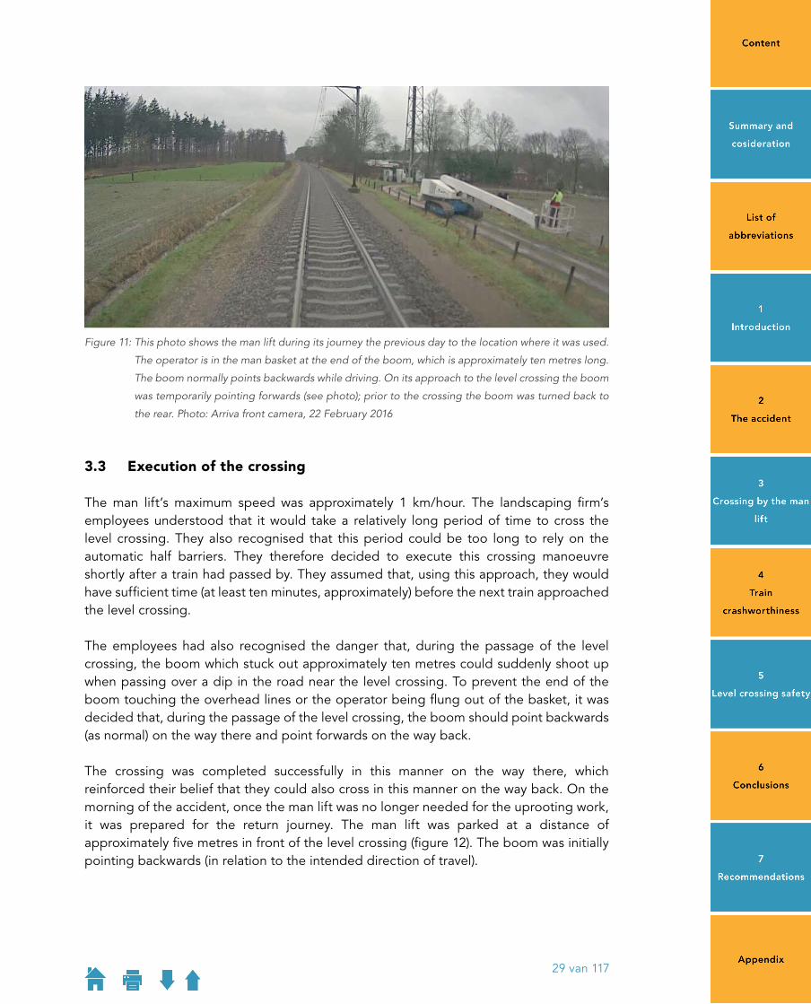
Figure 11: This photo shows the man lift during its journey the previous day to the location where it was used.
The operator is in the man basket at the end of the boom, which is approximately ten metres long.
The boom normally points backwards while driving. On its approach to the level crossing the boom
was temporarily pointing forwards (see photo); prior to the crossing the boom was turned back to
the rear. Photo: Arriva front camera, 22 February 2016
3�3 Execution of the crossing
The man lift’s maximum speed was approximately 1 km/hour. The landscaping firm’s employees understood that it would take a relatively long period of time to cross the level crossing. They also recognised that this period could be too long to rely on the automatic half barriers. They therefore decided to execute this crossing manoeuvre shortly after a train had passed by. They assumed that, using this approach, they would have sufficient time (at least ten minutes, approximately) before the next train approached the level crossing.
The employees had also recognised the danger that, during the passage of the level crossing, the boom which stuck out approximately ten metres could suddenly shoot up when passing over a dip in the road near the level crossing. To prevent the end of the boom touching the overhead lines or the operator being flung out of the basket, it was decided that, during the passage of the level crossing, the boom should point backwards (as normal) on the way there and point forwards on the way back.
The crossing was completed successfully in this manner on the way there, which reinforced their belief that they could also cross in this manner on the way back. On the morning of the accident, once the man lift was no longer needed for the uprooting work, it was prepared for the return journey. The man lift was parked at a distance of approximately five metres in front of the level crossing (figure 12). The boom was initially pointing backwards (in relation to the intended direction of travel).
29 van 117
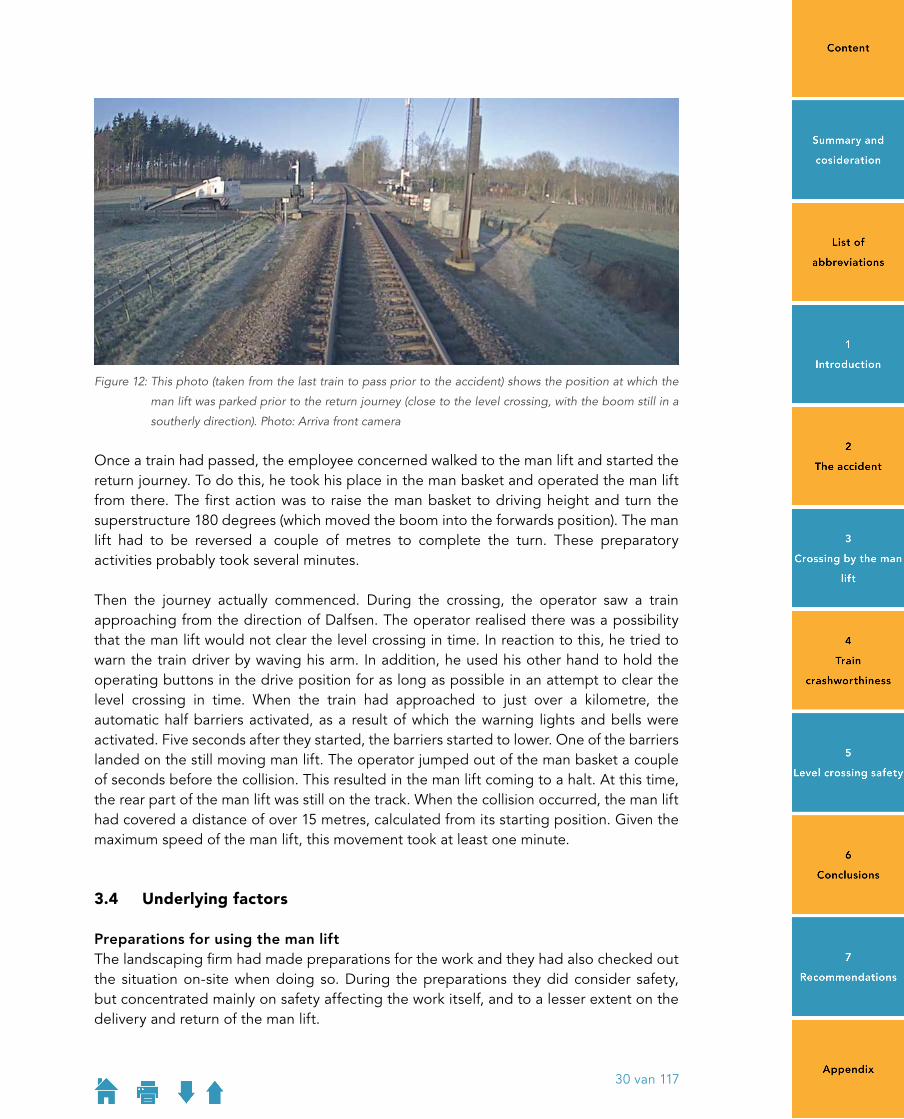
Figure 12: This photo (taken from the last train to pass prior to the accident) shows the position at which the
man lift was parked prior to the return journey (close to the level crossing, with the boom still in a
southerly direction). Photo: Arriva front camera
Once a train had passed, the employee concerned walked to the man lift and started the return journey. To do this, he took his place in the man basket and operated the man lift from there. The first action was to raise the man basket to driving height and turn the superstructure 180 degrees (which moved the boom into the forwards position). The man lift had to be reversed a couple of metres to complete the turn. These preparatory activities probably took several minutes.
Then the journey actually commenced. During the crossing, the operator saw a train approaching from the direction of Dalfsen. The operator realised there was a possibility that the man lift would not clear the level crossing in time. In reaction to this, he tried to warn the train driver by waving his arm. In addition, he used his other hand to hold the operating buttons in the drive position for as long as possible in an attempt to clear the level crossing in time. When the train had approached to just over a kilometre, the automatic half barriers activated, as a result of which the warning lights and bells were activated. Five seconds after they started, the barriers started to lower. One of the barriers landed on the still moving man lift. The operator jumped out of the man basket a couple of seconds before the collision. This resulted in the man lift coming to a halt. At this time, the rear part of the man lift was still on the track. When the collision occurred, the man lift had covered a distance of over 15 metres, calculated from its starting position. Given the maximum speed of the man lift, this movement took at least one minute.
3�4 Underlying factors
Preparations for using the man liftThe landscaping firm had made preparations for the work and they had also checked out the situation onsite when doing so. During the preparations they did consider safety, but concentrated mainly on safety affecting the work itself, and to a lesser extent on the delivery and return of the man lift.
30 van 117

From the landscaping firm’s perspective, the delivery route across the level crossing was the only option. A factor in this could have been that other conceivable options were not very obvious. The location where the man lift was used could not be accessed across the grounds via the paved road on the south side, whereas the south side of Het Lage Veld is hardly recognisable as a road and is, moreover, narrower than the north side.
The man lift rental firm delivered the man lift to the location where it was to be used by truck (low loader) on that day. On that morning, the truck driver noticed that Het Lage Veld was not suitable for his truck because of the lowloader sensitive level crossing there. After consulting with the landscaping firm’s employees by phone, it was decided that the man lift would be unloaded at the start of the road and the remaining distance (approximately 400 metres) would be covered by the man lift itself. This was how the landscaping company had intended it during the planning of the work.
The question of whether the man lift (as opposed to the low loader) could cross the level crossing safely was discussed, but this discussion mainly focused on the risk of electrocution from the overhead lines, the risk of falling out of the man lift at vertical kinks in the road and the options for preventing the caterpillar tracks damaging the road. The risk from the slow moving vehicle crossing the railway was also recognised. Those involved believed that the solution lay in crossing shortly after a train had passed by.
As regards the accident in Dalfsen, during preparation of the work, the delivery and collection of the man lift to/from the location received little attention. This applies both to the landscaping company and to the rental company. The Dutch Safety Board found such a course of action (attention focused mainly on actual activities and not on participation in road traffic) also in an earlier investigation into the causes of road traffic accidents involving agricultural/construction vehicles.8
Training and instructionWhen the man lift was delivered by the rental firm, the truck driver gave the relevant landscaping firm’s employee brief instructions. Those instructions were limited to the operation of the control buttons.
The landscaping firm’s employee who operated the man lift was VCA certified and was doing a man lift course within the scope of his training;9 he also had experience in operating this type of vehicle. He considered himself to be sufficiently competent to operate this man lift.10
The training that the employee was undertaking covers working with a man lift, but this primarily concerns use and operation during the work itself (such as uprooting a tree). Matters such as crossing a level crossing are not covered.
8 Road traffic accidents with agricultural and construction vehicles. Dutch Safety Board, The Hague, 2010.9 The employee had already passed his practical exam, but not the theoretical part of the exam (which he
successfully completed at a later point in time). 10 The Safety Board has no reason to suppose that an operating error contributed to the accident.
31 van 117

Information about available crossing time At an automatic level crossing (as in Dalfsen), the warning lights and whistles announce the approach of the next train. From that moment, a certain period is available in which the level crossing should be vacated. This implies that a certain minimum speed is required to cross the level crossing. However, no minimum speed is required for road vehicles to participate in road traffic or to cross a level crossing. Furthermore, in the Netherlands, in contrast to the United Kingdom (see Section 5.5), road users are not warned by signs about the minimum speed required to safely cross a level crossing.
The landscapers had recognised that more time was needed to cross the level crossing, as compared to the time which was provided by the level crossing installation. The landscapers had assumed that they had at least ten minutes, which was reinforced by the fact that the man lift was well clear of the crossing when the next train had arrived the previous day. However, it is impossible for individual road users to reliably estimate the time at which a subsequent train will arrive. The following considerations apply in this case:
• Due to the asymmetric positioning of the level crossing concerned in relation to the two stations on either side, the period between two successive train passages depends on the direction of the train. Outside of rush hour, trains pass the site of the level crossing every 6 and 24 minutes, alternating from one direction to the other. Between the penultimate train and the train involved in the accident, the level crossing was open to road traffic for slightly longer than five minutes.
• There are additional trains during the morning and evening rush hours. The number of train passages is then eight per hour instead of four. Trains pass the site of the level crossing every six and nine minutes alternately. The crossing on Monday took place between 09:15 am and 09:25 am, approximately, which means it was after rush hour. The crossing on Tuesday took place half an hour earlier, at around 08:48 am. Trains were running at a higher frequency at that time.
• In addition to the regular trains from Zwolle to Emmen, other trains, such as transfer journeys for empty passenger trains or freight trains, also occasionally travel along the track section concerned. Whether or not a train is actually approaching cannot, therefore, be determined by consulting the timetable or other public sources about the rail traffic.
Because there is no publically accessible information about the actual rail traffic, it is impossible for road users to cross a level crossing autonomously if more time is needed for the crossing than the time provided by the level crossing installation. In this instance, only ProRail could provide assistance.
ProRail procedureProRail has stated that, in a situation such as occurred in Dalfsen, those involved should contact the public contact department by telephone. Their telephone number can be found on the ProRail website. ProRail further also pointed out that there is a sticker on every level crossing with a telephone number that can be called in the event of a malfunction. The landscaping firm’s employees involved were not aware of these possibilities. These possibilities are not brought to the attention of level crossing users in an active manner, either. Furthermore, there was no malfunction of the level crossing.
32 van 117

Even if the landscapers had contacted ProRail, this would not have provided a solution in this case: ProRail indicates its processes are not set up to provide a service to individual road users on an ad hoc basis. Staff in the public contact department can provide general advice on crossing level crossings, but cannot provide detailed information about, for instance, the actual train movements on a specific track section. Moreover, they would never make a referral to the relevant traffic controller who is responsible for the track section concerned and who does know the actual train movements. No procedure for doing this has been set up and traffic controllers would, in principle, never cooperate with such a lastminute request.11
Following a serious train accident at Hoek van Holland in 2005 involving an exceptional transport, among other reasons, ProRail and RDW (Netherlands Vehicle Authority) tried to reach an agreement with road hauliers on a procedure to allow this type of transport to cross level crossings safely. The proposal of ProRail assumed that a crossing of less than 10 minutes must be requested no later than 52 hours in advance. This did not result in structural agreements because the road hauliers said that ProRail’s request period was too long. ProRail and RDW did not discuss this issue again until after the train accident in Dalfsen. During this period, no incident reports were received, but exceptional transport may have crossed level crossings which ProRail or RDW were not informed about.
Consultations resumed after the train accident in Dalfsen. ProRail is trying to develop a procedure with a request period that is as short as possible. RDW has, together with ProRail, published guidelines for crossing automatic half barrier crossings with exceptional vehicles. These guidelines are published in Dutch, English and German on the RDW website (see box) and have also been distributed among transport companies as part of a newsletter. In addition, ProRail’s website now addresses the risk of slow vehicles and links to the RDW website.
11 Within this context, ProRail points out that with current safety technology traffic controllers cannot see the exact position of a train if it is on the main line i.e. between two stations so contact with the train driver is then required. The Safety Board considers that, strictly speaking, this is true but even in the current situation it is possible to see whether there is a train is on the main line. On a singletrack track section with a halfhour frequency, as was the case at the accident location, by its very nature there is usually a period of exactly 15 minutes in which the track section is totally free. In addition, preparations are currently in hand to implement modern safety technologies ETCS Level 2 on parts of the railway network. When this system is used, trains report their position at intervals of a couple of seconds. In addition, the system also allows trains to be authorised to certain points (to a specific level crossing for instance) and allows emergency brake orders to be sent to a train. Both options the natural gaps in the timetable and modern safety technology could be used by ProRail to assist exceptional level crossing users to safely reach the opposite side of the track.
33 van 117

Crossing a level crossing with exceptional transportIf you wish to cross a level crossing, you will of course want to do so safely. This article describes how you can best cross a (protected) level crossing.
Rules for safely crossing an automatic level crossing where the barriers are automatically operated by an approaching train (AHOB).*
If you approach an AHOB and a train approaches, the following standard programme is followed: 1. The red lights will light and the bell will be rung for 5 seconds.2. The following 12 seconds the barriers descend to form a barrier halfway across
each side of the road.
The following are a number of rules that should be followed to ensure a safe crossing:1. Always first determine whether there is an alternative route without level crossings.2. In the case of an exceptional transport always request an exceptional transport
permit from the RDW.3. Wait until the red light/s are turned off, a second train can always be approaching.4. Try to start to cross the level crossing while still moving, not from a standing start.5. If the time required for the entire lorry and trailer to cross the last rail is a
maximum of 15 seconds, the level crossing can be crossed safely. No train can be present. Take into account factors that could affect the time taken, such as traffic and tight radiuses on the other side of the crossing.
6. The barriers start to descend after 5 seconds on a standard AHOB. These can come into contact with and damage the truck. A level crossing barrier is constructed in such a way that when the transverse forces are sufficiently high, it will break in a controlled way. In a conflict situation, it is better to break a barrier than to risk a collision with a train. Every motorised vehicle has sufficient power to overcome the resistance offered by the barrier.
7. A vehicle equipped with steel caterpillar tracks is not allowed to cross a level crossing.
8. A transport with limited ground clearance (lowloader) can result in a conflict with a lowloader sensitive level crossing (a crossing that poses difficulties for vehicles with a low ground clearance). These special level crossings are included in the ProRail site, in the socalled Dieplader boekje (Lowloader book). At such level crossings, a warning sign displays a unique number that refers to the Lowloader book. In mid2016, you can ask the RDW which level crossings are lowloader sensitive.
34 van 117
9. If it is not possible to clear the level crossing within 15 seconds (in connection with approaching trains and descending barriers), ProRail must be contacted in a timely fashion (please add contact details) allowing ProRail to take measures to make the transport possible. Note that dependent on the measures that must be taken, a certain preparation time is required. It is impossible to interfere with the train service instantaneously.
The guidelines above also apply to:
• vehicles that take part in events, parades or processions; and• work vehicles; and• to transport over private level crossings.
Box: Information from ProRail and RDW as presented on the RDW website.
Point 7 (‘A vehicle equipped with steel caterpillar tracks is not allowed to cross a level crossing’) was only added to the rules after the accident in Dalfsen. It is therefore reasonable to state that the landscaping firm could be not be aware of the specific additional risks associated with crossing a level crossing with a tracked vehicle.
Appearance of the railway lineWith respect to the accident in Dalfsen the users of the man lift did not accurately estimate the risks associated with crossing the level crossing. The rustic appearance of the railway line may have played a role in this. The landscaping firm’s employees who were involved later admitted that they had absolutely no idea that up to eight trains an hour passed this level crossing at a speed of 140 km/hour. During the investigation, it turned out that this amazement was shared by a number of people. Apparently, the railway line is associated with lower train frequencies and speeds. This expectation pattern may have been influenced by the fact that the railway line is less prominent in the landscape than most other railway lines: for instance, the line is not dualtrack but singletrack, there are no verge ditches and there are many level crossings, some of which are unprotected. It is feasible that such factors contributed to the optimistic estimation of the ease of crossing the railway line. In fact, however, the nature of train traffic and the associated risk on a single track do not differ substantially from the nature of train traffic and the associated risk on a doubletrack main line.
3�5 Other accidents where more crossing time is required
Level crossing collisions between passenger trains and heavy road vehicles that took place in the period between the start of 2005 and the early months of 2016 were analysed to assess whether there have been comparable accidents previously. All level crossing collisions where the road vehicle was heavier than a passenger car, such as trucks, agricultural vehicles and earth moving machinery, were selected. This was a total of 55 accidents, which equates to an average of 5 accidents per year. In comparison, the number of level crossing collisions involving passenger cars in the period concerned was 222, which equates to an average of 20 accidents per year: four times as many.
35 van 117

The analysis, which is described in greater detail in Appendix D, revealed the following:
• There were no other level crossing collisions involving a man lift in the period under consideration. The last time that this type of accident occurred was in 1996 in Naarden.
• The accident in Dalfsen occurred because the road vehicle was driving so slowly that the passage of the level crossing took longer than is covered by the automatic half barriers. This situation also occurred in another accident. This was a crossing manoeuvre involving a mini digger.
• There is also another accident where those involved realised in advance that the crossing manoeuvre would take longer than fits in with the operation of the automatic half barriers. This was a level crossing collision with an exceptionally long truck that occurred near Hoek van Holland in 2005. A factor in the occurrence of this accident was that the truck, due to its exceptional length and the local situation, had to manoeuvre (back and forth) during the crossing.
The Dutch Safety Board concluded that in recent years at least two other level crossing collisions have occurred which, from the circumstances and cause, are comparable with the accident in Dalfsen. We must mention here that the aforementioned incidents did actually result in a collision. ProRail’s figures show that there were a total of 62 nearcollisions with road traffic in 2015, nearly ten per cent of which involved agricultural vehicles.
36 van 117

3�6 Conclusions
The level crossing collision at Dalfsen occurred because the man lift needed too much time to cross safely. The level crossing protection system had a normal warning time, but the crossing manoeuvre for this man lift required approximately three times as much time.
Nevertheless, those involved believed that the crossing was possible because they assumed that the next train would not arrive until ten minutes later at the earliest. The concrete accident threat became clear to the operator when he saw a train approaching during the crossing manoeuvre. However, avoiding the collision was by then no longer an option.
The landscaping firm did not verify the train movements with ProRail. Even if the employees of the company had tried to do this, it would not have helped them any further; ProRail would only have advised not using the level crossing. ProRail is not set up to serve level crossing users on an ad hoc basis.
When making preparations for using the man lift, the firm concerned had mainly studied the work to be carried out (uprooting the tree) and the safety aspects directly related to that work, and to a lesser extent the safety of delivering and returning the man lift itself. That aspect was hardly touched upon in the man lift training or in the instruction provided by the rental firm when they delivered the man lift.
37 van 117
38 van 117
4 TRAIN CRASHWORTHINESS
4.1 Introduction 394.2 Crashworthiness requirements focus on the occupants 394.3 Collapse of the driver’s cab 414.4 Train driver escape options 434.5 Comparison with other accidents 454.6 Crashworthiness acceptance requirements 504.7 Monitoring of build quality 514.8 Conclusions 52

4 TRAIN CRASHWORTHINESS
4�1 Introduction
The consequences of the accident in Dalfsen were very serious in the sense that the train driver lost his life and the train was derailed and toppled over. The train driver died because the train cab was completely destroyed by the forces that were exerted on it during the accident. This was a relatively new type of train and the crashworthiness of the cab complied with the latest acceptance requirements. This means that trains have a specifically designed crash structure to withstand impacts of a specific magnitude. The train concerned was part of a series of trains which display defects in the welds in the crash structure. Train drivers were, therefore, once again reminded to flee the cab if a severe impact was imminent and seek refuge in the adjacent passenger compartment. The above begs the question why did the cab collapse in the accident in Dalfsen and to what extent did the weld defects play a role in this. The extent to which the train driver had an opportunity to leave the cab in good time is also relevant.
4�2 Crashworthiness requirements focus on the occupants
New trains must comply with European requirements, which are concretely elaborated in a set of Technical Specifications for Interoperability (TSIs) and a set of European Standards (EN standards). For the crashworthiness of passenger trains, this is primarily the EN15277 standard (Crashworthiness requirements for railway vehicle bodies).
Historical developmentsThe EN15227 standard is based on two largescale European research projects. The basis was laid by the European Rail Research Institute (ERRI) which conducted extensive research into improving the crashworthiness of passenger trains in the first half of the 1990s. This involved extensive analysis of approximately two thousand train accidents in various European countries, as well as the compilation of an inventory of the knowhow of the participating railway companies. The findings 12 showed that, in the majority of train accidents, the occupants of the trains can be effectively protected with Crash Energy Management (CEM). This means that trains should be constructed so that, in the event of a collision, maximum impact energy is absorbed in a controlled manner by specifically fitted elements such as crash absorbers or crumple zones. The ERRI study also made it clear that, instead of the static tests that were used at the time, design criteria should be developed in the form of reference collision scenarios that a train must be capable of withstanding.
12 The results were published in 1994 in ERRI Report B205; still frequently cited today.
39 van 117

The insights from the ERRI study were elaborated in greater detail in the largescale Safetrain project led and funded by the European Commission. That project was carried out by a consortium of railway undertakings, train manufacturers, technical universities and research centres. One part of the project comprised formulating design criteria in the form of collision scenarios, another part was developing technical solutions. The Safetrain project resulted in the following four test scenarios:
1. Train collides with similar train.2. Train collides with a buffered wagon.3. Train collides with reference vehicle similar to a truck, and, 4. A compressive force against the train’s obstacle deflector.
All scenarios represent common types of collisions. Scenario 1 represents a frontal collision between two trains. Scenario 2 represents collisions with conventional trains or buffer stops. Scenario 3 is intended to simulate a train collision at a level crossing involving a truck at right angles to the tracks, and Scenario 4 to simulate a train collision at a level crossing involving a small road vehicle (bicycle, moped, passenger car or other low object).
Current requirementsThe requirements in relation to crashworthiness currently set by EN15227 13 are that new passenger trains must be demonstrably able to withstand the following four collision scenarios:
1. Collision with an identical train at a speed of 36 km/hour.2. Collision with a buffered 80tonne wagon at a speed of 36 km/hour.3. Collision with a 15tonne standardised truck at a speed of 90 km/hour.4. A compressive force of 300 or 250 kN against the obstacle deflector at 0 and 75 cm
from the centre respectively.
‘Capable of withstanding’ means, among other things, that the passenger compartment is only allowed to deform to a certain extent and that there must be a specific minimum survival space for the train driver in or behind the cab.14 Unlike the original regulations, which mainly specified requirements for the compressive forces that a train must be capable of withstanding, the current requirements focus on the occupants: for them, the decelerations must be limited to a safe level, and certain survival space must remain available.
13 EN Standard 15227 originates from 2005 and has been revised twice since then, in 2008 and 2011 respectively. The revisions did not significantly change the essence of the crashworthiness of passenger trains. This is why the version (200520082011) is only explicitly mentioned in this report when it is relevant. The content of a subsequent revision has been prepared and it is expected to be introduced in 2017.
14 Capable of withstanding also means: reduce the risk of running over an object and the risk of derailment, limit the deceleration and limit the consequences of hitting a low track obstruction.
40 van 117

4�3 Collapse of the driver’s cab
Collision four times heavier than reference collisionOf the prescribed collision scenarios, one (Scenario 3) relates to forceful level crossing collisions. This is a 90 km/hour collision with a reference vehicle with a mass of 15 tonnes standing at right angles to the tracks. The acceptance file for the GTW trains shows that calculations demonstrated that this type of train is capable of withstanding such a collision: some of the impact energy is absorbed by the cab deforming in a controlled manner, so that the survival space for the train driver is retained at the driver’s seat.
By contrast, the train cab was totally destroyed in the accident at Dalfsen. The reconstruction of the circumstances of the accident, which is explained in detail in Appendix C, reveals that the explanation is that the collision in Dalfsen was considerably more powerful than Scenario 3 in EN15227.
The train acceptance file reveals that, in a collision involving this train type in accordance with Scenario 3 of EN15337, a total of approximately 4.1 MJ of kinetic energy is converted into deformation work, of which approximately 2.4 MJ is accounted for by the train; the remainder (approximately 1.7 MJ) is absorbed by the deformable reference obstacle.15
The analysis of the trip data (see Appendix C) revealed that, in the collision in Dalfsen, the speed of the train decreased from approximately 131 km/hour to approximately 107 km/hour. When combined with the masses of the train and the man lift, this change in speed meant that approximately 10.6 MJ of kinetic energy was converted into deformation work in the collision in Dalfsen. In addition, the man lift did break into its main parts (chassis, superstructure and boom) but there was no significant deformation of any of those parts. This can be explained by the fact that the structure of the various man lift components is very strong and rigid. The fact that there was no major deformation of the man lift implies that the majority of the total impact energy (or approximately 10 MJ) was absorbed by the front of the train.
This means that during the collision with the man lift the front of the train had to absorb approximately four times more impact energy than the design intended. The difference is mainly (approximately 75%) the result of the higher collision speed of the train (131 instead of 90 km/hour); the remainder (approximately 25%) is from the man lift having a greater mass (20 instead of 15 tonnes) and a lower centre of gravity, and also being more rigid than the reference vehicle in Collision Scenario 3.
Moreover, in the accident in Dalfsen it is possible that other, considerable forces were exerted on the front of the train even after the collision with the man lift. Although the course of events while the train was decelerating cannot be reconstructed accurately, it is clear that the following two events occurred. Shortly after the first collision, a secondary crash occurred when the man lift came into highspeed contact with an overhead lines pole standing next to the track. Because the man lift was probably still partially in front of the train at this time, considerable forces could have been exerted on the front of the
15 Report AL1240928 GTW GKB/SLTB Crash Analysis, Stadler 10 December 2010.
41 van 117

train in this secondary crash. After this, the front of the train lifted from the track and then ended up in the lowerlying area next to the track. Considerable forces will probably have been exerted on the front of the train during this part of the deceleration, due in part to the train still travelling at a considerable speed. The crashworthiness standard does not specify any requirements for such followon collisions.
Cab frame weld defectsA total of 220 trains of the train type in the accident in Dalfsen are in use; 180 trains with 3 Dutch train operators (Arriva, Connexxion and Veolia ) and 40 trains are in use with 5 foreign train operators. Three months before the accident in Dalfsen, in November 2015, the manufacturer revealed that the crash structures in the cabs of 88 of these 220 trains had not been welded correctly. The train involved in the accident in Dalfsen was one of those 88 trains.
Nature and severity of the weld defectsThe weld issue came to light as the result of an accident that occurred on 06 May 2015 in Übelbach in Austria. Here, two trains of the type concerned were involved in a frontal collision (see the further description of this accident in Appendix E). The investigation revealed that the crash frames of both trains manifested weld defects. Further investigation by the manufacturer revealed that the weld defects exist in the crash frames that were produced by a specific supplier (in the period 2011 2012). The defects relate to incomplete penetration during welding and porosity.
The manufacturer investigated the consequences of the weld defects for the crashworthiness of the affected cabs. This investigation comprised the repetition of the calculations that form the basis for the type approval and acceptance of the trains.16 Using reduced weld thicknesses in the calculations, they assessed the extent to which the cabs with weld defects were capable of withstanding the previously mentioned collision scenarios in EN15227.
In Collision Scenarios 1 and 2 (collisions with other railway vehicles), the crash frames with weld defects do not behave significantly differently than is the case for those without weld defects. In these collision scenarios, the weld defects do not lead to significantly greater deformation of the cab, as a result of which the survival space in the cab remains available.
In Collision Scenario 3, the weld defects do lead to greater deformation of the cab. The difference with the other two scenarios can be explained by the fact that the impact forces in Scenario 3 are exerted higher, and the crash frame in its entirety has to convert more impact energy. The greater deformations only relate to the cab, and not to the adjacent passenger compartment. This means that the survival space for the train driver laid down in EN15227 is still available even with the weld defects, but this is only in the adjacent passenger compartment, not in the cab itself. This means that the trains with weld defects still comply with the standard, even if the cab collapses.
16 Report AL2151876, Untersuchung der Schweissnahtmängel im Crashgerippe, Stadler, 16 March 2016.
42 van 117

Effect on the outcome of the accident in DalfsenAn inspection of the breaks reveals that they sometimes run through the welds, but usually also run through the base material. In addition, deformations were encountered in the base material which indicate that the welds were strong enough to transfer the forces required to achieve that deformation. The deformations and breaks which occurred in various parts of the crash frame show that the crash frame deformed as intended during the collision (see Appendix C.2). As a result of that controlled deformation of the crash frame, an amount of impact energy was absorbed that approximately matches the amount in Collision Scenario 3 in EN15227.
In the collision in Dalfsen, however, the front of the train had to absorb approximately four times as much energy than the controlled deformation of the crash frame allowed for. As a consequence, the deformation in the remaining part of the collision was of such a magnitude that the cab structure collapsed.
The cab structures of the GTW trainsets are not designed to withstand forces of such high a magnitude nor do the admission requirements specify that they should. Also without weld defects, the cab structures would have had to be constructed considerably stronger than required, for them to be able to withstand the forces as they occurred in the Dalfsen collision. Simulation calculations by the manufacturer show that a collision impact as occurred in Dalfsen would have led to a collapse of the cab crash structure, also without weld defects.17
Repair of weld defectsThe manufacturer has developed a modification to repair the cabs with weld defects. This modification comprises bolting steel plates to various locations on the crash frames. According to the manufacturer, implementing this modification makes the crashworthiness of the cabs with weld defects at least equivalent to those without weld defects.18 The intention is to fit the modification to the trains concerned in the second half of 2016, following evaluation and approval by the authorisation bodies.
4�4 Train driver escape options
In the accident in Dalfsen, the driver’s cab was totally destroyed, whereas the passenger compartment behind it did remain intact. Whether or not the driver tried to escape from the cab into the passenger compartment behind it in reaction to the accident threat is not known; he was still in the cab when the collision occurred. The acceptance requirements for the crashworthiness of trains do take account of such an escape manoeuvre: after all, sufficient survival space for the driver must remain in the cab itself or outside the nominal cab area (provided there is immediate access to it).19 This raises
17 GTW Crash Analysis: Dalfsen Collision on February 23rd 2016, B. Castelli and A. Starlinger, 11072016.18 Report AL2151876, Untersuchung der Schweissnahtmängel im Crashgerippe, Stadler, 16 March 2016.19 EN15227 states: ‘The survival space may be located outside the nominal cab area provided that there is immediate
access to it.’ Both options apply to the reference collision at 90 km/hour; the standard does not prescribe anything for collisions at higher speeds. So it is not the case that the standard is based on the principle ‘that the cab must remain intact below 90 km/hour and that the train driver must escape from the cab above 90 km/hour’.
43 van 117

the question, to what extent is it reasonably possible in practice for a train driver to leave the cab in good time if a collision is imminent?
Time needed to escapeIn order to escape to the rear, a driver must:
• see and recognise the danger of a collision, apply the emergency brakes, estimate the intensity of the collision 20 and, based on this information, decide whether or not to escape to the rear;
• turn the chair, get out of the chair, open the cab door and leave the cab (moving against the forces of the applied emergency brakes).
The time taken to complete this process does, of course, depend on situational matters, such as for instance the distance to the point of the collision, and the actions required to turn the chair and to open the door, as well as the physical condition of the train driver. To be able to estimate this, the Safety Board performed a number of practical tests and calculations. This revealed that a period of at least seven seconds must be taken into account for the entire escape process, even longer depending on the situation.
Time availableIn the accident in Dalfsen, the train driver, because of the curve in the track, only gained sight of the level crossing when the train was approximately 350 metres away from it (see photo on the left in figure 13). The accident threat would not, however, have been immediately apparent when the train driver caught sight of the level crossing. This is because there is a curve in the intervening track section, as a result of which it was not, initially, perceptible that (part of) the man lift was still on the level crossing, and that it would probably not clear the level crossing in time. When that too had become reasonably perceptible, the distance from the train to the level crossing had already decreased to approximately 175 metres (see photo on the right in figure 13). The analysis of the trip data (see Appendix C1) reveals that the remaining distance was covered in four to five seconds. This means that the period available for an escape manoeuvre was less than the time reasonably required for it. In the accident in Dalfsen, the train driver did not have the opportunity to make a timely escape from his cab into the passenger compartment.
20 Escaping to the rear is only advisable if a relatively forceful collision is imminent (with a realistic chance of cab deformation). In a relatively light collision (without cab deformation) it is better for the train driver to be as close as possible to the driver’s control panel, to prevent him coming into contact with the control panel or other interior components with a significant speed difference.
44 van 117

Figure 13: View from the cab on approaching the Het Lage Veld level crossing. The left-hand photo is the
moment at which the level crossing becomes visible; the distance is a good 350 metres. The
right-hand photo is the stage at which it was reasonably possible for the train driver to assess the
situation on the level crossing (including any accident threat); the distance had then decreased
to approximately 175 m. These pictures were recorded during a train journey on a similar train on
01 March 2016.21 Photos: Police
4�5 Comparison with other accidents
To evaluate the extent to which the course of events of the accident in Dalfsen is representative of other level crossing collisions, an inventory was compiled of comparable accidents that occurred in recent years.
Level crossing collisions where the driver was injuredIn the vast majority of the level crossing collisions it was only the road user involved in the collision who suffered serious consequences. In recent years there have been two other level crossing collisions, apart from Dalfsen, where the train driver was seriously injured.
Level crossing collision at WijheOn 3 November 2005, a passenger train collided with a laden truck at a level crossing in Wijhe with an impact speed of approximately 125 km/hour. Both the truck and the train suffered serious damage; the truck driver died and the train driver was seriously injured.
Level crossing collision at AssenOn 17 June 2003, a passenger train collided with a military tracked armoured vehicle at a level crossing in Assen with an impact speed of approximately 110 km/hour. Two occupants of the armoured vehicle died, a third occupant suffered injuries. The train driver sustained serious injuries.
21 The train that was involved in the accident was fitted with a front camera, but as a result of the collision the last recorded pictures were not saved.
45 van 117

Figure 14: Wijhe (2005), train driver seriously injured as a result of level crossing collision with truck. Photos:
IVW (left), Dutch Safety Board (right)
Figure 15: Assen (2003), driver of passenger train seriously injured as a result of level crossing collision with
an armoured vehicle. Photos: TCOD-report “Botsing YPR met trein nabij Assen op 17 juni 2003”
All three level crossing collisions (Dalfsen, Wijhe and Assen) resulting in serious injury to or the death of the train driver involved a highspeed collision (from 110 to 130 km/hour)
46 van 117

into a large and heavy road vehicle (a man lift of approximately 19.5 tonnes, a laden truck of approximately 21 tonnes and an armoured vehicle of approximately 13.5 tonnes respectively).
Train driver escape optionsFour level crossing collisions were identified where it is known that the train driver attempted to escape and for which sufficient information is available to make an estimate of the time that was available for that escape attempt. The relevant details of these four accidents are included in Table 1.
location Dalfsen Assen Wijhe Houthem Maarheeze
date 23-2-2016 17-6-2003 3-11-2005 8-12-2009 22-7-2010
train type GTW VIRM VIRM GTW VIRM
road vehicle type
man lift armoured vehicle
truck truck truck
direct cause man lift did not clear of level crossing in time
road vehicle drove onto level crossing when train was close
road vehicle drove onto level crossing when train was close
road vehicle not clear of level crossing in time
road vehicle not clear of level crossing in time
train approach speed
approx. 140 km/h
approx. 125 km/h
approx. 130 km/h
approx. 100 km/h
approx. 140 km/h
distance at which the train driver could see the accident threat
approx. 175 m approx. 165 m not known approx. 400 m ≥ 400 m
time at which train driver applied the emergency brakes
approx. 3½ s before collision
approx. 4 s before collision
approx. 4 s before collision
approx. 9 s before collision
approx. 13 s before collision
train collision speed
approx. 130 km/h
approx. 110 km/h
approx. 125 km/h
approx. 65 km/h
approx. 85 km/h
train driver attempted to escape
not known yes yes yes yes
escape successful no no no yes yes
Table 1: Dalfsen accident compared with other level crossing collisions, where it is known that the train driver
attempted to escape.
In two accidents (Houthem and Maarheeze), the train driver succeeded in leaving the cab in time. Common to these two cases is that the road vehicle was stranded and was on the level crossing for a relatively long period of time. In addition, the train driver had already applied the emergency brakes at a relatively early stage (9 and 13 seconds before the collision respectively) in both cases, which means that at the time they saw the accident threat they also recognised it as such.
47 van 117

In the other two accidents (Assen and Wijhe), the train drivers did not succeed in leaving the cab in time, as a result of which they sustained serious injuries. These two accidents involved road vehicles that only entered the level crossing when the train had approached to within a relatively short distance. As a result of this, the accident threat only became apparent to the train driver at a relatively late stage in these two cases. This is reflected in the fact that, in both cases, the train driver applied the emergency brakes relatively late, i.e. approximately four seconds before the collision; a time frame comparable with the accident in Dalfsen.
These examples illustrate that there is insufficient time available for the train driver to escape to the rear from the cab in good time in highspeed level crossing collisions with a heavy obstacle where the train driver can only recognise the accident threat at a late stage.
Crashworthiness of Stadler trainsAs a result of the accident in Dalfsen, the VVMC union expressed its concern about the crashworthiness of Stadler trains. In addition to the serious outcome of the accident in Dalfsen, these concerns were based on media reports on three other fatal accidents involving trains by the same manufacturer, as well as the weld defects already mentioned in some of the GTW trains. Investigation has provided the following insights in relation to these concerns.
Accident in DalfsenIt is highly exceptional for a train driver to be killed in a level crossing collision. It is more than 25 years since an accident of this type occurred in the Netherlands.22 The fact that the cab collapsed in the accident in Dalfsen cannot be explained by any defect in the train or the train type as explained earlier in this chapter but on the fact that it was a forceful collision.
Other accidents involving Stadler trainsAs a result of the accident in Dalfsen, reports appeared in domestic and foreign newspapers according to which there had been four accidents involving Stadler trains (including the accident in Dalfsen) within a period of ten months in which a total of seven train drivers were killed. The three other cases, which are described in more detail in Appendix E2, occurred abroad. These were: a collision between two trains at Bad Aibling (Germany), a level crossing collision involving a passenger train and an agricultural vehicle at Ibbenbüren (Germany) and a collision between two passenger trains at Übelbach (Austria).
These other three accidents appear to substantially differ from each other, both in terms of the circumstances and in the type of train involved. The accidents must therefore be assessed individually, which presents the following picture:
22 This was a level crossing collision between a passenger train and a private car which occurred in Tietjerkstradeel on 29 July 1988, where both the truck driver and the train driver were killed.
48 van 117
• The accident in Bad Aibling was a frontal collision between two trains at a very high relative collision speed. The track section speed there was 100 km/hour, and both trains had barely slowed down before the collision. The collision speed (the sum of both train speeds) was about 150 km/hour. In essence, the current acceptance requirements for passenger trains demand that the front of the train must be capable of withstanding a frontal collision at a relative collision speed of 36 km/hour. The collision at Bad Aibling was, therefore, many times more powerful 23 than the reference collision (Scenario 1 of EN15227) which passenger trains must be capable of withstanding in accordance with the current acceptance requirements. The fact that the driver’s cab collapsed in this accident cannot, therefore, be used to deduce that the crashworthiness of the type of train involved must be suspect.
• At first sight, the accident in Ibbenbüren has similarities with the accident in Dalfsen. That accident was also a level crossing collision with a relatively heavy vehicle (a manure spreader in this case) and the driver’s cab was also completely destroyed. Visually, the appearance of the cab of the train concerned seems to be the same as that of the GTW trains, but in fact this is a different type of train (a first generation FLIRT) that does not comply with the requirements of the standard EN15227. An important difference is that the cabs of that type had not yet been fitted with a crash structure as is usual and mandatory for trains nowadays. The accident at Ibbenbüren cannot, therefore, be used as the basis for concluding that modern trains are unsafe.
• The accident at Übelbach was the accident where the weld defects discussed earlier in this document came to light. The Austrian Sicherheitsuntersuchungsstelle des Bundes (SUB) carried out an investigation into that accident.24 The investigation report 25 concerned did not examine the extent to which the consequences of the accident could have been influenced by the weld defects. The report did mention that the relative collision speed (the sum of both train speeds) was over 70 km/hour. This means that in this accident the collision speed was approximately twice as high as the reference collision (Scenario 1 of EN15227) that the front of the passenger trains should be capable of withstanding in accordance with current acceptance requirements. This implies that the amount of impact energy that had to be absorbed by the fronts of the trains was approximately four times as high as required by current acceptance requirements
As regards the concerns about the safety of train cabs and the potential effect of the weld defects, it can also be ascertained that, in addition to the accidents at Dalfsen and Übelbach, there was another accident involving a GTW train where the crash frame was affected by weld defects. This was the level crossing collision that occurred at Ruurlo on 16 July 2014 (see the detailed description in Appendix E.3). Although it was a relatively forceful collision (at a collision speed of approximately 80 km/hour) with a loaded truck, the driver’s cab remained intact in this accident, despite the weld defects.
23 The fact that the collision speed was probably at least four times this speed (150 instead of 36 km/hour) implies that the amount of impact energy that had to be absorbed by the fronts of the trains was probably 16 times higher than demanded by the current acceptance requirements.
24 In Austria the SUB (which is comparable to the Dutch Safety Board in the Netherlands) formally serves as the national investigation agency for train accidents.
25 Rapport Kollision Z8762 und Z8787 nächst Vstu Waldstein (StLB) am 06. Mai 2015, BMVIT795.365IV/BAV/UUB/SCH/2015 (03062016).
49 van 117

The Safety Board indicates that the three aforementioned accidents, just as the accident in Dalfsen, in one or more ways are not within the scope of the current crashworthiness requirements. They therefore do not give rise to any specific doubts regarding the crashworthiness of Stadler trains. The accidents do, however, emphatically illustrate that the train driver’s workspace is dangerous when accidents occur that are significantly more forceful than the reference collisions prescribed in the collision standard. The fact that a train meets the norm does not provide absolute certainty, therefore, that the driver is safe in the event of an accident.
4�6 Crashworthiness acceptance requirements
In the accident in Dalfsen, considerably higher impact forces were exerted on the driver’s cab than it should be capable of withstanding in accordance with the current acceptance requirements. In level crossing collisions, this situation appears to occur especially when there is a collision at a relatively high train speed (100 km/hour and upwards) into a relatively heavy road vehicle (such as a truck, man lift, etc.).
We are aware of three such level crossing collisions in the Netherlands from the last 13 years where the train driver was seriously or even fatally injured (Assen, Wijhe and Dalfsen). In the period concerned, there were over 300 level crossing collisions involving motor vehicles. This means that the train driver was seriously injured in slightly less than 1% of such accidents. The question is, how effective is it to make all trains suitable for withstanding the most severe collisions? Even if the decision to do this were taken, it would be a long time until the effects became noticeable because of the long servicelife of railway rolling stock. To reduce the risk of a train driver being injured in a level crossing collision in the short term, the Safety Board therefore believes that the main thrust of work should be in preventing the forceful level crossing collisions themselves.
In the accident in Dalfsen, the train driver did not have the opportunity to make a timely escape from his cab to the rear. This was because the train driver could only see the threat of an accident late, because of the curve in the track. This arises also in other situations, when a road vehicle continues to drive onto the level crossing even though the train has already approached to within close proximity, for example. In these cases, the train had usually only braked shortly before the collision and had therefore decelerated little, so that the collision speed was relatively high. This supports the argument that cab frames should be constructed such that the train driver’s survival space continues to exist within the cab itself, even in forceful collisions. According to the current version of the acceptance requirements (EN15227), the minimum survival space prescribed for the three collision scenarios may exist outside of the nominal cab space if it is immediately accessible.26 The standard concerned is, however, currently being revised,27 and the revised version, which is expected to be published mid2017, will probably no longer include the escape option to the passenger compartment behind the cab.
26 EN152272011 states: The survival space may be located outside the nominal cab area provided that there is immediate access to it.
27 The Technical Committee CEN/TC 256 (railway applications) is currently revising the current version (EN15227+A1:2010). We anticipate the revised version being published mid2017 (as EN15227:2017).
50 van 117

This tightening of the requirements does not mean that there will be a guarantee of sufficient survival space for the train driver remaining in the cab in future trains in the event of an accident such as the one in Dalfsen. As already explained, the collision in Dalfsen was, after all, considerably more forceful than the reference collisions referred to in the regulation concerned. Additionally, the revised version also allows for the driver leaving the driver’s seat and moving to somewhere else in the cab to reach the survival space. In a certain sense, this is also an escape, but over a smaller distance and without having to pass through a door. Whether this will be significantly quicker than the seven seconds mentioned previously has yet to be found out.
4�7 Monitoring of build quality
The fact that the weld defects could remain undetected in some 90 GTW trains during manufacture is because the quality of welds was only inspected after the welding had been completed, and that inspection was visual only (not using ultrasound or xray equipment ). The choice of this inspection regime means that insufficient importance was attached to the soundness of the welds concerned. The manufacturer has indicated to endorse this conclusion and has implemented measures.
It is striking that also the certification and acceptance process for trains did not bring to light that the weld quality was inspected in this way during manufacture. Within the framework of the certification and acceptance of trains, there is generally no physical testing of individual trains. Instead of this, the legislation makes do with testing the way in which the quality of the construction process is monitored. The fact that the weld defects in the GTW trains only came to light after an accident involving those trains means that this form of external supervision did not deliver the intended result in this case, namely an independent determination that only a sound train is admitted on the rails.
After the GTW trains concerned were built (2010 2012), the Fyra parliamentary inquiry has also taken place. The inquiry committee investigated the problems with the Fyra trains. The inquiry committee concluded that there were insufficient internal and external controls on the construction quality of the trains concerned. The Fyra parliamentary inquiry led to recommendations for improving the certification and acceptance of new trains.28 The Safety Board has not, therefore, further investigated this aspect.
The manufacturer of these trains has stated that it has learned from this situation. In the design of newer trains a construction is chosen that is easier to manufacture. In addition, it is evidently not sufficient to rely on a supplier’s certification: proper instructions to and monitoring of the supplier is required, even if it is certified.
28 De reiziger in de kou, Parlementaire enquêtecommissie Fyrarapport, kamerstuk 33 678, nr. 11, 28 oktober 2015
51 van 117

4�8 Conclusions
The accident in Dalfsen involved a relatively new train, of a type that was designed and accepted based on the current crashworthiness standard (EN15227). Among other things, this standard requires that sufficient survival space remains in the cab itself or in the neighbouring passenger compartment when the train collides with a (standardised) 15tonne truck standing at right angles to the track with an impact speed of 90 km/hour. The fact that the driver’s cab in the accident in Dalfsen was totally destroyed despite this is because that collision was approximately four times more forceful than the prescribed reference collision. The difference is primarily (for approximately 75%) the result of the train’s high collision speed; the remainder is the result of the high mass, low centre of gravity and the rigidity of the man lift. Moreover, in the accident in Dalfsen considerable forces were probably also exerted on the front of the train after it collided with the man lift, as a result of crashing into an overhead lines pole and the derailment of the train.
The train involved in the accident at Dalfsen had weld defects in the cab crash structure. The weld defects did not have an effect on the collapse of the cab in the accident in Dalfsen. In this collision, these forces were of such a magnitude that even a cab without weld defects would have collapsed.
We do not know whether or not the train driver attempted to escape from the cab into the passenger compartment. There was insufficient time available to successfully complete any escape attempt. The threat of accident was, after all, only apparent approximately four and a half seconds before the collision, while at least seven seconds is required to escape.
Level crossing collisions involving injury to train occupants are primarily collisions where the train approaches at high speed, does not brake until shortly before the collision and then collides with a heavy road vehicle. This type of forceful level crossing collision must be prevented if safety is to be improved.
52 van 117

53 van 117
5 LEVEL CROSSING SAFETY
5.1 Introduction 545.2 No action framework for clearance problems 545.3 Risk assessment of level crossings 555.4 Number of level crossings 585.5 Comparison with other countries 645.6 Conclusions 69

5 LEVEL CROSSING SAFETY
5�1 Introduction
In the Dalfsen accident, both the operator of the man lift and the driver of the train, after they realised the accident was imminent, had no realistic option to respond adequately. This begs the question to what extent the possibilities for a timely warning are used in such situations. The findings regarding this question are summarised in section 5.2.
In the accident in Dalfsen the severity of the consequences was, to a significant extent, determined by the train approaching at a high speed and its limited degree of braking because of the curve in the track. In addition, the large mass and the rigidity of the man lift played a role. The Safety Board investigated the extent to which that combination of factors is considered in the risk assessment for level crossings. The findings are summarised in section 5.3.
Furthermore, in the Dalfsen accident, it is noteworthy that despite the maximum speed of 140 km/hour the railway line has a high number of level crossings. The Safety Board investigated how this situation has arisen and to what extent that aspect is given attention in level crossing policy (see section 5.4).
In order to be able to assess the identified aspects in a broader perspective, section 5.5. contains a comparison with the situation in other WestEuropean countries.
5�2 No action framework for clearance problems
The inability to clear in time is a frequent accident causeThe man lift did not clear the level crossing in time in the accident in Dalfsen. A fairly large proportion of accidents involve a road vehicle failing to complete in time a crossing that has already commenced. Of the level crossing collisions involving heavy road vehicles, 71% can be traced back to the level crossing not being cleared in time, for instance because the vehicle has stranded, is manoeuvring or because the driver believes he has left the intersection while this is not actually the case. This happens in an average of three accidents each year (see the explanation in Appendix D also).
Action framework for road users during the crossingThe level crossing protection concept leaves it entirely up to the road user to clear the level crossing in time. If a road user fails to do so, there is not much he can do. The man lift operator tried to warn the train driver with arm gestures. He did not have any other options: Dutch level crossings do not have an emergency button to alert trains or send an automated message to the train driver if there is an obstacle on the level crossing.
54 van 117

Running towards the train, making an emergency call to 112 or to ProRail’s number used to report a malfunction of the level crossing usually takes too long to be able to effectively warn an approaching train. In principle, identifying a blocked level crossing in good time is left to the personal observations of the driver of an approaching train.
Action framework for the train driverOne problem that played a role in the accident in Dalfsen was that the curve in the track prevented the train driver from seeing the blocked level crossing until the distance was already too small to brake the train to any significant extent, let alone bring it to a halt before the level crossing in time. To have had that opportunity at the track speed of 140 km/hour that applied there the danger would have had to be identified at a distance of at least approximately 800 metres.29 At that distance, however, the train driver will not always be able to see the situation on the level crossing well enough. Therefore, on level crossings where the visibility conditions are not good, there is a higher risk of (serious) level crossing collisions.
Automatic obstacle detection: modest optionsBritish research (see Appendix F) reveals that, from a technical standpoint, obstacle detection is quite feasible, but that its largescale implementation at (or as a replacement for) level crossings with half barriers is not logical. Level crossings with half barriers purposely have short warning times because if the warning time was long people would circumvent the barriers with all the dangers that entails. However, it is not possible to successfully identify an obstacle, warn the train driver and to brake the train in that short warning time.30
Nor will level crossings be replaced with grade separations in the short term. That means that, in the coming decades, there will still be many level crossing where (just as now) the train driver himself will have to identify an obstacle. The way in which the level crossing risks are assessed does not, however, consider the extent to which the train driver has the opportunity to do so.
5�3 Risk assessment of level crossings
The level crossing register determines risk based on underlying factorsNowadays,31 ProRail assesses level crossing safety based on underlying factors that play a role in level crossing safety.32 A number of factors are recorded for each level crossing in what is known as the level crossing register, and a risk score is awarded to every level crossing based on this (see box). Level crossings are awarded between 1 and 16 points,
29 A braking distance of 630 metres (when decelerating at 1.2 m/s², which equates to a speed reduction of 4.3 km/hour per second), plus 5 seconds (approximately 200 metres) to identify the danger, apply the brakes and as the reaction time for the brakes to develop their full braking capacity.
30 Rail Safety & Standard Board/Arthur D Little, Research into obstacle detection at level crossings, 2006.31 ProRail has been using the level crossing register for a number of years now and, every year, they check if
improvements could be implemented in the register. 32 Because few incidents occur per individual level crossing, the number of incidents occurring at a level crossing
does not present a clear picture of the safety of a level crossing according to ProRail. Such an indicator would vary to a great degree depending on whether or not an accident had incidentally occurred at the level crossing concerned.
55 van 117

where 1 is the most favourable and 16 the least. It is not, incidentally, a linear scale. A higher points score indicates a more than proportionally higher risk. According to ProRail, the Het Lage Veld level crossing in Dalfsen scores five points. With such a score, a collision between a train and a level crossing user would occur once every 150 years according to ProRail. It is not the level crossing register alone that is used in assessing the safety of a level crossing; in all cases a ProRail expert in the field also makes an assessment.
The register helps ProRail to identify relatively unsafe level crossings and, according to ProRail, it provides a ‘common language’ for all those involved in level crossing safety. The level crossing register is also used for the safety assessment in the National Level Crossing Improvement Programme.33
Risk factors in the level crossing registerThe following risk factors are taken into account for level crossings protected by barriers:
• number of tracks;• station platforms accessible via level crossing;• number of trains per hour;• spread of closing duration;• number of carriageways;• presence of traffic island;• cycle traffic facilities;• clearing situation for road traffic;• presence of road paving;• road traffic speed;• cycle traffic intensity;• presence of characteristics that could distract the level crossing user;• presence of characteristics that could irritate the road user.
Risk factors bear little relationship to the severity of the outcomeIt strikes the Safety Board that the risk factors in the level crossing register are primarily factors that influence the probability of a collision, and there are hardly any factors that determine the severity of the outcome. In the accident in Dalfsen, the high train speed, the late moment at which it was clear to the train driver that the crossing was not clear and the mass of the obstacle played a prime role in the severity of the outcome. None of these factors are included in the level crossing register.
In regard to the nature and number of level crossing users, ProRail stated that this is a difficult factor to establish because ProRail does not know the traffic situation at every location. ProRail believes this is a task for the road manager. However, this does not
33 In addition to using the level crossing register (for the safety assessment) another instrument, which charts how level crossings hinder road traffic, is used in the assessments of level crossings within the scope of the National Level Crossing Improvement Programme.
56 van 117
detract from the fact that the intensity and nature of the road traffic is a risk factor that should be included in the risk assessment. If there are many 34 or heavy road users, the risk of a blocked level crossing is high, whereas if the number of road users is very low the question is whether the level crossing still serves any purpose or whether it is only relevant for certain types of traffic. Therefore, it is always important to know how the level crossing is actually used. Therefore, knowing about the actual use of the level crossing is always important.
As regards being located on a curve, ProRail argues that this does not increase the probability of a collision, but does increase the consequences due to the higher risk of derailment. The accident in Dalfsen reveals that the location of a level crossing in or shortly after a curve does affect the probability and severity of the collision. The reason is that a train driver must assess the situation on the level crossing from a fairly great distance. If there is a curve just in front of the level crossing, this hampers the train driver in properly estimating the situation on the level crossing, increasing the likelihood that an imminent danger is not observed in time. If the situation is detected after all at a later stage, the impact speed is high so that the severity of the collisions will also be higher.
As regards train speed, ProRail argues that this factor is irrelevant, because the higher the speed of the train traffic, the longer the notification distance to the level crossing, so that the warning time for road traffic effectively stays the same. The risk does increase at higher speeds: firstly, a train driver must be able to identify any obstacle from a greater distance, which will be more difficult. Secondly, the residual impact speed in a collision will be higher. The train takes more energy into the collision and therefore has a greater potential for inflicting damage.
ProRail states that, prior to the creation of the level crossing register, various studies were undertaken to determine which characteristics of a level crossing are relevant to assessing its safety. According to ProRail, this did not produce a widely supported picture. Therefore, the factors that are included in the level crossing register were decided based on the estimates of experts.35
In addition, ProRail wants to include a manageable number of factors in the level crossing register; after all, all factors must be kept up to date for every level crossing. However, the Safety Board believes that the situation in (or just after) a curve and the maximum speed are such constant factors that little additional effort is required to include them in the register and keep them up to date.
34 The relationship between the number of level crossing users and the number of accidents is not linear for all accident types. That was shown in an investigation that was performed In the United Kingdom after an accident in 1986, in which a train was derailed following a collision with a minibus. In addition to an occupant of the minibus, eight occupants of the train died. A startling conclusion was that the probability of a level crossing collision is greatest on moderately busy roads. This is because, on busy roads, there is a greater probability of cars already being stationary short of the level crossing while the train is still some distance from the level crossing. The waiting cars reduce the chance that a motorist who is approaching the level crossing exactly at the time that the train is also nearby, fails to notice the level crossing and drives on just in front of the train. The relationship that was discovered applies to motor vehicles mistakenly entering the intersection. This relationship does not apply to clearing the level crossing in time. (Automatic open level crossings a review of safety; P.F. Stott, 1987).
35 Report 00123, Substantiation document for level crossing register, ProRail, 2011.
57 van 117
5�4 Number of level crossings
Inconspicuous existence of the level crossingHistorical maps show that the road ran straight on before the railway line was built; when the railway line was built (around 1900), the road situation changed and there is now a level crossing at the current location (figure 16). The situation of the road changed once again since then and this probably happened between 1910 and 1935. The road situation, which is not ideal by current standards because of the bend in the road shortly before the level crossing and the inability for low loaders to use the level crossing, was established long ago and has not changed substantially since then.
On the south side of the track in particular, the road is not flat, is narrow, has numerous bends and can, moreover, be boggy. Het Lage Veld is therefore not suitable as a connecting road between Tolhuisweg and Hammerweg; in addition, Vlierhoekweg lies approximately 300 metres to the east: this is a straight, paved road connecting the same two roads. The Het Lage Veld level crossing is almost exclusively used by nearby residents and pedestrians.
Both the road manager and the railway network manager inspect the level crossing regularly; the railway network manager once every three years and the road manager once every two years. Neither of the organisations found the level crossing to be remarkable: there is hardly any traffic, the level crossing is relatively well protected (the same line has numerous level crossings on comparable roads, without active protection) and there is no history of complaints or accidents on the level crossing. The presence of the level crossing as such is considered to be a given.
There is a difference in perspective between the two managers. Road managers tend to focus on the advantage of a level crossing as it enables road users to cross the railway to reach the other side. Moreover, there are usually only a couple of level crossings (a few dozen at maximum) within their management area, with relatively infrequent accidents. So road managers tend to have little incentive to remove level crossings.
The railway network manager’s perspective is totally different: within its management area there are thousands of level crossings and most serious accidents on the railway network occur on these level crossings. From the railway network manager’s perspective, the level crossing is a source of danger and disruption of rail traffic services, and a dangerous option for crossing the railway. ProRail therefore considers removing level crossings or replacing them with grade separations.
58 van 117

level crossing
level crossing
Figure 16: Het Lage Veld level crossing, maps dated 1908/1911 (upper) and map dated 2015 (lower). Source:
Kadaster
59 van 117

Although the nearby Vlierhoekweg level crossing is less hazardous with regard to crossing heavy vehicles because of the straight and flat road layout, the probability of problems during the crossing is smaller; because of the distance to the curve in the track, the probability of a serious outcome also is smaller the normal processes of the road manager and rail network manager have never considered removing the Het Lage Veld level crossing or restricting its use by long or heavy vehicles.36
Development of the Zwolle - Emmen railway lineIn addition to the Het Lage Veld level crossing, the Zwolle Emmen railway line has many more level crossings, on average one every 700 metres approximately. This is explained by the fact that, when the railway line was built, various legal forms of exploitation existed for railways: mainline railways and local railways.37 At that time, guarded level crossings had to be used on mainline railways. In other words, there was a level crossing guard to operate the level crossing and to ensure that it was free before a train was allowed to approach the level crossing. Because the level crossings were manned, running costs were high. The simplerdesign local railways were allowed to use unguarded level crossings also. The speed was limited on such local railway lines, of which Zwolle Emmen was one.
This speed limit was seen as a limitation for rail traffic services. Following a request from NS, the Minister of Transport, Public Works and Water Management designated the Zwolle Emmen railway line a mainline railway in 1961, so that the speed could be increased to 100 km/hour. Modernisation of the line followed in the 1980s. The line was electrified and equipped with new safety systems, the maximum permitted speed was increased to 140 km/hour and parts of the line were made doubletrack. These expansions allowed for a more attractive train service for rail passengers: from 1987, in addition to a single local service once an hour, which took approximately 70 minutes, a fast service, which completed the journey in just over 50 minutes, could run between Zwolle and Emmen every hour as well. Both times around 1961 and around 1987 level crossings were modified and level crossings were removed, At some point, the Het Lage Veld level crossing was equipped with automatic warning lights (AKI), which in their turn were replaced by automatic half barriers (miniAHOB) around 2005. This occurred within the scope of a replacement programme when near enough all warning light systems nationwide were converted to level crossings with barriers. The usefulness and need for a level crossing that was to be converted was not taken into consideration. When the railway line was modernised, level crossings were removed, but an aboveaverage number remained despite this.
Former local railway linesThe railway lines that were originally laid as local railway lines still have approximately twice as many level crossings per track kilometre as railway lines that were originally laid as mainline railways. In addition, the proportion of unguarded level crossings on former local railway lines is 30%, compared with 15% on the current InterCity network.38 On the former
36 The use of the level crossing is restricted for low loaders.37 Even today, there is a difference in legislation for mainline railways and local railways; however, the latter now
mainly covers tram and metro lines.38 See Appendix D for further substantiation of these figures.
60 van 117

local railway lines, the probability of a level crossing collision between a train and a motor vehicle turns out to be twice as high per kilometre travelled as on railways that were laid as mainline railways from the start. This is the case for over 200 kilometres of line.
InterCity network
regional (mainline)
regional totaal
length (km) 1,406 704 215 2,324
proportion of train kilometres 75% 20% 5% 100%
number of level crossings 1,027 632 343 2,002
of which unprotected 15% 27% 30% 21%
distance between level crossings (km)
1.37 1.11 0.63 1.16
level crossing collisions per million train kms
0.21 0.20 0.53 0.22
Table 2: Characteristics of various types of line.
Apart from the railway line itself being improved over the years, train movements have also increased over time. The level crossing safety policy as laid down in the Third Railway Safety Framework Document specifies that nowadays a risk assessment must be conducted on a change in the use of level crossing. This was the case when, for instance, Arriva took over the rail service from NS in December 2012. Arriva submitted a request to ProRail for a timetable running eight trains per hour (in both directions combined) during the rush hour. The frequency operated by NS in the rush hour had been five trains an hour up until then. ProRail carried out its own risk assessment of this and also had an engineering bureau carry out a risk assessment. Their own assessment did not judge the increase in risks as a result of the increase in frequency to be significant. Neither their own assessment nor that by the engineering bureau identified the level crossings protected by automatic half barriers as a problem.
Arriva trains run at 140 km/hour, just like NS trains had done since the modernisation of the railway line in 1987.39 That speed is normal in railway terms and, because the speed was not increased, there was no reason to conduct a risk assessment from the perspective of those involved. The result of this is that speed was not taken into account in the risk assessment precisely where train speeds are the highest.40
The risk assessments are based on an analysis in relation to the situation that already existed previously. The train speed (which had applied since 1987) and the many level
39 Arriva needs the high speed of 140 km/hour to operate the timetable. This relates, on the one hand, to the agreements with the contracting authority in respect to quick and frequent public transport and, on the other hand, to technical timetabling characteristics: to be able to operate a 15minute service on a single track line, trains must be able to cover the distance between two passing loops in 7.5 minutes. To do this, Arriva uses the options afforded by the infrastructure.
40 In the Netherlands, trains speeds exceeding 140 km/hour only occur on the highspeed line between Amsterdam and Belgium.
61 van 117

crossings on the line (the majority of which have existed since the line was laid) were taken as a given.
Level crossing safety policyFor many years, the policy on level crossing safety has focused on further reducing the number of fatalities. In the first half of the 1990s, there were approximately 40 to 50 fatalities at level crossings each year. This has fluctuated between 10 and 20 since 2004. According to the parties involved, this decrease can be explained by better protection of level crossings (by converting warning light level crossings to automatic half barrier level crossings), by the removal of level crossings and by education and enforcement. The number of level crossings has been reduced from approximately 3100 at the end of the 1990s to approximately 2500 now. The policy objective is to further improve level crossing safety.
Since 2014, The Ministry of Infrastructure and the Environment and ProRail have been shaping the National Level Crossing Improvement Programme. They have been collaborating with road managers on an areaoriented approach to improving safety and the flow of traffic across level crossings. In doing so, they have attached importance to the waiting times, as this improves both the traffic flow and safety.
The Third Railway Safety Framework Document lays down the ‘nounless’ principle for new level crossings; in other words, no new level crossings will be constructed and the use of a level crossing (e.g. higher frequency of train traffic, higher intensity of road traffic, higher train speed) cannot be permitted unless a risk analysis can demonstrate that the safetyrisks of the new or changed level crossing can be managed. The Rail Traffic Policy Incentive an update of the Third Railway Safety Framework Document lays down that, in addition to removing or protecting level crossings or turning them into grade separations, attention must also be devoted to a wider range of measures and that (due to the significantly reduced numbers of accidents on level crossings) safety must be assessed primarily on the basis of the underlying risk factors.
Removing level crossingsIt is ProRail’s ambition to remove a minimum of 20 level crossings every year. Given the efforts required and the lead time associated with this, ProRail is selecting the level crossings that hold the greatest risk. According to ProRail, the Het Lage Veld level crossing could be removed, but it was not part of the group of level crossings whose removal is most urgent. Efforts were therefore focussed on other level crossings, such as level crossings where both train traffic and road traffic is very heavy.
If a level crossing is removed, the road manager is the party that initiates the withdrawal procedure. If the rail network manager and the road manager cannot reach agreement, this could result in a managerial impasse such as the Dutch Transport Safety Board established in 2003 in connection with a serious level crossing collision in Voorst. Although ProRail concedes that this issue does still arise in general, this was not so in this case. No removal plans were ever initiated for the Het Lage Veld level crossing.
62 van 117

Where removal is planned, nowadays the Infrastructure Barrier Formation Steering Group (stuurgroep infrastructurele barrièrevorming) is asked for advice. This steering group unites organisations that represent recreational users, such as walkers, cyclists and horsemen.41 The steering group often raises objections against removal of level crossings from the standpoint of safeguarding recreational interests, which in ProRail’s experience restricts its possibilities to remove level crossings; but it also indicates that the level crossing meets a need.
Risk analysis based on type of level crossing or based on accident mechanism?The Safety Board has noted that ProRail often uses an objectoriented approach when assessing level crossing safety. The assessment in the level crossing register is based on the characteristics of the level crossing. The largescale improvement programmes that took place were based on the type of level crossing: in the past, the warning lights were replaced with automatic half barriers; now consideration is being given to level crossings without active protection, while the improvement direction that ProRail desires is to reduce the number of level crossings, by either removing level crossings or replacing them with a grade separation. A type of level crossing or a type of solution is always central to this. Although this approach led to major improvements in level crossing safety in the past, the Dutch Safety Board identifies two risks are associated with it.
Firstly, this reduces attention for the ‘standard’ level crossing, the automatic half barriers, because they are considered to be a relatively safe type. In the investigation, it was found that automatic half barrier crossings were only paid limited attention to when an assessment was made of the increase of train frequency on the line. This was the case both in an assessment made by ProRail and in an assessment made by a consultancy firm ProRail’s request. However, severe accidents can happen also on this type of level crossings, as was the case in Dalfsen. Comparison with other countries reveals that measures can be taken to make a crossing safer, even with automatic half barriers.42
Secondly, focusing closely on the type of level crossing may lead to a situation where little attention is paid to the types of accident. An example could be the relative mix of accident mechanisms such as, for instance, unintentional stranding, deliberate violations, inattentiveness or a technical fault in the level crossing system.43 The assessment using the level crossing register only includes the accident mechanism implicitly (through the factors included in the register and the points allocated to them). Also the statistics on level crossing collisions recorded by ProRail do not explicitly mention the accident mechanism. This makes it difficult to easily check which type of level crossing collision is most common and to find measures that are best suited to counteracting a specific accident mechanism. As an example: an automatic half barrier is usually considered to be
41 In the Rail Traffic Policy Incentive it is indicated that the actors involved are working on a new set of agreements, the goal of which is to make the tradeoff between safety and recreational interests more transparent. Also, in response to the draft report, it was indicated that the name of the steering group will probably be changed into Advisory Group for Infrastructure and public Space.
42 In response to the draft report, it was indicated that in the National Level Crossing Improvement Programme there is attention being paid to improvement measures, also on Automatic Half Barrier Crossings.
43 In response to the draft report, it was indicated that, since 2014, in the National Level Crossing Improvement Programme research is carried out to develop generically applicable measures to avoid certain types of accidents. The first measures will be implemented in 2017.
63 van 117

a safer level crossing (compared with, for instance, an unprotected level crossing or a level crossing with warning lights only). This is, however, only true for certain accident mechanisms. Automatic half barriers do help counteract road users who would unwittingly drive onto the level crossing due to inattentiveness. But for road users who do not clear the level crossing in time, an automatic half barrier provides no more protection than an unprotected level crossing.
Following an improvement in the number of level crossing collisions in recent decades, the number of level crossing casualties has stabilised in recent years. This suggests that a new approach might be required to achieve further reductions, for instance by selectively tackling specific types of collisions instead of certain types of level crossings.
5�5 Comparison with other countries
Accident statisticsTo allow the Dutch level crossing safety performance to be considered in perspective, Table 3 and Figure 17 summarise a number of key figures where the Netherlands is compared with other WestEuropean countries.44 This reveals that there is a relatively large number of level crossings in the Netherlands and that, proportionally, there are many casualties (both per time unit and per train kilometre travelled).
In the United Kingdom and Ireland, the number of level crossing fatalities per million train kilometres is the lowest of all EU countries. Annually, there are fewer level crossing casualties in the entire United Kingdom than in the Netherlands.
Remarkably, the numbers shown reveal that, amongst others things, the level crossing performance in the United Kingdom and Germany is better than the Netherlands.
44 Source: Railway Safety Performance in the European Union 2014, ERA 2014. This relates to data from 2012.
64 van 117

NL UK GE FR
network length (km) 3,063 16,219 33,479 29,675
traffic performance (million train km) 149 535 1,038 511
number of fatalities in level crossing collisions
13 7 45 33
number of level crossings:
• actively protected 1,944 1,669 9,065 11,843
• not actively protected 653 4,948 5,210 6,212
total 2,597 6,617 14,275 18,055
avg. distance between level crossings (km) 1.18 2.45 2.35 1.64
fatalities per level crossing per 100 years 0.50 0.11 0.32 0.18
fatalities per million train kms 0.087 0.013 0.043 0.065
Table 3: Key level crossing safety figures compared with other West-European countries. Source: ERA
Figure 17: Number of level crossing fatalities per million train kilometres (2010 - 2012). Source: ERA
Level crossings with information and alarm facilitiesIn the United Kingdom, level crossings with automatic half barriers have signs explicitly stating that drivers of heavy, long or slow vehicles must stop and request permission to cross the railway (figure 18). Apart from drivers being explicitly informed of circumstances in which crossing is hazardous, they are obliged to contact rail traffic control and are provided with the capability to do so.
65 van 117

Other level crossing types also have signs explicitly indicating the risk of ‘difficult’ crossings, for example with unusual vehicles or with cattle. At unmanned level crossings, either a phone or a phone number is provided, so that level crossing users can be helped across, for example by providing information on a suitable period at which the crossing can be crossed safely. Usually, the road user is then required to call back once he has left the crossing. At the Dalfsen level crossing, there was a 23minute period twice an hour (in offpeak hours) in which no train would pass. The Dutch Safety Board considers it useful for road users who need assistance to have the possibility or indeed the obligation to obtain information to allow them to cross safely.
66 van 117

Figure 18: United Kingdom: warning signs for drivers of heavy and slow vehicles with the capability to contact
rail traffic control. Photos: Dutch Safety Board
According to ProRail, rail traffic in the Netherlands is considerably busier than on many lines abroad and the traffic controllers’ work is more centralised and a matter of planning ahead. As a result, serving individual road users would not fit well in the traffic controller’s range of duties.
67 van 117

Obstacle detectionIn Germany, obstacle detection is a requirement in certain cases, either visually by the level crossing operator or using technical aids such as mirrors, cameras and/or radar systems. Figure 19 shows an example of radar detection. In these cases, train traffic is only allowed onto the crossing after it has been confirmed that the crossing is actually clear. The level crossing must be closed and reported clear when the train is still approximately 1500 metres away if train traffic is not to be disrupted. This means longer waiting times for the road traffic than at level crossings with half barriers; the duration of the closure for a single train is approximately three minutes, compared to approximately one minute for half barriers.
Longer waiting times for road traffic not only hinder the road user, there is also a risk of road users pedestrians, cyclists and moped riders in particular trying to circumvent the road barriers; such behaviour occurred more frequently at a trial setup of this type of level crossing in Bilthoven.
Figure 19: Germany: level crossing with radar system that monitors whether or not the intersection is actually
clear. Photo: Dutch Safety Board
Level crossing risk assessment modelA risk assessment model for level crossings is also being used in the United Kingdom: the All Level Crossing Risk Model. Its setup is somewhat similar to the Dutch level crossing register, in the sense that the risks associated with all level crossings is determined based on various underlying factors. The calculation models (used as the basis for generating a risk score) are more advanced, and more characteristics are taken into account. The British model has been improved a number of times since 1993 and the improvements were documented (as is the case with the Dutch level crossing register) so that there is a clear picture of the way in which and the reasons why certain factors are included in the model. Unlike the Dutch situation, the British model includes factors such
68 van 117

as train speed and number/type of level crossing users in the risk assessment.45 For the British model, it has been determined that a level crossing collision is more likely with heavy road vehicles and, moreover, the probability of a (partial) train derailment is higher in such collisions. This is in line with the analysis the Dutch Safety Board conducted within the scope of this investigation, and shows that it is not only useful but also possible to include the nature of the crossing road traffic in the risk assessment.
5�6 Conclusions
The accident in Dalfsen occurred because the man lift did not clear the level crossing in time. More than half of the collisions between passenger trains and motor vehicles involve a motor vehicle that has not cleared the level crossing in time. In such cases, there is no way at all to alert the train driver of the imminent threat. A train driver, however, cannot always see the accident threat in time, as was the case in Dalfsen.
The severity of the consequences of the accident in Dalfsen can be explained by the high impact speed of the train and by the large mass of the man lift. The high impact speed was a result of the high maximum speed on the line (140 km/hour) and a curve in the track, which caused the accident threat to be visible for the train driver just before he reached the level crossing. These factors are, however, currently not considered in the risk assessment of level crossings.
The level crossing on which the accident in Dalfsen happened is part of a line that was initially built as a local railway line. The number of level crossings on such lines is twice as high, on average, as on other railway lines. On local lines, the probability of a train having a level crossing collision is also approximately twice as high. This aspect is not included in the level crossing policy.
With regard to level crossing safety, other WestEuropean countries (e.g. the United Kingdom and Germany) perform better than the Netherlands. In the United Kingdom, drivers of slow vehicles are explicitly required (through signage) and given the possibility to contact the crossing operator. In addition, in the risk assessment model used in the United Kingdom factors that affect the severity of level crossing accident (such as train speed and the number and type of road users) are considered.
45 Development of the All Level Crossing Risk Model: A History, 1993 2010, Rail Safety & Standard Board, 2010.
69 van 117
70 van 117
6 CONCLUSIONS
6.1 Relevant facts about the accident 716.2 Structural factors requiring improvement 72

6 CONCLUSIONS
This investigation answers the following questions:
1. What precisely happened in the level crossing collision in Dalfsen and why was the outcome so serious?
2. Does the accident at Dalfsen reveal any structural factors that need to be improved?
6�1 Relevant facts about the accident
What happened in the level crossing collision in Dalfsen?In the accident, a passenger train collided at high speed (more than 130 km/hour) with a man lift that was crossing the level crossing at low speed (approximately 1 km/hour). In the accident, the driver of the train was fatally injured and two other occupants of the train were injured. The cab of the train and the man lift were completely destroyed.
The man lift was being driven back from the place where it had been used, near the level crossing, to the place where it would be picked up with a low loader. Those involved recognised that more time was needed to cross the level crossing with the slow man lift than with a normal vehicle, but they thought they had sufficient time to reach the other side of the track if they made the crossing shortly after a train had passed over the level crossing. They did not verify the train movements. After a train had passed (from the direction of Ommen) one of the employees first turned the superstructure of the man lift into the appropriate position, which probably took several minutes. Then the actual crossing manoeuvre commenced. During the crossing, the operator saw a train approaching in the distance (from the direction of Dalfsen), but he could not clear the level crossing in time. He also was not able to warn the train driver in time. The period between the previous train passing and the arrival of the train that collided with the man lift was almost six minutes.
Due to a curve in the railway line, the train driver only gained sight of the level crossing when the distance to the level crossing was approximately 350 to 400 metres. The accident threat only became apparent at approximately 175 metres’ distance. Approximately one second after this, the train driver deployed the emergency brake, which decelerated the train from approximately 140 km/hour to approximately 130 km/hour. After the collision, the train covered a further distance of approximately 150 metres; in doing so, it ended up alongside the track and toppled over shortly before reaching its final position.
71 van 117

Why was the outcome so serious?In total, the impact of the collision on the cab structure was approximately four times greater than a train must be capable of withstanding in accordance with the crashworthiness regulations; 75% was attributable to the high train speed and 25% to the large mass and the rigidity of the man lift. Moreover, it is likely that after the collision major forces were exerted on the front of the train as well, as a consequence of the collision with an overhead lines pole and the derailment of the train, respectively.
The high impact speed in the accident was the result of three factors:
1. At the accident location, the highest speed that is still customary on railway lines with level crossings (140 km/hour) is applicable.
2. The train driver only started braking shortly before the level crossing. He could not see the accident threat earlier because of a curve in the track.
3. The man lift operator was aware of the accident threat earlier, but he had no means that enabled him to warn the train driver.
The Safety Board concludes, therefore, that the timely and maximum possible reduction of the train speed prior to a level crossing collision is an important condition for limiting the collision impact.
6�2 Structural factors requiring improvement
Take account of the safety of delivering and returning work equipmentWhen making preparations for using the man lift, the firm concerned had mainly studied the work to be carried out and the safety aspects directly related to that work, and to a lesser extent the safety surrounding delivering and returning the work equipment itself. In a previous investigation of accidents involving agricultural or construction vehicles, the Dutch Safety Board observed that little attention is devoted to road safety in the use of work equipment. People who operate heavy equipment could be made more aware of this aspect.
Better information provision to exceptional level crossing usersLevel crossings that are protected by half barriers are normally considered a safe type of level crossing. The vast majority of users can safely cross autonomously at such crossings. If, however, an exceptional user wants to cross, the level of protection can be too low. Level crossing users are not explicitly informed in which situations they cannot cross autonomously. They are dependent on their own assessment in order to decide whether or not they can cross safely. Improvements are possible by indicating explicitly (as is the case in the United Kingdom) in which situations crossing autonomously is not possible and by providing help in such situations.
Better alarm facilities for late clearance of level crossingIt can happen that a level crossing user does not leave the level crossing in time, for example in the case of a misassessment or unforeseen events. Such a situation applies in more than half of the accidents involving motor vehicles. In such a case there currently is
72 van 117

no facility at all to warn the train traffic or to make sure that the driver of an approaching train becomes aware of the threat. Although not effective in all cases, a direct connection to the traffic control centre could be helpful; other options are also conceivable. It must be noted, however, that it is of the utmost importance to initiate an alarm quickly. If an alarm is raised only when the level crossing is activated or if such an alarm goes via many actors, it will usually not be effective.
Preventing accidents that are more forceful than the reference collisionThe investigation reveals that the crashworthiness requirements provide sufficient protection in the majority of cases considered. The requirements are based on a reference collision where the train collides with an obstacle at a speed of 90 km/hour. Therefore, a train that meets the requirements provides a certain (and substantially high) degree of protection. However, no concrete requirements for the train have been set for collisions at higher speeds. The investigation established that, in this type of collision, the possibility of escaping is not very real because a train driver who does not have time to achieve any meaningful speed reduction does not have time to escape either.
The train complied with the requirements. But does that also mean that safety was guaranteed? The duty of care in regard to safety states that, when the minimum requirements have been met, the parties themselves must consider how the residual risks can be further reduced. For instance, in this case, there could and should have been a joint investigation into options that could reasonably have been applied to prevent accidents more forceful than the reference collision from occurring. There were, however, no such joint efforts. The crashworthiness requirements in relation to a level crossing collision only concern the outcome of a collision, whereas the risk assessment conducted by ProRail almost exclusively concerns the probability of an accident occurring. Therefore, there is no integral and joint risk assessment, and no party is attempting to limit the probability of a serious outcome.
The Dutch Safety Board finds it advisable that the parties that are in a position to do so (such as the rail network manager, road managers, railway companies) in consultation take measures to reduce the impact of a collision: by making trains break earlier in case of a collision threat or by imposing limitations on the mass of crossing vehicles, for instance.
Extension of the level crossing risk assessmentFactors that relate to the severity of the outcome high train speed, inability of the train driver to observe an obstacle on a level crossing at a sufficient distance, large mass of the obstacle are not part of the risk assessment model used by ProRail. At level crossings where all three factors occur, measures must be considered to remove at least one of these factors. For example, improving visibility conditions, the use of obstacle detection, closure of the level crossing to heavy traffic or the implementation of measures that facilitate exceptional road users crossing at an opportune moment in consultation with rail traffic control. Such measures are not only conceivable, but are actually being used in other countries.
73 van 117

ProRail currently uses a risk based method where the highest risk level crossings are tackled first. According to the Dutch Safety Board, attention should also be paid to level crossings where unnecessary risks arise (possibly only for or by certain types of level crossing users) and to level crossings where risks can be decreased relatively easily. The value of a level crossing can be expressed in the frequency with which and the way in which it is used. ProRail does not normally have this information and it therefore has no place in the risk assessment. As a result of this, the risk cannot properly be weighed against the value of the level crossing. This requires cooperation with the road managers.
ConclusionIn summary, the Dutch Safety Board concludes that the safety at level crossings can be improved:
• by enabling level crossing users to make a better risk assessment (through training courses for users of heavy vehicles and equipment, for example);
• by making it explicitly clear to level crossing users in which cases they cannot autonomously cross safely and by helping level crossing users who require assistance in making their crossing;
• by including in the risk assessment not only the probability of a level crossing collision, but also explicitly taking into account the outcome of a possible level crossing collision and the way in which a level crossing is used.
74 van 117

7 RECOMMENDATIONS
Based on the investigation, the Dutch Safety Board has formulated the following recommendations.
Enhancing crashworthiness requirementsThe acceptance requirements in relation to the crashworthiness of passenger trains (EN15227) stipulate that a safe survival space for the train driver must remain intact in the prescribed reference collisions. That space may be around the train driver’s seat, but it could be elsewhere, provided it is directly accessible. Under the terms of the standard, it may be necessary for a train driver to leave his or her seat to reach the survival space.
In the accident in Dalfsen, the threat of an accident became apparent to the train driver so late that he did not have the opportunity to escape to the rear in time. The investigation also made it clear that this situation has also arisen in other serious accidents. The Safety Board considers enhancement of this standard to be desirable.
1. To the State Secretary for Infrastructure and the Environment:Encourage enhancement of the international standard for the crashworthiness of trains (EN15227) so that the survival space that must remain for the train driver in the event of the reference collisions should, in any event, also be found at the train driver’s seat, separately from the existence of any escape option. This enhancement is without prejudice to the fact that the opportunity to be able to escape is also desirable.
Risk control when crossing a level crossing with an exceptional vehicleWhen crossing a level crossing with an exceptional vehicle (such as a man lift, earth moving machinery and suchlike) additional attention is required concerning the question of whether crossing a level crossing with such a vehicle is permitted and, if it is, how the crossing can be completed in time. The Safety Board makes the following recommendation to facilitate this actually taking place in practice:
2. To the IPAF, CUMELA and VVT 46 trade organisations:Ensure that drivers and operators working with exceptional vehicles (such as man lifts and earth moving machinery) are aware of the regulations and risks associated with crossing a level crossing, and encourage them to include this in the preparation and completion of the activities. Draw attention to this in, for instance, training courses, newsletters, rental contracts, etcetera.
46 The International Powered Access Federation: the industry association for man lift rental companies and drivers; CUMELA, the industry association for green, land and infrastructure entrepreneurs; and the Vertical Transport Association (VVT), the industry association for companies engaged in vertical transport.
75 van 117

Instructions for level crossing users in exceptional situationsIn some situations, level crossing users cannot independently assess whether they have sufficient time to cross safely. This could concern exceptional vehicles, but it could also be in exceptional situations, such as when there is poor visibility at unprotected level crossings. In such cases, the level crossing users need reliable information about the actual train movements. ProRail, as capacity manager on the railway network, is the only party that can provide this information. To prevent road users relying on their own judgement, the Safety Board considers it to be important that they are provided with an easily accessible capability to obtain practical, clear, reasonable and workable instructions for a safe crossing option.
3. To ProRail:a. Make clear to level crossing users, preferably at the level crossing itself, in what
situations it is necessary for them to contact ProRail to be able to cross the railway safely.
b. Set up a procedure, supported by technical aids if necessary, to provide level crossing users in exceptional circumstances with proper and effective information about when they can safely cross the railway in a reasonable period of time.
Alerting train drivers to objects on the level crossingIf a road vehicle does not clear the level crossing in time, there is no capability for the level crossing users to effectively alert the drivers of approaching trains to the imminent danger, nor are the train drivers alerted in any other way. The Safety Board considers it desirable that such an alerting capability is introduced, certainly now that the railway network is being used at a higher frequency. This type of solution automatic or with the intervention of the level crossing user and/or train driver is primarily intended to prevent forceful collisions or to limit their impact.
4. To ProRail:Introduce a fitting solution to alert the driver of an approaching train as soon as possible if a level crossing is blocked and to brake the train. If existing solutions in other countries are unsuitable for use in the Netherlands, develop a solution that can be used in the Netherlands.
Improving joint risk assessment of level crossingsThe investigation reveals that assessing and improving level crossing safety requires improvement, both in terms of content and procedurally. In terms of content, the risk assessment should also consider the factors that are significant to the severity of the outcome, as well as the factors that are significant to the probability of level crossing accidents. Procedurally, the Safety Board considers it necessary that road managers and the rail network manager not only consult on the modification of specific level crossings within the framework of the National Level Crossing Improvement Programme, but that they also devote joint attention to the safety of level crossings in their normal processes. This concerns, for instance, the function that a specific level crossing fulfils for level
76 van 117

crossing users, whether the layout of the road and the crossing protection system are in line with this and how safety can be improved. Road managers must actively devote attention to this in their regular plans and visions.
The Safety Board considers it necessary that the rail network manager and the road managers involved actively contribute to improving the safety of level crossings and therefore makes the following recommendations:
5. To ProRail:a. Improve the assessment model for level crossing safety (the level crossing register) by
also including in it the factors that influence the severity of the outcome (both on the road user side and for the train occupants). The Safety Board has in mind matters such as the approach speed for trains, the distance at which train drivers can recognise the threat of an accident and the extent to which heavy road vehicles use and can use the level crossing. In consultation with road managers, ensure that relevant information about the road traffic aspects are included in the level crossing register.
b. Organise structural consultation with the road managers concerned on monitoring and improving the safety of level crossings. The Safety Board recommends a periodic consultation at a regional level between ProRail and the road managers involved (by ProRail region or by track section, for instance).
6. To the Minister of Infrastructure and the Environment:Ensure that the local road managers (municipal authorities, provincial authorities, water boards and private individuals), together with the rail network manager, assess the safety of the level crossings on their roads and improve it where possible (thereby actively contributing to the government’s objective of reducing the number of incidents at level crossings).
As set out in the Dutch Safety Board Decree, recommendations 2 to 5 inclusive are also addressed to the Human Environment and Transport Inspectorate (ILT). The ILT will evaluate the followup of these recommendations by the organisations concerned and submit a report on this to the Safety Board. As set out in the same Decree, the State Secretary for Infrastructure and the Environment and the Minister of Infrastructure and the Environment are to inform the Safety Board directly of the follow up to recommendations 1 and 6 respectively. A response period of no later than six months from the publication of the report applies in both cases.
77 van 117

78 van 117
APPENDIX
Appendix A� Justification of the investigation ������������������������������������������������������� 79
Appendix B� Responses to the draft report ����������������������������������������������������������� 84
Appendix C� Technical findings ������������������������������������������������������������������������������� 85C.1 Reconstruction of the circumstances ................................................ 85C.2 Collapse of the driver’s cab .............................................................. 95
Appendix D� Collisions between passenger trains and heavy vehicles �����������������104
Appendix E� Accidents involving Stadler trains �����������������������������������������������������111E.1 Fatal accidents abroad involving Stadler trains ...............................111E.2 Previous level crossing collisions involving GTW trains in
the Netherlands ...............................................................................113
Appendix F� Level crossings with obstacle detection �������������������������������������������115

APPENDIX A
JUSTIFICATION OF THE INVESTIGATION
Investigation questionsThis investigation answers the following questions:
1. What precisely happened in the level crossing collision in Dalfsen and why was the outcome so serious?
2. Does the accident at Dalfsen reveal any structural factors that need to be improved?
Scope of the investigationThe investigation is aimed at the crossing manoeuvre of the man lift, at the crashworthiness of the train, and at the level crossing safety.
The investigation does not address level crossing collisions with pedestrians or cyclists or between trains mutually, the crashworthiness of other train types, accidents involving man lifts in general or the repair of damage after the accident.
Frame of referenceParties partaking in activities that involve a danger to others have a social and legal responsibility to identify and manage these risks to the greatest possible extent. What ‘to the greatest possible extent’ means depends on the nature and scale of the risks, the returns from the activity concerned and the feasibility of management options. The Safety Board expects more from parties as the safety risk from an activity grows, the capacity of parties to manage this risk is greater and the public’s capacity to protect itself decreases.
Such an approach is also legally required. The legislation, both European and Dutch, not only lays down concrete stipulations which are the minimum with which parts of the railway system must comply, but also requires that the parties involved analyse the risks themselves and limit them as far as is reasonably possible.47 They must do this individually and collectively. This also means that, even if the trains and the level crossings themselves meet the requirements, the parties still need to evaluate whether additional measures over and above the required standard level are conceivable to further improve safety.
47 This follows on from, for instance, the Common Safety Method for Risk Evaluation and Assessment (Directive 352/2009/EC and its successor 402/2013/EC, also known as CSMREA), the Railway Safety Directive (Directive 2004/49/EC, Article 9 (2) and (3)), the Railways Act (Section 17.2) and the Operating and Safety Licence (Main Railways) Decree (Section 16a, para 1c).
79 van 117

In the chain or the network within which parties conduct their business activities, the parties themselves bear prime responsibility for the safe conduct of their activities. They should know better than anyone else the risks that their actions entail and the measures that can or must be taken to manage these risks as far as possible. This requires that each party examines the extent to which their knowledge, experience and expertise extend. This not only includes handson expertise, but expressly includes insight into the way in which accidents could occur, also known as accident mechanisms. These are, therefore, accident mechanisms that play a role in their own business activities, or those of others.
The objective of a systematic approach to risk management is the timely recognition and minimising of risks: in other words, what accident mechanisms exist, what is the probability of them occurring in this way and what could their possible consequences be, as well as what measures can be taken against them with acceptable efforts?
Investigative approachIt is important to explain why the accident could have happened in the way it did from the perspective of those involved, so that lessons can be learned from this accident and future occurrences can be prevented. Those involved are not only those directly involved (the man lift operator and the train driver), but also the organisations that, in one way or another, influenced the actions of those directly involved and the situation in which those directly involved do their work: the landscaping firm, the railway company, the train manufacturer and the managers of the road and the railway networks who bear joint responsibility for the level crossing. Why did they act the way they did prior to the accident and what can be learned from that?
In its investigation the Safety Board uses a systembased approach, an approach that assumes that there is interaction between the aforementioned individuals, organisations and their technical systems. Each of them has different objectives, different information about the accident risk and various options for action. The commonality here is that in this case they are all trying to create a safe passage for those using the level crossing. The accident shows that this combination of actors did not achieve a safe passage of the level crossing in this case.
Gathering informationA wide variety of information was used in the investigation:
• photo and video material. This is material from the Safety Board itself (collected at the scene of the accident and during the inspection of the train and the man lift) as well as from the firms involved, the police, media, local residents and other witnesses. The Netherlands Forensic Institute, on behalf of the Public Prosecution Service, made the images from the front camera on the train involved in the accident legible;
• inspection, inventory and analysis of the damage to the train and the man lift;• data from the train event recorder (‘black box’) of the train concerned;• technical documentation for the train and man lift, as well as information provided by
their owners/manufacturers;• correspondence between the actors involved;
80 van 117

• risk analyses conducted by companies and other business documents, such as internal standards, guidelines, methods and their own investigations into this accident;
• documents drawn up by companies and institutions on the request of the Safety Board answering questions posed by the Safety Board and/or reflections on the accident;
• public sources, such as new messages and professional articles;• official reports on technical investigations and interviews conducted by the police
and the Human Environment and Transport Inspectorate;• interviews.
Interviews Within the scope of this investigation, approximately 15 interviews were conducted with those directly involved and representatives of the parties involved. The purpose of the interviews was partly to gather information and partly for the parties to reflect on the accident. These semistructured interviews were recorded in a report that the interviewees could check for accuracy and sign as approved. This included the following parties:
Companies involved• the tree surgery firm;• the man lift rental firm;• the railway infrastructure manager;• the railway company.
Public authorities.• the Dalfsen Municipality (road manager);• the Human Environment and Transport Inspectorate.
Others • local residents.
AnalysisThe following activities were carried out to analyse the information from the various sources:
• The TRIPOD 48 method was used to conduct an analysis of the direct and underlying causes of the accident, as well as the context within which it occurred.
• Lucros Railway Engineering, at the request of the Safety Board, analysed the trip data (‘black box’) from the train.
• Dekra Rail, at the request of the Safety Board, conducted a mechanical and welding technology assessment of the collapsed cab structure.
• Stadler, the train manufacturer, conducted its own analysis of the causes of the weld defects in the cab structure and its collapse behaviour in various situations (partly at its own initiative and partly in collaboration with the Safety Board and other investigating parties).
48 TRIPOD is an analysis technique that was developed to explain and manage the occurrence of human error.
81 van 117

The Safety Board believes it is important to include the expertise of the manufacturer in the investigation, but it also had its own qualitative analysis conducted and formulated its own outline quantitative assessment to safeguard the independence of the investigation and be able to confirm Stadler’s more detailed quantitative calculation (finiteelementcalculation).
Formation of judgementA reference framework was drawn up for the appreciation of the investigation results in the analysis phase; it sets out the basic principles the Safety Board applied, in a general sense, to the issues that had been identified.
ReportsThis report is the result of the investigation. This report presents the main findings of the investigation and is not a complete summary of all information collected and analyses conducted during the investigation.
Guidance committee The Safety Board established a guidance committee for the purpose of this investigation. This comprised external members with expertise relevant to the investigation and was chaired by a member of the Board. The external members sat on the guidance committee in a personal capacity. The guidance committee convened on three occasions during the investigation to share information on the purpose and results of the investigation with the members of the Dutch Safety Board and the project team. The committee acted in an advisory capacity during the investigation. The Board bears final responsibility for the report and the recommendations.
The guidance committee comprised the following people:
M.B.A. van Asselt (Chair) Board Member of the Dutch Safety Board
A. Bauer Asset Management Programme Manager for the Municipality of Amsterdam; former ProRail Asset Management Director
A.J.W Boelhouwer Mayor of Gilze en Rijen
R. van der Burg former policy officer of the Ministry of Infrastructure and the Environment
M. Tom independent railway safely consultant; former train driver
G.P. van Wee Professor of Transport Policy at TU Delft
82 van 117

Project teamThe project team comprised the following people:
G.W. Medendorp Investigation Manager
J. van den Top Project Manager
A. Sloetjes Investigator
R.J.H. Damstra Investigator
A.J. Tromp Investigator*
A.H. de Ruijter Investigator*
E. de Croon Research and Development Consultant
* These investigators participated in the investigation for a part of the investigation period.
83 van 117

APPENDIX B
RESPONSES TO THE DRAFT REPORT
In accordance with the Dutch Safety Board Act, a draft version of this report was submitted to the parties involved for review. The following parties have been requested to check the report for any factual inaccuracies and ambiguities.
• ProRail (railway infrastructure manager)• Dalfsen Municipality (road manager)• Arriva Nederland (train operator for the train)• Landscaping firm (man lift user)• Stadler Altenrhein AG (train manufacturer)• Ministry of Infrastructure and the Environment• Man lift operator• Train driver’s relatives
All of these parties have responded to the draft version of the report. The responses that were received were handled in the following manner:
• The relevant passages (55 in total) were amended in the final report. These responses have not been included separately.
• Where the Safety Board has not adopted responses, the reason for this decision by the Board is explained. These responses (10 in total) and the explanation of them are set out in a table that can be found on the Dutch Safety Board’s website (www.safetyboard.nl).
84 van 117

APPENDIX C
TECHNICAL FINDINGS
This appendix summarises the findings of the technical investigation. The first part (C.1) concerns the reconstruction of the circumstances. The second part (C.2) concerns the analysis of the collapse of the driver’s cab.
C�1 Reconstruction of the circumstances
End situationFigure 20 shows an aerial photo of the accident location, taken shortly after the accident. The photo shows where the various parts of the train and the man lift ended up. The following comments can be made by way of explanation:
• At this location, the track runs in an approximately east to west direction. The train was travelling in an easterly direction and the man lift was crossing the level crossing in a northerly direction.
• The collision broke the man lift into three pieces (chassis, superstructure and boom) and they ended up 30 to 60 metres to the northeast of the level crossing.
• After the collision, the train covered a further distance of approximately 150 metres in an easterly direction and then toppled onto its lefthand side (shortly before coming to a standstill).
1 2
6 7 8
3 4 5
1 = Level crossing 5 = Train on left side2 = Man lift chassis 6 = Train obstacle deflector3 = Man lift superstructure 7 = Train cab remains4 = Man lift boom 8 = Path of 1st en 2nd bogie
Figure 20: Final positions of the train and man lift wreckage. Photo: Police
85 van 117

Figure 21: The final positions of the wreckage of the man lift and the overhead lines pole (on the north side of
the track). The overhead lines pole was standing in the location where a hollow can be seen in the
photo (at the bottom of the picture). Photo: Police
Figure 22: The final positions of the wreckage of the front of the train (on the south side of the track) and the
damage to the railway infrastructure. Photo: Police
86 van 117

Figure 23: The damage to the front of the train. Photo: Dutch Safety Board
Collision positionsWhich parts of both vehicles collided with each other in the primary impact can be deduced from the damage images, see figure 24. It involved the following parts:
• The bottom part of the left crash buffer (approximately in the centre) came into contact with the side of the left caterpillar track.
• The top part of the right crash buffer came into contact with the side of the superstructure.
• At the start of the primary impact, the front of the coupler was in the open space between the caterpillar track and the contraweight.
Figure 24: These photos show which parts of the train and the man lift came into contact with each other in
the primary impact. Photos: Dutch Safety Board (left), Man lift rental company (right)
87 van 117

Interpretation of the photographs of the damageThe cabs of GTW trains are equipped with a crash structure, comprising a crash fame, two crash buffers and a coupler (see the lefthand drawing in figure 24). In its turn, the crash frame comprises a top frame, two Apillars, a crash wall and two crashboxes (see the righthand drawing in figure 24).
Crash frame
CouplerCrash buffer
Top frame
Crash box
A-pillar
Crashwall
Figure 25: The construction of the crash structure. Source: Stadler
As a result of the collision, the cab was totally destroyed and separated from the front wall of the first carriage (see figure 26).
Figure 26: The driver’s cab was totally destroyed by the collision. Photo: Dutch Safety Board
88 van 117

The crash structure was broken into the following seven components: the coupler, the left crash buffer, the right crash buffer, the left crash box, the right crash box, the crash wall with both Apillars and the top frame.
The coupler, which is normally the first thing involved in a collision, is designed to absorb some of the impact energy when it is compressed; it has not become significantly shorter, see figure 27.
Figure 27: The automatic coupler was not significantly deformed. Photo: Dutch Safety Board
The photos in figure 28 show the two severely deformed crash buffers. The bottom part of the left crash buffer is more compressed than the top part. The reverse applies for the right buffer.
Figure 28: The severely deformed crash buffers. Photos: Dekra Rail/The Dutch Safety Board
The photos in figure 29 show both severely deformed crash boxes. The left crash box is fully compressed; on the left crash box, the bottom part is more severely compressed (as a result of which the front was twisted approximately at right angles to the back).
89 van 117

Figure 29: The severely deformed crash boxes. Photos: Dekra Rail/Dutch Safety Board
The photo in figure 30 shows the Apillars and the crash wall. The join between these two components remained intact. Only the top part of the Apillars (where attached to the top frame) is significantly deformed. This deformation shows that the bottom part of the Apillars moved backwards (decreasing the angle between the Apillars and the top frame).
Figure 30: A-pillars and crash wall. Photo: Dekra Rail/Dutch Safety Board
The photo in figure 31 shows the top frame. There was severe deformation at all four connection points. The deformation at the connection with the Apillars shows that the Apillars are bent backwards relative to the top frame. The deformation in the connections with the front wall shows that the top frame is bent upwards.
90 van 117

Figure 31: Top frame. Photo: Dekra Rail/Dutch Safety Board
The photo in figure 32 shows the front wall of the front carriage, to which the cab was attached. The front carriage is twisted to the left on the longitudinal axis (anticlockwise). The part of the cab floor that remained attached to the front wall is bent upwards to a significant degree on the lefthand side.
Figure 32: The front carriage is slightly twisted on the longitudinal axis in an anti-clockwise direction. Photo:
Dutch Safety Board
91 van 117

The deformations that have occurred to various parts of the front of the train make it possible to deduct the following regarding the load directions:
• The deformation in the crash buffers and crash boxes shows that a large force has been exerted, directed towards the rear. Given the contact signs on the front of the buffers, this was in all probability caused by the primary impact (between the front of the train and the side of the man lift).
• The fact that the coupler has not become significantly shorter means that no heavy, backward acting forces were exerted on it. This implies that the coupler could not have come into contact with rigid parts of the man lift during the primary impact.
• Upward acting forces have also been exerted on the left part of the bottom of the cab. It is not clear if these upward acting forces occurred during or after the primary impact.
Loads during the decelerationThe damage that was caused, combined with the final positions of the train and the man lift wreckage, also allows the following to be stated:
Secondary crashThe damage at the final position of the overhead lines pole, which initially stood at a distance of approximately 15 metres east of the level crossing on the north side of the track, shows that there was a secondary crash involving the man lift and the pole concerned. Because this moved both the pole and the concrete foundation block in a mainly easterly direction, the forces exerted on the pole must have acted in approximately that direction. This ties in with the fact that the man lift was moved in an easterly direction by the first collision. The impact energy of the secondary crash would have been delivered by the kinetic energy in the man lift following the first collision. Its magnitude is expected to have been sufficient to explain the damage and the final position of the pole and the block. As a result of the first collision, the man lift (with a mass of approximately 20 tonnes) will have reached a speed of approximately 107 km/hour, which equates to a kinetic energy of over 8.5 MJ. The above means that the train did not need to contribute to the secondary crash to explain the final position of and damage to the overhead lines pole and the associated block.49 On the other hand, it is possible and, to a certain extent, probable that considerable forces were exerted on the front part of the train as a result of the secondary crash, as the man lift will have been subject to strong deceleration as a result of that secondary crash.
DerailmentAfter colliding with the man lift, the train derailed to the right. This ties in with the fact that all parts of the man lift ended up on the north side of the track. After all, this implies that considerable forces were exerted on the man lift which were directed towards the left (relative to the train’s direction of travel). Because those forces were delivered by the front of the train they will have been paired with opposite reaction forces on the front of the train (i.e., forces towards the right).
49 The analysis of the train’s travel progression (see Appendix C.1) shows that the train probably did not actually contribute to the secondary crash between the man lift and the overhead lines pole. After all, the analysis reveals that in the phase concerned (approximately eight metres beyond the start of the primary impact) the train did not undergo any abnormal speed reduction.
92 van 117

First of all the front bogie derailed; this occurred approximately at the position where the man lift crashed into the overhead lines pole. This makes it probable that the forces that were exerted on the front part of the train as a result of the secondary crash had a lateral component. The fact that no tracks were created over a considerable distance (approximately ten metres or more) after the derailment of the front bogie can only be explained by the front of the train lifting during this phase. This course of events ties in with the fact that upward forces were exerted on the bottom of the cab, witnessed by the deformation of the front of the train.
After lifting, the front part of the train moved to the right and ended up in the lowerlying area next to the track. Here too, considerable forces will probably have been exerted (upwards and towards the rear) on the already weakened front part of the train.
Analysis of train event recorder dataThe data from the train event recorder was analysed to gain insight into the train’s speed profile and the impact speed. The following comments can be made in this regard:
• The train was equipped with two event recorders: the LOGIPLUS (which records the data from the automatic train protection system and the braking system) and the TELOC 1500.
• The data from the TELOC 1500 was used in the analysis. The data that is recorded in this system is based in part on a rotary encoder which is mounted on one of the axles on the bogie which was at the back of the train during the journey in which the accident occurred. Because that bogie only derailed shortly before the train came to a standstill, these records also provide insight into the speed profile during the runout that occurred after the primary impact.
• The recorded speed data has been adjusted for the actual diameter of the wheels concerned (as measured approximately one month before the accident).
The table and graphs below summarise the main findings.
Code Event Time [in s] in relation to start of collision
Position [in m] in relation to start of collision
Speed[in km/hour]
A Operation of brake handle 3.4 131 141
B Primary impact 0 to 0.22 0 to 8 131 to 107
C Deceleration from front of train landing alongside track
1.0 to 1.2 30 to 37 105 to 99
D Derailment of axle 5 approx. 7 approx. 142 approx. 34
Table 4: Time/position/speed at significant points in the train’s movement trajectory.
93 van 117

Spee
d (k
m/h
our
)
Time (seconds)
0
10
20
30
40
50
60
70
80
90
100
110
120
130
140
150
-5 -4 -3 -2 -1 0 1 2 3 4 5 6 7 8 9
A
B
C
D
Spee
d (k
m/h
our
)
Distance covered (meters)
0
10
20
30
40
50
60
70
80
90
100
110
120
130
140
150
-200 -150 -100 -50 0 50 100 150
A
B
C
D
Figure 33: The train’s speed profile as a function of the time (top graph) and distance covered (bottom graph)
respectively. Source: Dutch Safety Board
94 van 117

C�2 Collapse of the driver’s cab
Impact energy absorbedThe reconstruction of the movement trajectory (see C.1) reveals that as a result of the primary impact:
• the train’s speed decreased from approximately 131 to approximately 107 km/hour;• the man lift gained a speed of approximately 107 km/hour.
These changes in speed, in combination with the effective collision masses of the train and the man lift (approximately 87.5 and 19.6 tonnes respectively), basically mean that approximately 10,6 MJ of kinetic energy was converted into deformation work in the primary impact. Due to the extremely rigid structure of the man lift, there are fractures in that vehicle, but hardly any deformation. This means that the man lift absorbed only a very small proportion of the total deformation work. That proportion is estimated to be 5 to 10% at most, which equates to approximately 0.75 MJ.
The above implies that, during the primary impact, approximately 10 MJ of kinetic energy was converted into deformation of the front of the train (see also table 5).
before collision
after collision
change
train mass [tonnes] 87.5 87.5 0
Speed [km/hour] 131 107 24
kinetic energy Ek [MJ] 57.9 38.7 19.3
deformation work Wd [MJ] 0 9.85 9.85
man lift Mass [tonnes] 19.6 19.6 0
speed [km/hour] 0 107 107
kinetic energy Ek [MJ] 0 8.7 8.7
deformation work Wd [MJ] 0 0.75 0.75
total Etot = Ek+Wd [MJ] 57.9 57.9 0
Table 5: Energy balance for primary impact in the accident in Dalfsen.
The documents provided by Stadler 50 show that the crash structures of the GTW trains have been designed to be able to absorb at least approximately 2.5 MJ without jeopardising their integrity. For this train type, this capacity is sufficient for the collision scenarios in EN15227, see table 6.
50 Report AL1240928 GTW GKB/SLTB Crash Analysis, Stadler 10 December 2010.
95 van 117

scenario obstacle mass [tonnes]
train ass [tonnes]
Collision speed [km/hour]
Total deformation work [MJ]
deformation work in train [MJ]
1 97 97 36 2.4 1.2
2 80 97 36 2.2 2.1
3 15 97 90 4.1 2.4
Table 6: Impact energy to be absorbed by the front of a GTW train in the collision tests in EN-15227.
This means that, in the accident in Dalfsen, approximately four times more energy had to be absorbed by the front of the train than is demanded by the requirements in EN15227; in addition, the point of application of the force that the train exerted on the man lift is different to the collision scenario, meaning the load on the cab was placed differently.
Collapse of the driver’s cabThe fractures created in the main components of the crash frame were analysed to gain insight into the way in which the front of the train collapsed. When doing so, the labels shown in figure 34 were used for the documentation.
WBR BSR ARBR BSL BLWBL
AL
CWOL
BV
CBR CW CBLKCWORCDRWDR
Label Omschrijving
B Top frame
A Apillar
CW Crash wall
CD Crash box
CB Crash buffer
K Coupler
CWO Connection CW/CD/CB
WD Connection carriage/Crashbox
WB Connection carriage/top frame
R en L Right side/left side
Figure 34: Summary of the labels used in the documentation of the fractures and deformations. Source: Stadler
96 van 117

Figure 35 to Figure 40 inclusive, show the fractures that were created in the six joints on the crash frame. An indication is given per joint of the extent to which the fractures run through or along the welds or through the base material, the extent to which there is deformation along the fractures and the extent to which weld defects can be seen in the fracture surfaces.
The following can be concluded about the collapse of the crash frame from the fractures and deformations that occurred:
• During the initial phase of the collision, first the crash buffers and then the crash boxes were crushed. As a consequence of this, the frame pillars became more upright, as a result of which the front part of the top frame was bent upwards. The joints between the frame pillars and the top frame acted as plastic hinges in this, as did those between the top frame and the carriage wall. During this phase, the crash frame underwent structured deformation as intended.
• Because more energy had to be absorbed during the collision than the intended structural deformation was capable of absorbing, the deformation increased further during the remainder of the collision. The load limits were then exceeded to such an extent that fractures occurred in the joints, causing the crash frame to break into its individual components.
97 van 117

WBLBSL
Assessment:• There are impact fractures that go throuh the base material (alongside the welds).• There are deformations alongside the broken surfaces.
Figure 35: Assessment of the collapse of the left-hand carriage wall/top frame joint. Photos: Dekra Rail/Dutch
Safety Board
98 van 117

WBR BR
Assessment:• There are impact fractures that go throuh the base material (alongside the welds).• There are deformations alongside the broken surfaces.
Figure 36: Assessment of the collapse of the right-hand carriage wall/top frame joint. Photos: Dekra Rail/Dutch
Safety Board
99 van 117

BL AL
Porosity
Penetration into the root and adhesion failures
Crack in base material
Assessment:• There are impact fractures that go partly through the base material and partly through the welds.• There are deformations alongside the broken surfaces.• The broken welds show incomplete penetration during welding, adhesion failures and porosity.
Figure 37: Assessment of the collapse of the left-hand top frame/frame pillar joint. Photos: Dekra Rail/Dutch
Safety Board
100 van 117

BR AR
BR
AR
AR
Crack trhough base material
BR
Incomplete welding
Assessment:• There are impact fractures that go partly through the base material and partly through the welds.• There are deformations alongside the broken surfaces.• The broken welds show incomplete penetration during welding, adhesion failures and porosity.
Figure 38: Assessment of the collapse of the right-hand top frame/frame pillar joint. Photos: Dekra Rail/Dutch
Safety Board
101 van 117

CWCWOL
Assessment:• There are impact fractures that go partly through the base
material and partly through the welds.• There are deformations alongside the broken surfaces.• The broken welds show incomplete penetration during
welding, adhesion failures and porosity.
Crack through base material
Crack through welding
Figure 39: Assessment of the collapse of the left-hand crash wall/connector joint. Photos: Dekra Rail/Dutch
Safety Board
102 van 117

CW CWOR
Assessment:• There are impact fractures that go partly through the base
material and partly through the welds.• There are deformations alongside the broken surfaces.• The broken welds show incomplete penetration during
welding, adhesion failures and porosity.
Crack through base material
Crack through welding
Crack through base material
Crack through welding
welding
Figure 40: Assessment of the collapse of the right-hand crash wall/connector joint. Photos: Dekra Rail/Dutch
Safety Board
103 van 117

APPENDIX D
COLLISIONS BETWEEN PASSENGER TRAINS AND HEAVY VEHICLES
IntroductionTo be able to place the accident in Dalfsen in perspective, the Safety Board was interested in the extent to which other accidents with a comparable cause or a comparable outcome occur, such as for instance:
1. To what extent and under what circumstances is the fact that additional crossing time is required recognised beforehand?
2. To what extent and under what circumstances are cabs damaged and train drivers injured?
3. To what extent and under what circumstances do trains derail after a level crossing collision?
4. To what extent and under what circumstances are level crossings not cleared in time?5. To what extent is there a difference in the safety performance of level crossings in
railway lines that were originally laid as regional lines and in railway lines that were originally laid as mainlines?
The research questions focused on level crossing collisions involving passenger trains and heavy road vehicles (bus/truck/other heavy vehicle) on the regular railway network. For reference, accidents involving passenger cars were included in the analysis and were usually reported separately. This is expressly not, therefore, an analysis of all level crossing collisions. Accidents involving freight trains, bicycles, mopeds or pedestrians fall outside the scope of this analysis.
The Safety Board requested information from ProRail on all accidents between passenger trains and motor vehicles (passenger car or bigger) that occurred between 01 January 2005 and March 2016.
Preparation of the dataProRail provided the requested database quickly. The Safety Board then prepared the report for further analysis. This involved, for example, removing some accidents because they did not meet the criteria (accidents involving a freight train or bicycle, or on a heritage railway, for instance). As not all of the required information was available, additional information was sought in some cases, using news reports and photos of the accident concerned, for example.
Some characteristics that were relevant to the Safety Board’s analysis could not or could not easily be derived from the information provided by ProRail. Some details had to be derived from the free text fields (whether derailment was involved, the mass of the road
104 van 117

vehicle or the cause of the accident, for instance). The train’s speed (be it the normal speed, or the speed at time the collision occurred) was also not known and could not be discovered easily. Nor did ProRail’s report show how the accidents were distributed across the various accident mechanisms such as, for example, ‘ignoring red warning lights’, ‘crossing not completed in time’ or ‘not warned due to defective crossing protection system’. These are three totally different types of causes which also require different countermeasures.
To calculate some of the indicators, it was necessary to offset the number of accidents at level crossings against other factors: for instance, against the number of times that a specific type of level crossing is passed or against the type of railway line. In this analysis, the Safety Board makes a distinction between the following types of railway line:
• railway line without any level crossings;51
• railway lines with level crossings that are part of the InterCity network operated by NS Reizigers;52
• regional railway lines that were originally laid as a mainline railway;53
• regional railway lines that were originally laid as local railways.54
The difference between the last two categories is that, originally, local railways could include unprotected level crossings and mainline railways could not. The accident in Dalfsen occurred on this type of former local railway.
The Safety Board split the railway network into sections to determine how many level crossing passages occur on each type of railway line. A new segment starts every time the type of railway line or the train frequency changes. This allowed us to estimate the number of level crossing passages, the total number of train kilometres and the number of level crossings for each type of line (and for all lines combined).55
The data may be slightly distorted because both the train timetable and the number of level crossings, and the type of level crossing protection system, did not remain totally unchanged during the eleven years that were investigated. However, the Safety Board considers the resultant deviations to be limited.
51 Track sections without level crossings: AmsterdamSchipholRotterdamBreda (HSLSouth), RijswijkSchipholAmsterdam ZuidAlmereZwolle, ZaandamAmsterdam CentraalUtrecht, UtrechtWoerden; EindhovenBoxtel, RotterdamDordrecht.
52 InterCity network with level crossings: LeeuwardenMeppel, GroningenMeppelZwolleAmersfoortUtrecht, UtrechtArnhemGerman border, Amsterdam CentraalAmersfoortHengeloOldenzaal, ZwolleDeventerArnhem’s HertogenboschTilburg, EindhovenVenlo, EindhovenSittardMaastricht/Heerlen, BredaRoosendaalBelgian border, VlissingenRoosendaalLage Zwaluwe, Boxtel’s HertogenboschUtrecht, BoxtelBredaDordrecht, RotterdamRijswijk, RotterdamGouda, The HagueGouda, WoerdenLeiden, LeidenHaarlemAmsterdam Sloterdijk, HaarlemUitgeest, ZaandamAlkmaarDen Helder, ZaandamEnkhuizen.
53 Regional track sections laid as a mainline railway: Harlingen HavenLeeuwardenGroningenNieuweschans, (Enkhuizen)StavorenLeeuwarden, GroningenDelfzijl, KampenZwolleAlmelo, ApeldoornZutphenWinterswijk, ZutphenHengelo, NijmegenVenloRoermond, Belgian borderMaastrichtHeerlenKerkrade/German border, DordrechtGeldermalsenElst, Rotterdam CentraalHoek van Holland, VeenendaalRhenen, UtrechtHilversum, WoerdenBreukelen, GoudaAlphen aan den Rijn, HeerhugowaardHoorn, ZuidbroekVeendam (laid as local railway, but modernised and reopened in 2011).
54 Regional track sections laid as a local railway: SauwerdRoodeschool, ZwolleEmmen, AlmeloMariënberg, ZevenaarDoetinchem, VoorthuizenEde=Wageningen, HaarlemZandvoort, Den DolderBaarn.
55 The number of train movement hours per year is based on a 19 hour working day, 18 hours on Saturday and 17 hours on Sunday. Multiplication by 52 weeks a year produces the total number of train movement hours per year (6720 hours/year).
105 van 117

The railway lines without any level crossings were not considered further in the analysis because level crossing collisions cannot occur on these lines.
General details about the number of accidentsIn the said period of just over 11 years, there were 277 accidents between passenger trains and motor vehicles, which works out as an average of 25 accidents per year. It is worth mentioning that while the annual total does fluctuate, no rising or falling trend is demonstrated (figure 41). The total of 277 accidents involved 55 collisions with heavy motor vehicles (20%) and 222 with passenger cars (80%). The collisions with heavy road vehicles mainly involved trucks and tractors (sometimes with a trailer); occasionally a bus or another type of vehicle was involved (figure 42).
Level crossing collisions with motor vehicles
Num
ber
of
colli
sio
ns
0
5
10
15
20
25
30
35
40
20152014201320122011201020092008200720062005
27 16 29 23 23 19 23 13 14 10 19
6 4 7 9 5 4 4 2 2 6 5
CarLorry / bus / exeptional vehicle
Figure 41: Number of level crossing collisions with heavy road vehicles and passenger cars per year.
106 van 117

Specification heavy vehicle (n=277)
80%
13%
16%
exceptional vehiclebus
lorrycar
wagon
shovel bucket shovel mini-excavator
telehandlerman liftbus
forklift truck tractorlorry
Specification of heavy vehicle (n=55)
67%
14%
5%
2%2%
2%2%2% 2% 2%
Figure 42: Accident distribution by type of vehicle.
Apart from the accident in Dalfsen, there was only one involving a somewhat comparable vehicle (digger). In all other cases, the dimensions and mass of the obstacle more closely resembled that of a passenger car or truck.56
Accidents where it was clear beforehand that additional crossing time was requiredIn 3 of the 277 accidents, that fact that additional crossing time was required was known beforehand. All three cases involved exceptional vehicles: an exceptionally long truck (special transport), a mini digger and a man lift.
Accidents with injuries to train occupantsOf the 277 accidents, apart from Dalfsen, one other accident occurred where train occupants were seriously injured. This was the accident at Wijhe, where a train ran into a laden truck. Here, both the train driver and a number of passengers sustained serious injuries.
Not clearing the level crossing in timeClearly, heavy vehicles often spend more time on the level crossing, as a result of stranding, low speed or the need to manoeuvre on the level crossing, for instance (figure 43). In comparison with collisions involving passenger cars, collisions involving heavy motor vehicles occur more often on level crossings protected by barriers (figure 44).
56 However, the severity of the collision at Dalfsen resulted mainly from the high impact speed of the train; it is not, therefore, the case that an accident like the one at Dalfsen was exceptional because the obstacle was (incidentally) exceptional.
107 van 117

Direct cause of car accidents (n=222)
35%
5%
032%
22%
6%
unknown/unclearsuicide
level crossing enteredon approach of train
crossing to slowly/manoeuvre
placed or left behind within clearance profile
stranded onlevel crossing
Direct cause of heavy road vehicle accidents (n=55)
7%
55%
9%
16%
0
13%
unknown/unclearsuicide
level crossing entered on apoach of train
crossing toslowly/manoeuvre
placed or left behindwithin clearance profile
stranded onlevel crossing
Figure 43: Causes of level crossing collisions involving passenger cars and heavy road vehicles.
Level crossing protection atcar accidents (n=222)
77%
4%
18%
1
unknown/unclearno active protection
protected without barriersprotected with barriers
Level crossing protection atheavy road vehicle accidents (n=55)
84%
3%
11%
2
unknown/unclearno active protection
protected without barriersprotected with barriers
Figure 44: Accident distribution by type of level crossing protection system.
Derailment after collisionIn collisions with passenger cars, the train (partly) derailed in 1.8% of cases; in collisions with heavier vehicles, this occurred in 18% of cases.
108 van 117

Accidents by type of railway lineOf the level crossings that were investigated, 71% occurred on the InterCity network and 29% on a regional line. The ratio is approximately the same as the ratio between the number of train kilometres travelled on both types of line (73% on the InterCity network and 27% on regional lines).
There is a relatively high incidence of level crossing collisions on railway lines that were originally laid as local lines; the average number of accidents per train kilometre is approximately two to three times as high as on the lines that were originally laid as mainline railways. There are twice as many level crossings on local railway lines as on the InterCity network: every 0.63 km, compared with every 1.37 km on the InterCity network. There is probably hardly any road traffic on many of the level crossings concerned, while the level of protection at level crossings varies widely. The proportion of unprotected level crossings is, for example, twice as high: 30% on railway lines that were originally laid as local lines compared with 15% on the InterCity network. Although the number of accidents is higher on railway lines that were originally laid as local lines, that is not necessarily caused by the number of level crossings, and the solution is not necessarily to remove those crossings. To draw conclusions from this, the road traffic intensity and the cause of the accident would also have to be included in the analysis, and these details are not systematically available.
Table 7 to Table 10 show various characteristics, broken down by type of railway line. Where level crossing passages are mentioned, this means passage of a level crossing by a train; the numbers for crossing road traffic are, after all, not known.
InterCity network
regional (mainline)
regional (local line)
total
length (km) 1406 704 215 2324
proportion of train kilometres 75% 20% 5% 100%
number of level crossings 1027 632 343 2002
of which unprotected 15% 27% 30% 21%
level crossing passages (million) 53.8 18.6 9.6 81.9
distance between level crossings (km) 1.37 1.11 0.63 1.16
level crossing passages per train km 0.64 0.84 1.62 0.73
Table 7: Characteristics of various types of line.
109 van 117

InterCity network
regional (mainline)
regional (local line)
total
per year 17.3 4.4 3.1 24.8
per year/100 trackkm 12.3 6.2 14.6 10.7
per year/million train km 0.21 0.20 0.53 0.22
per 100 years/level crossing 1.68 0.69 0.91 1.24
per million level crossing passages 0.32 0.24 0.33 0.30
Table 8: Frequency of level crossing collisions per line type.
InterCity network
regional (mainline)
regional (local line)
total
per year 2.9 1.1 0.9 4.9
per year/100 trackkm 2.1 1.5 4.2 2.1
per year/million train km 0.04 0.05 0.15 0.04
per 100 years/level crossing 0.29 0.11 0.26 0.25
per million level crossing passages 0.055 0.058 0.093 0.060
Table 9: Frequency of level crossing collisions involving heavy road vehicles per line type.
InterCity network
regional (mainline)
regional (local line)
total
per year 14.3 3.3 2.2 19.8
per year/100 trackkm 10.2 4.7 10.4 8.5
per year/million train km 0.17 0.15 0.38 0.18
per 100 years/level crossing 1.39 0.52 0.65 0.99
per million level crossing passages 0.27 0.18 0.23 0.24
Table 10: Frequency of level crossing collisions involving passenger cars per line type.
110 van 117

APPENDIX E
ACCIDENTS INVOLVING STADLER TRAINS
As a result of the accident in Dalfsen, national and foreign newspapers reported that four accidents involving Stadler trains had occurred within a period of ten months and that a total of seven train drivers had lost their lives. Apart from the accident at Dalfsen, there were three accidents; a brief description of them follows in E1 below. E2 presents a description of two level crossing collisions that occurred in the Netherlands which involved trains of the same type as in the accident in Dalfsen.
E�1 Fatal accidents abroad involving Stadler trains
Bad AiblingOn 09 February 2016, there was a frontal collision between two passenger trains at Bad Aibling (Germany). Twelve people were killed and approximately eighty people sustained injuries in this accident. The twelve fatalities included the two train drivers who were driving the trains, as well as two other train drivers who were on board (as a train driver under instruction and as a passenger respectively).
Figure 45: On 09 February 2016, two Stadler FLIRT-3 type trains were involved in a frontal collision at Bad
Aibling (Germany). Photo: ANP
Both trains were of the FLIRT3 type. The speed limit at the accident location was 100 km/hour. It is probable that both trains had braked relatively little prior to the collision.
111 van 117

IbbenbürenOn 16 May 2015, a passenger train collided with an agricultural vehicle at Ibbenbüren (Germany). Two people lost their lives in the accident (including the train driver) and fortyone people sustained injuries.
The train was of the FLIRT1 type, a type which does not have a crash structure in the cab and which does not yet comply with the crashworthiness requirements in EN15227. The agricultural vehicle involved in the collision was a manure spreader hitched to a tractor, but it broke free while crossing the level crossing and was left behind.
Figure 46: On 16 May 2015, a train of the Stadler FLIRT-1 type collided with a manure spreader that was
stranded on a level crossing at Ibbenbüren (Germany). These photos show the end situation.
Photos: Tobias Vieth, ivz-aktuell.de
Übelbach (Waldstein)On 06 May 2015, there was a frontal collision between two passenger trains at Übelbach (Austria). Two people lost their lives in the accident (including the driver of one of the trains) and eight people sustained injuries.
Both trains were of the same type as the train involved in the accident in Dalfsen (Stadler GTW). Both trains were also from the series where the crash frames have weld defects.
The maximum speed at the scene of the collision was 50 km/hour in one direction and 60 km/hour in the other direction. The collision occurred at a relatively short distance, less than 200 metres, from a station and therefore one train was still pulling away and the other was already braking. The collision speed (sum of both speeds) was approximately 70 km/hour. In the collision, the front of one train having ‘climbed up’ penetrated the cab of the other train.
112 van 117
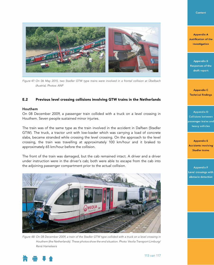
Figure 47: On 06 May 2015, two Stadler GTW type trains were involved in a frontal collision at Übelbach
(Austria). Photos: ANP
E�2 Previous level crossing collisions involving GTW trains in the Netherlands
HouthemOn 08 December 2009, a passenger train collided with a truck on a level crossing in Houthem. Seven people sustained minor injuries.
The train was of the same type as the train involved in the accident in Dalfsen (Stadler GTW). The truck, a tractor unit with lowloader which was carrying a load of concrete slabs, became stranded while crossing the level crossing. On the approach to the level crossing, the train was travelling at approximately 100 km/hour and it braked to approximately 65 km/hour before the collision.
The front of the train was damaged, but the cab remained intact. A driver and a driver under instruction were in the driver’s cab; both were able to escape from the cab into the adjoining passenger compartment prior to the actual collision.
Figure 48: On 08 December 2009, a train of the Stadler GTW type collided with a truck on a level crossing in
Houthem (the Netherlands). These photos show the end situation. Photo: Veolia Transport Limburg/
René Hameleers
113 van 117

RuurloOn 16 July 2014, a passenger train collided with a truck on a level crossing in Ruurlo. Some of the approximately 35 train occupants sustained minor injuries, including the train driver.
The train was of the same type as the train involved in the accident in Dalfsen (Stadler GTW). It was also from the series where the crash frames have weld defects. The truck, a boxbody with trailer, became stranded while crossing the level crossing. The train crashed into the side of the trailer, which was laden. The train’s collision speed was approximately 80 km/hour. The collision totally destroyed the trailer and the front of the train was damaged. The driver’s cab remained intact.
Figure 49: On 16 July 2014, a train of the Stadler GTW type collided with a truck on a level crossing in Ruurlo
(the Netherlands). Photos: Stefan Verkerk
114 van 117

APPENDIX F
LEVEL CROSSINGS WITH OBSTACLE DETECTION
Automatic full barriers with obstacle detectionStarting in 1999, a trial of a new type of level crossing, the automatic full barriers (ADOB), was carried out in the Netherlands. With the automatic full barriers, both sides of the road are closed and automatic obstacle detection checks that the intersection is clear. Originally, the train driver was warned if an obstacle was detected. ProRail has stated that the system was later changed due to numerous false reports: currently, if an obstacle is detected, the exit barrier on the level crossing stayes open. This allows road users to leave the crossing, but it does not help to prevent an accident if the vehicle had stalled.
According to ProRail, experiences with this level crossing were decidedly negative; arguments put forward by ProRail include higher costs, additional waiting time for road traffic, which is precisely what invites risktaking, numerous breakdowns and susceptibility to vandalism or other mischievous behaviour that can disrupt rail traffic. This type of system is currently operating in two locations; ProRail does not envisage any wider use.
Point at which warning is givenBased on a speed of 140 km/hour, the latest point at which the train driver must deploy the emergency brakes to come to a stop before the level crossing is at a point approximately 20 seconds running time before the level crossing. In practice, this is about the same time as when the level crossing barriers start to lower. At this stage, it is in no way unusual for road vehicles on the level crossing to still be in the act of clearing the crossing.
Therefore, obstacle detection will have to take place while the road traffic can still use the level crossing normally. That in turn means that the detection should be sufficiently intelligent to differ between obstacles that are still leaving the level crossing and obstacles that will not be able to do so. Alternative options would be to accept an increased number of false alarms or a longer warning time.
Obstacle detection perfectly feasible, but little time to alert train driverA major inventory of the possibilities for obstacle detection was compiled by the British Rail Safety and Standard Board after an accident in the United Kingdom.57 That research concluded that it was technically feasible and actually quite easy to detect obstacles. Where such systems replaced a manned level crossing (as was done in Germany and Italy), this was cheaper and safer (because a human level crossing guard makes mistakes
57 Rail Safety and Standard Board/Arthur D. Little, Research into obstacle detection at level crossings, report T522, 2006
115 van 117

more often than automatic notification that the crossing is clear does). Obstacle detection was introduced in those countries specifically to save personnel costs at guarded level crossings, not to bring about increased safety at automatic half barrier crossings.
The inventory shows that it is problematic to use obstacle detection at automatic half barrier crossings.58 Level crossings of this type purposely have short warning times and the difficulty lies in alerting the driver and deploying the emergency brakes within the limited time available. It must be noted here that options where emergency braking would automatically be executed by the train were not considered because a suitable, modern automatic train protection system was not widely available in Great Britain at that time. The research was, however, positive about such a link, which has successfully been used at some hundred level crossings in Sweden. The Safety Board believes that this is worthy of consideration for the Netherlands, because this kind of continuously operating system already exists in large parts of the railway network (ATBEG or the future ETCS Level 2).
58 Rail Safety & Standard Board/Arthur D Little, Research into obstacle detection at level crossings, 2006.
116 van 117

117 van 117
DUTCHSAFETY BOARD
Visiting Address Anna van Saksenlaan 50 2593 HT The HagueT +31(0)70 333 70 00 F +31(0)70 333 70 77
Postal Address PO Box 95404 2509 CK The Hague
www.safetyboard.nl