Embed Size (px)
Citation preview

Mini Project
EN407 – Robotics B.Sc. Engineering
University of Moratuwa
COLLISION AVOIDANCE MOBILE ROBOT
By Dangampola D.L. - 020059 De Abrew K.N.T. - 020067 Kasthuriarachchi T.D. - 020203 Malwatta K.A. - 020241
Dahanayake J.K. - 020057
Department of Electronic and Telecommunication Engineering August 2006

EN407 : Robotics Collision Avoidance Mobile robot
i
Abstract
The objective of this project was to develop a Collision Avoidance
Mobile robot with onboard sensors and a Microcontroller. The mobile robot
designed is capable of moving in an environment which has obstacles
avoiding collisions.
The Designed mobiles robot is a three wheeled Robot with
differential steering. The Robot has an onboard rotating Ultrasonic Sensor
and Bumper switches for improved safety. The Main Controller of the Robot
is implemented in a PIC microcontroller.
The Mobile robot uses the Potential Field Method for Obstacle
avoidance. The Algorithms runs on the PIC microcontroller based on the
information received by the Ultrasonic Ranger.

EN407 : Robotics Collision Avoidance Mobile robot
ii
Table of Contents
1.0 Introduction ........................................................................................................................................ 1
1.1 Scope and Overview....................................................................................................................... 1
1.2 Basic Operation .............................................................................................................................. 1
2.0 Overall system Design and operation................................................................................................. 2
2.1 Functional Block Diagram ............................................................................................................. 2
2.2 System Operation ........................................................................................................................... 3
2.3 Implementation of the potential field method ................................................................................ 4
3.0 Components of the Mobile Robot ...................................................................................................... 6
3.1 The PIC 877A microcontroller....................................................................................................... 6
3.2 Servo Motor.................................................................................................................................... 6
3.3 Sonar Sensor................................................................................................................................... 7
3.4 Stepper motors................................................................................................................................ 7
3.5 The PIC 873A microcontroller – Sonar/ Servo controller ............................................................. 9
3.6 Mechanical Design....................................................................................................................... 11
3.7 Circuit Diagram............................................................................................................................ 12
4.0 Results .............................................................................................................................................. 12
5.0 Limitations and Further Developments............................................................................................ 13
APPENDIX A : PIC Program : Main Controller ................................................................................... 14
APPENDIX B : PIC Program : Servo and Sonar Controller ................................................................. 30

EN407 : Robotics Collision Avoidance Mobile robot
iii
List of Figures
Figure 1 : The Mobile Robot.................................................................................................................... 1
Figure 2: Mobile Robot Navigating through Obstacles ........................................................................... 2
Figure 3: Block Diagram of the System................................................................................................... 2
Figure 4 : Flow chart ................................................................................................................................ 3
Figure 5: Sonar Readings ......................................................................................................................... 4
Figure 6 : Repulsive Forces...................................................................................................................... 5
Figure 7 : Local Goals.............................................................................................................................. 5
Figure 8: hitec HS 300 Servo motor and the Sonar sensor ..................................................................... 6
Figure 9 : SRF 05 Sonar Sensor ............................................................................................................... 7
Figure 10 : FDK Stepper motors – Unipolar mode operation.................................................................. 8
Figure 11 : PIC 873A microcontroller Pin Diagram................................................................................ 9
Figure 12 : PIC 873A microcontroller - Used Pin layout ........................................................................ 9
Figure 13 : Robot Base........................................................................................................................... 11
Figure 14 : Circuit Diagram ................................................................................................................... 12

EN407 : Robotics Collision Avoidance Mobile robot
1
1.0 Introduction 1.1 Scope and Overview
The purpose of this project was to develop a mobile robot with the collisions avoidance
capability in an obstructed environment. The mobile robot has been built as a fully autonomous vehicle
with onboard sensors to get information about the surrounding environment.
The mobile robot is a three wheeled robot platform which employs the differential steering
mechanism for motion in given angles. Two stepper motors have been used for the driving wheels. The
robot has an onboard Ultrasonic sensor which is mounted on the standard servo motor. The Servo
Motor and the Ultrasonic sensor are controlled by a dedicated microcontroller which sends the
information collected to the main controller. To improve the reliability the bumper switches has been
used as redundant sensors.
The Potential Field method has been used as the obstacle avoidance algorithm and the
Algorithm is implemented in the main PIC microcontroller which is on the mobile robot. The
Algorithm implemented is used to avoid the obstacle and to drive the robot to a locally generated goal.
Figure 1 : The Mobile Robot
1.2 Basic Operation When the robot is switched on it scans its surrounding environment by rotation the Ultrasonic
sensor in 45o steps. Then the distance of the nearest obstacle in each direction will be measured and the
data is fed to the main controller. The main controller implements the Potential Field Algorithm and
decides the direction which the mobile robots should move. According to that, the main controller
sends the control signal sequence to each stepper motor to turn the robot to the specified angle using
differential steering.

EN407 : Robotics Collision Avoidance Mobile robot
2
Thereafter the robot moves a predefined distance and the robot scans its environment again as
mentioned earlier. This process continues when the mobile robot is switched on.
Figure 2: Mobile Robot Navigating through Obstacles
2.0 Overall system Design and operation
2.1 Functional Block Diagram
Figure 3: Block Diagram of the System
The above diagram is the functional block diagram of the entire system. The Main Controller
will trigger the Servo Controller, receive the distance values, run the collision avoidance algorithm and
control the Stepper motors. The Servo Controller controls the sonar sensor and servo motor while
providing the readings from the sonar sensor to the Main Controller. A description of each of these
functional blocks is given in next chapter.

EN407 : Robotics Collision Avoidance Mobile robot
3
2.2 System Operation
The operation of the whole system can be represented using the following flow chart.
Figure 4 : Flow chart

EN407 : Robotics Collision Avoidance Mobile robot
4
Figure (b)
2.3 Implementation of the potential field method
Here we implement the conventional potential field method with some modifications so that it
is not computationally expensive in the PIC microcontroller. Here we do not use the inverse square
law to calculate the repulsive force exerted by the obstacles because it involves very expensive
calculations that takes lot of time in a microcontroller. Instead we use weights so that obstacles that are
nearer to the robot exert high weights while obstacles that are far from the robot exert low weights.
These weights are equivalent to the repulsive forces.
The distances to the obstacles are given by the sonar sensor readings. These readings come
from angles 0, 45, 90, 135 and 180 degrees as shown in the figure (a). There’s an assumption that we
make at this point. When we get a reading from a certain direction we assume that the obstacle is
aligned with that axis. For example the obstacle A will give a reading in 0 degrees direction so we
assume that A is aligned with 0 degrees axis in calculating the repulsive force though it is not the real
case. We make this assumption because it is hard to calculate the exact angel at which the obstacle is
located using a PIC microcontroller. For the sonar sensor the probability of finding an object is
distributed as shown in figure (b). This is a bell-shaped probability distribution having the highest
probability along the main axis of the sonar beam. Therefore we think that our assumption is
reasonable enough to apply.
Figure 5: Sonar Readings
Robot 0
4590
135
180
Obstacle A
Figure (a)

EN407 : Robotics Collision Avoidance Mobile robot
5
When we calculate the resultant force we ignore the obstacles that are beyond a certain
threshold distance DTh to avoid unnecessary calculations. For example obstacle B is taken into account
because it is within the threshold while obstacle A is discarded from the process of calculating the
resultant force as it is away from the threshold distance.
Figure 6 : Repulsive Forces The repulsive force (or weight) for obstacle B is calculated as F = DTh – D1 If all five sonar readings come from within the threshold distance, the repulsive force is not calculated
and the robot is instructed to reverse.
All the repulsive forces are resolved and the total repulsive forces’ x and y components are calculated.
Resolving for 45 and 135 degrees components is done using a table lookup. The advantage of these
angles is that we don’t have to use two separate tables for sin and cos.
Selecting the goal is done on a priority basis. This priority scheme is shown in the following figure.
Figure 7 : Local Goals
DTh
D1
D2
Robot
Obstacle A
Obstacle B
180 Priority level = 3
Robot
45 Priority level = 2
0 Priority level = 3
135 Priority level = 2
90 Priority level = 1

EN407 : Robotics Collision Avoidance Mobile robot
6
For example if the sonar reading indicates that the 90 direction is clear (that is there’s no
obstacle within the threshold distance in that direction) it is the direction that is chosen as the goal
direction even if any other directions are clear.
After assigning the goal, its attractive force which is a constant is resolved if necessary and is
subtracted or added accordingly to the resultant repulsive forces’ x and y components to calculate the x
and y components of the total force acting on the robot. Then the angle of the resultant force is
calculated from these x and y components and it is fed to the motor controlling unit.
3.0 Components of the Mobile Robot
3.1 The PIC 877A microcontroller
This is the main controller of the mobile robot. When the robot is turned on, the main controller
PIC sends a trigger to the servo control PIC to perform an obstacle scan. The results of the obstacle
scan are then obtained by the main controller PIC through USART reception. Once the data is
received, it is inputted into the conventional potential field algorithm as described earlier. This
algorithm will decide the angle to which the mobile robot should turn. Then the appropriate control
signals are sent to the two stepper motors in order to obtain this angle. Afterwards the control signals
required for the movement (forward or backward) is give to the stepper motors which will be followed
by stopping the mobile robot and sending the trigger signal to the servo control PIC. This will continue
as a cycle.
3.2 Servo Motor The Servo motor is used to rotate the sonar sensor to 5 predetermined positions. At these positions the
reading of the sonar sensor is obtained 4 times and averaged.
Figure 8: hitec HS 300 Servo motor and the Sonar sensor
The servo motor consists of three wires.
Yellow wire - Control

EN407 : Robotics Collision Avoidance Mobile robot
7
Red wire - +5 V
Black wire - Ground
The position of the servo motor is determined by the width of the (3-5V) pk-pk square pulse
sent to its Control wire. The pulses should be given every 20 ms. Given below are the pulse durations
required for the servo motor positions are given below.
• Center Position – 1.7 ms
• 90 degrees counter clockwise from center position – 0.9 ms
• 45 degrees counter clockwise from center position – 1.3 ms
• 90 degrees clockwise from center position – 2.1 ms
• 45 degrees clockwise from center position - 2.5 ms
3.3 Sonar Sensor
Figure 9 : SRF 05 Sonar Sensor
The mode pin is not used , thus we have used separate pins for echo output and trigger input.
The sonar sensor is triggered by sending a 10us pulse. The echo pulse width determines the distance
to the object. The range of the echo pulse is from 100us to 25 ms.
The 10 us is sent to the trigger input and the echo output is received by the PIC 873A
microcontroller.
3.4 Stepper motors
Two FDK stepper motors are used and are controlled independently of each other to obtain the
differential steering of the mobile robot. The step angle of the stepper motor is 7.5 degrees. 2 wires
(red) are present to give power and the other 4 wires ( black, brown, yellow and orange) are for
controlling the motor.

EN407 : Robotics Collision Avoidance Mobile robot
8
Drive mode – Unipolar mode
Excitation - Two way excitation
Two way Excitation
Figure 10 : FDK Stepper motors – Unipolar mode operation

EN407 : Robotics Collision Avoidance Mobile robot
9
3.5 The PIC 873A microcontroller – Sonar/ Servo controller
Figure 11 : PIC 873A microcontroller Pin Diagram
In the above PIC microcontroller the following pins are configured as inputs and outputs
Inputs
RA1 - Echo output from sonar
RB0 – Interrupt from Master PIC
Outputs
RA3 - Trigger input to the Sonar
RC0 -PWM output to the Servo Motor
RC6 -USART TX to the Master PIC
Figure 12 : PIC 873A microcontroller - Used Pin layout

EN407 : Robotics Collision Avoidance Mobile robot
10
When an interrupt arrives from the Master PIC to perform obstacle surveillance, the PWM
output will be given such that the servo motor will move the sonar sensor to Position 1. At this

EN407 : Robotics Collision Avoidance Mobile robot
11
position the sonar will be triggered and four echo outputs will be obtained and averaged. Then the
servo motor will move the sonar to Position 2 and as before the readings from the sonar sensor will be
obtained and averaged. This procedure is performed in 5 positions. Finally the averaged distance
readings from these 5 positions will be sent through USART transmission to the master PIC. The
software flow chart of the PIC program is given below. The program is given in Appendix B .
The 5 Position that readings from the sonar sensor are taken
Position 1 – 90 degrees counter clockwise from the center position
Position 2 - 45 degrees counter clockwise from center position
Position 3 – Center position
Position 4 - 45 degrees clockwise from center position
Position 5 - 90 degrees clockwise from center position
3.6 Mechanical Design
The mobile robot has a circular shape of 10cm radius. The circular shape chosen to suit the
differential steering mechanism and to minimize the collisions when steering. The robot consists of
two driving wheels and one passive wheel.
The robot base is basically constructed using plastics. The two motors are mounted to the base
using metal sheets. The wheels are directly coupled to the motor shafts and the wheels were cut from
Nylon.
Figure 13 : Robot Base

EN407 : Robotics Collision Avoidance Mobile robot
12
3.7 Circuit Diagram The Circuit Diagram of the Electronic circuit of the robot is shown below.
Figure 14 : Circuit Diagram
4.0 Results
After creating the mobile robot, implementing the collision avoidance algorithm on the
microcontroller, testing and with modifications we were able to achieve our project goal. That is to
design a collision avoidance robot. Our final version of the mobile robot was able to avoid collisions

EN407 : Robotics Collision Avoidance Mobile robot
13
90% of the time (according to test results). Since it is quite difficult to develop a 100% collision
avoidance system, we believe that the achieved collision avoidance rate is satisfactory.
5.0 Limitations and Further Developments
There are several limitations that exist in the current system which should be addressed in
further developments.
The mobile robot has information only about its local environment and does not localize itself
in a global environment. Thus it is impossible to introduce a define goal to the mobile robot to reach in
global environment.
The robot scans through the sonar sensor only in five predefined directions. Thus it is assumed
that any obstacle detected lies in those directions only. This effect can be minimized by incorporating
probabilistic models to the system which is somewhat difficult in a microcontroller.
Also sometimes some obstacles are not detected when the obstacle surface isn’t in an angle to
sufficiently reflect the waves sent by the sonar sensor.
A proper attention should be paid to the above matters in a further development of this project.

EN407 : Robotics Collision Avoidance Mobile robot
14
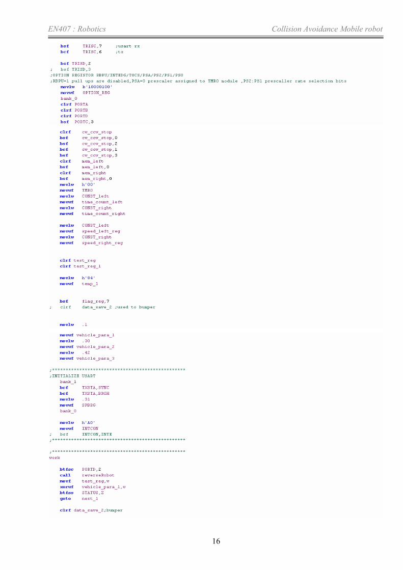
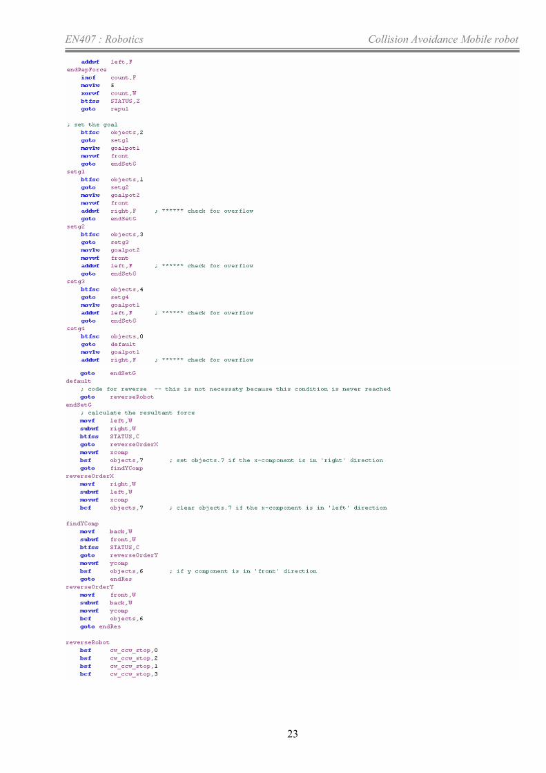
APPENDIX A : PIC Program : Main Controller (The Editable .asm files are given in the CD)

EN407 : Robotics Collision Avoidance Mobile robot
15
EN407 : Robotics Collision Avoidance Mobile robot
16

EN407 : Robotics Collision Avoidance Mobile robot
17

EN407 : Robotics Collision Avoidance Mobile robot
18

EN407 : Robotics Collision Avoidance Mobile robot
19

EN407 : Robotics Collision Avoidance Mobile robot
20

EN407 : Robotics Collision Avoidance Mobile robot
21

EN407 : Robotics Collision Avoidance Mobile robot
22
EN407 : Robotics Collision Avoidance Mobile robot
23

EN407 : Robotics Collision Avoidance Mobile robot
24

EN407 : Robotics Collision Avoidance Mobile robot
25

EN407 : Robotics Collision Avoidance Mobile robot
26

EN407 : Robotics Collision Avoidance Mobile robot
27

EN407 : Robotics Collision Avoidance Mobile robot
28

EN407 : Robotics Collision Avoidance Mobile robot
29

EN407 : Robotics Collision Avoidance Mobile robot
30
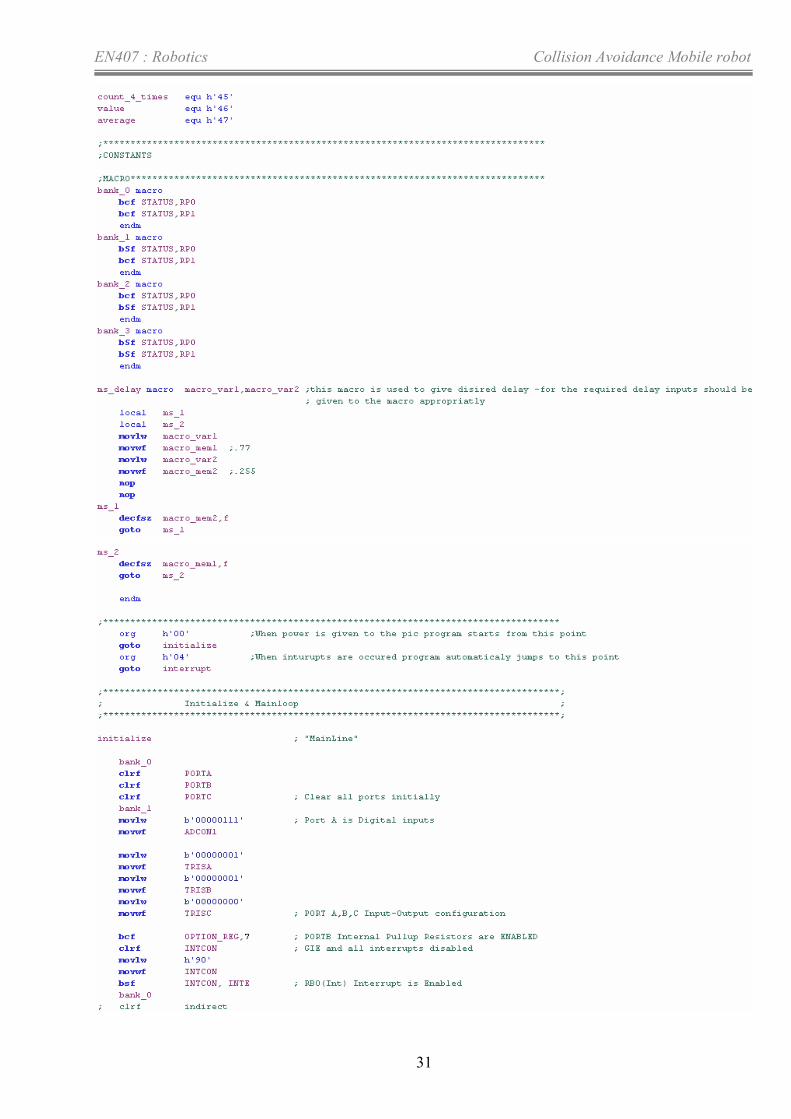
APPENDIX B : PIC Program : Servo and Sonar Controller
EN407 : Robotics Collision Avoidance Mobile robot
31

EN407 : Robotics Collision Avoidance Mobile robot
32

EN407 : Robotics Collision Avoidance Mobile robot
33

EN407 : Robotics Collision Avoidance Mobile robot
34

EN407 : Robotics Collision Avoidance Mobile robot
35

EN407 : Robotics Collision Avoidance Mobile robot
36


![15-TCAS.ppt [Sólo lectura] · •The onboard Traffic Collision Avoidance System (TCAS) was developed to prevent mid-air collision, particularly in case Air Traffic Controller guidance](https://img.pdfslide.us/doc/110x75/5ec9cc7838f1360b29432e4e/15-tcasppt-slo-lectura-athe-onboard-traffic-collision-avoidance-system-tcas.jpg)