Embed Size (px)
Citation preview
COLLIDING LINACS
llgo Amaldi CERN, Geneva, Switzerland
Summary
The radius and the cost of electron-positron colliding rings increase as the square of the· beam energy, so that it is generally felt that new approaches are needed for reaching energies definitely larger than the ones attainable with LEP. This article reviews the schemes that have been proposed. They are all based on the use of linear accelerators so that, before describing them, we write down the general conditions that a few beam parameters have to satisfy in order to reach the wanted luminosity at any given energy. The presentation of the various proposed schemes is as complete as possible; but it is in the nature of a futuristic subject, and we can only list the technological problems that have to be solved in the next decade before electron-positron colliding linacs become the reliable tools that storage rings are nowadays.
1. Introduction
The scaling laws of the parameters and cost of e•e- colliding rings were derived some years ago by Richter 1
, and the LEP design study proves that machines of this type can extend the presently available energy range up to about 200 GeV in the centre of mass 2
'3
•
These energies can be obtained with copper cavities by dissipating p:::Mers of the order of 200 ?M'. With superconducting cavities LEP will reach (2 x 130) GeV without increasing the total ~2 ,~. Cost optimizations of storage rings with conventional or, alternatively, superconducting cavities have been made by Ritson and Tigner 5 and by Bauer~. The conclusion is that, for a machine with superconducting cavities (SC), the optimwn cost C scales roughly as the square of the berun energy E,
(I)
as for conventional cavities lCC) 1 , but the constant k is about two times smaller. Lin Eq. (1) C0 is the cost of the installations that are energy independent, such as the injector and the experimental areas.] Ritson and Tigner gave low and high values for the constant k for a cavity frequency of 1500 MHz 6
:
(0.10-0.13) M$/GeV'
• (0.045-0.065) M$/GeV'
(2)
(3)
It is generally believed that in about 10 years time, superconducting cavities of the required characteristics will be mass produced and will work with high reliability. TI-ie above argwnents show that these technological advance~ will be useful for obtaining more energy within a fixed budget, but will not influence the cost scaling law'of Eq. (1), which is detennincd by the well-known dependence of the energy loss per turn by synchrotron radiation U on the beam energy E and the radius of curvature p: U ~ E~/o.
I have been invited to review the status of the various proposals that have been· put forward to substitute Eq. (1) by a linear dependence of cost upon energy. This invitation has been extended to me, I presume, because of a short article written about four years ago proposing the use of two superconducting linacs to obtain energies larger than 300 GeV in the centre of mass, with a collider having no radiation problem and thus with a cost proportional to the energy 7
• This
kind of accelerator, in whi~h the berun energy is recovered by the opposite linac was proposeda, as a possible basis for a world-wid~ enteIJ>rise, at the International Study Group on Future Accelerators and HighEnergy Physics held at Serpukhov in May 1976 9
• The idea was discussed in various laboratories, and in the following months I was infonned that similar schemes had already been proposed ir1 the past. In the rest of this Introduction I shall present a sketch of the developments in this field in chronological order as they are now known to me.
Superconducting colliding linacs firing one into the other were proposed in 1965 by Tigner 10 • At such an early stage of development of the storage ring technique, the energies aimed at were low (O.S and 3 GeV) and only electron-electron ~ollisions were considered. Synchrotron radiation was not yet a problem for e+erings and, since the linac scheme offers no other advantage, it was too easily forgotten. In March 1971, at the American Accelerator Conference, ideas on upgrading the SLAC accelerator were presented11 , the main one being the recirculation of the.electron beam in the linac to increase the energy for fixed-target physics. Also considered was the possibility of accelerating two intense electron bunches in the same SLAC pulse, so that they could collide at one point after having been deflected in the two branches of one of the two recirculator loops 12
• At Novosibirsk, conventional and superconducting linacs were considered, in the same years, as tools for reaching the hundred GeV region by G.I. Budker, A.N. Skrinsky and collaborators. In 1971, at the Merges seminar, Skrinsky spoke briefly about these ideas and also about the possible use of storage rings for muonsi 3
• Electron-electron collisions at (2.5+2.5) GeV were also mentioned by Saranzev in a Dubna report which concerns the constniction of a collective linear accelerator for protons and deuterons 1 ~. These various suggestions contained the genns of the present developments but unfortunately did not attract the attention of the high-energy physics co1JJJ1unitr until the publication, in 1976, of my short article and its presentation at the Serpukhov meeting 8
• At CERN, at the begirming of 1976, Lengeler looked into the technical problans connected with the realization of a 2 x x 100 GeV superconducting linac and made a realistic cost estimate 15
• By comparing these costs with the optimized costs of electron-positron storage rings as derived by Richter 1
, it was concluded at the Moriond meeting in February 1976 that, costwise, a collider based on superconducting linacs would be advantageous with respect to a storage ring for energies of the order of 2 x 150 GeV, only if accelerating fields of the order of 10 ~1\1/m could be obtained 16 ,
In recent years conventional linacs have attracted increasing attention. Voss laid down a parameter list for a 2 x 100 GeV collider17
, and the Novosibirsk group considered the main technical problems to be solved if colliders of this type are to be realized, and proposed original solutions for some of them 18
• Almost every one who is interested in colliding linacs was present at the First ICFA Workshop held at Fennilab in October 1978. The working group on electron-positron colliders~ chaired by J. Rees, was thus an active fon.1m for comparing ideas developed independently in various laboratories, and many of the points I shall discuss in the followin,g were clarified in the final report issued by this group 1 s. TI-iey were also slDTl!Tlarized and complemen-ted in the concluding talk given by Richter at the
-314-
San Francisco Particle Accelerator Conference in March 1979 20
ln 1979 this field saw two interesting developments. Gerke and Steffen proposed an improved version of the scheme with energy recovery 21 , while a new scheme started to be studied at Stanford22 . This latter idea is to use the SL.AC linac to accelerate positron and electron bunches simultaneously; these bunches would eventually collide in a special ring after only half a turn.
The rest of the article is devoted to a derivation of the simple equations that relate the main parameters of a collider based on linacs, and then to a discussion of the possibilities and the limitations of the proposed schemes. For completeness in the presentation I shall also quote the main results obtained by the electronpositron working group of the Second ICFA Workshop, held at Les Diablerets in October 1979 23
2. Basic Equations
Let us consider two streams of colliding bunches, each containing N particles, crossing in the interaction point at the frequency f with energy E = ymc 2• The lwninosity is given by the simple relation
fN2
L = --4no2 (4)
where a is the r.m.s. radius of each bunch; for the moment these bunches are asswned to have circular crosssection. The bLmch radius has the fonn
( 5)
where £ = no 6p/mc is the nonnalized emittance at 1 r.m.s., and 8 is the amplitude function at the interaction point.
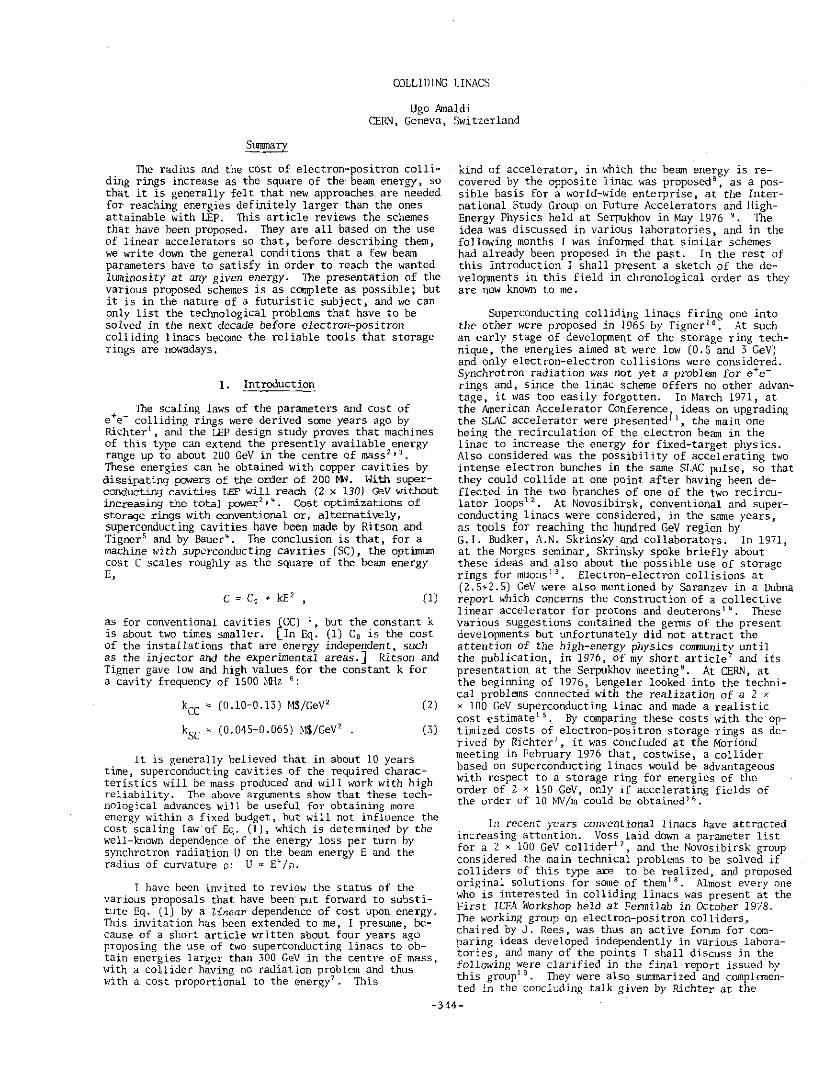
The luminosity cannot be arbitrarily increased by decreasing E and S, because of the consequent strong effects of one bunch on the other. With reference to Fig. 1, we consider a particle incident on an opposite bunch at a typical distance a from the axis. The bunch acts as a focusing lens so that the particle is deflected towards the axis and emits synchrotron radiation, which at the ICFA Workshop was dubbed "beamstrahlung". Two para~eters have been introduced to quantify these effects 13
'20 :
disruption parameter D redN
2ya2
b t al 1 , __ 2 3 yN2 •
earns r 1 ung parameter: u 3 re dc 2 ,
(6)
(7)
where re is the electron classical radius. If D << 1, the disruption parameter equals the relative migration ~r/r of the typical particle towards the axis (Fig. 1). For D >> 1 the particles oscillate around the axis during the collision, and the phenomenon becomes very complicated. Pinch effects are expected to play a role and, for large enough value of D, the bunches will blow up. Calculations of the maximwn allowed value for D have been made at Novosibirsk' 0
• 2 4 and are under way at
SLAC25 • According to the Novosibirsk group, D can be as large as 20-30 without any adverse effect, while at the First ICFA Workshop D '' 1 was taken as a conservative maximum. At the Second Workshop, by applying an approach recently developed in the field of storage rings, Pellegrini and Tigner came to the conclusion that D cannot be larger than a few units 26 . Clearly, both calculations and experimental data are needed in
' d ' ~~ ' '
TYPICAL INCIDENT--.---t-=.:: PARTICLE
Fig. 1 Schematic representation of the effects of a moving bunch on a typical particle of the opposite bunch.
order to resolve this very important issue. It has also to be noted that the "disruption parameter" is proportional to the familiar quantity 6Q, the incoherent beambearn tune shift so widely discussed in connection with electron-positron storage rings:
D (8)
The introduction of a new quantity could thus be avoided. However, I think that since 6Q has by now a very clear place in the theory of storage rings, it is better to use a different parameter in discussing colliding linacs.
In storage rings the lLOTiinosity is limited by the maximLDTI 6Q value according to the relation 3
L(on- 2 s- 1) "' 1. 23 :-..: 10 3 3 P(MW) .o(m) 6Q (storage rings) , £ 3 (GeV) S(m)
(9)
where .o is the bending radius and P is the power of both stored beams. For an optimized machine with conventional cavities p(m) "'0.5 E2(GeV2), so that Eq. (9) becomes
L(cm- 2 s- 1) "' 6.2 x 10 32 E(Jem(m] 6Q (storage rings) .
(10)
For a colliding linac scheme, by introducing Eq. (6) into Eq. (4) we obtain
L(an- 2 s-')~3.5xl0" ~:i D (colliding linacs), (11)
so that the luminosity depends on the beam power but not on the beam energy. In a storage ring the beam power must scale linearly with E to maintain the luminosity constant, while the cavity losses and the power cost increase as E2
• In the linac scheme the beam power can be kept constant, and the cavity losses and the power cost depend only linearly upon the beam energy.
When D is small the beamstrahlung parameter of Eq. (7) equals the fractional energy lost by the particle in radiation. Since the beamstrahlung introduce~ an enerv,y spread, 6 must always be smaller than 1. Fonnally O can be expressed as a function of E and L:
6 "" 8nr~ EL "'0.37 E(GeV) L(lQ32 on-2 s-1) 3mc 3 fc! f (Hz) d (rrun)
(12)
Once E is fixed and d, P, and D have been chosen to give the desired lwninosity [Eq. (11}], the beamstrahlung process imposes through C a lower limit on the bunch frequency f. It is necessa'!1 to stress that the number of radiated photons is small 9 , so that one must worry not only about the average loss but also about the fluctuations during the radiation process.
-3i5-
If the crossing bunches have elliptical section, the above equations have to be modified. By introducing the ratio between the two transverse dimensions
R oma:x
> 1 (13) --.- . min 0
the modifying factors can be read in Table 1 " Table 1 ----
Modifying factors to take i~to account the bunch shape (crmax. 0m1n ~ 02)
quantity Equation Multiplicative factor
D 6 2R/(R+l) > 1
a 7 4R/ (R+ 1)' ' 1
L 4 1
The table shows that, if it would be pos!?ible to make R >> 1 while keeping the product omax.offi1n constant, the lwninosity would not be inflL:enced, while the beamstrahlung parameter could be substantially reduced.
3. Superconducting Linacs with Energy Recovery
The collider that uses superconducting linacs and recovers the energy of the used bunches was chronologically the first to be proposed 1 a and was named peLoron1
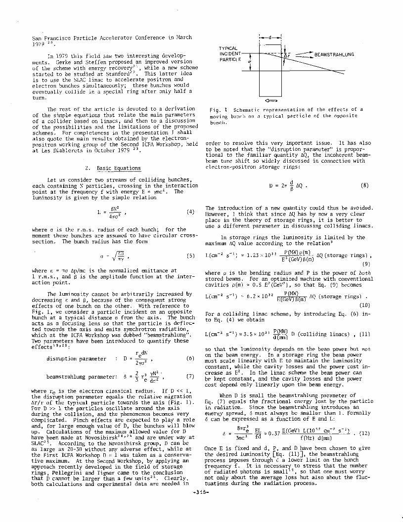
which in Greek means "large and prodigeous being" but can also be read as: Positron and Electron Linear Oscillator Radiating Only Negligibly. The working principle of a peloron is best illustrated by first supposing that one can easily produce electron and positron beams of very small emittance [Fig. z].
Fig. 2 Working principle of colliding linacs with recovery of the beam energy. For simplicity, in this drawing it is supposed that electron and positron bunches can be directly produced from an injector with small emittances.
1he collinear, superconducting linacs accelerate two beams, and magnetic lenses focus then to very small transverse dimensions in one or more low-8 interaction regions. After crossing, the bunches give their energy back to the electromagnetic field of the opposite 1inac, since there they find an electric: field having opposite phase to decelerate them. Stationary conditions are achieved, and in each linac the energy given back to the electromagnetic field is used to accelerate the beam, which moves in the opposite direction. The beams are dumped at the end of the "uphill" path when very little energy is left, so that the power consumption will mainly be contributed by the losses of the cryogenic system and by the cavity losses (which include the very important ''higher-order mode" losses, to be discussed later).
the linac, the bunch frequency f cannot be arbitrarily large:
f s (Zn+l) c~~ (14)
where V is the voltage per unit length and n is the number of noints in which the bunches cross in each linac. On the ~thcr hand, by requiring that the energy spread at the crossing point is small, through Eq. (12), the beamstrahlllilg process poses a lower limit on the frequency. The two conditions are very restrictive and in practice fix the frequency. For instance, with E = ""250 GeV, V= 10 MV/m, d = 5 mm, and L = 10 33 on- 2 s- 1
,
the choice n ~ 2 and 6 s l x 10- 2 implies f = 2.5 x 10" Hz. Then, for a given value of D, Eq. (11) fixes N and Eq. (4) detennines o. In the example, with D = 1 one obtains N = 7.2 x 10 1 a and a= 1 µm. Even by choosinp, a small value of Sat the interaction point (S ~ 5 an), the required nonnalized emittance turns out to be E = io-s 1TITI, about a factor of 3 smaller than the one measured at SLAC with N,;;: 10 9 22 .
Since the energy of the bunches has to be recovered, the beam-beam interaction should not cause a too large increase of the emittance. For D < l, the emittance due to the collision is -
a 2 DY c*" z, --;r- = nreN (15)
and is simply proportional to the number of particles per bunch. In the example, £* comes out to be 20 times larger than e, but is still small enough to be in the acceptance of the opposite linac. However, the same emittance growth would take place at each bunch crossing in the linacs and, since this is unacceptable, the bunches have to be spatially separated in the Zn unwanted crossings by means of suitable combinations of electric and magnetic fields. (For this reason, n cannot be too large.) By the same token, after the collision the bunches cannot be refocused in another interaction region, so that in all schemes in which N ~ t/nr the experiments have to be served by time-sharing. e
At SLAC, positron emittances are at present 10 t~nes larger than electron emittances, so that the reduction of electron cmittances and the production of positron bunches of much smaller emittances than arc now available are the main problems to be solved in order to build electron-positron colliding linacs of reasonably high llDTiinosities. These problems arc conunon to all schemes, both with and without energy recovery. A problem that, instead, is special to the peloron is the need to have very efficient energy recovery in the braking linac. I will now discuss these two subjects in turn.
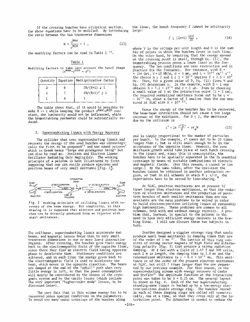
Steffen designed a wiggler storage ring that would produce small beam emittances in damping times that are of the order of l ms 27
• The lattice of this ring consists of strong sector magnets of high field and alteniating polarity (Fig. 3) that produce a strong radiation damping. At 1 GeV with a field of 1.67 T and 300 cells, each 1 min length, the damping time is 1.8 ms and the renonnalized emittance is c ~ 6.4 x 10- 5 nm. lbis emittance is of the order of the present electron emittances at SLAC, but still 7 times larger than the one requested by our previous example, For this reason, in the superconducting scheme with energy recovery of Gerke and Steffen21 the amplitude function at the interaction point was taken to be S = 0.25 on. The general layout is shown in Fig. 4. Each of the two superconducting standing-wave linacs is backed up by a low-energy elec-tron-positron double storage ring. The bunches stored
1be very fact that recovered poses special To avoid too many undue
in this scheme energy has to be in each of these damping rings are called off symmetri-conditions on the parameters. cally, one at a time, so that they cross only at the in-crossings of the bunches along teraction point. The debuncher is needed to reduce the
-316-
energy spread of the· decelerated bunches so that they fit into the energy acceptance of the damping rings. The debunchcrs are traversed in opposite directions by the bw1ches coming from the storage rings, in such a way as to reduce the length of the bunches before injection into the linac.
' ' w
I
I
I I
' I
4 ' '
Fig. 3 One cell of the 1 GeV Wiggler storage ring proposed by Steffen to cool electron and positron bunches {Ref. 27). The angles are~= 0.25 and~= 0.27, and the number of 1 m long cells is 300.
[1..>MPING RING 1Del 8UNCH£R
1cev /r---1 UNAC 1-100 G•V ~INAC •OC - GeV
ID•l 8\JNCHE DAMPING RING 1 Gev
Fig. 4 The superconducting linacs of Gerke and Steffen use two superimposed damping rings at each end to cool the slowed-down electron and the positron bunches before re-use {Ref. 21).
It has to be noted that Gerke and Steffen were the first to propose a recovery scheme with such a low frequency that there are no unwanted crossings. 1be field gradient was asswned to be 20 MV/m at 3 GHz, so that with a bunch frequency f "" 3 x 10" Hz and E = 100 GeV there .is only one bunch in each linac at any time and no unwanted crossings (n = 0). Since each bunch must spend about 2 ms in the cooling ring, 30 positron and 30 electron bunches are stored in the double rings at the input of the two linacs. The other parameters are N = 6 x x 10 10 and o = 0.9 irrn, so that the instantaneous luminosity is 10 33 on- 2 s- 1
• With the asswned Q-value of the cavities (2 x 10 9
), owing to the high gradient the radiofrequency losses at heliwn temperature are so large that the authors propose to n.m the collider at a duty cycle equal to 1/30, with a corresponding reduction in average luminosityz 1.
This last point brings me to the problems of superconductin.g RF cavities. They have been reviewed by Tigner at the First ICFA Workshop 28 and vel)' recently by Picasso in the framework of the European progrrun for phase two of LEP 29
• At present in Europe a large program is under way to develop the relatively low frequency (350 ~~lz) superconducting cavities needed to reach (130 + 130) GeV with LEP. This concrete need will certainly speed up progress, but extrapolations are particularly difficult in this field and I shall limit myself to mentioning the main issues relevant to superconducting linacs.
i) Fundamental parameters are the attainable accelerating gradient V and the Q-value of the cavities. The first detennines the length of the linac, and the two together determine the power that has to be spent to maintain the field. According to Tigner 28
, well-constructed niobiwn cavities can at present reach accelerating fields and Q-values that, for frequencies larger than l.S GHz, are represented by the empirical relations
Y(MV/m) c 2v(lO' Hz) ; Q(lO') x v[lO' Hz) ~ 9 (16)
Higher fields and higher Q-values, by factors of at least 3, are needed to make superconducting linacs worth considering as electron-positron colliders. No fundamental principle is known today that forbids this development, in particular if l"Jb 3Sn cavities are used.
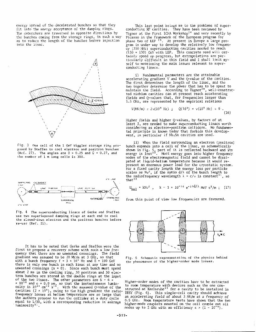
ii) When the field surroµnding an electron (positron) bunch expands into a cell of the linac 1 as schematically shown in Fig. S part of it is reflected backward and its energy is lost 3 ~. Most energy goes into higher frequency modes of the electromagnetic field and cannot be dissipated at liquid-helium temperature because it would represent an enonnous power load for the cryostatic system. For a fixed cavity length the energy loss per particle scales as Nv 2
, if the ratio d/A of the bunch length to the radiofrequency wavelength A~ c/v is constant 31
, so that 32
Uhm! = kNv 2 , k
from this point of view low frequencies are favoured.
_,
Fig. 5 Schematic representation of the physics behind the phenomenon of the higher-order mode losses.
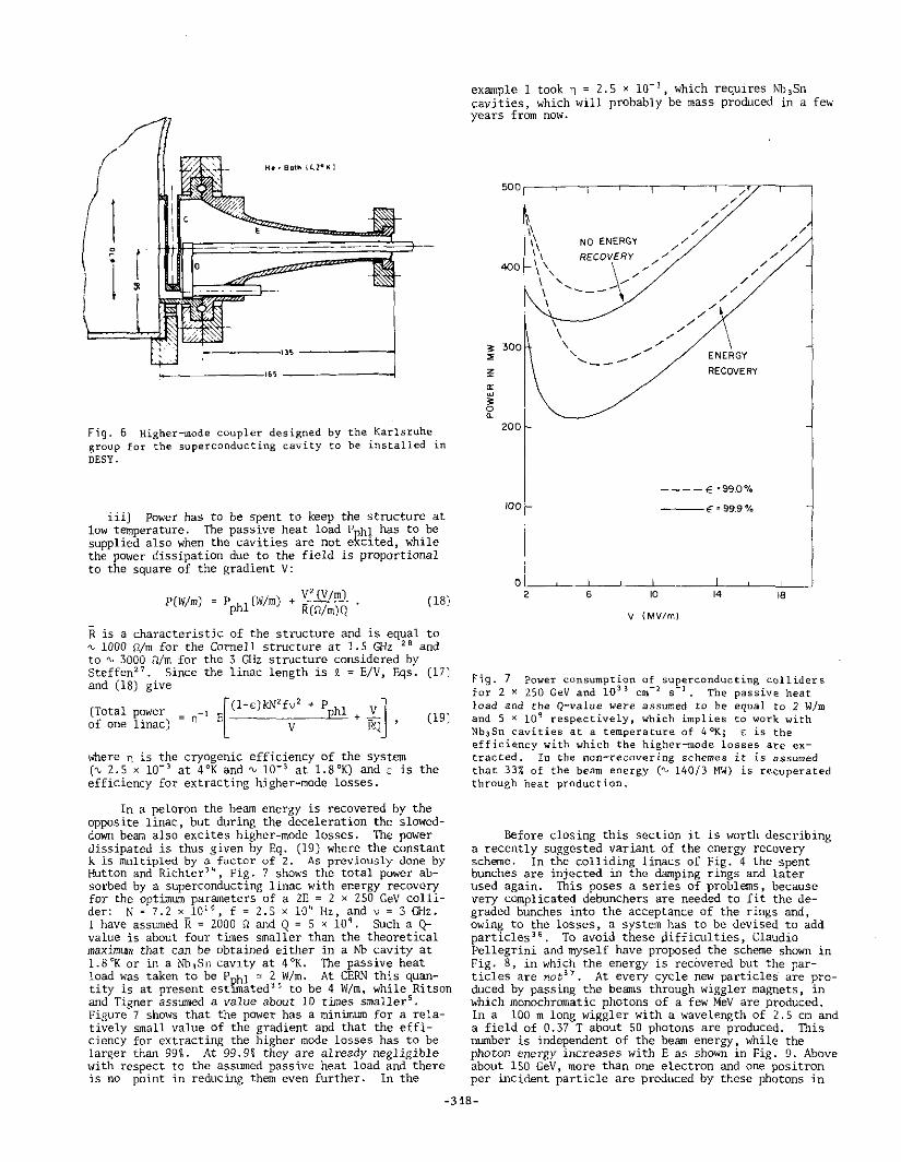
Higher-order modes of the cavities have to be extracted to room temperature with devices such as the one constructed at Karlsruhe 33 for a cavity to be installed in DESY (Fig. 6). 1bis single-cell cavi~y should achieve an accelerating field of about 3 ~1\1/m at a frequency of 0.5 GHz. Room temperature tests have shown that the two higher-mode couplers mounted on the cell couple out all modes up to 2 GHz with an efficiency £ > (1 - 10-lf),
-317-
r '
Fig. 6 Higher-mode coupler designed by the Karlsruhe group for the superconducting cavity to be installed in DESY.
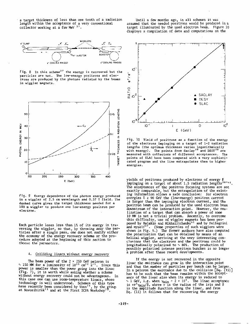
iii) Power has to be spent to keep the st11Jcture at low temperature. The passive heat load Pphl has to be supplied also when the cavities are not excited, while the power dissipation due to the field is proportional to the square of the gradient V:
P(W/m) = P (W/m) + V' (V /m) phl R(n/m)Q ·
( 18)
R is a characteristic of the structure and is equal to '\, 1000 Q/m for the Cornell structure at 1.5 GHz 26 and to '\, 3000 !1/m for the 3 GHz structure considered by Steffen27
• Since the linac length is t = E/V, Eqs. (17) and (18) give
(Total power = - 1 E hl + :!.__ [
(l-c)kN2fv
2 + P -J
of one linac) n v P.Q ' (19)
where n is the cryogenic efficiency of the system ('\. z.s x io- 3 at 4°K and~ io- 3 at l.8°K) ands is the efficiency for extracting higher-mode losses.
In a peloron the beam energy is recovered by the opposite linac, but during the deceleration the sloweddown beam also excites higher-mode losses. The power dissipated is thus given by Eq. (19) where the constant k is multipled by a factor of 2. As previously done by Hutton and Richter 3
". Fig. 7 shows the total power absorbed by a superconducting linac with energy recovery for the optimum parameters of a 2E = 2 x 250 GeV collider: N = 7.2 x 10¹⁰ , f = 2.5 x 10" Hz, and~: 3 Qiz. I have assumed R = 2000 n and Q = 5 x 10 9
• Such a Qvalue is about four times smaller than the theoretical maximlml that can be obtained either in a Nb cavity at 1.8°K or in a Nb 3Sn cavity at 4°K. The passive heat load was taken to be Puhl ~ 2 W/m. At CERN this quantity is at present est1mated 35 to be 4 W/m, while Ritson and Tigner assumed a value about 10 times sma11er 5
•
Figure 7 shows that the power has a minimum for a relatively small value of the gradient and that the efficiency for extracting the higher mode losses has to be larger than 99i. At 99.9% they are already negligible with respect to the assumed passive heat load and there is no point in reducing them even further. In the
example I took n = 2.5 x 10- 3, which requires Nb 3Sn
cavities, which will probably be mass produced in a few years from now.
" :>
'l'
"' w
" 0 ~
soo~---~-~-~-~~-.---/~~--.-~
/ /
~ // ~ / 1\ NO ENERGY / /
\',' RECOV\:y,// / \ , _____ ..... , \
<00
ENERGY
RECOVERY
200
----E :99.0°/o
100 ---€:99.9%
V ( MV/m)
Fig. 7 Power consumption of superconducting colliders for 2 x 250 GeV and 10 33 cm-~ s-1 . The passive heat load and the Q-value were assumed to be equal to 2 W/m and 5 x 10 9 respectively, which implie$ to work with Nb 3Sn cavities at a temperature of 4°K; s is the efficiency with which the higher-mode losses are extracted. In the non-recovering schemes it is assumed that 33% of the beam energy (~ 140/3 MW) is recuperated through heat production.
Before closing this section it is worth describing a recently suggested variant of the energy recovery scheme. In the colliding linacs of Fig. 4 the spent bunches are injected in the damping rings and later Dsed again. 1bis poses a series of problems, because very complicated debunchers are needed to fit the degraded bunches into the acceptance of the rings and, owing to the losses, a system has to be devised to add particles 36
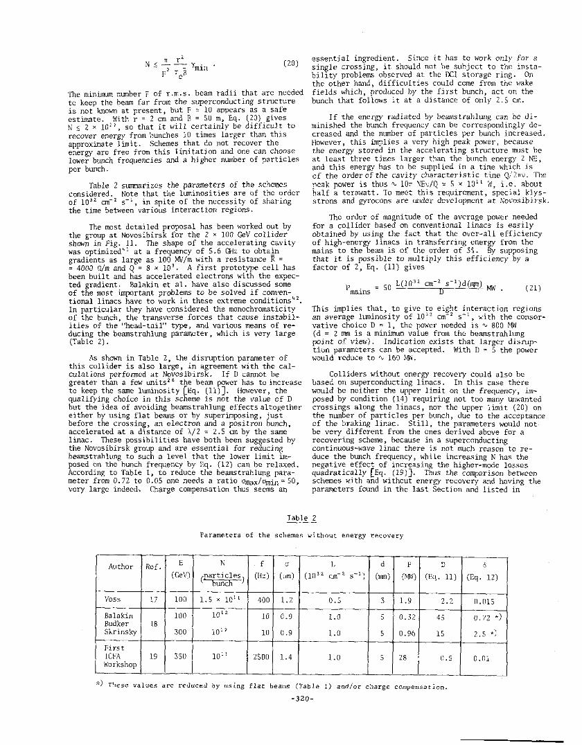
• To avoid these Pifficulties, Claudio Pellegrini and myself have proposed the scheme shown in Fig. 8, in which the energy is recovered but the particles are not 37 At every cycle new particles are produced by passing the beams through wiggler magnets, in which monochromatic photons of a few MeV are produced. In a 100 m long wiggler with a wavelength of 2.5 cm and a field of 0.37 T about 50 photons are produced. 1bis number is independent of the beam energy, while the photon energy increases with E as shown in Fig. 9. Above about lSO GeV, more than one electron and one positron per incident particle are produced by these photons in
-318-
a target thickness of less than one tenth of a_ radiation length within the acceptance of a very conventional collector working at a few MeV 3 7
•
WIGGLERS • _
~ ~ /~ ~-........ __.!.. .!..-
2 () ~"'""':~~~ e· COOLING RING(S) e*COOLING AING!Sl
Fig. 8 In this scheme 37 the energy is recovered but the particles are not. The low-energy po~itrons and electrons are produced by the photons radiated by the beams in wiggler magnets.
50
> w 40 ~
~
> ~ 30 ~ w z w
z 0 20 ~ 0 r ~
10
0
----
150 200 250 300
E (GeV)
350
~ r
0.!5 t;
400
z 'j z 0
ti ~ ~
Fig. 9 Energy dependence of the photon energy.produced in a wiggler of 2.5 cm wavelength and 0.37 T fLeld, The dashed curve gives the target thickness needed for a 100 m wiggler to produce one low-energy positron per electron.
Each particle loses less than 1 \ of it~ energy in traversing the wiggler, so that, by throwing aw~y th~ particles after a single pass, one does not modify either the economy of the energy recovery scheme or the procedure adopted at the beginning of this section to choose the parameters.
4. Colliding linacs without energy recovery
The beam power of the 2 x 250 GeV peloron is ~ 150 MW for a ltoninosity of 10 33 an- 2 s- 1 • Since this power is smaller than the power going into the linac (Fig. 7), it is worth while asking whether a scheme without energy recovery could not be advantageous. In this case one can use room-temperature linacs, whose technology is well tlllderstood. Schemes of this type have recently been considered by Voss 1 ~, by the ~roup at Novosibirsk15 and at the First ICFA Workshop1
•
Until a few months ago, in all schemes it was . assumed that the needed positrons would be produ~ed in a target illuminated by the used electron be~. Figure 10 displays a compilation of data and computations on the
10 1
' " ' ' " 0
>-SACLAY <( I0-2 ..
ll'. .. • DESY
• SLAC
E (GeV I
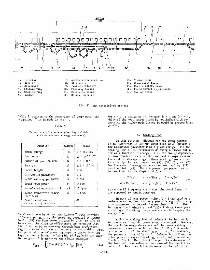
Fig. 10 Yield of positrons as a function of the ~ne~gy of the electrons impinging on a target of 1-2 radiation lengths (the optimurii. thickness varies logarithmically with energy). The points from Saclay 38 and DESY 39 are measu~ed with collectors of different acceptances. The points of SLAC have been computed with a very sop~isticated program and the line extrapolates them to higher energies.
Yields of positrons produced by electrons of energy E d . . 1 ths39-~Q iJllpinging on a target of about 1.5 ra iat1on eng .
The acceptances of the positron focusing systems are not exactly comparable, but the extrapola~ion of the existing infonnation allows a safe conclusion: for electron energies E ~ 90 GeV the (low-energy) positron current is larger than the impinging electron current, and the positron beam can be produced by the used electron beam downstream of the interaction point. However, the realization of a target that can absorb a power of some 10 ~is not a trivial problem. Recently, to overcome this difficulty, use of wiggler magnets has been pro~ . posed by Balakin and Mikhailichenko41 and by Pellegrm1 and myself37
• (Some properties of such wigglers were shown in Fig. 9.) The fonner authors have also computed the polarization that can be obtained ~y means.of an helical wiggler, arriving at the very l~terest1ng conclusions that the electrons and the positrons could be longitudinally polarized to ~ soi. The prod~ction of possibly polarized intense positron bWlches is no longer a problem after these recent developments.
If the energy is not recovered in the opposite linac the emittance can grow in the interaction point and thus the.number of particles per btlllch.c~ be larger. In a peloron the emittance due to.the ~ol~1s1on [Eq. (15)] has to be such that the beam remains w1 thin the acceptance of the linac also when its energy is reduced to ~ 1 GeV, i.~. when Ymin ~ 2 x 10~. 1he lin~c.accept~ce is 1Tr2Ymin/13, where r is the radius o~ the 1r1s and B is the amplitude function along the lmac, and from Eq. (15) it follows that for recovering the energy
-319-
TI r' N.$--Y ·
F2 r B min e
(20)
The minimum number F of r.m.s. beam radii that are needed to keep the beam far from the superconducting structure is not known at present, but F ~ 10 appears as a safe estimate. With r = 2 cm and B = SO m, Eq. (20) gives N $ 2 x 10 11 , so that it will certainly be difficult to recover energy from bunches 10 times larger than this approximate limit. Schemes that do not recover the energy are free from this limitation and one can choose lower bW1ch frequencies and a higher number of particles per bunch.
Table 2 stmUTiarizes the parameters of the schemes considered. Note that the 11..D'Tl.inosities are of the order of 10 32 on- 2 s- 1 , in spite of the necessity of sharing the time between various interaction regions.
The most detailed proposal has been worked out by the group at Novosibirsk for the 2 x 100 GeV collider shown in Fig. 11. The shape of the accelerating cavity was optimized41 at a frequency of 5.6 GHz to obtain gradients as large as 100 MV/m with a resistance R = = 4000 n/m and Q = 8 ~ 10 3
• A first prototype cell has been built and has accelerated electrons with the expected gradient. Balakin et al. have also discussed some of the most important problems to be solved if conventional linacs have to work in these extreme conditions 42
•
In particular they have considered the monochromaticity of the blll"l.ch, the transverse forces that cause instabilities of the "head-tail" type, and various means of reducing the beamstrahllillg parameter, which is very large (Table 2).
As shown in Table 2, the disruption parameter of this collider is also large, in agreement with the calculations perfol1!led at Novosibirsk. If D caIU1ot be greater than a few uni ts 2 6 the beam pgwer has to increase to keep the same luminosity [Eq. (11)]. However, the qualifying choice in this scheme is not the value of D but the idea of avoiding beamstrahllillg effects altogether either by using flat beams or by superimposing, just before the crossing, an electron and a positron bunch, accelerated at a distance of A/2 ~ 2.5 an by the same linac. lbese possibilities have both been suggested by the Novosibirsk group and are essential for reducing beamstrahlung to such a level that the lower limit imposed on the bunch frequency by Eq. (12) can be relaxed. According to Table 1, to reduce the beamstrahllU1g parameter from 0. 72 to 0.05 one needs a ratio omax/Omin ~ 50, very large indeed-. Charge compensation thus seems an
essential ingredient. Since it has to work only for a single crossing, it should not be subject to the instability problems observed at the DCI storage ring. On the other hand, difficulties could come from the wake fields which, produced by the first bunch, act on the bunch that follows it at a distance of only 2.5 cm.
If the energy radiated by bcamstrahlwig can be diminished the blll1ch frequency can be correspondir.gly decreased and the number of particles per bunch increased. However, this implies a very high peak power, because the energy stored in tJ1e accelerating structure must be at least three times larger than the bunch energy 2 NE, and this energy has ·to be supplied in a time which is cf the order of the cavity characteristic time Q/2nv. The r,eak power is thus "" !OTI \'Ev/Q ' 5 x 10 11 W, i.e. about half a terawatt. To meet this requirement, special klysstrons and gyrocons are under development at Novosibirsk.
The order of magnitude of the average power needed for a collider based on conventional linacs is easily obtained by using the fact that the over-all efficiency of high-energy linacs in transferring energy from the mains to the beam is of the order of 3i. By supposing that it is possible to multiply this efficiency by a factor of 2, Eq. (11) gives
L(lO'' cm-' s- 1 Jd(mm) P mains = SO MW . (21)
This implies that, to give to eight interaction regions an average luminosity of 10 32 cm- 2 s- 1 ~ with the conservative choice D ~ 1, the power needed is~ 800 MW' (d ~ 2 rrun is a minimum value from the beamstrahlung point of view). Indication exists that larger disn.iption parameters can be accepted. With D = 5 the power would reduce to '\, 160 M'tlJ.
Colliders without energy recovery could also be based on superconducting linacs. In this case there would be neither the upper limit on the frequency, imposed by condition (14) requiring not too many unwanted crossings along the linacs, nor the upper limit (20) on the number of particles per bunch, due to the acceptance of the braking linac. Still, the parameters would not be very different from the ones derived above for a recovering scheme, because in a superconducting continuous-wave linac there is not much reason to reduce the bunch frequency, while increasing N has the negative effect of increasing the higher-mode losses quadratically (Eq. (19)]. Thus the comparison between schemes with and without energy recovery and having the parameters found in the last Section and listed in
Table 2
Parameters of the schemes without energy recovery
Author Ref. E N f a L d p D
(GeV) crarticles) Duncfi
(Hz) (um) (10 32 enc' s-1) (mm) (MW) (Eq. ll)
Voss 17 100 l.Sxl011 400 1.2 o.s 3 1.9 2.2
Bal akin 100 10 I 2 10 0.9 1.0 5 0.32 45 Budker 18 Skrinsky 300 10 12 10 0 .9 1.0 s 0.96 15
First ICFA 19 350 101 l 2500 1.4 1.0 s 28 o.s Workshop
*) These values are reduced by using flat beams (Table 1) and/or charge compensation.
-320-
6
(Eq. 12)
0.015
0. 72 • )
2. 5 • J
0.01
1. Injector 2. Booster 3. Debuncher 4. Storage ring S. Cooling ring 6. Buncher
7. Accelerating sections 13. Photon beam 8. RF sources 14. Conversion target 9. Pulsed deflector 15. Used electron beam
10. Focusing lenses 16. Fixed target experiments 11. Colli5ion point 17. Second stage 12. Helical wiggler
Fig. 11 The Novosibirsk project
Table 3, reduces to the COTnparison of their power consumption. This is made in Fig. 7.
I I i !
Table 3
Parameters of a superconducting collider (with or without energy recovery)
Quantity Symbol Value
Total energy 2E 2 x 250 GeV
Luminosity L I
103 3 on-2 s-1
Number of part./bWlch N
I 7.2 x 101 0
Bunch/s f 2.5 x 10" Hz
Bunch length I d I 5 nm 1 I Disruption parameter
' D
l l.D
BeamstrahlWlg parameter I 0 o. 75%
I Total beam power p 1 144 MW
Nonnalized emittance x s ES 10- 5Bmn
Bunch transverse radius 0 1.0 µm (S=Scm)
Fraction of energy 4j extracted by a bunch
As already done by Hutton and Richter 3 ~ with somewhat different parameters, the power was computed by adding to Eq. (19) the beam power divided by 0.70 (to take into account the klystron efficiency) and assuming that 33% of it can be recuperated through heat production. Figure 7 shows that energy recovery is worth while. From the point of view of power conswnption the optimum voltage per metre is on the low side (4.5 MV/m in our case) and in general is given by the simple equation
' Vopt [ ( (l-s)kN 2 fv 2
+ P phllR Q] 2
• (22)
V l -R v-l For ~ ~ 1 it varies as betause ~ v and Q ~ while if the heat losses ~ould be negligible with re-' spect to the higher-mode losses it would be proportional to vo/'<.
S. Scaling laws
In this Section I discuss the following points: i) the variation of varjous quantities as a function of the disruption parameter D at a given energy; ii) the scaling laws of the parameters defining a linear collider as a function of energy; iii) the energy dependence of some rough estimate of the cost and a comparison with the cost of storage rings. These scaling laws are determ:ined by the basic equations (4), (5), (6), and (7). For the case of energy recovery, we must add Eq. (14) and the limit (20). For the present purposes they can be rewritten in the simplified fonn
D "-' N/Eo 2
(23) P "-' ENf ,
since the RF frequency v and thus the bunch length d are supposed to ~emain constant.
In most of this presentation, D ~ 1 was used as a reference value, but it is very probable that the disruption parameter can be made larger than 1 24 ' 2 ~. This increases the luminosity, and Table 4 shows three possible ways of scaling the parameters while keeping the energy fixed.
With the scaling laws of column A the luminosity increases as D and the power remains constant. However, the bunch frequency decreases and the beamstrahlung parameter increases as 02
, so that for D ~ 2 it would become too big if the starting point is, for instance, the parameter list of Table 3. Columns B and C display other possible ways of scaling, P "' 1, and give either 0 "-'Dor O "' 1. The price to be paid is a decrease of the beam radius o and/or an increase of the bunch frequency f. In column B the decrease of the radius is
-3Z1-
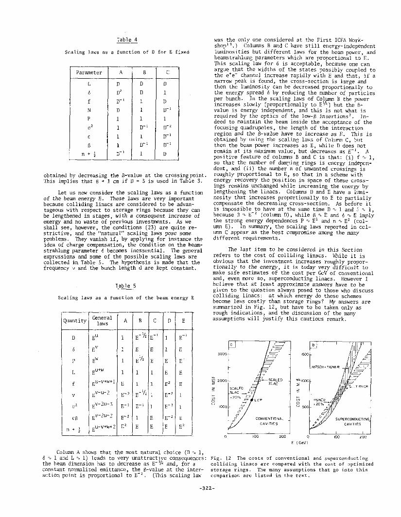
Table 4
Scaling laws as a function of D for E fixed
' Parameter A B c
L D 0 D
6 o' 0 1
f o-1 1 0
N D 1 0-1
p 1 1 1
a' 1 0-1 o-'
£ 1 1 0-1
s 1 0-1 0-1
n + ' 0-1 1 D ' J
obtained by decreasing the S-value at the crossing point. This implies that B = 1 cm if D = S is used in Table 3.
Let us now consider the scaling laws as a function of the beam energy E. These laws are very important because colliding linacs are considered to be advantageous with respect to storage rings because they can be lengthened in stages, with a consequent increase of energy and no waste of previous investments. As we shall see, however, the conditions (23) are quite restrictive, and the "natural" scaling laws pose some problems. They vanish if, by applying for instance the idea of charge compensation, the condition on the beamstrahlung parameter 6 becomes inessential. The general expressions and some of the possible scaling laws are collected in Table 5. The hypothesis is made that the frequency v and the bllllch length d are kept constant.
Tab 1 e 5
Scaling laws as a function of the beam energy E
Quantity General A B c D E laws
D Eu 1 E- i1z E-1 1 E-1
0 Ev 1 E E 1 E
p Ew 1 E i/2 E E E
L Eu+w 1 1 1 E E
f Eu-v+w+l E 1 1 E' E
v Ev-u-2 E-' E-1/2 1 E-' 1
a' Ev-2u-3 E-' E-1 1 E-' 1
ES Ev-2u-2 E- z 1 E E-2 E
I Eu-v+w+2 E' E E E E' n + ' I .
Colurrm A shows that the most natural choice (D ~ 1, 8 rv 1 and L rv 1) leads to very unattractive consequences: the beam dimension has to decrease as E-o/2 and, for a constant normalized emittance, the B-value at the interaction point is proportional to E- 2 • (This scaling lav.·
was the only one considered at the First ICFA Workshopt 9.) ColU1TU1s Band C have still energy-independent luminosities but different laws for the beam power, and beamstrahlung parameters whid1 are proportional to E. This scaling law for 6 is acceptable, because one can argue that the widths of the states possibly coupled to the e+e- channel increase rapidly with E and that, if a narrow peak is found, the cross-section is large and then the luminosity can be decreased proportionally to the energy spread O by reducing the ntmlber of particles per bLUlch. In the scaling laws of Colµmn B the power increases slowly (proportionally to EV2 ) but the Bvalue is energy independent, and this is not what is required by the optics of the low-B insertions 3 • Indeed to maintain the beam inside the acceptance of the focusing quadrupoles, the length of the interaction region and the $-value have to increase as E. This is obtained by usine the scalin3 la\~'S of Colurm C, but then the beam power increases as E, while D does not remain at its maximum value, but decreases as E- 1 • A positive feature of colUilUls B and C is that: (i) f ~ 1, so that the number of dampinp; rings is energy independent, and (ii) the number n of unwanted crossings is roughly proportional to E, so that in a scheme with energy recovery the position in space of these crossings remains unchanged while increasing the energy by lengthening the linacs. Columns D and E have a luminosity that increases proportionally to E to partially compensate the decreasing cross-section. As before it is impossible to have at the same time D ~ 1 and S rv 1, because J3 '\, E- 2 (column D). while B '\, E and 6 rv E imply the strong energy dependences P rv E2 and n ~ E2 {colLUTUl E). In surrnnal)', the scaling laws reported in column C appear as the best compromise among the many different requirements.
The last item to be considered in this Section refers to the cost of colliding linacs. While it is obvious that the investment increases roughly proportionally to the energy, it is today very difficult to make safe estimates of the cost per GeV of conventional and, even more so, superconducting linacs. However I believe that at least approximate answers have to be given to the question always posed to those who discuss colliding linacs: at which energy do these schemes become less costly than storage rings? ~fy answers are surrnnarized in Fig. 12, but have to be taken only as rough indications, and the discussion of the many asslml.ptions will justify this cautious remark.
3000
~
~ 2000
;o:::: SCALED
~ m 0 u
1000
0
CONVENTIONAL
CAVITIES
100 WO
1500
RITSON~ TIGNER
_TIGNER
SUf>ERCONOUCTING
CAVITIES
~~~~~~~_____[_ () 100 200
E (GeVJ
Fig. 12 The costs of conventional and superconducting colliding linacs are compared with the cost of optimized storage rings. The many assumptions that go into this comparison are listed in the text.
-322-
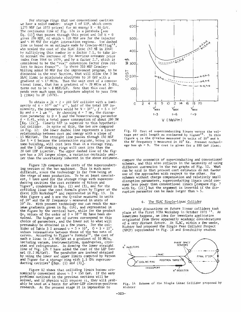
For storage rings that use conventional cavities we have a solid number: stage 1 of LEP, which costs 1275 MSF (at 1979 prices) for an energy E = 86 GeV. The continuous line of Fig. 12a is a parabola [see Eq. (l)] that passes through th~s point and fo~ ~ = 0 gives 200 J\t.SF, of which "" 120 MSF are for the inJ ector and,,_, 80 J\1SF for eight interaction regions. The dashed line is based on an estimate made bv Crowley-Milling" 3
,
who scaled the cost of the SLAC lin8-c (62 M$ in 1964) by multiplying this number by a fac~or 2.1, to take.into account the increase of the American consumer price index from 1964 to 1979, and by a factor 2.7, which is considered to be the "real" conversion factor from dollars to Swiss francs 44
• To these 350 MSF CrowleyMilling added SO MSF for the improvement program, to be discussed in the next Section, that will allow the 3 km SLAC linac to accelerate electrons to SO GeV with a gradient of"" 17 MV/m. Thus the Wlit cost of a conventional linac, that has a gradient of"" 20 ~Im at 3 Q-lz, turns out to be"" 8 MSF/GeV. Note that this cost depends very much upon the procedure adopted to pass from $ (1964) to SF (1979).
To obtain a 2E = 2 x 100 GcV collider with a luminosity of 4 x 10 32 cm- 2 s- 1 , half of the total LEP luminosity, the parameters would be N = 10 11
, f = 5 x 10 3
Hz and a= 1 µm ~ 3 • By choosing d = 7 rrnn, the disruption parameter is D = S and the bean~trahltmg parameter cS = 0. 4 i, with a total power consumption o~ about 200. ~.n·~ [Eq. (21)]. Clearly LE~ is s~perior to this hypothetical collider. In spite of this, the two are compared in Fig. 12: the lower dashed line represents a linear relationship between cost and energy with a slope of 15 MSF/GeV. The straight line passes through 150 ~!SF for E = o because the interaction regions, being in the same building, will cost less than in a storage ring, and the 1 GeV damping rings will cost le~s than the . 20 GeV LEP injector. The upper dashed line of the figure has a 20% larger slope, a variation certainly smaller than the uncertainty inherent in the above estimate.
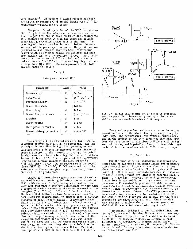
Figure 12b compares the costs of t~e superconducting version of the two machines .. This is much.more difficult, since the technology is far from heing ~t the stage of mass production. To be at least consistent I have used for the storage ringe with superconductin~ cavities the cost estimate of Ritson and Tigner , condensed in Eqs. (1) and (3), and for the colliding linac the cost fonrrula given by Tigner at the first ICFA Workshop 2 e and represented in Fig. 13. In this figure q and h are the Q-value measured in units of 10 9 and the RF frequency v measured in units of 10 9 Hz. With present technology one can reach the.maximLUn gradients given in Eq. (16), and represented in the figure by the vertical bars, while for the product Qv, values of the order of 9 x 10 18 Hz have been o~tained. The higher set of curves correspond to t~is choice of parameters, and the lower set to what will prest.unably be obtained in a few years. For the col~ lider of Table 3 I assumed v = 3 x 10 9
, Q = S x 10 , values intennediate between those of the two sets of curves. According to Tigner's fonnula 28
, the cost of such a linac is 2.6 M$/GeV at a gradient of 10 MV/m, including vacuum, instrumentation, quadrupoles, cryostat and refrigerator. In drawing the lower straight line of Fig. 12b I have added the cost of the LEP ttmnel (0.2 M$/GeV). The parabolae are instead obta~ned by using the lower and upper limits computed by Ritson and Tigner for a storage ring with 1.5 Q-lz superconducting cavities' [Eqs. (1) and (3)].
Figure 12 shows that colliding linacs become economically convenient above~ 2 x 150 GeV. If the many problems outlined in the previous sections will be solved, and if physics will require it, they will ~robably be used as a basis for after-LEP electron-positron research. At the present stage it is impossible to
600
500
400
-<A-
::< 300
f-(J)
0200 u
100
0 2 4
______ ! __ ._. - i -.:: ~ °'""'.
•. ,· .
1
1 ,.90»
. '·• • I ···· .. ::.:.::.~.~ .-.:.__-. ~: = ~ ::6~~:.:
6 9 10 12 14 16 18 20 I
VMAX I
VMAX I
VMAX
f•3 f. 6 f. 9
v ( MeV!m)
Fig. 13 Cost of superconducting linacs versus the voltage per unit length as estimated by Tigner 28 • In this figure q is the Q-value measured in units of 10 9 and h the RF frequency v measured in 10 9 Hz. Present technology has qh ~ 9. The cost is given for a 100 GeV linac.
compare the economics of superco~ducting and 7onventio~al schemes and this also reflects 1n the necessity of using differe~t currencies in the two graphs of Fig. 12. Vfrlat can be said is that present cost estimates do not favour one of the approaches with respect to the other. For schemes without charge compensation and relatively small disruption parameters, superconducting linacs could constune less power than conventional linacs [compare Fig. 7 with Eq. (21)] but the argument is inverted if the disruption parameter can be made larger than~ S.
6. The SLAC Sinele-Linac Collider
Lively discussions on future linear colliders took place at the First !CF~ WorkshoI? in C:X:tober 1~78 ~ 9
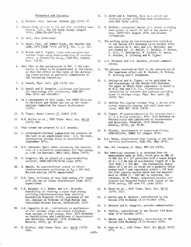
• A3 somet:imes happens, an idea for lmllediate appli::ation. originated from these apparently acad~mi~ considerations of a very distant future. At SLAC, within a few weeks, Richter had proposed the Single Pass Collider Project (SPCP).represented in Fig. 14 and feasibility studies
PHASE SPACE ± SENSORS
e INJECTORS ~
~~~~~~~__;L~l~N~AC::_~~~~;:-<.' ------------
FINAL STEER(
e+ COOLING RING POSITRON TARGET
TRANSPORT I e-f' BOOSTER
Fig. 14 Richter
Scheme of the Single Linac Collider proposed by
-323-
were started22 . At present a budget request has been put to IDE to obtain 800 k$ in the fiscal year 1980 for preliminary engineering and design.
The principle of operation of the SPCP (named also SLIC, Single Linac Collider) can be described as follows. A positron and an electron btmch are accelerated at a distance of about 20 m in the linac and collide after having travelled around half of the ring. The centring of the two bunches is controlled by the measurement of the phase-space sensors. 1he positrons are produced by a multibunch electron beam ("scavenging beam") which is injected behind the positron and electron blll1ches and hits the positron target. These positrons are boosted to~ 1 GeV and their emittance is reduced to ~ ~ 3 x 10-s mn in the cooling ring that has a large tune (Q ~ 100). 1he main parameters of SLIC are collected in Table 6.
Table 6
Main parameters of SLIC
Parameter Symbol Value
Beam-energy E 50 GeV Luminosity L 1030 cm-2 s-1
Particles/bunch N 5 x 101 0
Bunch frequency f 180 Hz Bunch length d 1-3 mm
Normalized emittance E 3 x lo- s mn
6-value s 1 cm
Bl.Ulch radius a 1.8 \Jlll
Disruption parameter D "' o.s Beamstrahlung parameter a "' 6 x io-~
The energy will be reached when the full Sr.AC development program SLED II will be completed. 'Ihe SLED principle is described in Fig. 15: by means of two cavities and a 3 dB coupler inserted on the line which joins a klystron to the accelerator cavity, the pulse is shortened and the accelerating field multiplied by a factDr of about 2 45 A first phase of the improvement program has already increased the SLAC energy to ~ 35 GeV, and~ 50 GeV will be reached with the second phase (SLED II). In SLIC, SO GeV are aimed at to obtain centre-of-mass energies larger than the presumed threshold of z0 production.
During 1979 preliminary measurements of the emittance of bunches containing 10 9 electrons were made at SLAC, with the result that, during acceleration, the invariant emittance E does not deteriorate by more than a factor of 2 with respect to the value measured at low energies (3 x 10- 5 lTTTI). Effects of the first bunch on the bl.Ulch that follows it have been observed and the conclusion was reached that, to control them, a minimlllTI distance of about 20 m is needed. Calculations have shown that for 5 x 10 10 electrons in a bunch an energy spread of ±0.1% is achievable by properly phasing the bunch in the accelerator. The stability of the terrain on a very short time scale (~ l/f) was measured and seismic disturbances with a r.m.s. value of 0.5 µm were observed. A preliminal)' scheme for correction of the chromatic aberrations for a 6p/p z ±0.5% was worked out~ 6 : it turns out that the needed magnetic system is very long, at least ten times the space left free for the interaction region, i.e. about 100 m. The last quadrupoles will have to be stable to within 1 µm ~ 7
Etccs I I
----<KLYSTRON)>---...0...-----j ACCELERATOR
Fig. 15 and the shifter
SLED CAVITY CAVITY #I "*"2
3dB COUPLER ~~~~~-< ACCELERATOR
In the SLED scheme the peak field increased by and two cavities with a
RF pulse is shortened adding a 180° phase 3 dB coupler.
These and many other problems are now llllder active investigation with the aim of having a design ready by July 1980. The enthusiasm of the group of people working on the project is the best guarantee that many problems that are colliJlon to all linac colliders will be better understood, and hopefully solved, in times which are much shorter than what one could foresee one year ago.
7. Conclusion
For the time being no fundamental limitation has been folllld to the use of colliding linacs for producing electron-positron collisions at energies much larger than the ones attainable with LEP, if physics will require it. This is very fortunate because, as discussed by Keil 3
, storage rings are limited to energies smaller than~ 2 x 200 GeV. However, the lack of fundamental limitations is not sufficient to guarantee that some paperwork will eventually generate reliable hardware. Here also the situation is favorable, because three inde·· pendent lines of development will produce essential infonnation in the near future: the CERN programme on superconducting cavities for the second stage of LEP, the Single Pass Collider Project at SLAC and the develorments of the Novosibirsk project. There are thus many reasons to believe that, in the next years, we shall still hear a lot about colliding linacs.
I am greatly indebted to the "colliding linac community" for many enlightening discussions and constructive criticism. In particular I would like to thank V. Balakin, M. Crowley-Milling, A. Hutton, E. Keil, B. Richter, A. Skrinsky, K. Steffen and M. Tigner. I as also grateful to P. Bernard, H. Lengeler, E. Picasso and W. Schnell for many discussions on superconducting and conventional cavities.
-324-
References and footnotes
1. B. Richter, Nucl. lnstrum. Methods 136 (1976) 47.
2. Design study of a 22 to 130 GeV e+e- colliding beam machine (LEP)~ The LEP Study Groups (August 1979), CE~~/ISR-LEP/79-33.
3. E. Keil, this Conference.
4.
5.
W. Bauer, Proc. LEP SLUlllTler Studyj Les Houch es and CERN, 1978 [CERN 79-01 (1979) , Vol. 2, p. 351.
D. Ritson and H. Tigner, Large electron-positron storage rings using superconducting RF acceleration; a feasibility study 3 CLNS-406, Cornell Univ. (1978).
6. Note that in the optimization of Ref. 5 the luminosity is taken to be proportional to the energy, so that the effect on the rates of the decreasing cross-section is partially compensated by the increasing luminosity.
7. U. Amaldi, Phys. Lett. 61B (1976) 313.
8. U. Amaldi and H. Lengeler, Collinear accelerators for high-energy e+e- collisions 3 CERN-SD-7 (May 1976) and VBA/O·!S/7.
9. As a consequence of this study, the IUPAP Division of Particles and Fields has set up the International Corrunittee for Future Accelerators (ICFA).
10. !v[. Tigner, Nuovo Cimento 37 (1965) 1228.
11. R.H. Miller et al., IEEE Trans. Nucl. Sci. NS-18 (1971) 604.
12. This scheme was proposed by S.S. Brodsky.
13. Y. Goldschrnidt-Clennont surnrnarized the contents of the talk in an LU1published note: A.N. Skrinsky, Intersecting Storage Rings at Novosibirsk (September 1971) .
14. W.P. Saranzev, Basic ideas concerning the constrution of a collective accele1•ator for high energy at JINR (in Russian), SMll-1003, Dubna (1973).
15. H. Lengeler, Who is afraid of a superconducting peloron?, CERN/!SR-LTD/76-30 (July 1976).
16. U. Amaldi, An unconventional scheme to obtain electron-positron c.ollisions at Ecm <-: 300 GeV, r.Driond meeting (1976) llllpublished.
17. G.A. Voss, Collision of very high energy e+e- beams with the use of linear accelerators (July 1977) unpublished.
18. V.E. Balakin, G.!. Budker and A.N. Skrinsky, Feasibility of creating a super high energy colliding electron-positron beam facility, Novosibirsk Preprint 78-101, presented at the Int. Seminar on Problems of High-Energy and Controlled Nuclear Fusion, Novosibirsk, 1978.
19. J.E. Augustin et al., Limitations on performance of e+e- storage rings and linear colliding-beam systems at high energy 3 Proc. ICFA Workshop on Possibilities and Limitations of Accelerators and Detectors, Fennilab, 1978 (Fennilab, Batavia, 1979), pp. 87-105.
20. B. Richter, IEEE Trans. Nucl. Sci. NS-26 (1979) 4261.
21. H. Gerke and K. Steffen, Note on a 45-100 GeV "electron swing" colliding-beam accelerator, DESY-PET 79/04 (1979).
22. B. Richter, Conceptual design of a linear colliding beam system to reach 100 GeV in the center of mass~ AATF/7913 (August 1979) and private infonnation.
23. The working group on electron-positron colliders of the Second ICFA Workshop (4-10 October 1979) was chaired by E. Keil and A.N. Skrinsky, and was fanned by: U. Amaldi, V. Balakin, A. Hutton, E. Keil, C. Pellegrini, B. Richter, G. Saxon, K. Steffen, R. Stiening and M. Tigner.
24. A.N. Skrinsky and V.E. Balakin, private corrunLmication.
25. The persons involved at SLAC in the calculation of the beam-beam effect are B. Richter, D. Ritson, R. Stiening and H. Wiedemann.
26. C. Pellegrini and ~1. Tigner, to be published in the proceedings of the Second ICFA Workshop. The paper on which their conclusion is based is by M.S. Uhm and C.S. Liu, Filamentation instability of electron and positron colliding beams in storage rings_. Phys. Rev. Lett. 43 (1979) 914.
27. K. Steffen The wiggler storage ring, a device with strong radiation damping and small beam emittance, DESY PET 79/05 (1979).
28. M. Tigner, RF superconductivity for accelerators -is it a hollow promise?, Proc. ICFA Workshop on Possibilities and Limitations of Accelerators and Detectors, Fennilab, 1978 (Fennilab, Batavia, 1979), pp. 81-86.
29. E. Picasso, Developments in superconductivity, CERN/SPC/444, ANNEX Ill (August 1979).
30. R.F. Koonz, Single-bunch beam loading on the SLAC two-mile accelerator, SLAC-195, (May 1976).
31. See, for instance, A. Chao, PEP-118 (1976).
32. The numerical constant k is obtained from the measurement made at SLAC, which gave an HML of SO MeV for N = 10 9 particles with a blU1ch length of d = 1.5 rrun and an accelerator length of 3 km (for SLAC A= 105 Jl!ll). The exponential dependence of k on d/A is valid for a geometry which scales with A and reproduces within ~ 20t both the SLAC results quoted above and the measurement at PETRA (A ~ 600 mm) as reported, for instance, by M. Henke, Comparison between calculated and measured higher mode losses of the PETRA cavity, LEP note 171 (Jlllle 1979).
33. W. Bauer et al., IEEE Trans. Nucl. Sci. NS-26 (1979) 3252.
34. A. Hutton and B. Richter, contribution to the Second ICFA Workshop (4-10 October 1979).
35. P. Bernard and H. Lengeler, private communication.
36. K. Steffen, contribution to the Second ICFA Workshop (4-10 October 1979).
37. U. Amaldi and C. Pellegrini, contribution to the Second ICFA Workshop (4-10 October 1979).
38. B. Aune et al., IEEE Trans. Nucl. Sci NS-26 (1979) 3773.
-325-
39. G. Stange, IEEE Trans. Nucl. Sci. NS-26 (1979) 4146.
40. M.B. James et al., A calculation of positron source yields, Proc. 10th Int. Conf. on High-Energy Accelerators, Protvino (IHEP, Serpukhov, 1977).
Q.
Discussion
(Perez, Orsay) It is well-known that in colliding rings the beams are more or less obliged to meet because of PCT. In linacs they are not obliged to meet, and you have a very small beam dimension. Can you corrment on that?
41. V.E. Balakin et al., Accelerating structure of A. This is a problem of which everyone is aware. Of course one can think of an automatic system to position the beam. There is some discussion in one of the papers of the Novosibirsk group on how to align the beam at such an accuracy and there are ideas at SLAC. But there is no final answer on how to do it.
colliding linear electron-positron beams (VLEPP), Novosibirsk preprint 79-83 (1979).
42. V.E. Balakin et al., Beam dynamics of colliding linear electron-positron beams (VLEPP)J Novosibirsk preprint 79-79 (1979).
43. M. Crowley-Milling, Clashing conventional linacs (October 1979) unpublished.
44. C. Roche, Resources given to high energy physics in 19?8 in the CERN Member States, DI/CP0/239 (July 1978).
45. Z.D. Farkas et al., Proc. of the 11th Int. Conf. on High Energy Accelerators, Stanford, 1974 (SLAG Stanford, 1974), p. 576.
46. D. Ritson, private COJ11TlW1ication.
47. B. Richter, seminar given at the Second ICFA Workshop (4-10 October 1979).
Q. (Gittelman, Cornell) talked about last, do cooling system to get
In the SLAC scheme that you they require some sort of a this luminosity?
A. Yes. They need a cooling ring and they claim they know the scaling law of it. I also think there is no problem from the point of view of cooling the positrons to the right emittance before injecting into SL.AC.
Q. (W. Paul, Univ. of Bonn) It is interesting to see from your slide that zero energy already costs 200 MSF!
-326-