Embed Size (px)
Citation preview

1
College of Engineering
Department of Mechanical Engineering
Fall Semester 2020-2021
Senior Design Project Report
Design of Turbojet Engine using Automobile Turbocharger.
In partial fulfillment of the requirements for the
Degree of Bachelor of Science in Mechanical Engineering
Group Members
Stu
den
t
Name Mohammed Aljishi Abdullah Alshaer Murtada Almozayen Ahmed Alsadiq
ID 201700994 201502694 201501591 201600718
Project Advisor: Dr.Mouhamad El Hassan

2
Abstract
Modern industry needs a simpler and faster optimum design methods to facilitate the
development process of gas turbine engine combustion chamber. The combustion chamber
design procedure requires the selection of optimum empirically derived formulas. This project
work is about researching, designing, and building jet-engines. This work focusses mainly on
design of an optimal combustion chamber geometry for turbojet engine. This design is
characterized by small dimensions, with enhanced possibilities for air and fuel mixture
circulation in the primary combustion zone to obtain good residence time in the flame tube,
higher turbulence, and optimal radial temperature distribution.
In this research work, various types of combustion, mixing is studied. The focus of
investigation is to explore the various types to enhance combustion mixing. Combustion
mixing depends on the port fuel injection or direct fuel injection, number of the particle, nozzle
angle and nozzle dimension.
After finishing research about combustion chamber optimum geometry, our main
objective is to design, develop and manufacture a simple turbojet engine in this project using
a large diesel car turbocharger on a small-scale level. Turbocharger consists of two chambers
that are connected by center housing and the two chambers contain a turbine wheel and a
compressor wheel connected by a shaft which passes through the center housing. The
turbocharger serves as an integrated compressor & turbine assembly that is suitably
manipulated and carefully converted into an open cycle constant pressure gas turbine. The
project mainly involves modelling and designing of combustion chamber using software
packages like AutoCAD, SolidWorks etc.; and then complete fabrication of the same by us.

3
The methods were then discussed and chosen in a way that would simplify the design work as
well as the construction of the engine.
In this research, we will apply our mechanical engineering understanding to design,
analyze and manufacture a jet engine. We will review literature regarding gas turbine engine
components, designed each component, and manufactured them accordingly. We then
assembled our engine and planned for testing.
Keywords– Jet engine, turbocharger, compressor, turbine, internal combustion engine,
combustion chamber, efficiency. direct injector, port injector, mixing efficiency.

4
Acknowledgment
We also want to extend our gratitude to the officials and the staff of the PMU for their guidance
and support. We would like to express our gratitude to our project advisor “Dr. Mohammad el
Hassan for his guidance in this project. Project leader wants to thank and acknowledge the effort
and team spirit shown by the team members during the project.

5
Table of Contents
Abstract ........................................................................................................................................................................ 2
Acknowledgment ......................................................................................................................................................... 4
List of Figure ................................................................................................................................................................. 8
List of Tables ................................................................................................................................................................ 9
1. Chapter: Introduction ........................................................................................................................................ 10
1.1 Project Definition ............................................................................................................................................. 12
1.2 Project Objectives ...................................................................................................................................... 13
1.3 Project Specifications ....................................................................................................................................... 13
1.4 Project Applications ......................................................................................................................................... 13
2. Chapter: Literature Review ................................................................................................................................ 15
2.1 Project Background .......................................................................................................................................... 15
2.1.1 History of jet engine.................................................................................................................................. 15
2.1.2 Application of jet engine ........................................................................................................................... 17
2.1.3 Working Principle of Jet Engine ............................................................................................................... 18
2.1.4 Parts of jet engine ..................................................................................................................................... 19
2.1.5 Types of Jet Engine ................................................................................................................................... 20
3. Chapter: System Design ..................................................................................................................................... 24
Design Constrains. ................................................................................................................................................. 24
Design methodology .............................................................................................................................................. 24
Theoretical Calculations of the Model ................................................................................................................... 25
Assumptions....................................................................................................................................................... 26
Diffuser. ............................................................................................................................................................. 27
Compressor ........................................................................................................................................................ 27
Turbine ............................................................................................................................................................... 28
Nozzle: ............................................................................................................................................................... 28
Brake Power of the Engine ................................................................................................................................ 28
BMEP ................................................................................................................................................................ 29
Air Density ......................................................................................................................................................... 29
Components and the Subsystems ......................................................................................................................... 29
Turbocharger Unit .............................................................................................................................................. 30
Turbocharger Compressor ................................................................................................................................. 30
Turbocharger Turbine ........................................................................................................................................ 31
Propelling nozzle ............................................................................................................................................... 31

6
Hydrostatic Unit ..................................................................................................................................................... 32
Hydraulic Oil Pump ........................................................................................................................................... 32
Oil Filter ............................................................................................................................................................. 32
Oil Storage Tank ................................................................................................................................................ 32
Radiator .............................................................................................................................................................. 32
Combustion system ............................................................................................................................................... 33
Combustion Chamber ........................................................................................................................................ 33
Ignition system ................................................................................................................................................... 34
Fuel Pumping System ........................................................................................................................................ 34
Theoretical Working of the model ......................................................................................................................... 35
Manufacturing and Assembly ................................................................................................................................ 36
Testing and Analysis ................................................................................................................................................... 39
Experimental Setup, Sensors, and data acquisition system ............................................................................... 39
Results Analysis and Discussion ....................................................................................................................... 39
5. Chapter: Project management........................................................................................................................... 42
Project plan ............................................................................................................................................................ 42
Contribution of the team members ....................................................................................................................... 42
Project Execution Monitoring ................................................................................................................................ 43
Challenges and Decision Making ........................................................................................................................... 43
Project Bill of Materials and Budget. ..................................................................................................................... 44
6. Chapter: Project Analysis ............................................................................................................................... 44
Life-long Learning .................................................................................................................................................. 44
Impact of Engineering Solutions ............................................................................................................................ 45
Contemporary Issues Addressed ........................................................................................................................... 45
Conclusion and Recommendations ........................................................................................................................... 45
Conclusion .............................................................................................................................................................. 45
Recommendations ................................................................................................................................................. 46
Reference ................................................................................................................................................................... 46
Appendix A: Progress Report ........................................................................................ Error! Bookmark not defined.
Calculations ............................................................................................................... Error! Bookmark not defined.
Modelling. ................................................................................................................. Error! Bookmark not defined.
Fuel Purchase ............................................................................................................ Error! Bookmark not defined.
Pipes Purchase .......................................................................................................... Error! Bookmark not defined.
Manufacturing .......................................................................................................... Error! Bookmark not defined.
Presentation .............................................................................................................. Error! Bookmark not defined.
Material purchase ..................................................................................................... Error! Bookmark not defined.

7
Department of Mechanical Engineering ....................................................................... Error! Bookmark not defined.
In partial fulfilment of the requirements for the .......................................................... Error! Bookmark not defined.
Progress Report ......................................................................................................................................................... 51
Pipes Purchase ....................................................................................................................................................... 51
Fuel Purchase ......................................................................................................................................................... 51
Manufacturing ....................................................................................................................................................... 52
Assembly ................................................................................................................................................................ 52
Testing .................................................................................................................................................................... 53
Video Submission ................................................................................................................................................... 53
Month 1: September .......................................................................................................................................... 54
List the tasks conducted this month and the team member assigned to conduct these tasks ........................ 54
Appendix B: 3D model and drawings ......................................................................................................................... 58

8
List of Figure
Figure 1.1: Turbojet Engine. ........................................................................................................................ 10
Figure 1.2: Compressor of Turbojet engine. ............................................................................................... 11
Figure 2.1: Hero’s Aeolipile (Source: Knight’s American Mechanical Dictionary, 1876). .......................... 16
Figure 2.2: (a) Albert Fonó's ramjet-cannonball from 1915. (b) Heinkel He 178, the world's first aircraft to
fly purely on turbojet power. ...................................................................................................................... 17
Figure 2.3: (a) The Whittle W.2/700 engine flew in the Gloster E.28/39. (b) Gloster Meteor F.3s. .......... 17
Figure 2.4: A JT9D turbofan jet engine installed on a Boeing 747 aircraft. ................................................ 18
Figure 2.5: Air flow through the Jet engine. ............................................................................................... 18
Figure 2.6: Parts of jet engine. .................................................................................................................... 20
Figure 2.7: Turbojet engine. ........................................................................................................................ 21
Figure 2.8: Turboprop engine. .................................................................................................................... 21
Figure 2.9: Turbofan engine. ....................................................................................................................... 22
Figure 2.10: Turboshaft engine. .................................................................................................................. 23
Figure 2.11: Ramjets engine. ...................................................................................................................... 23
Figure 3.1: Model of turbocharger Diffuser ................................................................................................ 24
Figure 3.2: Inner Liner Assembly ............................................................................................................... 24
Figure 3.3: Combustion Chamber ............................................................................................................... 25
Figure 3.4: T-s Diagram of Ideal turbojet engine cycle. .............................................................................. 27
Figure 3.5: Turbojet Engine Block Diagram ................................................................................................. 30
Figure 3.6: Schematic diagram of turbocharger ......................................................................................... 31
Figure 3.7: Hydraulic System. ...................................................................................................................... 33
Figure 3.8: Combustion System .................................................................................................................. 35
Figure 3.9: Simple Gas Turbine System ....................................................................................................... 36
Figure 3.10: Schematic Diagram of the Experiment Setup ......................................................................... 37
Figure 3.11: Turbo Charger ......................................................................................................................... 37
Figure 3.12: Final model of the turbojet engine. ........................................................................................ 38
Figure 4.1: Ts-Diagram of the turbojet engine. .......................................................................................... 40
Figure 5.1: Gantt Chart ............................................................................................................................... 42
Figure A.1: 3D model of the combustion chamber sub-assembly. ................ Error! Bookmark not defined.
Figure 0.2: Turbo Charger. ............................................................................. Error! Bookmark not defined.

9
List of Tables
Table 4.1: Calculated and the Experimental Results of the model. ............................................................ 40
Table 4.2 the bill of material for the project. .............................................................................................. 44

10
1. Chapter: Introduction
The gas turbine engine is a machine, which work according to the thermodynamic
Brayton Cycle by harnessing energy from a working fluid and converting the energy into a
useable form. Various types of gas turbines are designed to perform a range of tasks, but all
operate on similar principles. Air enters the engine, is compressed, mixed with fuel,
combusted, and then expanded through a rotating turbine. Due to the extreme temperatures and
high rotational speeds experienced by engine components, design and construction of a gas
turbine demands accuracy, informed material selection, knowledge of thermodynamics, and
the ability to model and machine metal components. From fine tolerance in space to resilience
to high temperatures and stress, the jet engine has gone through a revolution over the years,
with great improvements in performance, efficiency, and reliability. The most known jet
engines are the turbojet engine, the turboprop engine, the turbofan engine, the turboshaft, and
the ramjet engine. The major principle in all these engines are the same and they work
according to similar concepts as the internal combustion engine:
Figure 1.1: Turbojet Engine.

11
i. Suck: The engine sucks in a large volume of air through the fan and compressor stages. A
typical commercial jet engine takes in 1.2 tons of air per second during takeoff. The
mechanism by which a jet engine sucks in the air is largely a part of the compression stage.
Some engines have an additional fan that is not part of the compressor to draw additional
air into the system. This part is on left side in figure 1.
ii. Squeeze: Aside from drawing air into the engine, the compressor also pressurizes the air
and delivers it to the combustion chamber. The compressor is shown in figure 1 just to the
left of the fire in the combustion chamber and to the right of the fan. The compression fans
are driven from the turbine by a shaft. Compressors can achieve compression ratios more
than 40:1, which means that the pressure of the air at the end of the compressor is over 40
times that of the air that enters the compressor.
Figure 1.2: Compressor of Turbojet engine.
Figure 2 shows the green fans that compose the compressor gradually get smaller and
smaller, as does the cavity through which the air must travel. The air must continue moving
to the right, toward the combustion chambers of the engine, since the fans are spinning and
pushing the air in that direction. The result is a given amount of air moving from a larger
space to a smaller one, and thus increasing in pressure.
12
iii. Bang: In combustion chamber fuel is mixed with air to produce the bang, which is
responsible for the expansion that forces the air into the turbine. Inside the typical
commercial jet engine, the fuel burns in the combustion chamber at up to 2000 degrees
Celsius. The temperature at which metals in this part of the engine start to melt is 1300
degrees Celsius, so advanced cooling techniques must be used.
The combustion chamber has the difficult task of burning large quantities of fuel, supplied
through fuel spray nozzles, with extensive volumes of air, supplied by the compressor, and
releasing the resulting heat in such a manner that the air is expanded and accelerated to give a
smooth stream of uniformly heated gas. This task must be accomplished with the minimum
loss in pressure and with the maximum heat release within the limited space available. The
amount of fuel added to the air will depend upon the temperature rise required.
iv. Blow: The fourth part is focused on the outlet of the engine, the reaction of the expanded
gas the mixture of fuel and air being forced through the turbine, drives the fan and
compressor and blows out of the exhaust nozzle providing the thrust.
Thus, the turbine has the task of providing power to drive the compressor and accessories, by
extracting energy from the hot gases released from the combustion system and expanding them
to a lower pressure and temperature. To produce the driving torque, the turbine may consist of
several stages, each employing one row of moving blades and one row of stationary guide
vanes to direct the air as desired onto the blades. The number of stages depends on the
relationship between the power required from the gas flow, the rotational speed at which it
must be produced, and the diameter of turbine permitted.
1.1 Project Definition
This project consists of Design, fabrication, assembly and testing of a Jet Engine,
using a large diesel car turbocharger, on a small-scale level. The turbocharger serves as an

13
integrated compressor & turbine assembly which is suitably manipulated and carefully
converted into an open cycle constant pressure gas turbine. The project mainly involves
complex modeling, designing and analysis of combustion chamber using software packages
like AutoCAD, SolidWorks etc.; and then complete fabrication of the same completely by us.
1.2 Project Objectives
Following are the objectives of our project:
• To optimize the design procedure of the combustion chamber.
• To determine the design parameters, the design constraints, and their effect on chamber
performance.
• To construct a working scaled model of a turbojet engine using diesel car turbocharger
which will be self-sufficient and requiring no separate power sources to operate thus
allowing the unit to be mobile.
1.3 Project Specifications
Following are the initial design specification:
• The first constraint imposed by low cost involves the elimination of turbine blade cooling
and limits the combustor exit temperature to 1100 K maximum to assure safe and long
operation of turbine blades and nozzle guide vanes.
• The overall engine dimensions of 500 mm maximum length and 145 mm maximum
diameter dictated a short length and small diameter combustor.
1.4 Project Applications
A modern jet engine is truly a miracle of engineering. Jet engines see wide use in many
applications, aviation, and energy production among many others. Common applications of

14
modern gas turbines include producing auxiliary power for ground or aircraft systems, propelling
military aircraft at supersonic speeds, and driving the rotor system of helicopters.

15
2. Chapter: Literature Review
2.1 Project Background
In this section history of jet engines, applications, working principle and types of jet engines are
discussed.
2.1.1 History of jet engine
The basic principle used in jet engines has been known for a long time. It dates to
around 150 BC when the principle was used in the Aeolipile as shown in figure 2 [2], which is
a simple construction using a radial steam turbine. The steam exits through a nozzle creating
a spinning motion of a ball. All according to Newton’s third law.
The key to a practical jet engine was the gas turbine, extracting power from the engine
itself to drive the compressor. The gas turbine was not a new idea: the patent for a stationary
turbine was granted to John Barber in England in 1791. The first gas turbine to successfully
run self-sustaining was built in 1903 by Norwegian engineer Ægidius Elling. The interest
continued during the 1800s. But it wasn’t until Sir Frank Whittle of the Royal Air Force in the
1930s made the first patent for the jet engine and showed the possibilities through reliable
energy conversion. He made the first static test in 1937. Two years later, in 1939, it was a
German physicist named Hans von Ohain who made the first jet-powered-flight and
demonstrated the possibilities of the jet engines. The ideas came about improving the propeller
driven aircrafts of the time, where the main problem was the speed of the aircraft. The aircraft
of the time were closing in on the speed of sound, and sometimes getting too close, which
would result in shock waves being created, causing the propeller to shatter.
The jet engine allowed a continuous combustion and airflow. It was a big change
from the piston engines dominating the industry. At the time, the greatest struggle the

16
engineers had was to create a material that could withstand the temperatures generated in the
combustion chamber, since it would often lead to the turbines melting. The development of
the jet engine took off during World War II and performance was quickly raised because of
the efforts made to try to get any advantage possible. Thus, paving the way for the modern jet
engines.
Figure 2.1: Hero’s Aeolipile (Source: Knight’s American Mechanical Dictionary, 1876).
Following the end of the war the German jet aircraft and jet engines were extensively
studied by the victorious allies and contributed to work on early Soviet and US jet fighters.
The legacy of the axial-flow engine is seen in the fact that practically all jet engines on fixed-
wing aircraft have had some inspiration from this design. By the 1950s the jet engine was
almost universal in combat aircraft, except for cargo, liaison and other specialty types. The
efficiency of turbojet engines was still rather worse than piston engines, but by the 1970s, with
the advent of high-bypass turbofan jet engines fuel efficiency was about the same as the best
piston and propeller engines.

17
Figure 2.2: (a) Albert Fonó's ramjet-cannonball from 1915. (b) Heinkel He 178, the world's first aircraft to fly purely on turbojet power.
Figure 2.3: (a) The Whittle W.2/700 engine flew in the Gloster E.28/39. (b) Gloster Meteor F.3s.
2.1.2 Application of jet engine
Jet engines power jet aircraft, cruise missiles and unmanned aerial vehicles. In the
form of rocket engine, jet engine power fireworks, model rocketry, spaceflight, and military
missiles. Jet engine designs are frequently modified for non-aircraft applications, as industrial
gas turbines or marine powerplants. These are used in electrical power generation, for
powering water, natural gas, or oil pumps, and providing propulsion for ships and locomotives.
Industrial gas turbines can create up to 50,000 shaft horsepower.
Jet engines are also sometimes developed into, or share certain components such as
engine cores, with turboshaft and turboprop engines, which are forms of gas turbine engines
that are typically used to power helicopters and some propeller-driven aircraft.

18
Figure 2.4: A JT9D turbofan jet engine installed on a Boeing 747 aircraft.
2.1.3 Working Principle of Jet Engine
All jet engines work on the same principle. The engine sucks air in at the front with a
fan. A compressor made with many blades attached to a shaft spin at high speed and raises the
pressure of the air by compress or squeeze the air. The compressed air is then sprayed with fuel
and an electric spark lights the mixture. The burning gases expand and blast out through the nozzle,
at the back of the engine. The engine and the aircraft get thrust forward as the jets of gas shoot
backward. As the hot air is going to the nozzle, it passes through another group of blades called
the turbine. The turbine is attached to the same shaft as the compressor. Spinning the turbine causes
the compressor to spin. Figure 2.1 shows the air flow through the engine.
Figure 2.5: Air flow through the Jet engine.

19
2.1.4 Parts of jet engine
Following are the parts of jet engine:
• Fan - The fan is the first component in a turbofan. The large spinning fan sucks in large
quantities of air. Most blades of the fan are made of titanium. It then speeds this air up
and splits it into two parts. One part continues through the "core" or center of the
engine, where it is acted upon by the other engine components.
• Compressor - The compressor is the first component in the engine core. The
compressor is made up of fans with many blades and attached to a shaft. The
compressor squeezes the air that enters it into progressively smaller areas, resulting in
an increase in the air pressure. This results in an increase in the energy potential of the
air. The squashed air is forced into the combustion chamber.
• Combustor - In the combustor the air is mixed with fuel and then ignited. There are as
many as 20 nozzles to spray fuel into the airstream. The mixture of air and fuel catches
fire. This provides a high temperature, high-energy airflow. The fuel burns with the
oxygen in the compressed air, producing hot expanding gases. The inside of the
combustor is often made of ceramic materials to provide a heat-resistant chamber. The
heat can reach 2700°.
• Turbine - The high-energy airflow coming out of the combustor goes into the turbine,
causing the turbine blades to rotate. The turbines are linked by a shaft to turn the blades
in the compressor and to spin the intake fan at the front. This rotation takes some energy
from the high energy flow that is used to drive the fan and the compressor. The gases
produced in the combustion chamber move through the turbine and spin its blades. The
turbines of the jet spin around thousands of times. They are fixed on shafts which have
several sets of ball-bearing in between them.

20
• Nozzle - The nozzle is the exhaust duct of the engine. This is the engine part which
produces the thrust for the plane. The energy depleted airflow that passed the turbine,
in addition to the colder air that bypassed the engine core, produces a force when exiting
the nozzle that acts to propel the engine, and therefore the airplane, forward. The
combination of the hot air and cold air are expelled and produce an exhaust, which
causes a forward thrust.
The velocity of the air entering the nozzle is low, about Mach 0.4, a
prerequisite for minimizing pressure losses in the duct leading to the nozzle [4]. The
temperature entering the nozzle may be as low as sea level ambient for a fan nozzle in
the cold air at cruise altitudes. It may be as high as the 1000 K exhaust gas temperature
for a supersonic afterburning engine or 2200K with afterburner lit [5]. The pressure
entering the nozzle may vary from 1.5 times the pressure outside the nozzle, for a single
stage fan, to 30 times for the fastest manned aircraft at mach 3.[6]
Figure 2.6: Parts of jet engine.
2.1.5 Types of Jet Engine
Following are the types of jet engine:
• Turbojets: The basic idea of the turbojet engine is simple. Air taken in from an opening
in the front of the engine is compressed to 3 to 12 times its original pressure in compressor.
Fuel is added to the air and burned in a combustion chamber to raise the temperature of the
21
fluid mixture to about 1,100°F to 1,300° F. The resulting hot air is passed through a turbine,
which drives the compressor.
Figure 2.7: Turbojet engine.
• Turboprops: A turboprop engine is a jet engine attached to a propeller. The turbine at the
back is turned by the hot gases, and this turns a shaft that drives the propeller. Some small
airliners and transport aircraft are powered by turboprops.
Figure 2.8: Turboprop engine.
• Turbofans: A turbofan engine has a large fan at the front, which sucks in air. Most of the
air flows around the outside of the engine, making it quieter and giving more thrust at low
speeds. In a turbojet all the air entering the intake passes through the gas generator, which

22
is composed of the compressor, combustion chamber, and turbine. In a turbofan engine
only a portion of the incoming air goes into the combustion chamber. The remainder passes
through a fan, or low-pressure compressor, and is ejected directly as a "cold" jet or mixed
with the gas-generator exhaust to produce a "hot" jet. The objective of this sort of bypass
system is to increase thrust without increasing fuel consumption. It achieves this by
increasing the total air-mass flow and reducing the velocity within the same total energy
supply.
Figure 2.9: Turbofan engine.
• Turboshafts: This is another form of gas-turbine engine that operates much like a
turboprop system. It does not drive a propeller. Instead, it provides power for a helicopter
rotor. The turboshaft engine is designed so that the speed of the helicopter rotor is
independent of the rotating speed of the gas generator.

23
Figure 2.10: Turboshaft engine.
• Ramjets: The ramjet is the simplest jet engine and has no moving parts. The speed of the
jet "rams" or forces air into the engine. It is essentially a turbojet in which rotating
machinery has been omitted. Its application is restricted by the fact that its compression
ratio depends wholly on forward speed.
Figure 2.11: Ramjets engine.

24
3. Chapter: System Design
Design Constrains.
• The temperature of the working fluid should not exceed 1000oC
• The model should be self-sufficient and would be able to operate without any outside
assistance.
Design methodology
Designing of the model was done in SolidWorks. Different type of engines was analyzed to get
design ideas and ultimately for the selection of the most suitable design for the project. Then those
dimensions were used for modeling.
Figure 3.1: Model of turbocharger Diffuser
Figure 3.2: Inner Liner Assembly
25
Figure 3.3: Combustion Chamber
Theoretical Calculations of the Model
The Net thrust which will be generated by the engine could be calculated by using the equation
given below.
𝐹𝑁 = (�̇�𝑓 + �̇�𝑎𝑖𝑟)𝑉𝑗 − 𝑉�̇�𝑎𝑖𝑟
Where,
𝑉 = 𝑉𝑒𝑙𝑜𝑐𝑖𝑡𝑦 𝑜𝑓 𝑡ℎ𝑒 𝑎𝑖𝑟𝑐𝑟𝑎𝑓𝑡
𝑉𝑗 = 𝑒𝑥𝑖𝑡 𝑗𝑒𝑡 𝑠𝑝𝑒𝑒𝑑
�̇�𝑓 = 𝑓𝑢𝑒𝑙 𝑐𝑜𝑛𝑠𝑢𝑚𝑝𝑡𝑖𝑜𝑛 𝑟𝑎𝑡𝑒 𝑜𝑓 𝑡ℎ𝑒 𝑒𝑛𝑔𝑖𝑛𝑒

26
�̇�𝑎𝑖𝑟 = 𝐴𝑖𝑟 𝑚𝑎𝑠𝑠 𝑓𝑙𝑜𝑤 𝑟𝑎𝑡𝑒
The amount of thrust produced by the engine can be increased by increasing the exhaust velocity.
It will result in an increase in thrust with our increasing the mass flow rate of the air or mass flow
rate of the fuel could be increased to increase the thrust with our increasing exhaust speed. This is
the same process which is used in the engines of the modern commercial engines known as bypass
ratio.
For the purpose of thermodynamic calculations of the system, we have to make some
assumptions first to make calculations simple.
Assumptions
1. The system will be considered as steady-state control volume system
2. The air and the gasses in the system will be considered as ideal gases at each point of the
analysis.
3. Within the system effects of kinetic energy will be neglected.
4. Potential energy will be considered negligible for the system.
5. The work produced by the turbine of the engine will be considered equal to the energy
consumed by the compressor of the engine.
6. Pressure drop in the system will be considered zero for flow.
7. All of the processes will be considered as isentropic processes.
Calculations for different components of the engine are given below.

27
Figure 3.4: T-s Diagram of Ideal turbojet engine cycle.
Diffuser.
By considering mass and energy balance across the diffuser the enthalpy of the air after the
diffuser could be calculated as.
ℎ1 +𝑉1
2
2= ℎ𝑎 +
𝑉𝑎2
2
𝑉1 ≈ 0
ℎ1 = ℎ𝑎 +𝑉𝑎
2
2
Compressor
Pressure after the compressor could be calculated by using the compression ratio of the
compressor.
𝑝2
𝑝1= 𝜋𝑐

28
Turbine
The power produced by the turbine could be given by the following equation as we know the
power produced by the turbine will be equal to the power consumed by the compressor.
�̇�𝑡
�̇�=
�̇�𝑐
�̇�
Enthalpy of the air exiting the turbine could be given as below.
ℎ3 − ℎ4 = ℎ2 − ℎ1
ℎ4 = ℎ3 + ℎ − 1 − ℎ2
Nozzle:
By apply the Bernoulli’s equation across the nozzle
ℎ4 +𝑉4
2
2= ℎ3 +
𝑉52
2
By neglection the velocity of the gasses at the inlet of the nozzle.
𝑉5 = √2(ℎ4 − ℎ3)
Some of the other formulas used for the calculations of different parameters during calculations
are given below.
Brake Power of the Engine
Brake power of the engine is calculated by using the formula given below:
𝑃𝑏 = 2𝜋𝜏𝑁
Where
Pb=Power produced by the engine
29
T= Torque produced by the engine
N= Rotational Speed of the engine
BMEP
Brake mean effective pressure in the engine are calculated using equations given below.
𝑏𝑚𝑒𝑝 =4𝜋𝜏
𝑉𝑑
Air Density
Density of the air is calculated by using the equation given below
𝜌𝑖 =𝑝𝑖
𝑅𝑇𝑖
Where
pi=pressure of the gas
R=Gas Constant
Ti=Temperature of the gas
Components and the Subsystems
The turbojet engine could be divided into three major systems which are given below.
1. Combustion System of the Engine
2. Turbocharger System
3. Lubrication System of the Engine
The three major systems of the engine are made of several smaller subsystems. The three major
system and their subsystems could be seen in the figure below.

30
Figure 3.5: Turbojet Engine Block Diagram
Turbocharger Unit
The Turbocharger of an engine consist of Turbocharger along with Inlet diffuser and outlet
nozzle.
Turbocharger
The turbocharger is a device which is used to increase the pressure of the inlet air for an engine it
is usually a centrifugal compressor which is either rotated by a turbine powered by the exhaust of
the vehicle or by connecting the main power drive of the vehicle. The turbocharger increases the
power produced by the engine by increasing the amount of the air supplied to the cylinder in each
stroke.
Turbocharger Compressor
Turbocharger compressor is a centrifugal device which takes the air from the atmosphere at low
pressure and compresses it to a higher pressure with the help of mechanical power. In the

31
compressor air is drawn axially then it is accelerated to higher velocity and then expelled radially
out into the diffuser.
Turbocharger Turbine
Turbocharger turbine is made up of a turbine wheel and housing it is powered by the exhaust of
the engine. The exhaust of the engine is at a higher pressure than the pressure of the atmosphere
this pressure difference is used to drive the turbine which is connected to the compressor and drives
it as a result.
Propelling nozzle
Nozzle or exhaust nozzle is one of the most important components of a turbojet engine the turbojet
engines are used to produce jets. The power is in the form of the energy of the exhaust gases the
mechanical power produced by the engine is minimum. It is only used to drive the compressor and
some other important components. Most of the power produced by the engine is in the form of
gasses exiting at very high speed. The nozzle of an engines takes the exhaust from the turbine
which is at very high pressure and low velocity as these gasses passes through the nozzle their
potential energy is converted into kinetic energy.
Figure 3.6: Schematic diagram of turbocharger

32
Hydrostatic Unit
The hydrostatic system is used to lubricate the rotating parts of the engine. This system consists of
a hydraulic pump, oil filters and an oil storage tank.
Hydraulic Oil Pump
An oil pump is used to provide oil at constant pressure to the hydrostatic bearings of the engine.
For the oil and flow requirements of the engine, the external gear pump is the most suitable choice.
Oil Filter
Oil filters are very important in any engine the purpose of these filters is to remove any outside
particles from the oil which can cause damage to the system. Especially in internal combustion
engines or in the case of hydrostatic bearings where particles or small metallic pieces broken from
the machinery can block small holes which can hinder the flow of the oil and cause damage to the
engine. Loke in the piston of an internal combustion engine.
Oil Storage Tank
The oil storage tank is used to store the oil for the hydrostatic system as some of the oil is usually
lost during operation of the machinery to compensate for that and to provide flexibility in the
system usually an oil tank is used in lubrication systems.
Radiator
Radiators are used to exhaust the heat from the engine to the atmosphere. As engines like jet
engines and internal combustion engines use thermal energy to produce mechanical energy. this
combustion raises the temperature of the engine which can cause damage to the engine. To prevent
that usually a cooling system is integrated into the combustion engine. The cooling system uses
some type of fluid to transfer energy from the engine to the radiator where that energy is exhausted

33
to the atmosphere. Radiators usually have a large number of fins along with pipes caring the
coolant to increase the surface area of the radiator for better heat removal.
Figure 3.7: Hydraulic System.
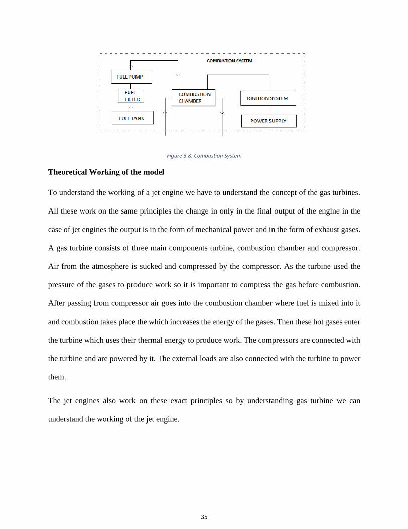
Combustion system
The combustion system of any system is the system which produces thermal energy from the
combustion of fuel. This consists of a fuel pump a combustion chamber and an ignition system.
Combustion Chamber
The combustion chamber of an engine is the chamber where the combustion of the fuel takes place
it could continue like in the case of jet engines or it could be periodic like in the case of the internal
combustion engine. In the jet engine where there is a continues supply of the fresh air it is difficult
to sustain a continuously burning flame. For this purpose, the combustion chamber of the engine
has a smaller internal cylinder with holes in it. The fuel injector nozzle is placed at the center of
the internal cylinder which sprays the fuel in the form of very fine droplets into the cylinder. The
internal cylinder could be divided into three different sections depending on the state of
combustion in them. These three sections are primary, secondary, and tertiary.

34
Ignition system
The purpose of an ignition system in any engine is to produce flame to start combustion. The
combustion system consists of a 230 V power supply which provides AC power for its operation,
an ignition coil, an ignition coil driver circuit, and a spark plug. The purpose of the ignition coil is
to provide high volt pulses of the current at regular intervals. The ignition coil is provided with
230V power and it delivers 15000V to the spark plug for ignition.
Fuel Pumping System
The purpose of the fuel pumping system is to provide fuel at high pressure into the combustion
chamber for combustion. Parts of the fuel combustion system are given below.
Fuel Tank
The purpose of the fuel tank is to store fuel its the part of the engine which holds the fuel for the
usage of the system. As fuels are flame able so special precautions should be taken to ensure the
safety of the fuel tank.
Fuel Filter
Fuel filters are an integral part of the fuel injection system used to remove any foreign particles or
paint chips which may be present in the unfiltered fuel. The removal of these foreign objects is
very important because these particles are very important because they can reduce the life of the
fuel pump and the fuel injector due to the abrasive action of them on these parts.
Fuel Pump
The fuel pump of any internal combustion engine is used to provide small quantities of the fuel to
the fuel injectors to produce good atomization of fuel. An internal gear pump is usually the most
suitable candidate for this type of applications.
35
Figure 3.8: Combustion System
Theoretical Working of the model
To understand the working of a jet engine we have to understand the concept of the gas turbines.
All these work on the same principles the change in only in the final output of the engine in the
case of jet engines the output is in the form of mechanical power and in the form of exhaust gases.
A gas turbine consists of three main components turbine, combustion chamber and compressor.
Air from the atmosphere is sucked and compressed by the compressor. As the turbine used the
pressure of the gases to produce work so it is important to compress the gas before combustion.
After passing from compressor air goes into the combustion chamber where fuel is mixed into it
and combustion takes place the which increases the energy of the gases. Then these hot gases enter
the turbine which uses their thermal energy to produce work. The compressors are connected with
the turbine and are powered by it. The external loads are also connected with the turbine to power
them.
The jet engines also work on these exact principles so by understanding gas turbine we can
understand the working of the jet engine.

36
Figure 3.9: Simple Gas Turbine System
Manufacturing and Assembly
For the manufacturing and assembly we started with the selection of the turbocharger of the car engine as
this is the most important part of the design and the whole design of the engine is built around it. The
selection f the turbocharger the 3D model of the engine was constructed and then the drawings anf the bil
of material was generated. After the finalization about the material required for the construction materials
were acquired. We hired a workshop for the purpose of the cutting and welding sifferent parts of the engine
which were used in the manufacturing of the engine. During the process of machining and welding the
wekers were superwised by the membors of the team to endure that the product is according to the design.
The final assambly of the model was done by the team members. The engine was asswmbwled on a mobile
platform which allows to move the engine from one place to the other and also provides the space for the
essential componets whichare required for the workingof the engien like the fuel cylinder. It also provides
space for the instalation if the sencors and their monitors so that the data from the engine could be monitered
and the inout variables of the engine could be changed accordingly.

37
Figure 3.10: Schematic Diagram of the Experiment Setup
Figure 3.11: Turbo Charger

38
Figure 3.12: Final model of the turbojet engine.
Figure above shows the final assembly of the engine which is installed on a trolly which carry the engine
and every other essential accessory as a single unit.

39
4. Chapter : System Testing and Analysis
Testing and Analysis
Experimental Setup, Sensors, and data acquisition system
For the monitoring of the vital parameters of the model which in this case were the temperature and the
pressure at the different stages of the process. Different types of temperature and pressure measuring
sensors were used but no data acquisition system was used as the sensors used were equipped with their
own standalone meters which were used for taking the measurements of the model.
Results Analysis and Discussion
The constants and the efficiency values used for calculation of the system are:
𝜂𝑐 = 75%
𝜂𝑛𝑜𝑧 = 86%
𝜂𝑇 = 78%
𝜂𝑐 = 75%
𝜂𝑇𝑟𝑎𝑛 = 93%
𝜂𝑐𝑜𝑚𝑏 = 86%
𝛾𝑎 = 1.4
𝛾𝑔 = 1.33
𝐶𝑝𝑎 = 1005𝐽
𝑘𝑔. 𝐾
𝐶𝑝𝑔 = 1147𝐽
𝑘𝑔. 𝐾
𝑇𝑎𝑚𝑏 = 𝑇0 = 293 𝐾

40
𝑃𝑎𝑚𝑏 = 𝑃0 = 0.98 𝑏𝑎𝑟
𝑄𝑓 = 43 𝑀𝐽
𝑃𝑟𝑒𝑠𝑠𝑢𝑟𝑒 𝑅𝑎𝑡𝑖𝑜 =𝑃02
𝑃01= 2.5
Figure 0.1: Ts-Diagram of the turbojet engine.
Table 4.1: Calculated and the Experimental Results of the model.
Sr. No. Output Variable Calculated Values Expected Values Comment on
Calculated Values
Status of
acceptance
1 Compressor outlet
temperature T02
408.35K 430K OK Acceptable
2 Turbine inlet
temperature T03
1030.9K 1100K OK Acceptable
3 Turbine Pressure
Ratio
1.95 2.1
OK Acceptable
4 Nozzle outlet
temperature T05
860.75K 900K OK Acceptable
5 Jet speed C5 388.59 m/s 420m/s OK Acceptable

41
6 Intake air mass
flow rate ma
0.4 kg/s 0.8kg/s LESS Acceptable
7 Air fuel ratio AFR 60:1 85:1 LESS Acceptable
8 Fuel Flow Rate mf 0.4 kg/min 0.55 kg/m OK Acceptable
9 Exhaust gas mass
flow rate me
0.4kg/s 0.81kg/s LESS Acceptable
10 Thrust produced 155.436 kgm/s 340.2 kgm/s LESS Acceptable
Before starting the project values for the efficiencies and the coefficients were defined for the system, it is
very important to define appropriate values for these parameters as these values could make a vast
difference in the results of the engine. After assigning proper efficiencies and other coefficients the
calculations were performed for the system. The values for efficiencies were selected based on the literature
available for similar systems.
For the experimental data of the experiment the data was recorded with the usage of the proper sensors. For
making the results as accurate as possible multiple readings were take for each value and then the averages
were taken to minimize the chances of the error.
From the comparison of the theoretical and the experimental data it could be seen that experimental
efficiencies are lower as compared to the calculated ones this could be due to defects in the manufacturing,
we tried to keep the dimensions of the model as close to the 3D model so that accurate results could be
obtained but as this is a very complex machine there were some minor issues with surface finish and
aligning. Some of this was also due to the lake of specialized machines for this task. As facilities usually
have general instruments not specialized ones for specific applications and sizes.

42
5. Chapter: Project management
Project plan
Before starting the project, the project was divided into small tasks and each of the task was assigned time
limit to keep the project on track so that we can finish the project in time. Gant chart below represents the
different components of the project and time assigned.
Figure 5.1: Gantt Chart
Contribution of the team members
To equally distribute the workload on the team members team members were assigned task for each week
on the start of the week so that work could be finished in an organized way. The major contributions by the
team members are shown in the table below.
# Task description Team member assigned
1 Calculations of the model Murtada Almozayen
2 3D model of the prototype Abdullah Alshaer

43
3 Material Purchase Mohammed Aljishi
4 Manufacturing arrangements and
Presentation
Ahmed Alsadiq
Project Execution Monitoring
For the monitoring of the project regular meeting were conducted with the supervisor and with team
members only to discuss design issues and taking appropriate decisions. Usually one meeting of all the
members with the supervisor was scheduled, while 2 to 3 meanings were also scheduled as members only
per week.
Challenges and Decision Making
The biggest challenge which we face during this project was related to the availability of the material and
component were able to find sensors from the foreign sellers and bought them using various online stores.
But the issue was with the materials which could not brought in from some other country easily like fuel
and the pipes. Most of the suppliers refused to sell us the materials we needed as they usually supply to
companies were able to eventually find and buy all the required materials.

44
Project Bill of Materials and Budget.
Table 4.2 the bill of material for the project.
6. Chapter: Project Analysis
Life-long Learning
During this project we learned about turbojet engines in detail how they work, how they produce power,
what are the main parts of a turbojet engine. After going through all that information, we decided to build
our engine as we realized that the best way to really understand and appreciate the science behind a machine
as complex as a turbojet engine is to build one. During our research about the engine, we learned a lot about
different type of components, different sensors they advantage, disadvantages, how they work, how to select
the best sensors for the given application, we learned about system design how to design a system, how to
integrate different components to get a working machine. We learned about performing the theoretical
calculation of a system, which does not exist, which is true for every new product. For our design, we

45
decided to go with easily available and over the shelf components because it was the only possible solution
within our budget, time and resources constrains. During our university study, we learned a lot about
different aspects of a project including the designing, supply chain management, Project management,
manufacturing, and testing. We learned many things about practical work of an engineer and that knowledge
will guide us for our entire life.
Impact of Engineering Solutions
Air travel is coming more and more important with each passing day and the jet engines are on of the most
important and the complex component of a plane. Turbo jet engine is the most complex part of the plane
and most difficult part to manufacture. The purpose of this purpose is to develop very simple form of that
engine which will allow in future to establish further development on the results of this project. Which may
one day allow us to develop to design a turbojet engine domestically.
Contemporary Issues Addressed
Turbojets are very important machines in this modern era. The development of a modern turbojet engine is
crucial for every modern nation as they not only bring jobs and revenue, but they are also a sign of
technological development of any nation. In this project, the main issue which was addressed is the
designing of the combustion chamber. In the chamber of the turbojet engine the flow of the fuel and air is
continuous so it is very important to design combustion chamber properly so that it will allow proper mixing
and combustion of the fuel in the continuous stream of the air. This study will provide some important data
for the development of a modern jet engine.
Conclusion and Recommendations
Conclusion
In this project, we have designed a model of turbojet engine by using a turbo charger of the car engine. The
main purpose of the project was to develop an efficient combustion chamber design for the engine and then
utilize that design for the construction of the working model of the turbo jet engine. One other requirement

46
for the model was that it should be self-sufficient. It would be constructed as a single unit, which could be
move from one place to the other place. The design process was started with the selection of the turbo
charger and then designing the combustion chamber according to it. So that maximum efficiency could be
achieved. So we design the combustion chamber and after the manufacturing tested the engine to prove
that the concept and the design is valid and that the designed engine model could operate without any
assistance on its own and can produce thrust.
Recommendations
There is room for further studies on the topic of combustion efficiency in the combustion chamber. Another
field, which is very crucial for the development of a modern turbo jet engine, is the material sciences as the
material selection is very important for engine turbine as the internal parts of the chamber are exposed to
very high temperature and pressure. This field requires a lot of research in the feature before a proper engine
model could be developed.
Reference
1. Rolls Royce..The Jet Engine, Renault Printing Co Ltd, Birmingham 1986.
2. Hero’s Aeolipile (Source: Knight’s American Mechanical Dictionary, 1876).
3. Types of jet engine and how engines work, https://www.grc.nasa.gov/www/k-12/UEET/StudentSite/engines.html
4. Design and construction of a simple turbojet engine Simon FahlströmRikard Pihl-Roos Teknisk- naturvetenskaplig
fakultet UTH-enheten Besöksadress: Ångströmlaboratoriet Lägerhyddsvägen 1 Hus 4, Plan 0 Postadress: Box 536
751 21 Uppsala Telefon: 018 – 471 30 03 Telefax: 018 – 471 30 00 Hemsida: http://www.teknat.uu.se/stude

47
SDP – WEEKLY MEETING REPORT
Department of Electrical Engineering Prince Mohammad bin Fahd University
SEMESTER: ACADEMIC YEAR:
PROJECT TITLE Design of Turbojet Engine using Automobile Turbocharger.
SUPERVISORS Dr. Mouhamad El Hassan
Month 1: September
ID Number Member Name
201700994 Mohammed Aljishi
201502694 Abdullah Alshaer
201501591 Murtada Almozayen
201600718 Ahmed Alsadiq
List the tasks conducted this month and the team member assigned to conduct these tasks
# Task description Team member assigned
Progress 0%-100%
Delivery proof
1 Calculations of the model Murtada Almozayen 100%
2 3D model of the prototype Abdullah Alshaer 100%
3 Material Purchase Mohammed Aljishi 100%
4 Manufacturing arrangements and
Presentation
Ahmed Alsadiq 100%
List the tasks planned for the month of March and the team member/s assigned to conduct
these tasks
# Task description
Team member/s assigned
1 Receive the delivery of the Equipment and order if any
remaining
Mohammed Aljishi
2 Contact with the dealer for fuel delivery Ahmed Alsadiq
3 Manufacturing of the components Abdullah Alshaer
4 Assembly of the model
Murtada Almozayen

48
- To be Filled by Project Supervisor and team leader:
- Please have your supervisor fill according to the criteria shown below
Outcome MEEN4: an ability to recognize ethical and professional responsibilities in engineering situations and make informed judgments, which must consider the impact of engineering solutions in global, economic, environmental, and societal contexts Criteria None (1) Low (2) Moderate (3) High (4)
MEEN4A.
Demonstrate an
understanding of
engineering
professional and
ethical standards
and their impact
on engineering
solutions in
global, economic,
environmental
and societal
context
Fails to
demonstrate an
understanding of
engineering
professional and
ethical standards
and their impact
on engineering
solutions in
global, economic,
environmental,
and societal
contexts
Shows limited and
less than
adequate
understanding of
engineering
professional and
ethical standards
and their impact
on engineering
solutions in
global, economic,
environmental,
and societal
contexts
Demonstrates
satisfactory
understanding
of engineering
professional
and ethical
standards and
their impact on
engineering
solutions in
global,
economic,
environmental,
and societal
contexts
Understands appropriately
and accurately the
engineering professional and
ethical standards and their
impact on engineering
solutions in global,
economic, environmental,
and societal contexts
Outcome MEEN5:
an ability to function effectively on a team whose members together provide leadership, create a collaborative and inclusive environment, establish goals, plan tasks, and meet objectives
Criteria None (1) Low (2) Moderate (3) High (4)
MEEN5A: Ability
to develop team
work plans and
allocate
resources and
tasks
Fails to develop
team work plans
and allocate
resources and
tasks
Shows limited and
less than adequate
ability to develop
team work plans
and allocate
resources and tasks
Demonstrates
satisfactory
ability to
develop team
work plans and
allocate
resources and
tasks
Properly and efficently
makes team work plans
and allocate resources
and tasks
MEEN5B: Ability
to participate and
function
effectively in team
work projects to
meet objectives
Fails to participate
and function
effectively in team
work projects to
meet objectives
Shows limited and
less than adequate
ability to participate
and function
effectively in team
work projects to
meet objectives
Demonstrates
satisfactory
ability to
participate and
function
effectively in
team work
projects to meet
objectives
Function effectively in
team work projects to
meet objectives

49
MEEN5C: Ability
to communicate
effectively with
team members
Fails to
communicate
effectively with
team members
Shows limited and
less than adequate
ability to
communicate
effectively with team
members
Demonstrates
satisfactory
ability to
communicate
effectively with
team members
Communicates
properly and effectively
with team members
Indicate the extent to which you agree with the above statement, using a scale of 1-4
(1=None; 2=Low; 3=Moderate; 4=High)
# Name Criteria (MEEN4A) Criteria (MEEN5A)
Criteria (MEEN5B) Criteria (MEEN5C)
1 Abdullah Alshaer 4 4
4 4
2 Murtada Almozayen 4 4
4 4
3 Mohammed Aljishi 4 4
4 4
4 Ahmed Alsadiq 4 4
4 4
Comments on individual members
Name Comments
Abdullah Alshaer Modelling of the prototype is excellent.
Murtada Almozayen Excellent work, through calculations of the model.
Mohammed Aljishi Excellent work, id everything possible for tracing down all required materials.
Ahmed Alsadiq Presentation is excellent.

50
Gantt Chart:

51
Progress Report
Pipes Purchase
We were trying to procure schedule 40 pipes for our project for some time. Last month after a long
search to find a vendor who can provide us with the required pipe we struck a deal with a supplier
named “Al Riyadh Al- Oula”. They promised to supply us pipes in few days but due to the
procrastination of the supplier, we contacted a new supplier for the procurement of pipes for our
project.
We went to the shop and we receive them at the same day.
Fuel Purchase
It is decided to use propane gas as fuel for our engine, to get the fuel for the engine we contacted
many suppliers and struck a deal with Abdullah Hashim Industrial Gas and Equipment company for
the purchase of the propane gas for our model. We went to the company to take the supply of gas for
our project.

52
Manufacturing
We took the pipes from the supplier and took those to the workshop. First, the pipes were
cut into pieces according to our requirement, and holes were drilled in them for the
combustion chamber. After that pipes were welded together for the construction of the
combustion chamber.
Assembly

53
After manufacturing the combustion chamber, the next step was the assembly of the
prototype. The combustion chamber along with the fuel pump and gauges were installed on
the turbocharger for the construction of the prototype.
Testing
After the construction of the prototype, we did the final checks before connecting the fuel tank with
the model, and the testing was done to see the working of it.
Video Submission
To demonstrate the working of our prototype a video of it was recorded while it was running. That
video was submitted for evaluation.

54
SDP – WEEKLY MEETING REPORT
Department of Electrical Engineering Prince
Mohammad bin Fahd University
SEMESTER: ACADEMIC YEAR:
PROJECT TITLE Design of Turbojet Engine using Automobile Turbocharger.
SUPERVISORS Dr. Mouhamad El Hassan
Month 1: September
ID Number Member Name
201700994 Mohammed Aljishi
201502694 Abdullah Alshaer
201501591 Murtada Almozayen
201600718 Ahmed Alsadiq
List the tasks conducted this month and the team member assigned to conduct these tasks
# Task description Team member assigned
Progress 0%-100% Delivery proof
1 Purchase of Pipes and Fuel Murtada Almozayen 100%
2 Manufacturing of Combustion Chamber Abdullah Alshaer 100%
3 Assembly of the prototype Mohammed Aljishi 100%
4 Testing and Video Recording
Ahmed Alsadiq 100%
- To be Filled by Project Supervisor and team leader:
- Please have your supervisor fill according to the criteria shown below
Outcome MEEN4: an ability to recognize ethical and professional responsibilities in engineering situations and make informed judgments, which must consider the impact of engineering solutions in global, economic, environmental, and societal contexts

55
Criteria None (1) Low (2) Moderate (3) High (4)
MEEN4A. Demonstrate an understanding of engineering professional and ethical standards and their impact on engineering solutions in global, economic, environmental and societal context
Fails to demonstrate an understanding of engineering professional and ethical standards and their impact on engineering solutions in global, economic, environmental, and societal contexts
Shows limited and less than adequate understanding of engineering professional and ethical standards and their impact on engineering solutions in global, economic, environmental, and societal contexts
Demonstrates satisfactory understanding of engineering professional and ethical standards and their impact on engineering solutions in global, economic, environmental, and societal contexts
Understands appropriately and accurately the engineering professional and ethical standards and their impact on engineering solutions in global, economic, environmental, and societal contexts
Outcome MEEN5:
an ability to function effectively on a team whose members together provide leadership, create a collaborative and inclusive environment, establish goals, plan tasks, and meet objectives Criteria None (1) Low (2) Moderate (3) High (4)
MEEN5A: Ability to develop team work plans and allocate resources and tasks
Fails to develop team work plans and allocate resources and tasks
Shows limited and less than adequate ability to develop team work plans and allocate resources and tasks
Demonstrates
satisfactory
ability to develop team work plans and allocate resources and tasks
Properly and efficently makes team work plans and allocate resources and tasks
MEEN5B: Ability to participate and function effectively in team work projects to meet objectives
Fails to participate and function effectively in team work projects to meet objectives
Shows limited and less than adequate ability to participate and function effectively in team work projects to meet objectives
Demonstrates satisfactory ability to participate and function effectively in team work projects to meet objectives
Function effectively in team work projects to meet objectives
MEEN5C: Ability
to communicate
effectively with team members
Fails to communicate effectively with team members
Shows limited and less than adequate ability to communicate effectively with team members
Demonstrates
satisfactory
ability to communicate effectively with team members
Communicates properly and effectively with team members
Indicate the extent to which you agree with the above statement, using a scale of 1-4
(1=None; 2=Low; 3=Moderate; 4=High)
# Name Criteria (MEEN4A)
Criteria (MEEN5A)
Criteria (MEEN5B)
Criteria (MEEN5C)
1 Abdullah Alshaer 4 4
4 4

56
2 Murtada Almozayen 4 4
4 4
3 Mohammed Aljishi 4 4
4 4
4 Ahmed Alsadiq 4 4
4 4
Comments on individual members
Name Comments
Abdullah Alshaer Excellent work Purchased pipes and fuel for the project.
Murtada Almozayen Excellent work, manufacturing of the combustion chamber was in time and according to specifications.
Mohammed Aljishi Excellent work, Assembled the project perfectly and according to standards.
Ahmed Alsadiq Tested the model and the video was excellent.

57
Gantt Chart:

58
Appendix B: 3D model and drawings

59

60

61

62

63


![MECHANICAL ENGINEERING LABORATORY LAB MANUAL I/II … · Mechanical Engineering Laboratory : [2019] 1. Mechanical Engg, Dept., Dayananda Sagar College of Engineering Bengaluru Page](https://img.pdfslide.us/doc/110x75/5e72a0bdec4930518e6cc693/mechanical-engineering-laboratory-lab-manual-iii-mechanical-engineering-laboratory.jpg)