Embed Size (px)
Citation preview
7/28/2019 Collection of slides for Hydraulic and Pneumatic systems
http://slidepdf.com/reader/full/collection-of-slides-for-hydraulic-and-pneumatic-systems 1/28
2005/2006 I. Hydraulic and Pneumatic Systems 1
A typical hydraulic system
1 – pump
2–
oil tank3 – flow control valve
4 – pressure relief valve
5 – hydraulic cylinder
6 – directional control valve
7 – throttle valve
,,
7/28/2019 Collection of slides for Hydraulic and Pneumatic systems
http://slidepdf.com/reader/full/collection-of-slides-for-hydraulic-and-pneumatic-systems 2/28
What is Fluid Power?
• Fluid power is energy transmitted and controlled bymeans of a pressurized fluid, either liquid or gas. Theterm fluid power applies to both hydraulics andpneumatics.
• Hydraulics uses pressurized liquid, for example, oil orwater;
• Pneumatics uses compressed air or other neutralgases.
•Fluid power can be effectively combined with othertechnologies through the use of sensors, transducersand microprocessors.
From: http://www.nfpa.com/OurIndustry/OurInd_AboutFP_WhatIsFluidPower.asp
7/28/2019 Collection of slides for Hydraulic and Pneumatic systems
http://slidepdf.com/reader/full/collection-of-slides-for-hydraulic-and-pneumatic-systems 3/28
© Goodheart-Willcox Co., Inc. Permission granted to reproduce foreducational use only.
3
Reservoir
• The primary purpose of the reservoir is tohold the system fluid not currently in use inthe system
• Other important functions of the reservoirare:
– Remove heat
–
Separate solid particles – Release air from fluid
– Separate water from fluid
7/28/2019 Collection of slides for Hydraulic and Pneumatic systems
http://slidepdf.com/reader/full/collection-of-slides-for-hydraulic-and-pneumatic-systems 4/28
© Goodheart-Willcox Co., Inc. Permission granted to reproduce foreducational use only.
4
Reservoir
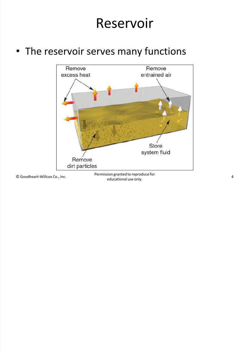
• The reservoir serves many functions
7/28/2019 Collection of slides for Hydraulic and Pneumatic systems
http://slidepdf.com/reader/full/collection-of-slides-for-hydraulic-and-pneumatic-systems 5/28
© Goodheart-Willcox Co., Inc. Permission granted to reproduce foreducational use only.
5
Reservoir
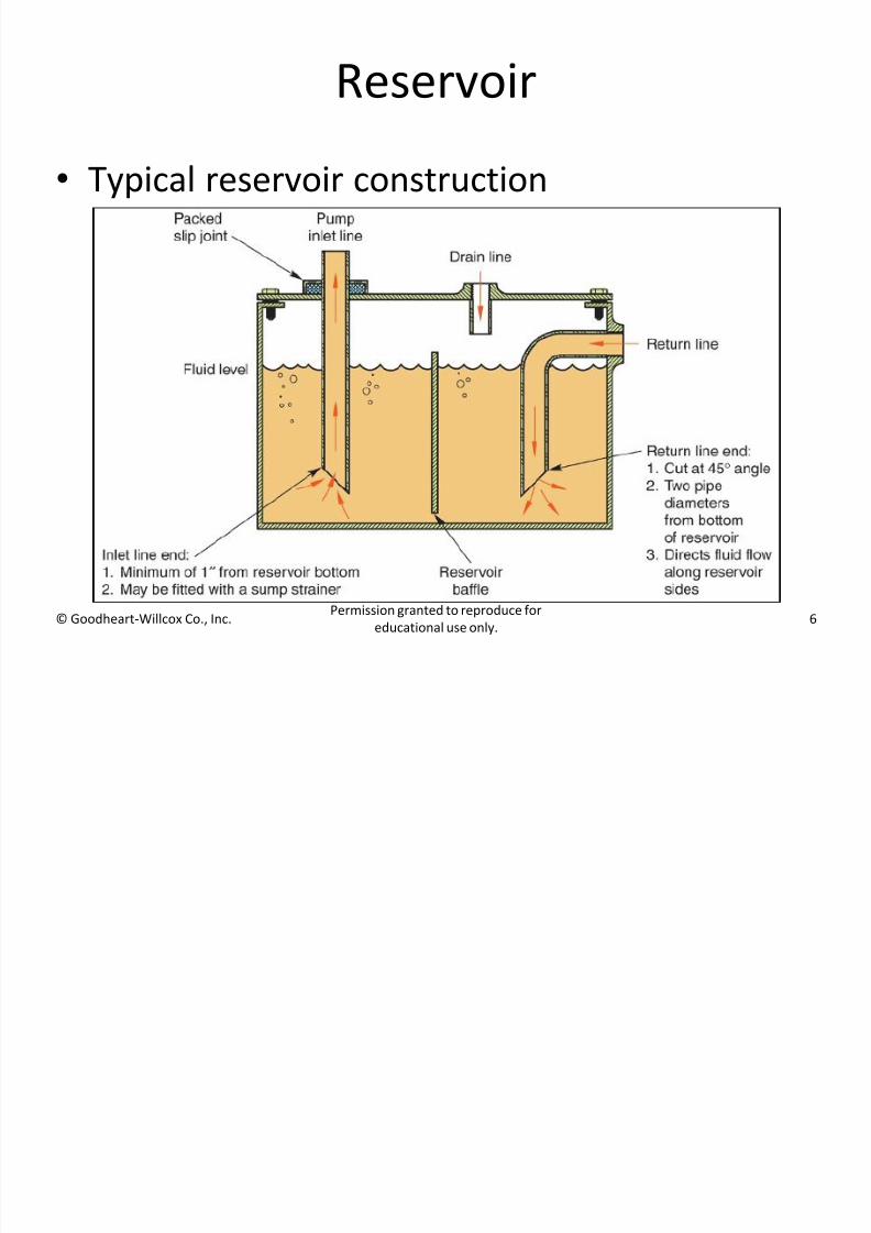
• Baffles are used in the interior of reservoirs to
direct flow to maximize the distance the fluid
must travel between the return line and the
pump inlet line
– Slows the movement of the fluid
– Increases cooling
– Increases separation of solid particles, air, andwater
7/28/2019 Collection of slides for Hydraulic and Pneumatic systems
http://slidepdf.com/reader/full/collection-of-slides-for-hydraulic-and-pneumatic-systems 6/28
© Goodheart-Willcox Co., Inc. Permission granted to reproduce foreducational use only.
6
Reservoir
• Typical reservoir construction
7/28/2019 Collection of slides for Hydraulic and Pneumatic systems
http://slidepdf.com/reader/full/collection-of-slides-for-hydraulic-and-pneumatic-systems 7/28
© Goodheart-Willcox Co., Inc. Permission granted to reproduce foreducational use only.
7
Conductors
• Pipe, tubing, and flexible hose are considered
basic conductors in a hydraulic system
7/28/2019 Collection of slides for Hydraulic and Pneumatic systems
http://slidepdf.com/reader/full/collection-of-slides-for-hydraulic-and-pneumatic-systems 8/28
© Goodheart-Willcox Co., Inc. Permission granted to reproduce foreducational use only.
8
Conductors
• Conductors must have:
– Adequate strength to withstand high system
pressures
– Low flow resistance to assure low energy loss
during system operation
– A design that allows economic installation and low
maintenance
7/28/2019 Collection of slides for Hydraulic and Pneumatic systems
http://slidepdf.com/reader/full/collection-of-slides-for-hydraulic-and-pneumatic-systems 9/28
© Goodheart-Willcox Co., Inc. Permission granted to reproduce foreducational use only.
9
Conductors
• Conductors must not only withstand normal
system operating pressure, but also hydraulic
shock pressures
• Shock pressures result from kinetic energy in
the system when:
– Directional control valves are shifted to reverse
the movement of a load or heavy machinemember
– Actuators encounter sudden load changes
7/28/2019 Collection of slides for Hydraulic and Pneumatic systems
http://slidepdf.com/reader/full/collection-of-slides-for-hydraulic-and-pneumatic-systems 10/28
© Goodheart-Willcox Co., Inc. Permission granted to reproduce foreducational use only.
10
Conductors
• Future maintenance must be carefully
considered when designing and installing
hydraulic system conductors to assure minimal
difficulty in removing components for service
7/28/2019 Collection of slides for Hydraulic and Pneumatic systems
http://slidepdf.com/reader/full/collection-of-slides-for-hydraulic-and-pneumatic-systems 11/28
© Goodheart-Willcox Co., Inc. Permission granted to reproduce foreducational use only.
11
Conductors
• Tubing:
– Is a relatively thin-walled, semirigid conductor
– Can be bent and shaped into lines that provide
good flow characteristics with a minimum of
visual clutter
7/28/2019 Collection of slides for Hydraulic and Pneumatic systems
http://slidepdf.com/reader/full/collection-of-slides-for-hydraulic-and-pneumatic-systems 12/28
© Goodheart-Willcox Co., Inc. Permission granted to reproduce foreducational use only.
12
Conductors
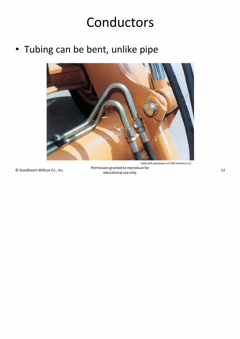
• Tubing can be bent, unlike pipe
Used with permission of CNH America LLC
7/28/2019 Collection of slides for Hydraulic and Pneumatic systems
http://slidepdf.com/reader/full/collection-of-slides-for-hydraulic-and-pneumatic-systems 13/28
© Goodheart-Willcox Co., Inc. Permission granted to reproduce foreducational use only.
13
Conductors
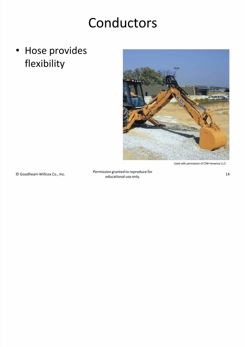
• Hose is a flexible conductor made up of:
– Inner tube to conduct the fluid
– Middle layer of reinforcing material for strength
– Outer protective coating to withstand abrasion
and abuse
7/28/2019 Collection of slides for Hydraulic and Pneumatic systems
http://slidepdf.com/reader/full/collection-of-slides-for-hydraulic-and-pneumatic-systems 14/28
© Goodheart-Willcox Co., Inc. Permission granted to reproduce foreducational use only.
14
Conductors
• Hose provides
flexibility
Used with permission of CNH America LLC
7/28/2019 Collection of slides for Hydraulic and Pneumatic systems
http://slidepdf.com/reader/full/collection-of-slides-for-hydraulic-and-pneumatic-systems 15/28
2005/2006 I. Hydraulic and Pneumatic Systems 15
Hydraulic fluids - tasks
They have the following primary tasks:
o Power transmission (pressure and motion
transmission)o Signal transmission for control
Secondary tasks:
o Lubrication of rotating and translatingcomponents to avoid friction and wear
o Heat transport, away from the location of heat
generation, usually into the reservoiro Transport of particles to the filter
o Protection of surfaces from chemical attack,especially corrosion
7/28/2019 Collection of slides for Hydraulic and Pneumatic systems
http://slidepdf.com/reader/full/collection-of-slides-for-hydraulic-and-pneumatic-systems 16/28
2005/2006 I. Hydraulic and Pneumatic Systems 16
Hydraulic fluids - requirements
Functional
o Good lubrication characteristics
o Viscosity should not depend strongly ontemperature and pressure
o Good heat conductivity
o Low heat expansion coefficient
o Large elasticity modulus
Economic
o Low price
o Slow aging and thermal and chemical stability long life cycle
7/28/2019 Collection of slides for Hydraulic and Pneumatic systems
http://slidepdf.com/reader/full/collection-of-slides-for-hydraulic-and-pneumatic-systems 17/28
2005/2006 I. Hydraulic and Pneumatic Systems 17
Hydraulic fluids - requirements (contd.)
Safety
o High flash point or in certain cases not
inflammable at all
o Chemically neutral (not aggressive at allagainst all materials it touches)
o Low air dissolving capability, not inclined tofoam formation
Environmental friendliness
o No environmental harmo No toxic effect
7/28/2019 Collection of slides for Hydraulic and Pneumatic systems
http://slidepdf.com/reader/full/collection-of-slides-for-hydraulic-and-pneumatic-systems 18/28
2005/2006 I. Hydraulic and Pneumatic Systems 18
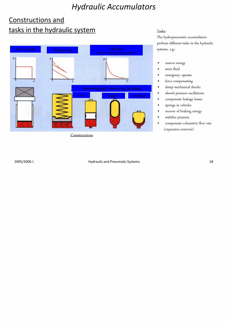
Hydraulic Accumulators
Constructions and
tasks in the hydraulic system Tasks:
The hydropneumatic accumulators
perform different tasks in the hydraulic
systems, e.g.:
Constructions
• reserve energy
• store fluid
• emergency operate
• force compensating
• damp mechanical shocks
• absorb pressure oscillations
• compensate leakage losses
• springs in vehicles
• recover of braking energy
• stabilize pressure
• compensate volumetric flow rate
(expansion reservoir)
With springWith weight With gas(hydropneumatic accumulator)
Separating part between gas and fluid
Piston Bladder Membrane
7/28/2019 Collection of slides for Hydraulic and Pneumatic systems
http://slidepdf.com/reader/full/collection-of-slides-for-hydraulic-and-pneumatic-systems 19/28
Properties of Compressed Air
• Availability
• Easily stored in large volumes
•
Simplicity in design and control• Provides linear and rotary movement
• Installation
• Low system cost due to low component cost
7/28/2019 Collection of slides for Hydraulic and Pneumatic systems
http://slidepdf.com/reader/full/collection-of-slides-for-hydraulic-and-pneumatic-systems 20/28
• Components have long working life
resulting in longer system reliability
• Environmentally friendly
• Safety issues are minimized e.g.. Fire
hazards; unaffected by overloads (actuators
stall or slip)• Pneumatic actuators in a system do not
produce heat (except for friction)
Properties of Compressed Air
7/28/2019 Collection of slides for Hydraulic and Pneumatic systems
http://slidepdf.com/reader/full/collection-of-slides-for-hydraulic-and-pneumatic-systems 21/28
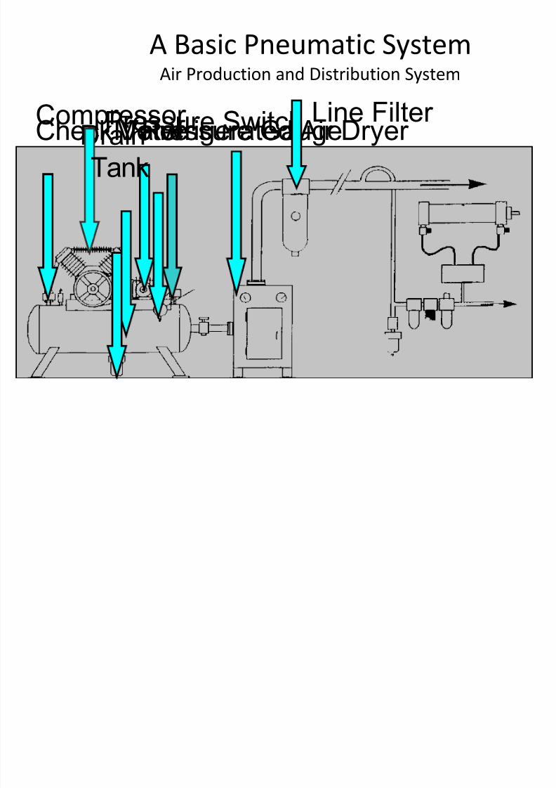
Pressure SwitchCompressor DrainCheck Valve
A Basic Pneumatic SystemAir Production and Distribution System
Motor
Tank
Pressure GaugeRefrigerated Air Dryer Line Filter
7/28/2019 Collection of slides for Hydraulic and Pneumatic systems
http://slidepdf.com/reader/full/collection-of-slides-for-hydraulic-and-pneumatic-systems 22/28
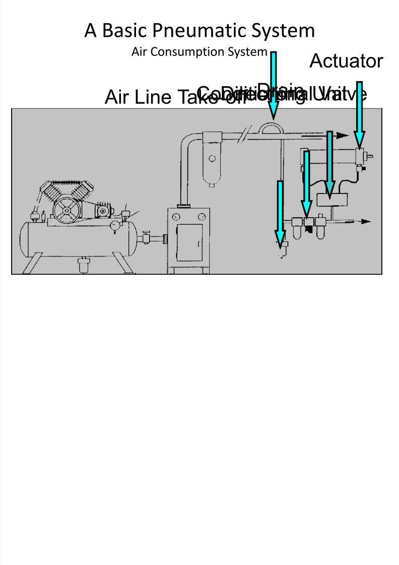
Directional Valve
A Basic Pneumatic SystemAir Consumption System
Air Line Take-off DrainConditioning Unit Actuator
7/28/2019 Collection of slides for Hydraulic and Pneumatic systems
http://slidepdf.com/reader/full/collection-of-slides-for-hydraulic-and-pneumatic-systems 23/28
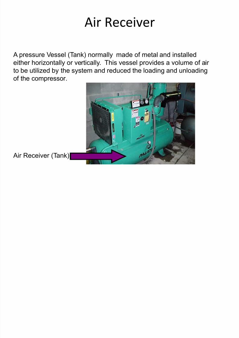
Air Receiver
A pressure Vessel (Tank) normally made of metal and installed
either horizontally or vertically. This vessel provides a volume of air
to be utilized by the system and reduced the loading and unloading
of the compressor.
Air Receiver (Tank)
7/28/2019 Collection of slides for Hydraulic and Pneumatic systems
http://slidepdf.com/reader/full/collection-of-slides-for-hydraulic-and-pneumatic-systems 24/28
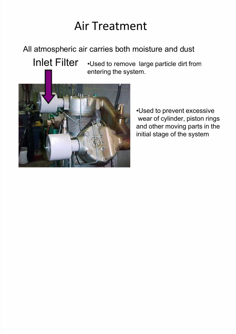
Air Treatment
All atmospheric air carries both moisture and dust
Inlet Filter •Used to remove large particle dirt from
entering the system.
•Used to prevent excessive
wear of cylinder, piston rings
and other moving parts in theinitial stage of the system
7/28/2019 Collection of slides for Hydraulic and Pneumatic systems
http://slidepdf.com/reader/full/collection-of-slides-for-hydraulic-and-pneumatic-systems 25/28
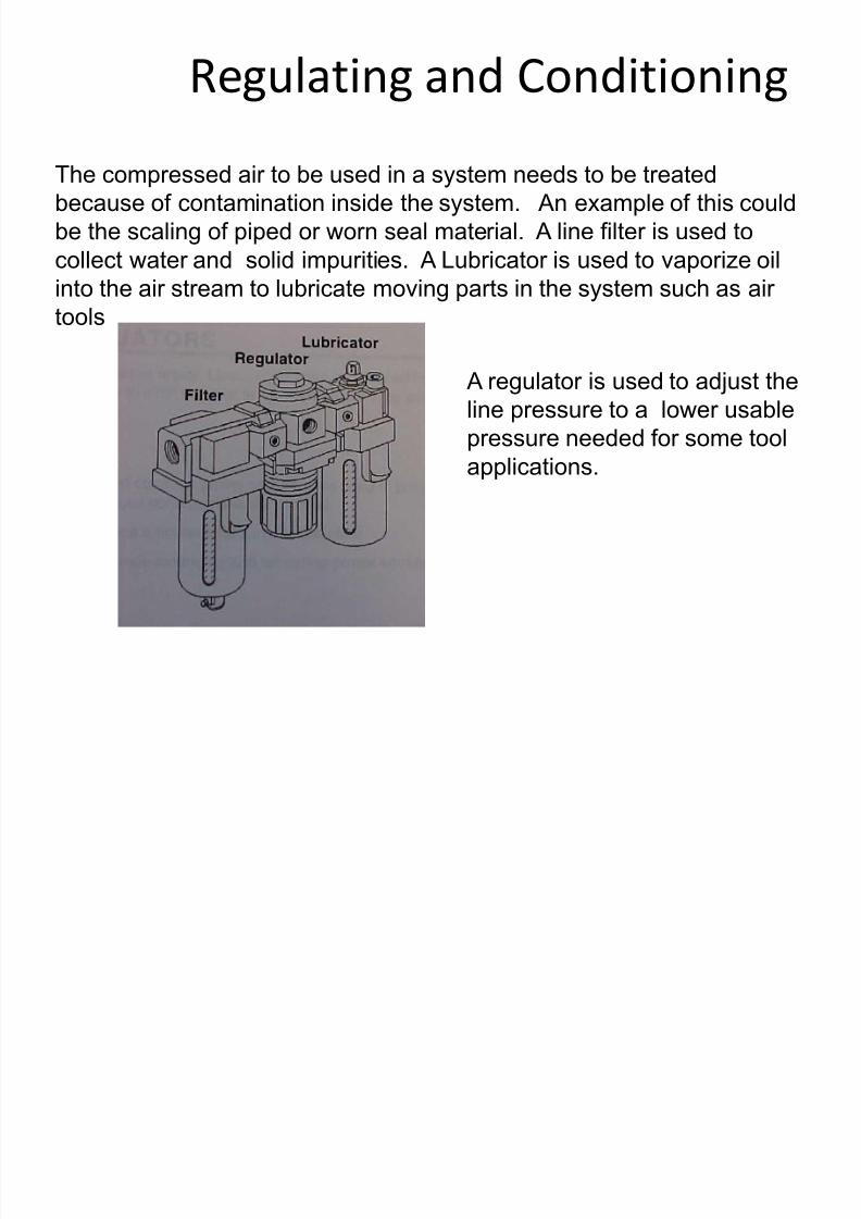
Regulating and Conditioning
The compressed air to be used in a system needs to be treated
because of contamination inside the system. An example of this could
be the scaling of piped or worn seal material. A line filter is used to
collect water and solid impurities. A Lubricator is used to vaporize oil
into the air stream to lubricate moving parts in the system such as air
tools
A regulator is used to adjust the
line pressure to a lower usable
pressure needed for some tool
applications.
7/28/2019 Collection of slides for Hydraulic and Pneumatic systems
http://slidepdf.com/reader/full/collection-of-slides-for-hydraulic-and-pneumatic-systems 26/28
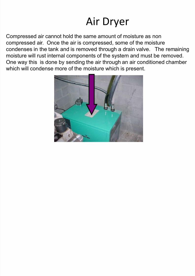
Air Dryer
Compressed air cannot hold the same amount of moisture as noncompressed air. Once the air is compressed, some of the moisture
condenses in the tank and is removed through a drain valve. The remaining
moisture will rust internal components of the system and must be removed.
One way this is done by sending the air through an air conditioned chamber
which will condense more of the moisture which is present.

7/28/2019 Collection of slides for Hydraulic and Pneumatic systems
http://slidepdf.com/reader/full/collection-of-slides-for-hydraulic-and-pneumatic-systems 27/28
Control Valves
Double Pressure Operated5 Port Valve
3 Port Pilot Valve 3 Port Pilot Valve
7/28/2019 Collection of slides for Hydraulic and Pneumatic systems
http://slidepdf.com/reader/full/collection-of-slides-for-hydraulic-and-pneumatic-systems 28/28
Actuators
The work done by a pneumatic actuator can be linear or rotary.
There are two basic types of linear cylinders
•Single-acting
•Double-acting