Embed Size (px)
Citation preview

N 9 1 - 1
PROPOSAL FOR A CONCEPTUALLY NEW COMPACTCOLLECTING OPTICS FOR POWERFUL LIGHT SOURCES
G. SaengerEuropean Space Research and Technology Centre (ESTEC) _
SUMMARY
Testing of a S/C under simulated outer space conditions is the best guarantee
for a successful missio_and for almost all of the parameters a good match (to
within a few %) may be reached in relevant test facilities (e.g. I.R.
background, earthshine and albedo radiatio_ residual atmosphere, intensity
stability, - distribution and spectrum of the solar radiation).
The collimation angle of the sun (32 arc min.) is, however, a drasticexception, here only ± ].5 to ± 2" are achieved which means a relative deviation by
nearly one order of magnitude.
The main reason for this is the presently used collecting optics havingunnecessary large diameters. Here a lens - mirror combination is proposed which
allows to reduce the diameter by nearly a factor of two and to achieve with the
present Xenon arc lamps a collimation angle of ± 0.8 °.
SCOPE
The best guarantee for a successful mission of a S/C project is a careful
testing on the ground, and since the S/C's became even more sophisticated requiring
more stringent specifications, one must assume that this remains also valid for thefuture.
The most important tests are the thermal balance tests; however, because of
the costly simulation of the solar radiation they are also the most expensive ones.
Present solar simulators show an intensity stability better than I% and a
uniformity of the intensity distribution in the test volume within ± 3 to ± 5%;
hence they match in this aspect to a high degree the real solar radiation. The
spectral intensity distribution is simulated actually by the Xenon spectrum,
sometimes the high Xenon peaks in the range from 0.8 to ].Oj_ are filtered toachieve a better match with the solar spectrum. Certainly there are numerous peaks
left which do not agree with the solar spectrum but because most materials do not
show a great selectivity within these spectral ranges, also this less good
simulation of the solar spectrum satisfies most customers so far (Fig. 1).
As for the collimation angle, there was for thermal balance testing neither a
serious demand nor is there a technical possibility to match the sun's collimation
angle (32 arc min.) to a similar degree as the previous parameters. The solar
simulators today have collimation angles of ± 1.5 to ± 2" in the test volume, hence
there is a deviation with the real one by a factor of 6 to 8.
357
https://ntrs.nasa.gov/search.jsp?R=19910009842 2018-05-13T17:36:58+00:00Z

For the near future, however, one has to expect a demand for a bettersimulation of the collimation angle, since on the light weight structures already
short shadowing and half shadowing effects will influence considerably temperature,temperature gradient and temperature profile as function of time and hence cause
thermal stress and/or degradation on these structures, which are a vital and
substantial part of the future S/C generation.
BOUNDARY CONDITIONS
The Liqht Source
Of course, when using a powerful light source of high plasma temperature,
there is no problem anticipated to achieve also a small collimation angle.
Considerable effort was spent in the past to develop powerful lamps, and the
outcome is the high power Xenon arc lamp with watercooled electrodes allowing an
arc power of 25 to 35 kW dependent on the lifetime requirements. This lamp reached
technical maturity, is commercially available, and for the near future no other
powerful light source is expected to replace this type of lamp.
The radiation intensity distribution of a Xenon arc is typically shown inFig. 2 and the polar radiation characteristics in Fig. 3 (here a Durotest lamp)
[Ref. I].
Because Xenon and solar spectrum show a fair agreement (Fig. I), also the
plasma temperature of the arc must be approximately the same as at the sun'ssurface. Therefore, a considerably better match of the collimation angle should be
achievable in case the collecting optics is properly adapted; even when considering
the light losses due to absorption and/or surface reflections of ,_,12% on each
optical element, an improvement by nearly a factor of three is feasible in case the
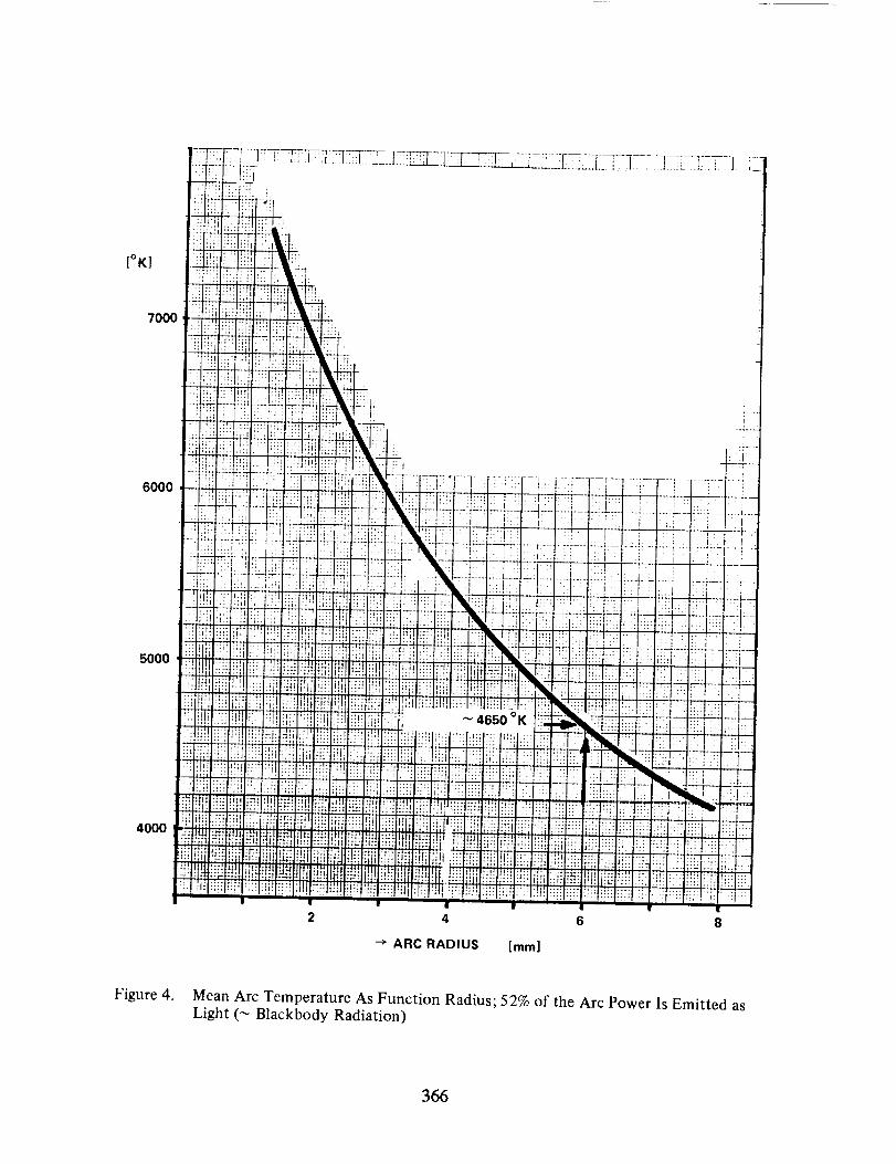
most intense part of the arc is used. The mean arc temperature as function of
radius is shown in Fig. 4.
The Projection System
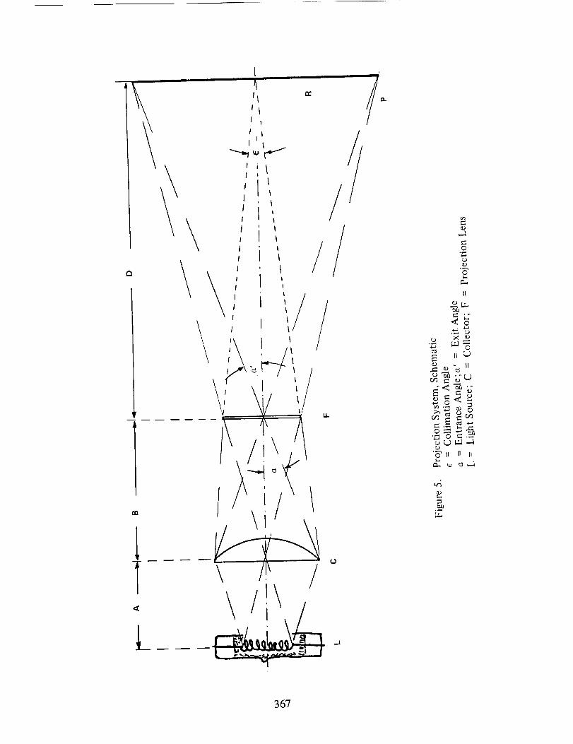
The principle of the projection system is illustrated in Fig. 5. The condensor- or collecting mirror - (C) directs the more or less spherically emitted light ofthe light source towards the projection lens (F) and the projection lens focussesthe condensor plane into the reference plane (P). Optimum performance is obviouslyachieved in case the condensor is designed such that also the light source isfocussed onto the projection lens since then there is no loss of light due to spillover and the lens may have minimum diamter. Naturally one may add in the same wayanother optical element (e.g. field lens) with the consequence that not thecondensor plane but the light source (via an image) is focussed in the referenceplane, of course also with the corresponding intensity distribution (Ref. 2, 3, 4).
In order to achieve a high intensity, one should keep the radius (R) of thereference plane (P) as small as possible which requires a small exit angle ((:X,');
this exit angle, however, cannot be made smaller than the entrance angle (_)because then part of the collector would not be covered, hence severe light losses
would be the consequence.
358

On the other hand is the collimation angle (_) given by the ratio of the
projection lens dia_ter to the distance of the reference plane (D). Thus for a
small collimation at a high intensity level (_ small beam diameter) one should
keep both exit (= entrance) angle and the image of the light source as small as
possible. The first demand means a small diameter of the collecting optics, the
second a small but intense light source (and, as mentioned before, the best one can
use is the high power Xenon arc lamp).
When using such a Xenon lamp one could capture and lead the emitted light to
the field lens plane e.g. by means of optical fibres, clustered around the Xenon
bulb; the spheric liflht emitting surface (4._oR 2 bulb) is then converted into a
circular plane (]_C.RL plane) with the same exit angle of the light, in other words
the smallest achievable diameter of the collecting optics is twice the diamter of
the light source:
R plane = 2.R bulb
The Xenon lamps have a bulb diameter of 13_ 14 cm, therefore it seems likelyto reduce the diameter of the collecting optics from presently 56 - 60 cm to
30 cm, which means an improvement by nearly a factor of two.
Since in addition the polar radiation as well as the intensity across the arc
is highly non-uniform, a further improvement is feasible when only the mostintensive parts are used; of course this will be on account of the overall
efficiency.
Review of Presently Used Optics
The parabolic reflector
The well-known and by far mostly used parabolic (or shaped close to a
parabola) mirror is mechanically the simplest solution; from the optical point of
view it is, however, a bad one. It is actually an optical element where the focal
length varies.
Close to the optical axis is the focal length short and increases steadily for
larger mouth angles (see Fig. 6). Consequently the rays of small entrance angle
(close to the optical axis) produce a large image in the field lens plane and vice
versa produce the l_ght rays of large entrance angle (_ at large mouth angles)
small images; thus, in order to capture a high percentage of the emitted light with
a parabolic mirror, both a large entrance angle and a large image of the light
source in the field lens plane results. In addition the percentage of captured
light for large radii is relatively low (_ per cm radius), see figs. 6, 7.
Of course, one could use a small spherical secondary mirror so that the light
leaving the upper part of the bulb (to the anode) will be reflected back through
the arc, hence a considerably smaller mouth angle (_ smaller collector diameter)would result. The efficiency of such a mirror is, however, rather low; according to
Kirchhoff's law a good emitter is also a good absorber. We measured at ESTEC on our
HBF3 space chamber when operating the solar simulator with a secondary mirror, a
contribution of only 15_20%.
359

The Koehler Collector
The less applied Koehler integrator (Ref. 5) is mechanically more complicated,
from the optical point of view, however, a better solution; actually two lens +
deflecting mirror arrays (2 x 7) are clustered around the light source (Fig. 8).
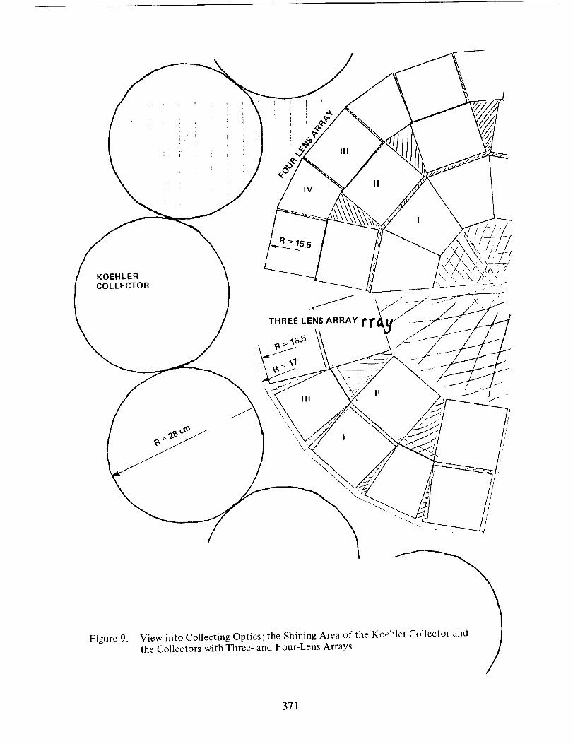
Since the distance to the light source centre is for all lenses the same, all theindividual arc images are of the same dimensions. When looking from the field lens
plane into the collector along the optical axis, one will see a shining area
composed by 2 x 7 circular areas arranged in a circle around the Xenon lamp
(Fig. 9).
It is a pity that from the total cross-sectional area only the outer part isused, making the entrance angle unnecessary large. Of course one could place the
upper deflecting mirrors closer to the centre, but there is no way to reduce the
overall diameter since the lower deflecting mirrors will have to be kept in their
position. (When using instead of a 2 x 7 lens array one of 2 x 6 it seems feasible
to achieve a hexagon arrangement which would have a higher package density for
clustering of lamp units.
Naturally various constructions are possible to fill up the gap in the
cross-sectional area using additional deflecting mirrors; however, all thesesolutions will be highly complex and costly and do not allow standardisation of a
lamp module.
COMPACT COLLECTING OPTICS
General Considerations
As outlined in the foregoing paragraph the requirements for achieving a small
collimation angle boil down to:
I .
2.
3.
To capture the light leaving the light source as soon as possible, that means
to align it parallel and avoid further expansion of the light beams.
To use optical elements of identical focal length.
To convert the spherical light emitting area into a circular or hexagonal
plane of preferably the same area.
The Koehler integrator meets only the first two requirements; on account of
the third one instead it was designed relatively simple; the lenses are identical,
they have both the same focal length and the same diameter, hence also the lens
plane may be superimposed and projected into the reference plane because the
optical orientation is ruled out, and since the intensity distribution across the
lens plane is considerably more uniform than across the arc image one may achieve a
fair intensity distribution without integrator or mixer.
The fact that the arc images are of the same dimensions (requirement 2) allows
to make effective use of the most intense part of the arc (above the cathode tip,
Fig. 2). In Fig. 10 the emitted light is shown as function of the arc diameter
used, and obviously it is unfortunate to go for more than _6 mm arc diameter,since here already_66% of the emitted light is capture_ and for larger radii the
gain of light is substantially reduced.
360

Three Lens Array
In order to reduce the overall diameter of the collecting optics one has to
disregard the advantages of the simplicity of the Koehler integrator, since only
with a third lens array one may make use of the inner parts of the circular plane.
The beams of the equatorial lens array (Fig. 11) may be deflected by the innercircle of deflecting mirrors, whilst the beams of the upper (anode) and lower
(cathode) lens array will be deflected by mirrors positioned at the same radius,
one in the gap of the other, naturally at different height. The diameter of such acollector unit would be_33 cm and hence only 60% of the parabolic reflector. The
amount of captured light is 80 %, which is approximately the same as for the
parabolic reflector (Ref. 4). The light losses, however, are higher due to spill
over and surface reflections on the lenses. A detailed breakdown of the light
losses is given in Table I, see also Fig. 11 a, b and Fig. 9.
The gaps between the deflecting mirrors of the inner circle may be used for
the supporting structure for lenses and mirrors, thus they are not only a
disadvantage. Compared with the Koehler integrator this design has considerably
more elements and is more complicated. However, the lenses have a smaller openingrequiring less refractivity and may therefore be provided with normal spherical
surfaces which is substantially cheaper than for parabolic ones.
Considering the arc utilisation, the light losses, the diameter of the
collecting optics and the optimum arc image, it should be possible to achieve at
I S.C. level with a 25 kW lamp a collimation angle of ± I°.
Four Lens Array
The three lens array leaves mainly two fields open for improvement:
I .
2.
the inner part of the light emitting area is not used (smaller than bulb
diameter)
the spill over losses are relatively high.
Naturally, when more optical elements are used to convert the spherically
light emitting surface into a circular plane, also a higher package density is
possible. However, when using more optical elements, also the spill over losseswill increase, besides the fact that the arrangement will also become more
complicated and more costly. A four lens array seems to be sufficient to achieve
the desired improvements mentioned without complicating the whole arrangement too
much. The main difference compared with the three lens array is that on the top (to
the anode) two deflecting mirrors are required (Fig. 12 a, b and Fig. 9).
The breakdown of the light losses and the resulting overall efficiency isgiven in table 2. For I S.C. level this should allow a collimation angle of ± 0.8 °,
(only the lower intense part of the arc is used) with sufficient margin (Fig.13).
CONCLUDING REMARKS
In general one may say that the high power Xenon arc lamps allow to achieve a
smaller collimation angle in case a properly adapted collecting optics is used. The
widely used parabolic reflector is for this purpose not applicable.
361

Certainly the proposed collecting optics is very expensive due to the highnumber of optical elements and beyond that it will be a total loss in case of alamp failure (explosion). On the other hand one should keep in mind that most lampexplosions occur after shutdown (during cooldown of the quartz bulb) and maytherefore be avoided in case the Xenon gas is frozen out after operation in a smallstainless steel bottle which is cooled down to LN2 temperature and then valved off;thus in case of a thermal crack there is no longer a gas pressure in the quartzbulb (Ref. 1).
Another critical issue is the cooling of the quartz bulb, and the question maycome up to mind whether the closely clustered lens arrays are not a seriousimpedance for the cooling. Considering, however, the fact that most critical forcooling if the upper part of the bulb (above the equator) where turbulent flowdominates, the contrary is to be expected: the lens arrays force the cooling gas tokeep in close touch with the quartz bulb and to guarantee a steady and uniformcooling flow also above the equator.
Obviously there is a real possibility to reduce the risk of lamp failure
(explosion) drastically and to avoid major damage during operation. Irrespective,such a collecting optics will be a costly investment and will contribute to the
besides expensive space simulation facilities. Compared, however, with a single
major S/C project the costs are often within the contingency; reliability and
accuracy would be considerably improved.
OTHER APPLICATIONS
The proposed collecting optics may of cause be used for any other light
source. Compared with the parabolic reflector it is much more complicated; however,
the high number of optical elements allow besides the compactness:
I •
2.
3.
a better directivity of the beam
a better uniformity of the intensity in the reference planeto illuminate an area of special shape by individual adjustment of the
deflecting mirrors.
In the car industry there is in recent years a demand for more compact
collecting optics; here the high production number would reduce the production
costs per unit substantially.
REFERENCES
•
•
.
4.5.
W.E. Thouret, FIES, J. Leyden, H.S. Strauss, G. Shaffer, H. Kee
"20 to 30 kW Xenon Compact Arc Lamps for Searchlights and Solar
Simulators", Journal of IES, Oct. 1972
Eddy, R.P., "Design and Construction of the 15-Foot Beam Solar Simulator
SS 15 B", Technical Report 32-1274, Jet Propulsion Laboratory, Pasadena,
Calif., Oct. 1, 1968.
Harrell, J.W. and Argoud, M.J., "The 25-Foot Space Simulator at the Jet
Propulsion Laboratory, Pasadena, Calif., Oct. 15, 1969.
Dr. Frey, IABG, Ottobrunn, FRG, private communication
P. Dejong, "Les simulateurs Spatiaux", Revue G_n_rale de l'Electricit_,October 1966, t. 75, no. 10
362

TABLE I: III LENS ARRAY, EFFICIENCY OF COLLECTOR
(48% of emitted light, 24.9% of arc power)
Lens array I
Lens array II
Lens array Ill
ANGLE
50- 75
75-105
105-135
INTENSITY
RANGE
%
8 - 30
30 - 61
61 - 88
LOSSES ON LENSES
REFLECTION
%
10
10
10
OVER-
SPILL %
3.3
3.3
3.3
ILOSSES ON MIRRORS
REFLECTION
%
15
15
15
OVER-SPILL %
25
5
30
EFFICIENCYPER LENSARRAY
%
12.2
21.8
14
TABLE II: IV LENS ARRAY, EFFICIENCY OF COLLECTOR
(59% of emitted light, 30.6% of arc power)
Lens array I
Lens array II
Lens array III
Lens array IV
ANGLE
45- 70
70- 95
95-120
120-145
INTENSITY
RANGE
%
5 -22.5
22.5-48.5
48.5-75
75 -93.5
LOSSES ON LENSES
REFLECTION
%
I0
I0
I0
IO
OVER-
SPILL %
3.8
3.3
3.3
3.8
LOSSES ON MIRRORS
REFLECTION
%
2x15
15
15
15
lOVER-SPILL %
20
5
I0
20
EFFICIENCYPER LENSARRAY
%
10.15
20.3
17.6
]0.9
363

00
!
00
IN
00
SIlNR "'13t:1
Q
0
E(,-
..rl-
zI.U
I,Ll
>
E
E
E
<.J
©
t,,...
©
S¢.-,
©
.-2
364

oo oo oo
_ _.-\_. / ........,,,
tl.
3GONV =IQOH.LVO
h..o
c_
_o=go_c'J }-_
cZ_
•--_ hi)
(L)
UJ
0Z
0 0O 0 0
o
o°_
_o_
E_o
Lu
365
[°K]
7000
6000
5000
4000
4650°K
12 4 6 8
--> ARC RADIUS [mm]
Figure 4. Mean Arc Temperature As Function Radius; 52% of the Arc Power Is Emitted as
Light (_ Blackbody Radiation)
366
I
I\
i U=
\,'!',I\ li\
ZQ-,
II
•_,_ _"6'ii11ii
367

IMAGES OF THE ARC IN
THE FIELD LENS PLANE
1606 140 °
100
[%]
80
60
4O
2O
Figure 6. Parabolic Reflector, Schematic
368

0 _ 0 0 0r_o:3::I--
_J
<
'U
0
0°_
LU
oc)
0
L;
0J
0
_D
co
_J
LU
369
_,,_,_,_H_.PAGE ISOF POOR QUALITY

LENS
MIRROR J =i i
MIRROR
STRUCTURE
Figure 8. The Koehler Collector of BBT; 2 x 7 Lens-Mirror Combination
370
KOEHLERCOLLECTOR
\
\
Figure 9.View into Collecting Optics; the Shining Area of the Koehl
the Collectors with Three- and Four-Lens Arrays
371

100
[%]
8O
60
OPTIMUM ¢ AT _ 6mm,CAPTURED LIGHT ,_ 66%
40
20
5 10
ARC DIAMETER [mm]
15
Figure 10. Light Output of a Xenon Lamp a Function of Arc Diameter Used
372

4--
\\
Li
ill
0I--
Z
IIi
0(IIIII 1
/
i |
373

0
/
/
/
/
/ox
¢)
E
II
©
.2,
©
o
<q
374

SECOND DE F LECTI NGMIRROR
!
I A
DEFLECTINGMIRRORS
B
D
Figure 13. General View of Four-Lens Array Collector
375


SESSION IX
UNIQUE TESTS AND REQUIREMENTS
PRECEDING PAGE BLANK NO'f FILMED