Embed Size (px)
Citation preview

1 Copyright © 2006 by ASME
Proceedings of OMAE’06: 25th International Conference on Offshore Mechanics and Arctic Engineering
June 4-9, 2006, Hamburg, Germany
OMAE2006-92168
COLLAPSE ARRESTORS FOR DEEPWATER PIPELINES: FINITE ELEMENT MODELS AND EXPERIMENTAL VALIDATIONS FOR DIFFERENT CROSS-OVER MECHANISMS
Rita G. Toscano Center for Industrial Research, TENARIS
Argentina
Luciano O. Mantovano Center for Industrial Research, TENARIS
Argentina
Pablo Amenta Center for Industrial Research, TENARIS
Argentina
Roberto Chareau Center for Industrial Research, TENARIS
Argentina
Daniel Johnson
Center for Industrial Research, TENARIS
Argentina
Andrea Assanelli Center for Industrial Research, TENARIS
Argentina
Eduardo N. Dvorkin Center for Industrial Research, TENARIS
Argentina ABSTRACT
Using finite element models it is possible to determine the cross-over external pressure of different pipeline arrestor designs. In this paper these finite element models are discussed and validated by comparing their results with experimental determinations. The flipping and flattening cross-over mechanisms are considered in the experimental validation of the numerical models.
INTRODUCTION Deepwater pipelines are normally subjected to external
pressure and bending. They fail due to structural collapse when the external loading exceeds the pipes collapse limit surface. For seamless steel pipes, the influence on this limit surface of manufacturing imperfections has been thoroughly studied using finite element models that have been validated via laboratory full-scale tests [1-6].
If by accident the collapse is initiated at a certain location, the collapse is either restrained to the collapse initiation section or it propagates along the pipeline, being this second alternative the most detrimental one for the pipeline integrity [7]. Since the external collapse propagation pressure is usually quite low in comparison with the external collapse pressure, it is necessary to build in the pipeline spaced reinforcements, usually steel rings, to act as arrestors for the collapse propagation.
Two different buckle arrestor cross-over mechanisms were identified in the literature: flattening and flipping. The occurrence of either cross-over mechanism is determined by the geometry of the pipes and of the arrestors [8]. In this paper we develop finite element models to analyze the collapse pressure, collapse propagation pressure and cross-over pressure of pipelines and we present an experimental validation for these models.
EXPERIMENTAL RESULTS USING SEAMLESS STEEL PIPES
Few experimental results are available in the literature for the cross-over of integral ring buckle arrestors under external pressure on large diameter carbon steel pipes [9, 10]. Most of the available experimental results correspond to stainless steel and small diameter steel pipes [8, 11-14]. Therefore this paper adds to the available technical literature in a range where more information can be useful.
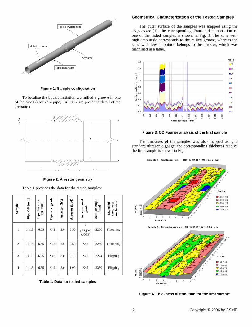
The purpose of our laboratory tests was to determine the equilibrium path for the assembly (pipe + arrestor + pipe) under external pressure; and from it determine the collapse pressure, and the cross-over pressure. Fig. 1 shows the sample configuration.
2 Copyright © 2006 by ASME
Arrestor
Pipe upstream
Pipe downstream
Milled groove
Arrestor
Pipe upstream
Pipe downstream
Milled groove
Figure 1. Sample configuration
To localize the buckle initiation we milled a groove in one of the pipes (upstream pipe). In Fig. 2 we present a detail of the arrestors:
I.D.
La
D
h
t
I.D.
La
D
h
t
Figure 2. Arrestor geometry
Table 1 provides the data for the tested samples:
Sam
ple
Pipe
OD
[mm
]
Pipe
thic
knes
s (t
) [m
m]
Pipe
stee
l gra
de
Arr
esto
r (h
/t)
Arr
esto
r (L
a/D
)
Arr
esto
r st
eel
grad
e
Sam
ple
leng
th
[mm
]
Exp
ecte
d
cros
s-ov
er
mec
hani
sm
1 141.3 6.55 X42 2.0 0.50 6
(ASTM A-333)
2250 Flattening
2 141.3 6.55 X42 2.5 0.50 X42 2250 Flattening
3 141.3 6.55 X42 3.0 0.75 X42 2274 Flipping
4 141.3 6.55 X42 3.0 1.00 X42 2330 Flipping
Table 1. Data for tested samples
Geometrical Characterization of the Tested Samples The outer surface of the samples was mapped using the
shapemeter [1]; the corresponding Fourier decomposition of one of the tested samples is shown in Fig. 3. The zone with high amplitude corresponds to the milled groove, whereas the zone with low amplitude belongs to the arrestor, which was machined in a lathe.
p
0.0
0.2
0.4
0.6
0.8
1.0
1.2
1.4
1.6
-28
160
348
536
725
913
1101
1289
1477
1665
1854
2042
2230
Axial position [mm]
Mo
de a
mp
litu
de
[m
m]
12
11
10
9
8
7
6
5
4
3
2
Mode
Figure 3. OD Fourier analysis of the first sample The thickness of the samples was also mapped using a
standard ultrasonic gauge; the corresponding thickness map of the first sample is shown in Fig. 4.
1 2 3 4 5 6 7 8A
AB
B
BC
C
CDD
DEE
EFF
FGG
GHH
HII
IJJ
JKK
KLL
6.256.406.556.706.857.00
Wt
[mm
]
Generatrix
Section
Sample 1 - Upstream pipe - OD : 5 9/16" Wt : 6.55 mm
6.85-7.00
6.70-6.85
6.55-6.70
6.40-6.55
6.25-6.40
1 2 3 4 5 6 7 8MN
N
NO
O
OP
P
PQ
QQR
RRS
SST
TTU
UUV
VVW
WWX
6.256.406.556.706.857.00
Wt
[mm
]
Generatrix
Section
Sample 1 - Downstream pipe - OD : 5 9/16" Wt : 6.55 mm
6.85-7.00
6.70-6.85
6.55-6.70
6.40-6.55
6.25-6.40
Figure 4. Thickness distribution for the first sample

3 Copyright © 2006 by ASME
Mechanical Characterization of the Tested Samples
For all the pipe and arrestor materials we determined: • True stress – true strain curves (longitudinal tensile
tests since the thickness of the pipes was too small for hoop samples) • Hoop residual stresses (evaluated using slit ring tests)
Sample Max. residual stress / yield stress
1 0.39 2 0.47 3 0.47 4 0.49
Table 2. Measured residual stresses
Experimental facility
In Fig. 5 we present a scheme of the experimental set-up. In order to measure the internal volume variation perforated end-caps were welded to the pipes. Each specimen was completely filled with water before the beginning of the test. From the hole in one of the end caps the water was directed to a container connected to a load cell. The load variation in the load cell is proportional to the displaced water.
Figure 5. Experimental set-up
Experimental results Typical experimental results are shown in Fig. 6.
Sample 1: Pressure vs. Volume
0
5
10
15
20
25
30
0.00 0.05 0.10 0.15 0.20 0.25 0.30 0.35 0.40 0.45 0.50
Volume variation
Exte
rnal
Pre
ssu
re [
MP
a]
Experimental
Pco_exp: 11.89 MPa
Pcol_exp: 29.03 MPa
(a) First sample: Flattening mode
Sample 3: Pressure vs. Volume
0
5
10
15
20
25
30
0.00 0.05 0.10 0.15 0.20 0.25 0.30 0.35 0.40 0.45 0.50
Volume variation
Exte
rnal
Pre
ssu
re [
Mp
a]
ExperimentalPcol_exp: 26.53 MPa
Pco_exp: 25.24 MPa
(b) Third sample: Flipping mode
Figure 6. Experimentally determined p-V curves
We use:
volumeinsideOriginalvolumeinsideiationVolume Δ
=var (1)
THE FINITE ELEMENT MODELS
For the numerical simulation of the crossing of an integral ring arrestor by a quasi-statically propagating buckle, we developed a finite element model using the MITC4 shell element in the ADINA general-purpose code [15 -16].
The numerical model was developed using a material and geometrical nonlinear formulation, taking into account large displacements/rotations but small strains [17] and it incorporates the following features:
• Geometry as described by the O.D. mapping and by the thickness distribution that was acquired for each sample as reported above.
• Von Mises elasto plastic material model with isotropic multilinear hardening.
• Hoop residual stresses. • Contact elements on the pipe inner surface in order to
prevent its inter-penetration in the post collapse and propagation regime.
• Nonlinear equilibrium path tracing via the algorithm developed in Ref. [18].
• Residual stresses modeled with the technique discussed in [1].
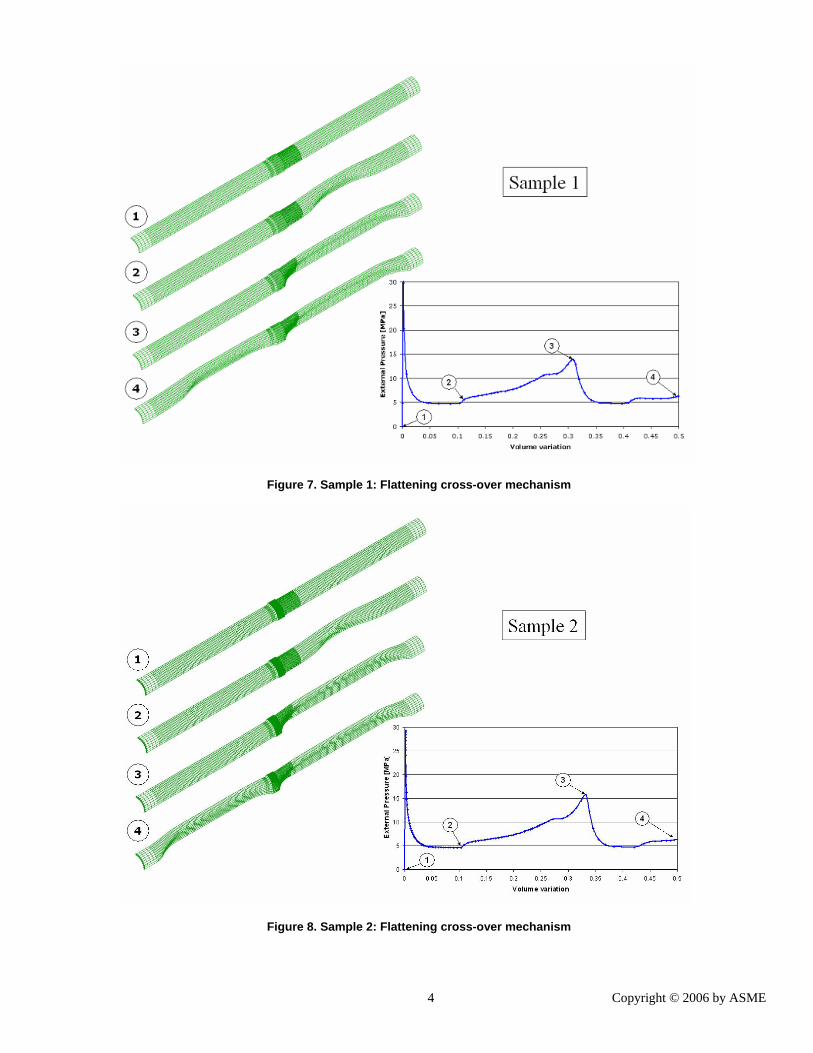
Identifying the different cross-over mechanisms
In Figures 7 and 8 we present the finite element predicted deformed shapes for a (pipes – arrestor) system exhibiting a flattening cross-over mechanism and in Figs. 9 and 10 we show the predicted deformed shapes for a system presenting a flipping cross-over mechanism.
4 Copyright © 2006 by ASME
Figure 7. Sample 1: Flattening cross-over mechanism
Figure 8. Sample 2: Flattening cross-over mechanism

5 Copyright © 2006 by ASME
Figure 9. Sample 3: Flipping cross-over mechanism
Figure 10. Sample 4: Flipping cross-over mechanism
6 Copyright © 2006 by ASME
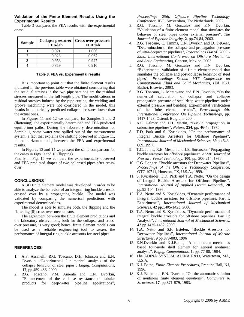
Validation of the Finite Element Results Using the Experimental Results
Table 3 compares the FEA results with the experimental ones:
Sample Collapse pressure: FEA/lab
Cross-over pressure: FEA/lab
1 0.921 1.006 2 0.923 0.967 3 0.953 0.927 4 0.859 0.910
Table 3. FEA vs. Experimental results
It is important to point out that the finite element results
indicated in the previous table were obtained considering that the residual stresses in the two pipe sections are the residual stresses measured in the full length pipe. The modifications in residual stresses induced by the pipe cutting, the welding and groove machining were not considered in the model, this results in numerically predicted collapse pressures lower than the actual ones.
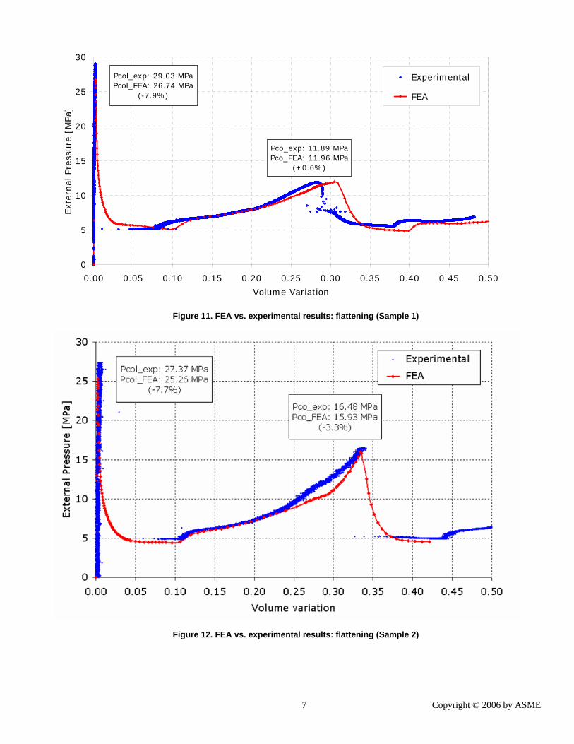
In Figures 11 and 12 we compare, for Samples 1 and 2 (flattening), the experimentally determined and FEA predicted equilibrium paths. During the laboratory determination for Sample 1, some water was spilled out of the measurement system, a fact that explains the shifting observed in Figure 11, in the horizontal axis, between the FEA and experimental results.
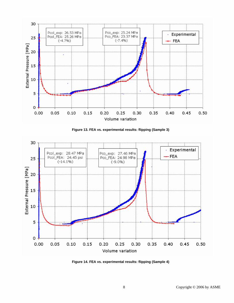
In Figures 13 and 14 we present the same comparison for the cases in Figs. 9 and 10 (flipping). Finally in Fig. 15 we compare the experimentally observed and FEA predicted shapes of two collapsed pipes after cross-over.
CONCLUSIONS A 3D finite element model was developed in order to be
able to analyze the behavior of an integral ring buckle arrestor crossed over by a propagating buckle. The model was validated by comparing the numerical predictions with experimental determinations.
The model is able to simulate both, the flipping and the flattening [8] cross-over mechanisms.
The agreement between the finite element predictions and the laboratory observations, both for the collapse and cross-over pressure, is very good; hence, finite element models can be used as a reliable engineering tool to assess the performance of integral ring buckle arrestors for steel pipes.
REFERENCES 1. A.P. Assanelli, R.G. Toscano, D.H. Johnson and E.N.
Dvorkin, “Experimental / numerical analysis of the collapse behavior of steel pipes”, Engng. Computations, 17, pp.459-486, 2000.
2. R.G. Toscano, P.M. Amenta and E.N. Dvorkin, “Enhancement of the collapse resistance of tubular products for deep-water pipeline applications”,
Proceedings 25th. Offshore Pipeline Technology Conference, IBC, Amsterdam, The Netherlands, 2002.
3. R.G. Toscano, M. Gonzalez and E.N. Dvorkin, "Validation of a finite element model that simulates the behavior of steel pipes under external pressure", The Journal of Pipeline Integrity, 2, pp.74-84, 2003.
4. R.G. Toscano, C. Timms, E.N. Dvorkin and D. DeGeer, "Determination of the collapse and propagation pressure of ultra-deepwater pipelines", Proceedings OMAE 2003 - 22nd. International Conference on Offshore Mechanics and Artic Engineering, Cancun, Mexico, 2003
5. R.G. Toscano, M. Gonzalez and E.N. Dvorkin, “Experimental validation of a finite element model that simulates the collapse and post-collapse behavior of steel pipes”, Proceedings Second MIT Conference on Computational Fluid and Solid Mechanics, (Ed. K.-J. Bathe), Elsevier, 2003.
6. R.G. Toscano, L. Mantovano and E.N. Dvorkin, “On the numerical calculation of collapse and collapse propagation pressure of steel deep water pipelines under external pressure and bending: Experimental verification of the finite element results”, Proceedings 4th. International Conference On Pipeline Technology, pp. 1417-1428, Ostend, Belgium, 2004.
7. A.C. Palmer and J.H. Martin, “Buckle propagation in submarine pipelines”, Nature, 254, pp. 46-48, 1975.
8. T.D. Park and S. Kyriakides, "On the performance of Integral Buckle Arrestors for Offshore Pipelines", International Journal of Mechanical Sciences, 39 pp.643-669, 1997.
9. T.G. Johns, R.E. Mesloh and J.E. Sorenson, “Propagating buckle arrestors for offshore pipelines”. ASME Journal of Pressure Vessel Technology, 100, pp. 206-214, 1978.
10. C.G. Langer, “Buckle arrestors for Deepwater Pipelines”, Proceedings of the Offshore Technology Conference, OTC 10711, Houston, TX, U.S.A., 1999.
11. S. Kyriakides, T.D. Park and T.A. Netto, "On the design of Integral Buckle Arrestors for Offshore Pipelines", International Journal of Applied Ocean Research, 20 pp.95-104, 1998.
12. T.A. Netto and S. Kyriakides, “Dynamic performance of integral buckle arrestors for offshore pipelines. Part I: Experiments”, International Journal of Mechanical Sciences, 42 pp.1405-1423, 2000
13. T.A. Netto and S. Kyriakides, “Dynamic performance of integral buckle arrestors for offshore pipelines. Part II: Analysis”, International Journal of Mechanical Sciences, 42 pp.1425-1452, 2000
14. T.A. Netto and S.F. Estefen, “Buckle Arrestors for Deepwater Pipelines”, International Journal of Marine Structures, 9 pp.873-883, 1996
15. E.N.Dvorkin and K.J.Bathe, “A continuum mechanics based four-node shell element for general nonlinear analysis”, Engng. Computations, 1, pp. 77-88, 1984.
16. The ADINA SYSTEM, ADINA R&D, Watertown, MA, U.S.A.
17. K.J. Bathe, Finite Element Procedures, Prentice Hall, NJ, 1996.
18. K.J. Bathe and E.N. Dvorkin, “On the automatic solution of nonlinear finite element equations”, Computers & Structures, 17, pp.871-879, 1983.
7 Copyright © 2006 by ASME
0
5
10
15
20
25
30
0.00 0.05 0.10 0.15 0.20 0.25 0.30 0.35 0.40 0.45 0.50
Volume Variation
Ext
ernal
Pre
ssure
[M
Pa]
Experimental
FEA
Pcol_exp: 29.03 MPaPcol_FEA: 26.74 MPa
(-7.9%)
Pco_exp: 11.89 MPa Pco_FEA: 11.96 MPa
(+0.6%)
Figure 11. FEA vs. experimental results: flattening (Sample 1)
Figure 12. FEA vs. experimental results: flattening (Sample 2)
8 Copyright © 2006 by ASME
Figure 13. FEA vs. experimental results: flipping (Sample 3)
Figure 14. FEA vs. experimental results: flipping (Sample 4)

9 Copyright © 2006 by ASME
(a) Sample 2 – flattening
(b) Sample 3 - flipping
Figure 15. Experimentally observed and FEA predicted shapes of collapsed pipes after cross-over.


![Chapter Propagation Buckling of Subsea Pipelines and Pipe ...investigates the effect of corrosion in the propagation buckling of subsea pipelines. Buckle arrestors [1, 18], pipe-in-pipe](https://img.pdfslide.us/doc/110x75/6129eddf23d782008d4867f7/chapter-propagation-buckling-of-subsea-pipelines-and-pipe-investigates-the-effect.jpg)