Embed Size (px)
Citation preview

David CottinghamChurchill College
Collaborative Power Management inWireless Mesh Networks
Dissertation SubmissionComputer Science Tripos Part II, 2004
March 2004

2

David CottinghamChurchill College
Collaborative Power Management inWireless Mesh Networks
Dissertation SubmissionComputer Science Tripos Part II, 2004
Approximate Word Count: 11,670
Project Originator: D. N. CottinghamProject Supervisor: Dr. J. K. Fawcett
Proforma
Original Aims
Mobile nodes in mesh networks draw on limited energy resources. In most mesh routing protocolsthe metric used is latency. Hence, some nodes’ energy resources become more rapidly exhaustedthan others’, due to their location on low latency (and therefore high traffic) routes. This projectaims to create an energy-aware routing protocol, supporting reliable communication, that increasesaverage node lifetime, and lowers the standard deviation in energy reserves throughout the network.These are crucial in applications where the failure of any one node is unacceptable: instead all failat approximately simultaneously, which then defines the length of a maintenance cycle.
Work Completed
A distance-vector mesh routing protocol was implemented, using ideas from various existing al-gorithms. The protocol supports reliable transmission using bitmapped ARQ, and supports connec-tion multiplexing. The routing algorithm is able to perform metric calculations using link latency orwith two different algorithms depending on energy level. An energy quota system protects againstcertain DoS attacks. Hashing of routing information is performed to prevent malicious spoofing ofidentity or incorrect topological information. All core components of the project have been com-pleted and tested, and the more efficient of the two energy-aware algorithms has been found. Threeextensions have also been completed.
Special Difficulties Encountered
No special difficulties were encountered.

ii

David Cottingham
Declaration of Originality
I David Cottingham of Churchill College, being a candidate for Part II of the Computer ScienceTripos, hereby declare that this dissertation and the work described in it are my own work, unaidedexcept as may be specified below, and that the dissertation does not contain material that hasalready been used to any susbstantial extent for a comparable purpose.
Signed:
Date:
iii

Collaborative Power Management in Wireless Mesh Networks
Contents
Proforma i
Original Aims . . . . . . . . . . . . . . . . . . . . . . . . . . . . . . . . . . . . . . . . . . . i
Work Completed . . . . . . . . . . . . . . . . . . . . . . . . . . . . . . . . . . . . . . . . . i
Special Difficulties Encountered . . . . . . . . . . . . . . . . . . . . . . . . . . . . . . . . . i
Declaration of Originality . . . . . . . . . . . . . . . . . . . . . . . . . . . . . . . . . . . . iii
Table of Contents v
List of Figures vi
1 Introduction 1
1.1 Mesh Networks . . . . . . . . . . . . . . . . . . . . . . . . . . . . . . . . . . . . . . . 1
1.2 Background . . . . . . . . . . . . . . . . . . . . . . . . . . . . . . . . . . . . . . . . . 1
1.3 The Case for EnergyAware Routing . . . . . . . . . . . . . . . . . . . . . . . . . . . . . . . . . . . . . . . 2
1.4 Related Work . . . . . . . . . . . . . . . . . . . . . . . . . . . . . . . . . . . . . . . . 3
2 Preparation 5
2.1 Design Goals . . . . . . . . . . . . . . . . . . . . . . . . . . . . . . . . . . . . . . . . 5
2.2 Assumptions . . . . . . . . . . . . . . . . . . . . . . . . . . . . . . . . . . . . . . . . 5
2.3 Requirements . . . . . . . . . . . . . . . . . . . . . . . . . . . . . . . . . . . . . . . . 6
2.4 Component Outline . . . . . . . . . . . . . . . . . . . . . . . . . . . . . . . . . . . . 6
2.5 Evaluation Methods& Milestones . . . . . . . . . . . . . . . . . . . . . . . . . . . . . . . . . . . . . . . . 7
3 Implementation 9
3.1 Transport Protocol . . . . . . . . . . . . . . . . . . . . . . . . . . . . . . . . . . . . . 9
3.1.1 Packet Format . . . . . . . . . . . . . . . . . . . . . . . . . . . . . . . . . . . 9
3.1.2 Connection Tracking . . . . . . . . . . . . . . . . . . . . . . . . . . . . . . . . 9
3.1.3 Reliable Delivery . . . . . . . . . . . . . . . . . . . . . . . . . . . . . . . . . . 12
3.2 The Energy Aware Routing Algorithm . . . . . . . . . . . . . . . . . . . . . . . . . . 13
3.2.1 Route Discovery . . . . . . . . . . . . . . . . . . . . . . . . . . . . . . . . . . 13
3.2.2 Route Propagation . . . . . . . . . . . . . . . . . . . . . . . . . . . . . . . . . 14
3.2.3 Route Maintenance . . . . . . . . . . . . . . . . . . . . . . . . . . . . . . . . . 16
3.2.4 Neighbours Table . . . . . . . . . . . . . . . . . . . . . . . . . . . . . . . . . . 17
3.2.5 Blackmarking . . . . . . . . . . . . . . . . . . . . . . . . . . . . . . . . . . . . 19
3.2.6 Last-Choice Point Notification Optimisation . . . . . . . . . . . . . . . . . . . 19
3.2.7 Energy-Awareness . . . . . . . . . . . . . . . . . . . . . . . . . . . . . . . . . 21
3.2.8 Quota-Based Routing . . . . . . . . . . . . . . . . . . . . . . . . . . . . . . . 21
3.2.9 Node Mobility . . . . . . . . . . . . . . . . . . . . . . . . . . . . . . . . . . . 22
3.3 Security . . . . . . . . . . . . . . . . . . . . . . . . . . . . . . . . . . . . . . . . . . . 22
iv

David Cottingham
3.3.1 Encryption . . . . . . . . . . . . . . . . . . . . . . . . . . . . . . . . . . . . . 22
3.3.2 Trusted Routing Information . . . . . . . . . . . . . . . . . . . . . . . . . . . 22
3.3.3 Selfishness in Open Networks . . . . . . . . . . . . . . . . . . . . . . . . . . . 23
4 Evaluation 25
4.1 Data Link Layer . . . . . . . . . . . . . . . . . . . . . . . . . . . . . . . . . . . . . . 25
4.2 Transmission Control Layer . . . . . . . . . . . . . . . . . . . . . . . . . . . . . . . . 25
4.3 Mesh Routing Layer . . . . . . . . . . . . . . . . . . . . . . . . . . . . . . . . . . . . 26
4.4 Energy Aware Routing& Quotas . . . . . . . . . . . . . . . . . . . . . . . . . . . . . . . . . . . . . . . . . . 27
4.4.1 Simulation Environment . . . . . . . . . . . . . . . . . . . . . . . . . . . . . . 27
4.4.2 Stationary Topology . . . . . . . . . . . . . . . . . . . . . . . . . . . . . . . . 28
4.4.3 Mobile Topology . . . . . . . . . . . . . . . . . . . . . . . . . . . . . . . . . . 29
4.4.4 Discussion of Algorithms . . . . . . . . . . . . . . . . . . . . . . . . . . . . . 30
4.4.5 Reliability of Simulation . . . . . . . . . . . . . . . . . . . . . . . . . . . . . . 30
4.4.6 Goals Achieved . . . . . . . . . . . . . . . . . . . . . . . . . . . . . . . . . . . 30
5 Conclusions 31
5.1 Outcome . . . . . . . . . . . . . . . . . . . . . . . . . . . . . . . . . . . . . . . . . . . 31
5.2 Further Work . . . . . . . . . . . . . . . . . . . . . . . . . . . . . . . . . . . . . . . . 31
6 Appendix A: Survey of Ad Hoc Routing Protocols 33
7 Appendix B: Additional Implementation Details 35
7.1 Detailed Packet Format . . . . . . . . . . . . . . . . . . . . . . . . . . . . . . . . . . 35
7.2 Selfishness in Open Networks . . . . . . . . . . . . . . . . . . . . . . . . . . . . . . . 36
7.3 Event List & Time-outs . . . . . . . . . . . . . . . . . . . . . . . . . . . . . . . . . . 36
8 Appendix C: Values of Simulation Constants 37
9 Appendix D: Simulator Finite State Machine 39
10 Appendix E: Sample Code 41
Bibliography 49
Original Project Proposal 51
Introduction . . . . . . . . . . . . . . . . . . . . . . . . . . . . . . . . . . . . . . . . . . . . 52
Work to be Undertaken . . . . . . . . . . . . . . . . . . . . . . . . . . . . . . . . . . . . . 53
Resources Required . . . . . . . . . . . . . . . . . . . . . . . . . . . . . . . . . . . . . . . . 54
Starting Point . . . . . . . . . . . . . . . . . . . . . . . . . . . . . . . . . . . . . . . . . . . 54
Measures of Success . . . . . . . . . . . . . . . . . . . . . . . . . . . . . . . . . . . . . . . 54
Project Plan . . . . . . . . . . . . . . . . . . . . . . . . . . . . . . . . . . . . . . . . . . . 55
Contingency Plan . . . . . . . . . . . . . . . . . . . . . . . . . . . . . . . . . . . . . . . . . 57
v

Collaborative Power Management in Wireless Mesh Networks
List of Figures
1 Multiple Routes in a Mesh Network . . . . . . . . . . . . . . . . . . . . . . . . . . . 1
2 Key Node Exhaustion Effect . . . . . . . . . . . . . . . . . . . . . . . . . . . . . . . . 3
3 Overview of Protocol Layers . . . . . . . . . . . . . . . . . . . . . . . . . . . . . . . . 6
4 Protocol Packet Format . . . . . . . . . . . . . . . . . . . . . . . . . . . . . . . . . . 9
5 Connection Establishment by the Transport Protocol . . . . . . . . . . . . . . . . . . 11
6 Decision Flowchart for Route Propagation . . . . . . . . . . . . . . . . . . . . . . . . 14
8 Maintaining a Loop Free Routing Table . . . . . . . . . . . . . . . . . . . . . . . . . 15
7 Decision Flowchart for Prevention of Routing Loops . . . . . . . . . . . . . . . . . . 16
10 Sharing Neighbours with Mobile Nodes . . . . . . . . . . . . . . . . . . . . . . . . . . 17
9 Structure of a Node’s Routing Table . . . . . . . . . . . . . . . . . . . . . . . . . . . 18
11 Illustration of Destination Unreachable Messages . . . . . . . . . . . . . . . . . . . . 19
12 Illustration of a Possible Problem with Blackmarking . . . . . . . . . . . . . . . . . . 20
13 Last Choice Point Notification Optimisation . . . . . . . . . . . . . . . . . . . . . . . 20
14 Console Output for Connection Tracking . . . . . . . . . . . . . . . . . . . . . . . . . 25
15 Graph of Packets Sent by ARQ . . . . . . . . . . . . . . . . . . . . . . . . . . . . . . 26
16 Console Output for Routing Table Contents . . . . . . . . . . . . . . . . . . . . . . . 26
17 Number of Distinct Destinations in RTs Over Time . . . . . . . . . . . . . . . . . . . 27
18 Topology Used for Simulations of Energy-Aware Routing . . . . . . . . . . . . . . . 28
19 Average Exhaustion Time for Stationary Nodes . . . . . . . . . . . . . . . . . . . . . 28
20 Average Energy Level after 300 s for Stationary Nodes . . . . . . . . . . . . . . . . . 28
21 S.D. of Energy Levels after 300 s for Stationary Nodes . . . . . . . . . . . . . . . . . 29
22 Average Exhaustion Time for Mobile Nodes . . . . . . . . . . . . . . . . . . . . . . . 29
23 Average Energy Level after 300 s for Mobile Nodes . . . . . . . . . . . . . . . . . . . 29
24 S.D. of Energy Levels after 300 s for Mobile Nodes . . . . . . . . . . . . . . . . . . . 30
25 Protocol Packet Format . . . . . . . . . . . . . . . . . . . . . . . . . . . . . . . . . . 35
26 Simulator Finite State Machine Diagram . . . . . . . . . . . . . . . . . . . . . . . . . 39
vi

David Cottingham
1 Introduction
In the last two years the prevalence of wirelessnetworking technologies has increased dramat-ically. Previously infrared was the mainstreamtechnology used to interconnect portable devices,with low bandwidth, and over a limited range. Itis now commonplace to find an 802.11b “WiFi”transceiver in laptops and mobile telephones. Suchexplosive growth in wireless communication hasfound many applications where nodes are requiredto be mobile, or where fixed cabling is undesir-able.
1.1 Mesh Networks
Traditional wireless deployments are based on aparadigm best illustrated by mobile telephonenetworks. Client nodes, probably with limitedresources, communicate with a fixed access pointor base station, which has (comparably) limitlessresources. Data flow is asymmetric in that it isgenerally assumed that content will flow towardsthe client, with only control data flowing in thereverse direction, and the access point, connectedto a wired network in a static topology, performsany routing of packets.
With wireless mesh (also known as ad hoc) net-works1 the paradigm is very different: the major-ity of the nodes making up the network are not inclose proximity to wired infrastructure. Informa-tion flow may be symmetric or asymmetric, andis likely to be between nodes as well as to/fromfixed networks. Perhaps the most important dis-tinction is that the passage of data from onenode to another is via other wireless nodes – eachdevice performs routing for its peers. This is es-pecially significant in mobile networks where thetopology varies frequently, and where multipleroutes to a destination are common. Transmis-sion range and power consumption are lessenedas data flows through multiple short hops ratherthan over a single long distance link to an accesspoint, as can be seen in Figure 1. This also meansthat the network is more robust as it has no singlepoint of failure (assuming a great enough nodedensity to enable multiple routes from each nodeto all others), and that rollout is both rapid andcost-effective.
1Comprehensive explanations of mesh networks can befound in [7] and [10]
Figure 1: Multiple routes in a mesh network: tworoutes are illustrated from a source, S, to a des-tination D.
1.2 Background
Mesh networks are an active field of research:some implementations exist, but there are com-paratively few large-scale initiatives. One of themain issues is the design of efficient routing al-gorithms that can allow for:
• Dynamic topologies: traditional routingprotocols such as the Routing InformationProtocol[11] are not designed for the veryhigh rates of topology change present inmobile mesh networks.
• Lossy radio links: on wired networks packetloss is uncommon except that due to con-gestion. When using a radio link the qual-ity of the channel is highly variable due to
1

Collaborative Power Management in Wireless Mesh Networks
atmospheric effects, multipath fading dueto terrestrial obstructions, and interferencefrom other signals. This necessitates anyprotocol to have a method of ensuring reli-able transmission, similar to the Transmis-sion Control Protocol’s (TCP) AutomaticRepeat Request (ARQ) system. Most wire-less technologies such as 802.11b have link-layer automatic retransmission (a Radio LinkProtocol, RLP), but running TCP over thesecan be subject to performance issues dueto varying delay caused by a non-uniformdistribution of errors, (causing the TCP al-gorithm to infer congestion), as describedin [35].
• Energy conservation: a major target inmany mobile ad hoc networks (MANETs),is the maintenance of the liveness of theentire network – i.e. to avoid partitioningdue to the loss of one or more key nodescaused by power exhaustion. This is tradedoff with network latency and/or processingpower. The protocol implemented in thisproject deliberately reduces the number ofcontrol data packets to conserve energy bypiggybacking as much of the control inform-ation on normal data packets.
• Security: it is the nature of mesh networksthat control is decentralized. This meansthat restricting access is a difficult prob-lem, as is ensuring that routing tables arenot maliciously corrupted by bogus inform-ation. There is also the issue of privacy thatis inherent of using a wireless medium, aswell as the possibilities of denial of service(DoS) attacks, and spoofing. Finally, en-cryption strength is restricted by the pro-cessing power it requires on nodes.
Applications of mesh networks are many and var-ied. Examples include:
• Mobile networks: in battlefield or searchand rescue operations personnel need to com-municate without fixed infrastructure. Suchtechnology must be rapidly and easily de-ployable. Mesh networks do not requirelengthy configuration, and allow the mobil-ity of the network as a whole, compared toonly node mobility when using a fixed ac-cess point. Moss outlines these uses furtherin [17].
• Sensor networks: most manufacturing fa-cilities require a high degree of instrument-ation, much of which must be connectedto one central processing point. Mesh net-works can be deployed to avoid the costof wiring by sensors relaying data for eachother.
• Wireless MANs: the provision of broad-band Internet access over wireless mesh hasbeen studied as an alternative to using thelast mile of the telephone network. Thetrial described in [27] is one such example.Such networks take a fraction of the de-ployment time and cost required for a wiredsolution.
1.3 The Case for Energy
Aware Routing
With any mobile node, energy is stored in bat-teries, as connections to the main grid are notfeasible. This results in mobile nodes requiringboth hardware and software which consume aslittle energy as possible. In a mesh network thecommunication paths between nodes depend onthere being intermediate nodes with sufficient en-ergy remaining to relay data; if these intermedi-ate nodes are overused, they quickly become ex-hausted, causing the network to partition. Clearlythis is unsatisfactory in many situations, suchas in search and rescue operations, where thegreatest benefit is obtained when the node graphis fully connected.
For example, Figure 2 shows a simple networkwith six nodes, with arcs representing connec-tions all of equal latencies. A packet travellingfrom node 6 to node 3 will be routed via node 7,if the metric is based on latency or distance alone.This route choice will be true for any node wish-ing to communicate with another more than twohops away from it, therefore node 7 will quicklyhave its energy resources exhausted.
To avoid this key node exhaustion effect, routingprotocols need to take into account the power re-maining in each node in the network, rather thansimply the latency, bandwidth, or geographicallength of routes. By increasing the metric of aroute as its component relay nodes’ energy levelsdecrease, data can be routed in a balanced man-ner throughout the network. The end result willbe that the standard deviation from the mean of
2

David Cottingham
Figure 2: The effect of using “pure” latency rout-ing – the central node in this diagram will routethe most traffic, resulting in its energy resourcesbeing exhausted rapidly.
energy levels in the network will be lower thanwith purely latency routing.
Such balanced routing will inevitably mean thatroutes contain a greater number of hops thanthey would with optimal latency routing, whichwill in turn increase the average energy used perpacket. There is therefore a trade-off between theaim of keeping the entire network alive and un-partitioned, and that of using as little energy aspossible, but risking partition due to key node ex-haustion. With the latter the result will be thata subset of nodes will be alive for longer, butwill be unable to communicate with each other –in some situations this may be preferable to allnodes failing simultaneously (although it shouldbe noted that this makes for easy maintenancecycles). Hence the usage of an energy aware rout-ing algorithm is very much dependant on applic-ation.
1.4 Related Work
A great variety of routing protocols have beenproposed for ad hoc networks. These can be di-vided into two main groups; those that track thestate of the entire network and thereby employ“pro-active” routing (table-driven), and those thatconstruct routes on demand by flooding querypackets to the network (source-driven). Notableexamples include:
Table-Driven:
• DSDV: Destination-Sequenced Distance Vec-tor [22]
• CGSR: Cluster-head Gateway Switch Rout-ing [4]
• WRP: Wireless Routing Protocol [18]
Source-Driven:
• AODV: Ad-hoc On-demand Distance Vec-tor [23]
• DSR: Dynamic Source Routing [13]
• TORA: Temporally Ordered Routing Al-gorithm [21]
Each of these protocols is summarised in Ap-pendix A. The design of the protocol implemen-ted in this project combines several of the ideasfrom the above, therefore the summaries are providedfor reference.
Work has also been carried out on specificallyconserving energy in mesh networks. The Pi-conet (later PEN) project [1] is perhaps the mostrelevant example, which concentrated on buildingdevices that consumed very little power and em-ployed energy saving features at the MAC level.Later work by Stefanova et al. on the PEN pro-tocol included a proactive routing scheme describedin [33], but which did not specifically make routechoices on the basis of energy.
Younis et al. have created a system [36] that at-tempts to take energy management into consid-eration when routing, but this scheme appearsto be based on CGSR [4], where the networkis not truly ad hoc, and instead requires accesspoints that are powered and connected to wirednetworks. The protocol is link state and doesnot appear to scale well given the need for fixedgateway nodes. It does however achieve (perhapspredictably, given fixed base stations), an orderof magnitude improvement in time to networkpartition.
Maleki, Dantu, and Pedram propose a Power-aware Source Routing (PSR) algorithm in [15].This is based on DSR, and therefore suffers fromthe same problems of scalability due to large rout-ing protocol data units. Additionally, it causeseven greater latency in route discovery due towaiting for multiple possible routes to be repor-ted to the destination, to enable it to forward
3

Collaborative Power Management in Wireless Mesh Networks
the lowest energy-cost route back to the source.Finally, although each individual node continu-ally recalculates the path costs to its neighboursbased on its remaining energy, this metric is notused to update existing routes until the energyhas dropped below a certain level. This has thepotential to cause sudden losses of routes, ratherthan increasingly discourage the sender from us-ing the route as the energy level decreases. Thisis important if any kind of quality of service is tobe achieved – such “on or off” behaviour resultsin significant delays whilst a new route is foundto replace the one lost.
Singh et al. list several different ways of calcu-lating metrics based on energy remaining in in-dividual nodes in [30]. Whilst they also list thepotential benefits of using each algorithm, sev-eral of the algorithms are at best very difficultto implement successfully, and one is impossible.Toh proposes many similar algorithms in [34], butalso gives an excellent summary of the featuresrequired of a protocol that would make use ofsuch battery powered metrics.
4

David Cottingham
2 Preparation
The initial proposal outlined the goals of the pro-ject, i.e.
To design and implement (possibly en-tirely within a simulator) a protocolfor mobile ad hoc networks that willconserve node resources by making rout-ing choices that are dependent on theremaining energy of the nodes mak-ing up the alternative routes. Thiswill provide resilience and high avail-ability for communication between allnodes in the network.
It is crucial to realise that the project’s aim isto spread energy usage throughout the networksuch that the variation in energy reserves is signi-ficantly lower than with conventional protocols.This may well mean that data does not travelby the lowest latency route (although the met-ric does factor in latency), but instead the timeto network partition should be significantly in-creased.
2.1 Design Goals
The following were identified as the goals thatwould be needed to be achieved to satisfy theabove aim:
• Reliable transport protocol: given TCP’sperformance over wireless links, (see [35]),a form of ARQ is required for guaranteeddelivery of packets to their destinations.
• Mesh routing algorithm: a mechanismfor acquiring, maintaining, propagating, andinvalidating routes is required, that can al-low for potentially high rates of topologychange.
• Minimal control packets: this will con-serve bandwidth, and will reduce the num-ber of transmissions (although it may lengthena few by a small amount).
• Energy management: the protocol mustensure that key nodes in the network arenot quickly exhausted despite being on shortestpath routes, and it must aid in the preven-tion of DoS attacks without preventing nor-mal communication. The routing metric
should take into account both the latencyof the route, and the energy remaining onthe intermediate nodes along that route. Itshould also allow for other parameters tobe introduced should the need arise.
2.2 Assumptions
The project has been conducted on the basis ofthe following assumptions, to ensure that it isa manageable workload, and that the main fo-cus remains on energy-aware routing, rather thanother energy saving concepts:
• Node radio receiver circuits remain continu-ously powered up. Whilst this is likely tobe the main energy consumer in a node, itis assumed that the application cannot tol-erate the latencies that would be inherentin using MAC-level co-ordinated hiberna-tion periods. For this reason the protocolaims to reduce the number of packets thatare transmitted (and therefore received) toreduce energy consumption.
• Hardware energy saving concepts have notbeen investigated – see [1] for details onthese.
• Nodes have omnidirectional antennae, anduse a non-adaptive transmission power, re-gardless of target. This is a reasonable as-sumption given that:
– Nodes have low powers of transmissionin any case
– In a mobile mesh network antennaeare necessarily omnidirectional unlessthey are movable
– To ensure good route convergence timesand a reasonable degree of resilience inthe network, routing information needsto be broadcast as widely as possible.
• Only rudimentary collision avoidance mech-anisms are implemented for the wireless chan-nel (i.e. there are no specific Ready ToSend [RTS] or Clear To Send [CTS] pack-ets), although if the project were runningover standard WLAN equipment, thesewould be sent by the hardware itself.
• Traffic flow is expected to be approxim-ately balanced between nodes: this is not
5

Collaborative Power Management in Wireless Mesh Networks
the case in some applications such as sensornetworks where data flows towards a com-mon sink.
2.3 Requirements
The implementation of a network protocol thatrequired more than two or three nodes to ad-equately test as standalone code was deemed tobe impractical, given that testing of such codewould have necessarily involved either a large num-ber of physical devices with potentially tens ofmobile users, or a large quantity of extra interfacecode with a simulation package. The decision wastherefore taken to implement the entire projectinside the OPNET simulation package. This de-cision was not taken lightly, given that OPNETis the industry standard simulation package, andtherefore has a very steep learning curve. A sig-nificant quantity of time was spent reading doc-umentation on the package, and experimentingwith it.
Deciding to use OPNET dictated that I learn theC programming language, which I had not hadany development experience with. A significantamount of time was therefore also spent becom-ing proficient in it, both for simple standalonenetwork programming, and more complex workwithin the OPNET simulator.
The scope of the project was further clarified, asoutlined in the previous section.
Related work in the field was examined. Thetopic of mesh networking is not specifically taughtin the Tripos, and therefore, in order to gain suffi-cient grounding in the subject, various referencesin addition to those listed in the Introductionabove were consulted.
It was decided that the protocol would be a formof distributed Bellman-Ford algorithm (i.e.distance-vector), but that ensured loops were pre-vented. The mechanisms for preventing routingloops and distributing routing information withas little overhead as possible were considered.Pathological test cases were analysed by hand,resulting in various refinements to the protocol.
The project was divided up into specific “mod-ules” in the original proposal. This transpiredto be more of a beneficial theoretical separationthan physical modules, due to the form in whichthe simulator accepts code. However, the pro-tocol is implemented in the form of a (very high-
level) state machine, where each state has a sig-nificant body of code executed on entry to it; Ap-pendix D contains a diagram of the finite statemachine as used in the simulator. The projectwas therefore further subdivided from the initialmodules into more granular states that in turnmade work packets of shorter lengths – increas-ing ease of planning and management. A layeringapproach was used, as some states span multiplelayers. The protocol’s structure is therefore suchthat it can be overlaid on any physical interface,without adjustment.
2.4 Component Outline
The final core components of the project, andpossible extensions, are outlined below. Figure 3provides an overview diagram of how the differentlayers fit together.
Application
Security
Physical − Wireless
QuotaManagement
Energy−Aware
Data Link (MAC / CSMA)
Mesh Routing
Transmission Control
Figure 3: An overview of the different layers ofthe protocol.
Core
• Data Link layer: an interface between thephysical layer provided by the simulator,and the overall protocol. Provides address-ing (akin to a MAC identifier), and trans-mit/receive queue management.
• Transmission Control layer: incorporatesconnection tracking, multiplexing, and auto-matic retransmission.
• Mesh Routing layer: discovers routes bypassive listening and active querying, main-tains them using timeouts and passive listen-ing, and propagates them by piggy-backing
6

David Cottingham
the data on normal packets. Quickly ad-justs to topology changes by direct propaga-tion of changes in routes to key choice points.
• Energy Aware Routing layer: transcendslayers one, two and three by tracking en-ergy levels in network nodes. This is used incalculating route metrics. The module alsomaintains a quota system to guard againstDenial of Service (DoS) attacks, and en-sure that bandwidth is shared out equally.Nodes are able to predict their quotas onothers, lessening the need for frequent up-dates.
• Application layer: provides console outputfrom the simulation software, multiple de-bug levels, utility functions, and processesglobal interrupts.
Extensions
• Bitmapped ARQ: to reduce the quantity ofcontrol data, several packets would be ac-knowledged with one ACK, using an arrayof bits, each of which would be set if the rel-evant packet had been correctly received.
• Trusted Routing Information: by using ashared secret key, the routing informationcontained in the packets could be securelyhashed, and the result appended to thepacket. This would prevent external attackon the mesh routing protocol.
• Link Contention Detection (CSMA): by de-tecting whether the radio channel was inuse, nodes would be able to wait to trans-mit. If a collision occurred then nodes wouldretransmit.
• Encryption: data carried in the packets islikely to require encryption, given that it isbroadcast over a wireless link.
• Multicast transmission: a multicast protocolwould allow group communication.
By carefully planning the implementation phase,it was possible to leave “hooks” for extensions tobe easily integrated into the protocol as they wereimplemented, whilst existing code did not relyon them being in place. This added flexibility tothe project whilst avoiding possible confusion asfeatures were added.
2.5 Evaluation Methods
& Milestones
To ensure that the protocol functioned correctly,various methods of evaluation were considered forthe different stages of the project. In this waythe necessary statistic collection routines and re-lated code could be incorporated whilst imple-mentation was taking place, and the code couldbe tested at each stage. The individual compon-ent testing methods are outlined in the Evalu-ation chapter, but the following are high leveltests and comparisons that were part of the aimsof the project:
• Compare the average time to node exhaus-tion using energy aware routing with thatusing purely latency routing.
• Evaluate the spread of energy levels in thenetwork after a fixed period of time in thesame situations.
• Compare different algorithms for energy awarerouting.
• Compare the performance of these algorithmsfor stationary and mobile nodes.
As specified in the original proposal, the projectwould be deemed a success if all core compon-ents functioned as specified. The success of theproject is not dependent on the algorithms be-ing used yielding significant energy savings (al-though it is expected that they will), given thatthe project is an investigation rather than an im-plementation of a well known result.
Each two week packet in the project had an as-sociated milestone. The implementation of eachlayer was to be tested in isolation prior to theimplementation of the layer above. This incre-mental model [31] style of software engineeringmeant that system integration testing was sim-plified. Such testing was aided by the use of theOPNET debugger, which allows packet tracingand and debugging of radio channel characterist-ics.
7

Collaborative Power Management in Wireless Mesh Networks
8

David Cottingham
3 Implementation
3.1 Transport Protocol
Unlike some wired networks, wireless networksare inherently lossy due to interference and mul-tipath effects. This results in the need for trans-port protocols that adapt to loss, i.e. do notexhibit the poor performance of TCP when itencounters temporary packet loss, (as detailedin [35]). Such a protocol should be focussed onensuring reliable transmission of data, whilst at-tempting to ensure as little bandwidth as possibleis used for control information.
The protocol supports multiple reliable connec-tions to each host, similar to using different TCPport numbers. Connection tracking code multi-plexes the various connections a node has ontothe wireless link, whilst at a higher level on theprotocol stack packets are tracked to ensure thateach has been received at the destination. Theseaspects are described in more detail below.
3.1.1 Packet Format
The protocol packet format is shown in Figure 4.There is only one type of packet, the object-ive being to include as much control informationin each data packet as possible, rather than ex-pend the extra overhead of sending distinct con-trol data packets.
Note: A detailed specification of the packet formatand the function of each field is given in AppendixB.
Error checking is assumed to take place at hard-ware level, i.e. CRCs are performed at the wire-less interface. Hence no checksumming fields (otherthan the Routes Message Authentication Code,for security) are included in the packet format.
3.1.2 Connection Tracking
Communication is supported in a similar man-ner to the Transmission Control Protocol’s abil-ity to multiplex several concurrent connectionsfrom a particular node to other destinations, andallow multiple connections to each of those des-tinations using port numbers, here termed con-nection identifiers.
The protocol is based upon the idea of connec-tionless communication, similar to the Universal
Datagram Protocol (UDP), which does not re-quire explicit connection set up and tear downpackets, reducing overhead. Connections are ini-tialised when the first data packet arrives at thedestination, and are torn down if no data is re-ceived for a particular period of time: unlike TCPthere are no explicit SYN or FIN packets. How-ever, unlike UDP, the protocol guarantees deliv-ery if a route is available: Automatic Repeat Re-quest (ARQ) detects packet loss and resends thelost data.
SourceDestinationLast HopNext HopLast Choice
Sequence Number IDSource Conn.Num
Routes Quota FlagsBitmap
Timestamp
Origin 1Source 1
Route 1
Route 6Origin 6
DeltaTime
Metric 1 Metric 2
Source 6
Dest. Conn. ID
Metric 3 Metric 4
Metric 5 Metric 6
32 Bits
Data
Routing MAC
Figure 4: The format of the packets used in theprotocol. each row represents 32 bits. There are6 sets of three routing data fields, only numbers1 and 6 are shown. The data field is of variablelength.
9

Collaborative Power Management in Wireless Mesh Networks
Connection Establishment
Note: the complete process described below is il-lustrated in Figure 5, which the reader may findhelpful to refer to.
If a node x wishes to communicate with a node y,which is more than a single hop away, x must firstexamine its Routing Table (RT) to ascertain thenext hop for the route to y. Assuming a routeis known, x creates a packet with the destina-tion field set to y, and with the appropriate nexthop address. This is known as the initialisationpacket.
A connection identifier must then be assigned:these range from 1 to 28 −1, and are allocated ina sequential order (there is currently no provisionfor “well known” port numbers such as those usedin TCP). Two buffer queues are also allocatedto the connection, for storage of packets alreadytransmitted (in case retransmission is required),and to buffer incoming data on that connection.The packet’s source connection identifier is setto the ID allocated to it. Node x adds the con-nection to its established connections table, withthe established flag unset, indicating that thedestination node has not yet replied to the ini-tialisation packet. Note that, currently, withoutthe implementation of a scheme similar to SYNcookies [29] or a SYN gateway, the protocol issusceptible to a “SYN flood” style attack, as re-sources are allocated on receiving the initialisa-tion packet.
The packet is then transmitted containing a des-tination connection ID of zero. This is a reservedidentifier, indicating a new connection is beingrequested. It is assumed that nodes will onlyrequire a single new connection with each othernode to be initialised at any one instant (but areable to request another once the connection isestablished).
On receiving the initialisation packet, y ascer-tains whether it has the resources to support anew connection (e.g. possesses sufficient bufferspace), and inserts the entry into its connectiontable. Initially, it adds the connection with anidentifier (of its own) of zero, given that this isthe “port” on which it is receiving packets fromthe source.
Once the first five packets, (the first chunk), havebeen received, y is required to acknowledge theirreception (see section 3.1.3 for details). At thispoint x is not permitted to send any further datauntil it has received the acknowledgement, and
therefore y may update its identifier for the con-nection to a number other than zero, and correctits Connections Table accordingly. The acknow-ledgment it transmits contains as the source con-nection ID this new identifier, but maintains thedestination connection identifier as x began touse on initialising the connection (as would beexpected). In the case where there is not enoughdata to make up a final chunk, x will transmitthe remainder as empty packets.
On receiving the acknowledgement, x updates itsconnection table accordingly, modifies the destin-ation connection identifiers of any packets queuedfor transmission on the connection, sets theestablished flag in the connection entry, andcontinues transmission.
For simplicity, reliable delivery has not been im-plemented using a sliding window scheme. Itwould be possible to construct such a mechan-ism round the protocol, by allowing transmissionof a chunk, whilst waiting for the previous one tobe acknowledged. This would increase the speedat which communication could be carried out.
Sending & Receiving
Once a connection has been established betweentwo nodes, they may communicate with each otherby simply transmitting packets to the correct des-tination address and connection identifier. Newconnections may be initialised as needed.
The Connections Table keeps a record of the iden-tifier of the route that is in use for the connec-tion. In the event that significant packet loss isencountered, this identifier is used for blackmark-ing the route in the RT (see section 3.2.5).
Broadcast communication, i.e. the sending of da-tagrams addressed to all local neighbours, is tothe reserved destination address 0.
Connection Termination
There is no formal connection termination se-quence in the protocol, unlike the FIN packet inTCP. It is instead expected that the data streamat application level will signal termination.
An entry is removed from the Connections Tablewhen no further traffic is received on that connec-tion for the period MAX IDLE TIME. In addition,after initialisation, until there has been any com-munication from the remote node, the establishedflag in the Connections Table remains unset: ifthis is the case after a certain period of time, theconnection entry is removed. Such removal of
10

David Cottingham
Source: X Intermediate Node: G
Destination: Y Source: X
Destination: Y
Next Hop: Y
Last Hop: G
Source Conn. ID: 4
Dest. Conn. ID: 0
Seq. Num.: 1
Bitmap: 00000
Routes/Data/etc.
Source: X
Destination: Y
Next Hop: G
Last Hop: X
Source Conn. ID: 4
Dest. Conn. ID: 0
Seq. Num.: 1
Bitmap: 00000
Routes/Data/etc.
Source: X Intermediate Node: G
Destination: Y Source: Y
Destination: X
Next Hop: G
Last Hop: Y
Source Conn. ID: 16
Dest. Conn. ID: 4
Seq. Num.: 27
Bitmap: 11101
Routes/Data/etc.
Source: Y
Destination: X
Next Hop: X
Last Hop: G
Source Conn. ID: 16
Dest. Conn. ID: 4
Seq. Num.: 27
Bitmap: 11101
Routes/Data/etc.
x 5 The first chunk (5 packets) is sent from
X, without any response from Y. Each packet has a sequence number one greater than the last.
Source: X Intermediate Node: G
Destination: Y Source: X
Destination: Y
Next Hop: Y
Last Hop: G
Source Conn. ID: 4
Dest. Conn. ID: 16
Seq. Num.: 4
Bitmap: 00000
Routes/Data/etc.
Source: X
Destination: Y
Next Hop: G
Last Hop: X
Source Conn. ID: 4
Dest. Conn. ID: 16
Seq. Num.: 4
Bitmap: 00000
Routes/Data/etc.
2. Acknowledgement
1. Connection Establishment
3. Retransmission
Y has not received packet number 4.
The connection in the reverse direction uses an entirely
different sequence number series.
Figure 5: Connection Establishment by the Transport Protocol: a source x initiates a connectionto a destination y, via a next hop g. After receiving the first chunk, y responds with an ACK,indicating that the fourth packet has been lost. x therefore resends the required packet.
11

Collaborative Power Management in Wireless Mesh Networks
connections is necessary to free connection iden-tifiers and queue space.
3.1.3 Reliable Delivery
To ensure reliable transmission of data, the pro-tocol implements an Automatic Repeat Request(ARQ)[9] feature. These schemes allow a receivernode to notify the transmitter that packets havebeen lost en route, and request their re-transmission.
Acknowledging each packet sent (as in TCP) iscostly in terms of the number of control datapackets that must be sent from the receiver. There-fore, two enhancements are made:
1. Piggybacked acknowledgements: instead oftransmitting dedicated acknowledgementpackets, ACKs are included in any data-grams travelling in the opposite directionto the flow being listened to.
2. Bitmapped acknowledgements: the ACKfield consists of a series of five bits, each ofwhich is set to indicate a particular packethas arrived, or unset if it has not. An ACKis therefore only sent per chunk.
Sequence Numbers
Each packet carries a 16 bit sequence number, be-ginning at 1, that is unique to that packet for theconnection it belongs to. Packets on a connectionfrom x to y have sequence numbers that are unre-lated to those from y to x on the same connection.Sequence numbers are sufficiently large to ensurethat if and when they overflow to zero there isno confusion possible between packets prior andsubsequent to, the overflow.
Bitmapped ARQ
The protocol employs a Stop-and-Wait strategy.Although this causes transmission to be inter-rupted whilst the sender waits for an acknow-ledgement once each chunk has been sent, thereare benefits to such a scheme. A Stop-and-Waitprotocol provides selective retransmission, ratherthan the Go-Back-n solution used by TCP, redu-cing the number of retransmissions.
In this scheme, a source node x initialises a con-nection to a destination y, and proceeds to sendthe first chunk of data. It then ceases transmis-sion, queueing any packets from the applicationlevel for the connection, until it receives an ACK
from y, indicating that all packets in the trans-mitted chunk have been received. If this is notthe case, x retransmits only those that y indic-ates did not arrive.
For its part, y receives the initial packet, p0 fromx, and notes its sequence number, s0. For sub-sequent packets, pi, it compares their sequencenumbers si to s0. If no re-ordering occurs, the si
will simply be the series obtained by increment-ing s0 once each time a packet is received. Nodey sets bit si − s0 in its bitmap for the connec-tion when packet pi is received. A complete (i.e.with all bits set) bitmap indicates all the si inthe chunk have been received at y.
Once the bitmap is complete, orTIMEOUT RTT MULTIPLE round trip times (RTTs)have elapsed since the initial packet was received,y sends an ACK to x. This is a normal datapacket, but with the ack flag set, and the bitmapincluded in the bitmap field. In the case wherenot all packets have been received, the bitmapwill have unset bits, e.g. 11101 would indicatethat the fourth packet in the chunk had not beenreceived by y. The reason that no sequence num-ber related to the connection being acknowledgedis needed in the ACK is due to the stop-and-waitscheme: the bitmap must refer to the last fivepackets transmitted.
Those packets indicated by the bitmap are re-sent, and x again waits until it receives an ac-knowledgement from y that the full chunk hasbeen received. It may be that some of the miss-ing packets have then been received, whilst oth-ers have been lost a second time, therefore thebitmap returned will indicate whether further re-transmission is required.
In the event that flow is highly asymmetric betweeny and x, there may not be enough data packetsto piggyback ACKs on. In this case, dedicatedACKs are transmitted, that do not contain data,but do have the ack bit set. To avoid confu-sion with data packets, dedicated ACKs have asequence number of zero. In order to maxim-ise piggybacking, acknowledgements are queuedfor a maximum of TIME TO WAIT FOR CARRIER, incase a “host” packet is sent in that time. Onlyif this is unsuccessful is a dedicated ACK packetsent.
If an entire chunk is lost, no acknowledgementwill be received by node x, as node y will bewaiting for the start of that chunk. In this case,a timeout occurs on x after
12

David Cottingham
TIMEOUT RESEND RTT MULTIPLERTTs, causing itto retransmit the entire chunk.
Packet Re-ordering
Another aspect that must be handled is the pos-sible re-ordering of packets during their traversalof the wireless link, due to some packets will in-curring more delay than others.
With bitmapped ARQ this is not a problem, giventhat the relevant bit is set for each packet thatarrives. Provided that all the packets in a chunkarrive within the relevant time-out period, buf-fering at the receiver ensures that packets can besorted into transmission order once more.
Re-ordering of packets becomes a significant issuewhen the initialisation packet for a connectionis not the first packet to arrive. In this case,any packets that subsequently arrive are deleted,as the node does not have a connection entry towhich those packets match. Whilst this could beprevented, it is considered that the effort requiredto do so significantly outweighs the small cost ofthe transmitting node resending the entire chunkonce more.
Round Trip Time Measurement
When a connection is initialised, nodes record afixed RTT value RTT ESTIMATE for the connec-tion. On receiving a packet, the timestamp fieldis subtracted from the time the packet was re-ceived, to obtain a value for the actual RTT. Sub-sequent values provide an average RTT which isthen used to set the time-outs mentioned above.
3.2 The Energy Aware Routing Al-
gorithm
The basic premise on which the routing protocolfunctions is that of pro-active route discovery andmaintenance, and draws on ideas from theDSDV [22] and WRP [18] protocols. to this al-gorithm ensures that routes are available as soonas they are needed. Routing is distance vectorbased, i.e. nodes are only aware of which thenext hop node is for any destination they wish tocommunicate with.
3.2.1 Route Discovery
Beacons
On start-up, a node transmits three identicalbeacon packets, advertising the node’s availabil-ity. Nodes within the broadcast range, termed
neighbours, receive the beacon packets and addthe new node to their Neighbours Table (NT).The new node remains in a listen state forT BEACON seconds, and processes any packets itoverhears from any neighbour nodes, to populateits own NT.
Data Packets
When a packet is received, a node will exam-ine the routing information contained in it. Thenum routes field in the packet indicates the quant-ity of routing information that the packet con-tains. Each route carried by the packet is madeup of a triple of the form
< destination addr, source addr,origin addr, metric>
The destination addr field is the target des-tination of the route, and origin addr is thenode that is a neighbour of the target destin-ation, which propagated this route. The nodethat this packet was received from is known bythe last hop field of the packet. This last hopnode in turn obtained the route from a partic-ular source node, the address of which it thenincludes in the source addr field of any routes itpropagates. This enables routing loop prevention(see later).
Pleas
If a node wishes to communicate with a destin-ation it does not have in its RT, it broadcasts arouting plea packet. This has its destination
field set to the address of the node to which aroute is required, but also has its route query
bit set.
Any node hearing a plea packet searches throughits RT for a route to the destination requested.If it has a route, it places it on an urgent queueof routes to be propagated on the next routingdata transmission (see section 3.2.3).
In the event that the node that emitted the pleapacket does not receive any routes from its neigh-bours for the destination within the timeout periodT ROUTE PLEA WAIT, the packet is dropped. Priorto this timeout, any packets for the destinationthat is the subject of the plea are re-queued inthe transmission FIFO queue.
Plea records are held in a dedicated hash table,which enables the routing algorithm to determ-ine whether a plea has recently been transmittedfor a particular destination. Each plea has an
13

Collaborative Power Management in Wireless Mesh Networks
additional hold time-out, T HOLD PLEA FAILURE,until which the plea’s “result” remains in force;i.e. if no routes were received from any neigh-bours after T ROUTE PLEA WAIT, a new plea is notsent until the hold timeout has expired – duringthis time packets are dropped. In this way pleatransmissions of are not wasted. Note that werea new route to be received by the node whilst aplea were in force the route would be used for thenext transmission: the pleas table is only queriedwhen a route cannot be found in the RT.
3.2.2 Route Propagation
Nodes transmit routes by writing the data foreach entry in the route i , origin i , source i ,and metric i fields of packets, where i rangesfrom 1 to 6. A node routing a packet on behalfof another rewrites the last hop, next hop, andall of the routing data fields with its own inform-ation. A node’s RT contents is transmitted ona rolling basis, by maintaining a record of whichdestination in the RT had its routes transmittedlast. Only the lowest latency route for each des-tination in a node’s RT is propagated.
On receiving a packet containing routing inform-ation, a node processes all the triples in the packet,and compares the entries to its current RT. Thedecision process is illustrated in Figure 6
To prevent routing loops, the source addr andorigin addr are used. Figure 7 shows the pro-cess governing whether a route is passed to theprocessing routine above, or is discarded.
If all of the above are false, the route is addedto the RT, with a next hop address of the neigh-bour node from which the routing informationcame. Note that this is made possible by thefact that each packet has, a last hop field, thatis updated by each intermediate node that thepacket is routed through.
A short example now follows. In Figure 8 thetransmission ranges of the different nodes are in-dicated by the dashed circles: this implies thatnodes may only communicate with others thatare adjacent to them, as shown by the solid lines.
• All nodes begin by transmitting beacon pack-ets. It is assumed for ease of illustrationthat they do so almost simultaneously, al-though in practice this is not true. Afterhaving heard each other’s beacons, node
Figure 6: Decision flowchart for route propaga-tion.
routing tables are as shown in Table 1 attime 0.
• Each node propagates the lowest metric entriesfor each destination in its routing table.Adjacent nodes receive these routes, andprocess them according to the rules above.For example, node C receives the followingupdates from nodes A and D (notation asdefined in section 3.2.1, metrics not shown):
1. < B, –, A > (from A)
2. < C, –, A >
3. < B, –, D > (from D)
4. < C, –, D >
5. < E, –, D >
Node C adds route 1 to its table, as< B, A, A > (as the next hop is now node
14

David Cottingham
Figure 8: Maintaining a loop free routing table in a topology containing loops.
NodeTime A B C D E
0 < B, –, A > < A, –, B > < A, –, C > < B, –, D > < D, –, E >
< C, –, A > < D, –, B > < D, –, C > < C, –, D >
< E, –, D >
1 < D, B, B >† < C, A, A > < B, A, A > < A, B, B > < B, D, D >
< D, C, C > < C, D, D > < B, D, D > < A, C, C > < C, D, D >
< E, D, D > < E, D, D >
2 < C, B, D > < D, A, C > < D, A, B > < C, B, A > < A, D, B >
< E, B, D > < A, D, C > < A, D, B > < B, C, A > < A, D, C >
< B, C, D >
< E, C, D >
3 – < E, A, D > < E, A, D > – –‡
Table 1: Route propagation in a cyclic topology (Figure 8): Each node’s routing table is shown as itgrows over time (only those new entries gained at each iteration are shown, previous entries persist).The – at time 0 indicates that the node received a beacon packet and added the target destination asa neighbour. The origin addr field is set to current addr as this node will initiate and propagatethe route. The – at time 3 indicates that no new routes are learnt, and that the routing tables havenow converged.† In normal use, the protocol only propagates the lowest metric route it is aware of. In this case as metrics are not known,
all routes a node is aware of propagate, to show that loops will not occur in either case.
‡ Node E discards < C, D, A > and < B, D, A > as it already has routes to these destinations via D, and these routes are
guaranteed to have a greater metric than those already gained in its routing table at time = 1.
15

Collaborative Power Management in Wireless Mesh Networks
Figure 7: Decision flowchart for preventing rout-ing loops. The final rule is the equivalent ofthe split horizon algorithm [19], as used in main-stream wired protocols such as RIP [11]
A), and does the same with route 2. Route3 is an analogous case, except that the nexthop is now node D. Route 4 is discardeddue to having a destination addr equalto node C’s own address. Route 5 is added.
• Propagation happens a second time (time= 2). Taking the example of node D, itreceives all new routes that were learnt bynodes B, C and E in the last iteration, i.e.:
1. < C, A, A > (from B)
2. < C, D, D >
3. < E, D, D >
4. < B, A, A > (from C)
5. < B, D, D >
6. < E, D, D >
7. < B, D, D > (from E)
8. < C, D, D >
Routes 1 and 4 are added as they havenot been seen before. Routes 2 – 8 arediscarded due to having their source addr
equal to node D’s address.
• On the 3rd iteration only nodes B and Cadd any new routes to their tables – allother nodes’ tables have converged. Anysubsequent iterations will result in no newroutes being learnt, and only metrics willbe updated.
3.2.3 Route Maintenance
Ensuring Route Freshness
All nodes maintain a timer of when a packet withrouting information was last transmitted. Undernormal operation, this is reset each time a datapacket is transmitted, but with low data traffic,regular, routing updates are transmitted. Thisensures that routes are maintained whilst the to-pology changes, remaining prepared for a burstof traffic.
Urgent Propagation List
In addition to propagating their RT on a rollingbasis, nodes maintain a linked list of routes thatshould be urgently propagated. The contents ofthis list is used to fill the routing informationfields of packets in preference to the contents ofRT. In this way routes that have been requestedby pleas are transmitted speedily, as well as thosefor which there have been significant changes inmetric, or which have been recently added to theRT.
Metric Propagation
For a node x to a destination y, a route passingthrough a graph (which may be cyclic) whoseedges represent wireless links having weights wi,j
(where wi,j is the non-energy aware metric for thelink from node i to node j), has a route metricm of
m =
y−1∑
i=x
wi,i+1 (1)
(Where the intermediate nodes are assumed to be numbered
consecutively x + 1 . . . y − 1).
A node n calculates a route metric for any routeit receives from a neighbour m by adding wn,m to
16

David Cottingham
the metric propagated to it. The measurement ofwn,m is described in section 3.2.4.
When a route is updated, if the proportion itsmetric changes by is greater thanTHRESHOLD FRACTION METRIC UPDATE, the routeis added to the urgent propagation list.
Routing Table Structure
The RT is stored as an open hash table, as shownin Figure 9, being indexed by a hash of the destin-ation address for the route. The entry in the hashtable corresponding to this destination points toan ordered (by metric) linked list of pointers toroute entries, each of which makes use of a dif-ferent next hop node.
Regular pruning of the table is performed to de-lete routes that are no longer valid.
3.2.4 Neighbours Table
If an edge exists between two nodes in the rout-ing graph, they are termed neighbours. Nodes’Neighbour Tables (NT) maintain quota2 inform-ation about each of their neighbours, which isused in metric calculations.
Each packet carries a timestamp field, which isset at the moment when the transmission codeat the original sender (not the last hop), outputsthe packet to the wireless interface.
The delta time field is updated by each hopalong the route the packet passes through. Whilstthe timestamp remains at the value the originalsender set it to, the delta time value gives anindication of the latency of the link up to thelast hop. Taking equation 1, and using w∆ torepresent the value of delta time:
w∆ =
y−2∑
i=x
wi,i+1 (2)
m = w∆ + wy−1,y (3)
Hence by subtracting the time the packet is re-ceived from the timestamp we obtain m, andtherefore can calculate wy−1,y, the latency of thelink to the neighbour, as required.
Nodes are added to the NT if a packet is re-ceived with a last hop address of a node whichis not present in the table. Explicit “join” or“leave” messages are not employed, as node mo-bility would cause the overhead of such a scheme
2For an explanation of quotas please see section 3.2.8
Figure 10: Sharing Neighbours with MobileNodes: As the mobile node moves from the startposition to the target position (marked by ©s), itmaintains contact with a subset of its old neigh-bours. This ensures that its new neighbours“overhear” its approach and add its address totheir RTs.
to be severe. Instead, in a relatively dense mesh,nodes are likely to still be making use of a sub-set of the neighbours from one area as they moveinto another, as shown in Figure 10, and thereforethey will emit packets that a subset of potentialneighbours in the new area will overhear.
Entries in the NT are removed as described insection 3.2.5.
17

Collaborative Power Management in Wireless Mesh Networks
Hash(4)
Hash(17)
Hash(5)
Hash(16)
Hash(3)
Hash(35)
Hash(21) ID: 16026
Destination: 16
Next Hop: 26
Origin: 4
Metric: 65
Upd. Time: 5
Routing Table
Route List
Route Entries for Destination 16
Figure 9: Structure of a Node’s Routing Table: routes are stored in an open hash table, indexedby the hash of the destination address. The entry in the table contains a pointer to a linked list(ordered from least to greatest metric), each element of which has a pointer to a route structure,containing the route entry. This figure shows the entry for destination node 16.
18

David Cottingham
3.2.5 Blackmarking
If a link in the network fails, the change in to-pology must be propagated as soon as possibleto avoid nodes attempting to use routes that in-clude the failed link. Node failure is detected bytwo methods:
• Nodes are required to send at least onepacket every interval of length T BEACON. Ifno packets are received from a particularneighbour node in twice this interval, thelink to that neighbour is assumed to havefailed.
• When packet loss occurs on a connectionto a particular destination, if more thanMAX RETRIES PER CHUNK, packets are lost fora chunk of five, (e.g. all the packets requireone re-transmission, and more than one re-quires a second re-transmission), the routeis assumed to have failed.
When a link failure is detected, an infinite metricis assigned to it; this process is known as black-marking the route. For the first case above itresults in all routes associated with the neigh-bour concerned being blackmarked, whereas forthe second case only the route that was in useby the connection, (known from the entry in theconnections table), is blackmarked. Figure 11 il-lustrates how destination unreachable messagescause blackmarking.
When a route’s metric is updated from any valueto infinity, or vice versa, any routing informationarriving from other nodes about the entry con-cerned is ignored for a time T HOLD TIME. Thisallows the blackmarking information to propag-ate throughout the network.
Figure 12 illustrates one issue with this scheme:blackmarking on packet loss may result in a nodetemporarily being unaware of any route to a des-tination, despite there being a viable route viaone of its neighbours. This problem is partiallysolved by the LCPN optimisation.
3.2.6 Last-Choice Point Notification Op-timisation
As described in the previous section, ensuringthat link failures are propagated throughout thenetwork rapidly is a key factor in ensuring packetdelivery with minimal retransmissions. To this
end, an optimisation I term last-choice point no-tification (LCPN) has been implemented in theprotocol. It is based on the fact that when apacket with destination y passes through a choicepoint for y (i.e. a node having at least two differ-ent routes to y), the choice point node inserts itsown address into the packet’s last choice field,and then routes it in the usual fashion.
The LCPN optimisation is best explained by con-sidering its effect on the blackmarking problemoutlined in the previous section. Figure 13 de-picts the alternative outcome.
Figure 11: Destination Unreachable Messages:when a route to a destination cannot be foundfor a packet to be routed, nodes send a destina-tion unreachable message to the original sender.
19

Collaborative Power Management in Wireless Mesh Networks
Figure 12: Illustration of a Possible Problemwith Blackmarking: if two separate routes existfrom x to y, with a common “gateway” g, thereexists the possibility that if route r1 fails, x willnot be aware of r2. This situation is made lessprobable by the LCPN optimisation.
Figure 13: The effect of the LCPN optimisa-tion. The diagram shows an alternative stage2 from Figure 12. With LCPN the source nodex has a viable route propagated to it rapidly,instead of waiting for the beacon time-out forz on g to expire.
20

David Cottingham
3.2.7 Energy-Awareness
The principle goal of the project is to implementthe protocol such that it is sensitive to the energyremaining in each of the nodes in the networkwhen making its routing decisions. The metricof each link should therefore be influenced by theenergy levels of the nodes that are at either endof that link.
The protocol initially made use of a metric ad-justed as follows:
wi,j = li,j ∗ (1 +1
ei
) (4)
Where li,j is the latency of the link from i to j,and ei is the energy level of node i. Note thatthis metric, wi,j , is only applicable for data flowfrom i to j, as the reverse (wj,i), is proportionalto ej (as node j would be the transmitter). Thismetric assumes that the cost that should be ac-counted for by the metric is the transmission,rather than the reception, energy usage, giventhat nodes are assumed to receive all packets thatthey can “hear”.
Equation 4 has the disadvantage that a metricwill not be substantially changed until ei decreasesto a relatively low number. This results in energyawareness only being evident at the point wherea node has a very low energy level. Other met-rics were therefore developed to attempt to causethe effect to be seen earlier in the lifetime of thenetwork.
A variation on Equation 4 is to cause the metricto be dependent on the proportion used of theoriginal quota assigned to the destination, i.e.:
wi,j = li,j ∗ (1 +p
n
ei
) (5)
Where p is the total energy level a node is ini-tialised with, and n is an approximation to thenumber of neighbours a node is likely to have onaverage, (experiment indicates that n = 2 func-tions well). In this way as the energy level de-creases, wi,j increases at a greater rate than inEquation 4.
Subsequently, a third metric was also examined.This places the bound of the maximum metric attwice the latency of the link:
wi,j = li,j ∗ (2 −ei
p) (6)
Such a bound produces a more realistic metric forcertain applications, given that its relationsip toei is linear, rather than inverse as in Equation 5.
Another feature of energy aware routing is thatnodes themselves can refuse to route packets oncetheir energy level drops below a certain threshold,RESIDUAL ENERGY LEVEL. This enables nodes thatare near exhaustion to be kept alive for receptionand transmission of data associated with them,rather than expending resources routing data forothers.
3.2.8 Quota-Based Routing
To ensure fair sharing of energy reserves and at-tempt to prevent DoS attacks that seek to ex-haust nodes, the protocol implements a quotasystem. Each of a node’s neighbours are alloc-ated a share of the remaining energy resourceson the node for forwarding their packets. Thisquota is decreased each time the node routes apacket for the relevant neighbour.
Quotas are allocated by dividing the total energyreserves of a node equally between its neighbours.The metrics to the neighbours are then calculatedon the basis of those quotas, using the same for-mulae as given in the previous section. Everyinterval of length T QUOTA RESET INTERVAL thequotas are recalculated to ensure that the distri-bution of energy is not skewed (e.g. one neigh-bour may have a significant amount of traffic tosend, whilst others use very little of their quota).Quota-based routing therefore causes nodes withhigh request frequencies for their traffic to berouted to be served less and less, a concept sim-ilar to that used in the Secure Routing Protocol(SRP) [20].
Nodes are able to keep track of their actual quotason their neighbours by reading the quota field ofany packets that have them as the next hop. Ad-ditionally, nodes estimate their quotas on theirneighbours by decrementing their current estim-ates of their quotas each time they route a packetthrough the relevant neighbours. In this way theyare able to maintain their routing tables closer toreality, without large numbers of dedicated up-dates.
On each quota reset, the node performing the re-set calculates the fractional change in the quotathat is assigned to each neighbour. If the differ-ence from the previous quota and the quota tobe assigned is greater than a factor of
21

Collaborative Power Management in Wireless Mesh Networks
QUOTA DELTA FRACTION FOR UPDATE, the nodesends a dedicated quota update packet to theneighbour concerned.
When a node’s quota reaches zero on a neigh-bour, that neighbour will silently drop any pack-ets sent to it for routing by the node concerned.This will continue until the next quota reset,whereupon it will begin to route packets for thatnode once more.
3.2.9 Node Mobility
To simulate node mobility, the simulation makesuse of a “billiard ball” model, obtained from theUS NIST [16], where nodes move randomly withina defined bounding box. On reaching an edge ofthe area, the node’s trajectory is reflected in aspecular fashion. The model allows for the speedof movement and the step length to be varied asdesired, enabling the simulation of different typesof mobility (e.g. pedestrian and vehicular).
3.3 Security
Wireless mesh networks present various key se-curity issues3:
• The need for data encryption due to thebroadcast nature of wireless propagation.
• Introducing the concept of trust into thenetwork to ensure that deliberately incor-rect routing information is not propagated.
• Preventing DoS attacks on nodes that maycause their energy reserves to be exhaustedquickly (the sleep depravation problem [32]).This has been covered in section 3.2.8.
• The problem of selfishness in so called “open”ad hoc networks, where membership is notrestricted.
3.3.1 Encryption
The first of the above issues has not been con-sidered in the design of the protocol, as it is as-sumed that encryption will be performed at theapplication layer.
3An excellent overview of the security issues (amongmany other architectural points discussed) can be foundin the MobileMAN project’s deliverable 5 report [6].
3.3.2 Trusted Routing Information
In a MANET, the distribution of correct routingdata is of great significance in ensuring commu-nication, due to the constantly changing char-acteristics of links and overall structure of thenetwork.
In solving this problem the protocol assumes thatit is to be used for a closed ad hoc network, i.e.where the membership is restricted. This is truein many scenarios, e.g. military applications orrescue teams, but in others such as peer to peerfile sharing in a traffic network it does not apply.
All nodes in the network share a single secretkey. This is assumed to stored in a physicallytamper-proof form4. A Message AuthenticationCode (MAC) of the routing information that is tobe transmitted can then be produced using a oneway hash function. Such a scheme is implmentedin the SEAD protocol [12], which uses one wayhash chains.
By including a MAC in each packet, nodes areable to verify that routing informaiton receivedhas been transmitted by a trusted node by re-calculating the MAC of the data concerned.Provided the hash function has the weak collisionresistance property, it is deemed computationallyinfeasible (for a suitable key length; according to[26] the length of the output must now be at least80 bits) for an attacker to generate an alternativeset of data that will give an identical MAC. Bythe pre-image resistance property it is equally un-likely that the secret key could be obtained froma MAC and its corresponding input text.
In this way nodes are able to discard any routingdata that they do not regard as trusted, and con-sequently prevent incorrect data being propag-ated by an attacker. It does not, however, guardagainst a trusted node becoming in some waycompromised and performing an attack “from theinside”.
The algorithm implemented makes use of a 128bit shared secret key, supplied to any library en-cryption algorithm, with a 128 bit block of plaintext. The resulting ciphertext is then used as thekey for the next block of plaintext (Cipher BlockChaining). Once all the blocks (i.e. the last hop,timestamp, delta time, num routes, and all rout-ing information) have been enciphered, the most
4Although note that Anderson and Kuhn [14] cautionagainst using this where possible.
22

David Cottingham
significant 96 bits of the resulting 128 are takenand included in the MAC field of the packet.
3.3.3 Selfishness in Open Networks
This issue is not directly relevant to the project,(given that a closed network is assumed), but isconsidered in the additional implementation de-tails in Appendix B.
23

Collaborative Power Management in Wireless Mesh Networks
24

David Cottingham
4 Evaluation
To aid evaluation, testing was performed at eachstage of the project, ensuring that individual com-ponents functioned correctly prior to the imple-mentation of further layers based upon them. Allevaluation was conducted inside the OPNET sim-ulator.
4.1 Data Link Layer
A simple network consisting of two nodes, eachcomposed of a packet source and a radio trans-ceiver. The radio channel characteristics wereinitially configured to be lossless to confirm thatnodes were able to send and receive. Interferencewas then introduced into the channel to causea proportion of packets to be lost. Testing wasachieved by outputting messages to the consolewhen a packet was received. The implementationof CSMA was tested by detecting when a nodeentered its waiting to transmit state for a partic-ular packet, simultaneously with another node inthe process of broadcasting on the wireless chan-nel. This was repeated with larger networks.
4.2 Transmission Control Layer
This was divided into two sub-goals:
• Connection tracking
• Automatic repeat request
A network of 3 nodes was used to test connectiontracking, with each node generating and receiv-ing traffic, and direct connections from each nodeto all others. Packet destinations were assignedaccording to a Uniform(1,3) distribution, whichresulted in each node on average having threesimultaneous connections in progress. Packetscould be tracked through the network using se-quence numbers. As shown in Figure 14, mes-sages were output to the console when a packetwas received or transmitted, indicating the con-nection identifier it was associated with. Thisprovided confirmation that packets were reachingtheir correct destinations. In addition, graphs ofnumbers of packets transmitted and received overtime provided confirmation that an appropriatenumber of packets were being received at eachdestination (and that therefore connections werebeing correctly identified).
For testing ARQ, the bit error rate of the wirelesschannel was increased to make the proportion ofpacket loss significant. For each packet retrans-mitted, a console message was output detailingthe packet sequence number, and the connectionidentifier. Retransmissions were observed for a
Module (146), (top.Office Network.mobile_node_1.node_proc)From procedure: AA_wbatt_procBattRouting [tx_pkt enter execs]Packet transmitted to: 31−−−−−Module (266), (top.Office Network.mobile_node_2.node_proc)From procedure: AA_wbatt_procBattRouting [proc_source_pkts enter execs]Sent to router for (proc_source_pkts): 3−−−−−Module (266), (top.Office Network.mobile_node_2.node_proc)From procedure: AA_wbatt_procBattRouting [proc_source_pkts enter execs]Connection already in table (proc_source_pkts):31−−−−−Module (266), (top.Office Network.mobile_node_2.node_proc)From procedure: AA_wbatt_procBattRouting [proc_source_pkts enter execs]Incrementing seq. number as we are sending31−−−−−Module (266), (top.Office Network.mobile_node_2.node_proc)From procedure: AA_wbatt_procBattRouting [tx_pkt enter execs]Packet transmitted to: 31−−−−−Module (266), (top.Office Network.mobile_node_2.node_proc)From procedure: AA_wbatt_procBattRouting [proc_source_pkts enter execs]Sent to router for (proc_source_pkts): 3−−−−−Module (266), (top.Office Network.mobile_node_2.node_proc)From procedure: AA_wbatt_procBattRouting [proc_source_pkts enter execs]Connection already in table (proc_source_pkts):31−−−−−Module (266), (top.Office Network.mobile_node_2.node_proc)From procedure: AA_wbatt_procBattRouting [proc_source_pkts enter execs]Incrementing seq. number as we are sending31−−−−−Module (266), (top.Office Network.mobile_node_2.node_proc)From procedure: AA_wbatt_procBattRouting [tx_pkt enter execs]Packet transmitted to: 31−−−−−Module (266), (top.Office Network.mobile_node_2.node_proc)From procedure: AA_wbatt_procBattRouting [proc_source_pkts enter execs]Sent to router for (proc_source_pkts): 1−−−−−Module (266), (top.Office Network.mobile_node_2.node_proc)From procedure: AA_wbatt_procBattRouting [proc_source_pkts enter execs]Connection already in table (proc_source_pkts):11−−−−−Module (266), (top.Office Network.mobile_node_2.node_proc)From procedure: AA_wbatt_procBattRouting [proc_source_pkts enter execs]Incrementing seq. number as we are sending11−−−−−Module (266), (top.Office Network.mobile_node_2.node_proc)From procedure: AA_wbatt_procBattRouting [tx_pkt enter execs]Packet transmitted to: 11−−−−−Module (386), (top.Office Network.mobile_node_3.node_proc)From procedure: AA_wbatt_procBattRouting [proc_source_pkts enter execs]Sent to router for (proc_source_pkts): 1−−−−−Module (386), (top.Office Network.mobile_node_3.node_proc)From procedure: AA_wbatt_procBattRouting [proc_source_pkts enter execs]Connection already in table (proc_source_pkts):11−−−−−Module (386), (top.Office Network.mobile_node_3.node_proc)From procedure: AA_wbatt_procBattRouting [proc_source_pkts enter execs]Incrementing seq. number as we are sending11−−−−−Module (386), (top.Office Network.mobile_node_3.node_proc)From procedure: AA_wbatt_procBattRouting [tx_pkt enter execs]Packet transmitted to: 11−−−−−Module (146), (top.Office Network.mobile_node_1.node_proc)From procedure: AA_wbatt_procBattRouting [process enter execs]Packet Received from: 2−−−−−
Figure 14: Console Output for Connection Track-ing: Node IDs are at the end of the first line ofeach message. The identifiers on the last line ofeach message indicate the connection identifier,where the first digit is the destination address,and the second the identifier for that address.
25

Collaborative Power Management in Wireless Mesh Networks
random selection of packets, as would be expec-ted. In addition, graphs were obtained of thenumber of packets retransmitted by ARQ overtime. Figure 15 shows such a plot. Varying errorrates resulted in a greater number of retransmis-sions. By combining this information with theknowledge of which packets were dropped (givenby the simulator), it could be seen that the cor-rect packets were being retransmitted.
4.3 Mesh Routing Layer
The requirements for this layer were:
• Discover and maintain routes
• Ensure that routes remain loop free
Route discovery was tested by examining the rout-ing tables of (stationary) nodes in the networkperiodically throughout the simulation. Figure 16shows a sample routing table outputted to the
Figure 15: The number of packets retransmittedby the Automatic Repeat Request component ofthe Transport Layer by each node in the networkover time.
Routing Table for node 4Dest. Via Originator Metric12 9 9 10012 5 9 13312 8 9 15112 1 9 17413 5 8 10513 9 8 12813 8 8 13513 1 2 1561 1 4 351 5 5 681 8 8 962 5 8 1002 8 8 1012 9 8 1272 1 8 1553 5 5 923 8 5 1213 1 2 1503 9 5 1533 3 4 99995 5 4 275 9 9 775 8 8 995 1 1 1557 5 5 997 8 8 1037 9 9 1257 1 5 1618 8 4 168 5 5 558 1 2 738 9 9 779 9 4 309 5 5 739 8 8 1419 1 5 145
Figure 16: the contents of node 4’s routing tableat an arbitrary instant.
console during a simulation with 20 nodes in thenetwork. By comparing the topology of the net-work to the routing tables, the routes and metricslearnt were ascertained to be correct. To examinethe convergence time of the network, (under thetraffic patterns being used), a count of distinctdestinations known to each node was obtained –an example is shown in Figure 17. This shows allnodes becoming aware of all other destinationsshortly after the network was initialised, as re-quired.
Routing was confirmed loop free by carefully ex-amining pathological cases by hand, and by ana-lysing node routing tables as simulations pro-gressed. Were routing loops to have been presentmetrics for particular routes would have rapidlybecome infinite. This was not observed, and in-stead the expected sums of latencies making up
26

David Cottingham
the routes were obtained as the metrics.
4.4 Energy Aware Routing
& Quotas
The main goal of this project was to create amesh networking protocol that conserved energythroughout the network, and moreover reducedthe standard deviation of node energy levels.
The two energy aware algorithms (below referredto as Energy 1 and Energy 2 ), detailed in Sec-tion 3.2.7 are compared to Latency based routing(referred to as Normal).
4.4.1 Simulation Environment
The simulations carried out made use of a net-work of 20 nodes, distributed uniformly over aspace of 250 by 625 metres. The topology canbe seen in Figure 18. Packet generation followedan exponential(1.0) distribution, (i.e. one packetgenerated per second), with a destination givenby a Uniform(1,20) distribution.
Figure 17: Number of distinct destinations innode routing tables over time. Convergence timein the simulation topology of 20 nodes is approx-imately 300 s for the majority of nodes.
The radio channel used was at a data rate of 1,024bps, the background noise expected due to tem-perature fluctuations at 290 K, and an acceptablebit error rate of 0.01 (below which it is assumedthe CRC used by the physical interface is of highenough degree to correct the error).
Simulations were performed using both station-ary and mobile nodes, each combination (of thethree algorithms and stationary or mobile) beingsimulated 5 times with differing seeds suppliedto the random number generator, to obtain av-erages. Each simulation was conducted with aninitial energy level of 1000 (packets-worth) pernode. A total of 2,000 data points were collec-ted, therefore only summary graphs are providedbelow.
To provide a representative estimate of the stand-ard deviation (S.D.) of node energy levels after acertain period, an arbitrary time of 300 s waschosen. At this point, in all simulation runs, nonodes had yet been exhausted, and therefore afair estimate of the S.D. could be obtained. TheS.D. provides an indication to the degree to whichnodes are being equally used for routing – greaterspreads in values imply key nodes will be ex-hausted earlier.
27

Collaborative Power Management in Wireless Mesh Networks
Figure 18: Topology used for simulations testing energy-aware routing: 20 nodes are distributeduniformly over an area of 250 m by 625 m.
4.4.2 Stationary Topology
Exhaustion Time
Figure 19: Average exhaustion time for station-ary nodes: the Energy 2 algorithm yields a 3.1%average improvement.
The average node exhaustion times are shown inFigure 19 for five runs. From this it can clearly beseen that the Energy 2 algorithm increases or hasno adverse effect on node lifetime. On averageit yields a 3.1% improvement (maximum 6.0%)
over Normal routing. The Energy 1 algorithmconsistently underperforms in this case.
Level at 300s
Figure 20: Average energy level after 300 s forstationary nodes: on average the Energy 2 al-gorithm marginally outperforms the Normal al-gorithm.
After 300 s, the average energy level in the net-work was found to be very marginally greaterwhen using the Energy 1 algorithm, as shown
28

David Cottingham
in Figure 20. On average, the improvement is sosmall (0.02%) as to be attributable to the naturalvariation in the results. The Energy 2 algorithmagain underperformed compared to Normal rout-ing.
Figure 21: S.D. of energy levels after 300 s forstationary nodes: the Energy 1 algorithm gives(on average) a 10% lower S.D. than Normal rout-ing.
The S.D. of node energies after the same timeperiod is shown in Figure 21. The Energy 1 al-gorithm exhibits an average 10% lower S.D. ascompared with Normal routing, with a maximumdecrease of 20%. The Energy 2 algorithm givesonly an average 4.1% improvement.
4.4.3 Mobile Topology
Mobility was simulated by moving nodes at a rateof 1 m per second, typical of a person’s walkingspeed. The angle of direction of movement wasrandom, according to a Uniform(−1.0, 1.0)∗π dis-tribution. On reaching the boundary of the area,a node’s direction of movement would be reflec-ted.
Exhaustion Time
With mobile nodes, topology changes are frequentand affect average node lifetime considerably.There is no algorithm that in all runs gave animprovement over Normal routing, however, theEnergy 1 algorithm yields a 3.3% improvementon average. The Energy 2 algorithm does notimprove node lifetime in this case.
Figure 22: Average exhaustion time for mobilenodes: the Energy 1 algorithm yields a 3.3% av-erage improvement.
Level at 300s
Figure 23: Average energy level after 300 s formobile nodes: on average no benefit is gainedfrom either of the Energy algorithms.
The average energy level after 300 s (Figure 23)is not on average changed by either of the Energyalgorithms from the values obtained using Nor-mal routing. This is not of particular concern,given that with all nodes being mobile, the keynode exhaustion effect is not as prevalent com-
29
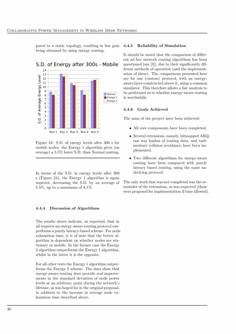
Collaborative Power Management in Wireless Mesh Networks
pared to a static topology, resulting in less gainbeing obtained by using energy routing.
Figure 24: S.D. of energy levels after 300 s formobile nodes: the Energy 1 algorithm gives (onaverage) a 5.5% lower S.D. than Normal routing.
In terms of the S.D. in energy levels after 300s (Figure 24), the Energy 1 algorithm is againsuperior, decreasing the S.D. by an average of5.5%, up to a maximum of 8.1%.
4.4.4 Discussion of Algorithms
The results above indicate, as expected, that inall respects an energy-aware routing protocol out-performs a purely latency-based scheme. For nodeexhaustion time, it is of note that the better al-gorithm is dependent on whether nodes are sta-tionary or mobile. In the former case the Energy2 algorithm outperforms the Energy 1 algorithm,whilst in the latter it is the opposite.
For all other tests the Energy 1 algorithm outper-forms the Energy 2 scheme. The data show thatenergy-aware routing does provide real improve-ments in the standard deviation of node powerlevels at an arbitrary point during the network’slifetime, as was hoped for in the original proposal,in addition to the increase in average node ex-haustion time described above.
4.4.5 Reliability of Simulation
It should be noted that the comparison of differ-ent ad hoc network routing algorithms has beenquestioned (see [3]), due to their significantly dif-ferent methods of operation (and the implement-ation of these). The comparisons presented hereare for one (custom) protocol, with an energy-aware layer constructed above it, using a commonsimulator. This therefore allows a fair analysis tobe performed as to whether energy-aware routingis worthwhile.
4.4.6 Goals Achieved
The aims of the project have been achieved:
• All core components have been completed.
• Several extensions, namely, bitmapped ARQ,one way hashes of routing data, and rudi-mentary collision avoidance, have been im-plemented.
• Two different algorithms for energy-awarerouting have been compared with purelylatency based routing, using the same un-derlying protocol.
The only work that was not completed was the re-mainder of the extensions, as was expected (thesewere proposed for implementation if time allowed).
30

David Cottingham
5 Conclusions
5.1 Outcome
The project has been a success: all acceptancecriteria given in the proposal have been achieved,and several extensions implemented.
As evidenced by the evaluation, using an energy-aware routing protocol can result in worthwhileimprovements in mesh network lifetime, up to6% in certain cases. Depending on whether themesh network is composed of mobile or station-ary nodes, a different energy-aware algorithm shouldbe used: the Energy 1 algorithm performs betterwith mobile nodes.
It is highly likely that the energy-aware metriccalculation algorithms presented could be refinedto have a much greater impact: with greater amountsof time and better automated results collection itwould be interesting to investigate this.
5.2 Further Work
Mobile ad hoc networks are still very much anactive research area, with security, energy man-agement, and scalability work ongoing. For theprotocol implemented in this project, the follow-ing are possible extensions:
• Investigating trust systems for openMANETs: various protocols have beensuggested using hash chains (e.g. TESLA [24])to prove the authenticity of a datagram’ssource in an open network. Adding supportfor such networks would mean the protocolwas suitable for ad hoc peer to peer (P2P)systems.
• Co-ordinate systems for mesh: tradi-tional peer to peer systems on wired net-works are subject to a high degree of churn,similar to the constantly changing topologyof a MANET. Research has been conduc-ted on co-ordinate systems for P2P [25],with a view to enabling nodes to access con-tent on the nearest host to them. Apply-ing such co-ordinate systems to mesh net-works could assist in decreasing the energyresources used, by relating the distances inthe co-ordinate space to the energy quotassystem.
• Hardware level power saving: the PENsystem [33] made use of layer 2 techniquesto reduce the power consumption of nodesby having defined hibernation periods. Thisdoes, however, increase the latency of thelinks in the network. Implementing suchpower saving features in the protocol fromthis project would certainly be worthwhile,although their use would depend on thelatency that could be tolerated.
• Zone routing and wired networks: modi-fying the routing protocol to have a hier-archical address space, to allow routing todifferent zones [36], is possible, but wouldtend to imply the existence of gateways toeach zone. In the same way some sort ofgateway paradigm is needed for interfacingwith wired networks. Reliability and en-ergy management at the gateway would makeworthwhile research.
31

Collaborative Power Management in Wireless Mesh Networks
32

David Cottingham
6 Appendix A: Survey of Ad
Hoc Routing Protocols
A more in depth analysis can be found in thesurvey by Royer and Toh [28], but specific detailsare given in the references for each protocol:
Table-Driven:
• DSDV: Destination-Sequenced Distance Vec-tor [22]. Each node maintains a table ofhop counts to all other destinations in thenetwork. Routing information is broadcastperiodically in dedicated packets. This treatsall nodes equally, but has a relatively highrouting data overhead.
• CGSR: Cluster-Head Gateway Switch Rout-ing [4]. Based on DSDV, but groups ofnodes (clusters) elect a control node that al-locates channel access and bandwidth. Rout-ing is via inter-cluster gateway nodes. Thisscheme has a very high overhead in cal-culating gateway/head nodes if the topo-logy is changing very frequently. It alsoplaces more of a processing workload on thecluster-heads and gateways, and has themas key single points of failure.
• WRP: Wireless Routing Protocol [18]. Sim-ilar again to DSDV, but to avoid the “countto infinity” problem, uses the second-to-lasthop for a destination as the attribute of aroute rather than a sequence number, toavoid loops. This provides faster route con-vergence on network partition.
Source-Driven:
• AODV: Ad-hoc On-demand Distance Vec-tor [23]. Nodes only store routes that arecurrently in use. When a node wishes tocommunicate with another, if it does nothave a valid route in its table it broadcastsa route request (RREQ) packet, which isthen propagated throughout the network.When the destination receives the RREQ,it unicasts a route reply (RREP) packetback towards the source. Intermediate nodesmaintain state as to which neighbour theyreceived the corresponding RREQ from first,and unicast the RREP back to that neigh-bour. The source therefore obtains a routethat is set up with the destination as the
root. This method has the problem of highroute-setup latency.
• DSR: Dynamic Source Routing [13]. Whena route is required, the source node broad-casts a request, containing its own address,and that of the destination. This is re-broadcast by all its neighbours, each addingtheir own address to the list of hops com-posing the route in the request packet. Whenthe packet reaches the destination, it willcontain the full route as a list of hops; thedestination simply unicasts this data backto the source. This implies that for a largenumber of hops routing packet sizes will besignificant. On network partition a largenumber of request messages are also likely,as new routes will need to be set up, ratherthan neighbours having multiple entries fora destination in their tables as in table-driven algorithms. Given that for each newdestination, regardless of similarity to a pre-viously learnt route, a node will cause network-wide broadcasts of requests, power usagewill be inefficient. In a network where thetopology rarely changes, the routing over-head for DSR can be as low as zero, oncethe network has stabilised. However, thesame could be said for source-routed wirednetwork protocols.
• TORA: Temporally Ordered Routing Al-gorithm [21]. A distributed link-reversal al-gorithm that relies on a synchronised clock(such as that provided by the Global Po-sitioning System), to order the protocol’sreaction to topology changes. During routecreation or maintenance phases, each nodeis assigned a height metric which determ-ines the direction of flow in a directed acyc-lic graph (DAG) rooted at the destinationof the route. The algorithm’s strength isthat in very large networks topology changesare communicated only to a small set ofnodes local to the change. However, thisrequires the mesh to be dense. An addi-tional problem is that the protocol has thepotential for “link flapping” as nodes eraseroutes and discover new ones based on eachother’s tables, but convergence will eventu-ally be achieved.
33

Collaborative Power Management in Wireless Mesh Networks
34

David Cottingham
7 Appendix B: Additional Im-
plementation Details
7.1 Detailed Packet Format
SourceDestinationLast HopNext HopLast Choice
Sequence Number IDSource Conn.Num
Routes Quota FlagsBitmap
Timestamp
Origin 1Source 1
Route 1
Route 6Origin 6
DeltaTime
Metric 1 Metric 2
Source 6
Dest. Conn. ID
Metric 3 Metric 4
Metric 5 Metric 6
32 Bits
Data
Routing MAC
Figure 25: The format of the packets used in theprotocol. each row represents 32 bits. There are6 sets of three routing data fields, only numbers1 and 6 are shown. The data field is of variablelength.
Source, Destination, Last Hop, Next Hop,Last Choice: contain the 32 bit addressesof the appropriate nodes.
Sequence Number: a 16 bit number identify-ing the position of the packet in the overallstream being transmitted.
Destination Connection ID: an 8 bit identi-fier, equivalent to a TCP destination portnumber.
Source Connection ID: the source “port” num-ber.
Number of Routes: the number of routingentries carried in the packet (ranging from0 to 6).
Quota: 8 bits specifying the transmission quotathe next hop node has on the last hop node.
Bitmap: 5 bits, set to indicate which packetsin the last chunk (series of five) have beenreceived, and which have not (used for bit-mapped ARQ).
Flags: 9 bits. Please see below for a completelisting.
Delta Time: 6 bits storing the time elapsedfrom the packet’s timestamp and it beingre-transmitted by the last hop node.
Timestamp: 32 bits, set by the original senderand unchanged bysubsequent hops.
Route x, Origin x, Source x: three 32 bitfields, holding the addresses needed for arouting entry. There are 6 sets of thesefields, although not all are required to befilled. See section 3.2.2 for details.
Metric x: six 16 bit fields, each specifying themetric from the last hop node to the tar-get destination in the corresponding Routefield (e.g. the route entry to destinationRoute 1 has a metric of Metric 1).
Routes MAC: a 96 bit Message Authentica-tion Code hash of the routing data in thepacket, calculated using a shared secret key,(see section 3.3.2).
Data: a variable length field, used to carry ap-plication level data.
Flags
The following 1 bit fields are located in the areamarked Flags in Figure 25:
Priority: set if the packet should be given pri-ority in the transmission or routing queues(provides a crude method of rating the im-portance of traffic).
35

Collaborative Power Management in Wireless Mesh Networks
Ack: set if the packet contains an acknowledge-ment, i.e. if the bitmap field should be readby the destination.
Multicast: set if the packet is for multicast (un-implemented – for future use).
Encrypted: set if the packet data is encryped(unimplemented – encryption is currentlyassumed to take place at application level,but could easily be implemented in the pro-tocol).
Routing Data: set if the packet contains anytype of routing data (route entries, or des-tination unreachable messages), or if thepacket is a plea.
Route Query: set if the packet is a plea for aroute to be supplied.
Destination Unreachable: set if the source fieldof the packet is not reachable from the lasthop node (see section 3.2.5).
Enough Resources: if unset in a destinationunreachable message, indicates that therewas an insufficient quota on one of the nodeson the route to forward the packet.
First Packet: set if this is the first packet to besent on this connection (see section 3.1.2).
7.2 Selfishness in Open Networks
Open networks, i.e. those with unrestricted mem-bership, differ from closed networks in that thereis no a priori trust available. Nodes may betrusted, or they may mount active or passive at-tacks on the mesh. The protocol designed in thisproject has not attempted to solve the securityproblems of open networks, but this section isincluded to justify this simplification.
Passive attacks are those in which a node doesnot act as a router in the network. This canresult in “black holes” in the network, causingnetwork partition. Such attacks can be serious ifthere are collaborating nodes that carry out thisattack.
Active attacks include spoofing, and reportingincorrect information, such as energy levels orquotas, to avoid the perpetrator being called uponto route data.
Attempting to ensure that routing is somehow“secure” in such an open network is complex, and
an active area of research. Credit based systems[8] appear to be a possible solution, providing in-centives for principles to be honest, but others in-volving decentralised public key management [2]have been proposed.
7.3 Event List & Time-outs
A significant part of any network protocol is itsusage of time-outs, and therefore its concept ofevents. In simulating the protocol under OPNET,the discrete event list management was handledby the simulation software itself. However, werethe protocol to be implemented outside the sim-ulator, event/timeout management could be per-formed using a delta list data structure as de-scribed by Comer and Stevens in [5]. Briefly sum-marised, this system maintains a linked list ofevents that are scheduled to take place, orderedby their relative due times. This is efficient asthe periodic timer need only decrement the timeof the event at the head of the list. When thetime in the first item reaches zero, the event isexecuted, and the next event moves to the headof the list.
36

David Cottingham
8 Appendix C: Values of Simulation Constants
The following details the values of the constants used in the simulation that have been mentionedthroughout the text. The below is taken directly from the C source file – any constants that relateto time are in units of milliseconds.
/* Estimate of average RTT to initially give a connection */#define RTT ESTIMATE 40
/* Number of RTTs the node waits for a packet from the destinationbefore a time out occurs. */#define TIMEOUT RTT MULTIPLE 2
/* Number of RTTs the node should wait for an ACK before starting resend.*/#define TIMEOUT RESEND RTT MULTIPLE 2 10
/* Maximum amount of simulation time that a connection can go withoutreceiving a packet before it is deemed unused and can be freed by thequeue allocator. */#define MAX IDLE TIME 80
/* Maximum amount of time before ACK gets sent: it may be that beforethis expires the ACK can be piggybacked on a data bearing packet, but inthe case it cannot, this time-out will expire and a non-data bearing ACKwill be sent. */ 20
#define TIME TO WAIT FOR CARRIER 10
/* The maximum number of repeat transmissions allowed for one chunkbefore the route the connection has been using is blackmarked. Value isone more than one entire chunk. */#define MAX RETRIES PER CHUNK 6
/* The maximum time period between forced “beacon” signals from nodes,if they have not sent any other packets in the meantime (the timeoutshould execute and test a flag to see if a packet has been sent. If so 30
then no action need be taken. If not, a beacon packet is transmitted. */#define T BEACON 50
/* The time for which a node should not allow a blackmarked route to beupdated by routes propagated for others. This is twice T BEACON, toallow network convergence. */#define T HOLD TIME 70
/* Above what fractional threshold of change in a route’s metric shoulda routing update be transmitted urgently. */ 40
#define THRESHOLD FRACTION METRIC UPDATE 0.5
/* The amount of time a route that has its metric set to 999 can be keptin a routing table entry list, before it is deleted. This time isdependent on how long it will take to update all the neighbours thatthis route is no longer valid. */#define T KEEP DEFUNCT ROUTES 45
37

Collaborative Power Management in Wireless Mesh Networks
/* Total number of pleas likely to be needing to be kept track of at onetime in the pleas hash table. */ 50
#define PLEAS TABLE SIZE 20
/* The maximum time for which a packet for a destination should becontinuously re-queued into the routing queue whilst we wait for ourneighbours to respond to our plea. */#define T ROUTE PLEA WAIT 80
/* The maximum amount of time for which, after a plea has expired (i.e.no route could be found), packets to the same destination will simply bedropped, without a new plea being sent. This is dependent on rate of 60
topology change. */#define T HOLD PLEA FAILURE 100
/* The fractional change in estimated node quota above which routemetrics are recalculated. */#define QUOTA METRIC UPDATE THRESHOLD FRACTION 0.1
/* The fraction by which a quota may change on quota reset below whichno quota update packet is sent. */#define QUOTA DELTA FRACTION FOR UPDATE 0.1 70
/* The interval between quota resets. Should be the same as T BEACON. */#define T QUOTA RESET INTERVAL 80
/* The initial estimate of this node’s quota on another node. Should beQUOTA ZERO THRESHOLD * 4 */#define START QUOTA ESTIMATE 20
38

David Cottingham
9 Appendix D: Simulator Finite State Machine
Figure 26: The finite state machine representing the protocol implemented in the OPNET simulator.Each state’s name is indicative of its function, with the conditions causing the transition above theirarcs.
39

Collaborative Power Management in Wireless Mesh Networks
40

David Cottingham
10 Appendix E: Sample Code
The below is the code used for quota management and metric calculation based on quotas on eachnode. Each function should be self explanatory.
void update quota estimate(Packet* packet to processx) {/* Updates our estimate of our quota on the last hop node of the packet. */
int srcQuotaAddress;int quotaq;struct neighbour* neighbourQuotaToUpdatey;char hashStringQuotay[4];
op pk nfd get(packet to processx, "last_hop", &srcQuotaAddress);op pk nfd get(packet to processx, "quota", "aq); 10
//itoa(srcQuotaAddress, hashStringQuotay, 3);sprintf(hashStringQuotay, "%d", srcQuotaAddress);
neighbourQuotaToUpdatey = prg string hash table item get(neighbours table,hashStringQuotay);
if (neighbourQuotaToUpdatey != PRGC NIL) {neighbourQuotaToUpdatey−>ourQuotaEstimate = quotaq;
}else { 20
printf("srcQuotaAddress = %d", srcQuotaAddress);op sim end("SIMULATION TERMINATED:", "Entry not found in neighbours
table", "in update_quota_estimate()", "(PROBABLY called from
route state).");}if (debug level >= 4) printf("\nAbout to call reCalcMetricsBasedOnQuota() in
update_quota_estimate().\n");reCalcMetricsBasedOnQuota(hashStringQuotay);
}30
void decrease quota estimate(Packet* packet to process) {/* Decreases our esimate of our quota on a neighbour node as we aresending a packet. */int destQuotaAddress;int nxHopQuotaAddress;struct neighbour* neighbourQuotaToUpdatex;char hashStringQuotax[4];
op pk nfd get(packet to process, "next_hop", &nxHopQuotaAddress);op pk nfd get(packet to process, "destination", &destQuotaAddress); 40
sprintf(hashStringQuotax, "%d", nxHopQuotaAddress);/* Only decrease the quota if this node is expected to transmit thepacket on - if not they will incurr no transmission energy usage. */if (nxHopQuotaAddress != destQuotaAddress) {
if ((neighbourQuotaToUpdatex = prg string hash table item get(neighbours table,hashStringQuotax)) != PRGC NIL) {
if (neighbourQuotaToUpdatex−>ourQuotaEstimate > 0) neighbourQuotaToUpdatex−>
ourQuotaEstimate = neighbourQuotaToUpdatex−>ourQuotaEstimate
41

Collaborative Power Management in Wireless Mesh Networks
− QUOTA PER PACKET COST; 50
reCalcMetricsBasedOnQuota(hashStringQuotax);}
}}
void update quota on this node(Packet* packet to process upd) {/* Decreases the quota of the last hop node of the packet on us (this node). */
int lastHopQuotaAddress;struct neighbour* neighbourQuotaToUpdate upd; 60
char hashStringQuota upd[4];
op pk nfd get(packet to process upd, "last_hop", &lastHopQuotaAddress);sprintf(hashStringQuota upd, "%d", lastHopQuotaAddress);
neighbourQuotaToUpdate upd = prg string hash table item get(neighbours table,hashStringQuota upd);
neighbourQuotaToUpdate upd−>theirQuota = neighbourQuotaToUpdate upd−>
theirQuota − QUOTA PER PACKET COST;} 70
int insert quota for next hop(Packet* pk to insert quota) {/* Inserts the next hop node’s quota on this node into the packet. */
int nxHopAddr;char hashString[4];struct neighbour* nxHopQuota;int quota to ins;
op pk nfd get(pk to insert quota, "next_hop", &nxHopAddr); 80
sprintf(hashString, "%d", nxHopAddr);
nxHopQuota = prg string hash table item get(neighbours table, hashString);quota to ins = nxHopQuota−>theirQuota;
return quota to ins;}
void reCalcMetricsBasedOnQuota(char* hashStringQuotaUpdatedz) {/* Decides whether the updated quota has undergone a significant 90
enough change to warrant updating all the route metrics associatedwith the node the quota is concerned with. */
struct neighbour* neighbourQuotaUpdatedz;int delta quota;int boolUpdateMetrics = 0;PrgT List* keysList;int i = 0, j = 0;char* keyRemoved;List* routeList; 100
int lengthList;struct route* route examining;int neighbourAddress;
42

David Cottingham
neighbourQuotaUpdatedz = prg string hash table item get(neighbours table,hashStringQuotaUpdatedz);
/* Ensures that the difference in quota is positive for thefractional test below. */delta quota = neighbourQuotaUpdatedz−>ourQuotaEstimate
− neighbourQuotaUpdatedz−>ourQuotaLastMetricUpdate; 110
if (delta quota < 0) delta quota = 1 − delta quota;
if ((neighbourQuotaUpdatedz−>ourQuotaLastMetricUpdate > 0) &&((delta quota/neighbourQuotaUpdatedz−>ourQuotaLastMetricUpdate) >
QUOTA METRIC UPDATE THRESHOLD FRACTION)) {/* Update all routes associated with this neighbour,as the quota has changed substantially since the lastmetrics update. */boolUpdateMetrics = 1;
} 120
if ((neighbourQuotaUpdatedz−>ourQuotaLastMetricUpdate == 0) &&(neighbourQuotaUpdatedz−>ourQuotaEstimate > QUOTA ZERO THRESHOLD)) {/* The quota for this neighbour was previously 0, but has now been updatedabove a threshold value, so update routes. If it were 0 and the update isbelow the threshold it is not worth updating the routes to make them validagain. */boolUpdateMetrics = 1;
}130
if (boolUpdateMetrics == 1 && use battery routing == 1) {
neighbourAddress = neighbourQuotaUpdatedz−>address;
/* Update all routes associated with this neighbour. */keysList = prg string hash table keys get(routing table);
while (i < op prg list size(keysList)) {if (debug level == −1) printf("\nrecalcMetricsBasedonQuota().");keyRemoved = (char*)op prg list remove(keysList,i); 140
routeList = (List*)prg string hash table item get(routing table, keyRemoved);lengthList = op prg list size(routeList);for (j=0; j<lengthList; j++) {
route examining = op prg list access(routeList, j);if (route examining−>nextHop == neighbourAddress) {
/* This route uses the neighbour that has had itsquota updated, so update the entry and resort the list. */route examining−>metric = metric calculator(route examining−>
metric, neighbourQuotaUpdatedz−>ourQuotaLastMetricUpdate,neighbourQuotaUpdatedz−>ourQuotaEstimate); 150
if (route examining−>metric == 0) {printf("\nneighbourQuotaUpdatedz->ourQuotaLastMetricUpdate = %d,
neighbourQuotaUpdatedz->ourQuotaEstimate = %d",neighbourQuotaUpdatedz−>ourQuotaLastMetricUpdate,neighbourQuotaUpdatedz−>ourQuotaEstimate);
op sim end("SIMULATION TERMINATED", "Metric is
0.", "See console", "x");
43

Collaborative Power Management in Wireless Mesh Networks
}route examining−>updateTime = (int)op sim time();route examining−>listInserter = 1818; 160
op prg list insert(urgent route list, route examining,OPC LISTPOS TAIL);
}}op prg list sort(routeList, compRouteMetrics);
}
/* Deallocate the elements on the list */op prg list free (keysList);/* Deallocate the list itself */ 170
op prg mem free (keysList);/* The quota used for the last metrics update for this neighbour must bechanged to the current quota. */neighbourQuotaUpdatedz−>ourQuotaLastMetricUpdate =
neighbourQuotaUpdatedz−>ourQuotaEstimate;}
}
int quota remaining(Packet* packet to test rem) {/* Tests to see whether the last hop of the packet has sufficient quota on this node to 180
have the packet relayed. Returns 1 if so, otherwise returns 0. */
int last hop v;char hashStringq[4];struct neighbour* neighbour to test rem;
/* If not using battery routing quota values do not matter. */if (use battery routing == 0) return 1;
neighbour to test rem = prg string hash table item get(neighbours table, hashStringq); 190
if (neighbour to test rem−>theirQuota < QUOTA PER PACKET COST) return 0;else return 1;
}
int metric calculator(int old metric, int old quota, int new quota) {/* Calculates a new route metric based on the old metric and the change in neighbourquota. Old Metric, m. New metric, n. Latency, l. Old quota, q. New quota, r.m = l * (1/q + 1)n = l * (1/r + 1)l = m/(1 + 1/q) 200
n = (m/(1 + 1/q))(1/r + 1)*/int new metric = old metric;int latency;double quotaFrac = old quota/INITIAL POWER LEVEL;
/* Without battery routing we only distribute latencies, therefore the old metric willbe a time, not a composite that must be re-calculated, as with battery routing enabled. */if ((use battery routing == 1) && (old quota != 0) && (old metric !=
INFINITE METRIC) && (battCalcMethod == 1)) latency = (int) 210
(old metric / (1.0 + (INITIAL POWER LEVEL / 2.0)/old quota));
44

David Cottingham
if ((use battery routing == 1) && (old quota != 0) && (old metric !=INFINITE METRIC) && (battCalcMethod == 2)) latency = (int)(old metric / (2.0 − quotaFrac));
if ((use battery routing == 1) && (old quota <= QUOTA ZERO THRESHOLD)&& (old metric == INFINITE METRIC)) {
/* Cannot calculate the latency from the old metric if this was set toINFINITE METRIC, so use initial estimate. This would be due to a quotabelow the threshold. */latency = RTT ESTIMATE; 220
}if ((use battery routing == 1) && (old quota > QUOTA ZERO THRESHOLD)
&& (old metric == INFINITE METRIC)) {/* Cannot calculate the latency from the old metric if this was set toINFINITE METRIC, so use initial estimate. This would be due to a latencythat was infinite. */latency = INFINITE METRIC; /* This is for clarity - it will have no effect. *//* This causes metric from latency and quota() to return a metricof INFINITE METRIC, as desired, as this route is still infinite latency. */new quota = 0; 230
}if ((use battery routing == 1) && (old quota == 0) && (old metric !=
INFINITE METRIC)) {/* Should not get here: any neighbour with zero quota should have a metric ofINFINITE METRIC already. */if (debug level > 0) op sim message("WARNING: In metric_calculator(),
old_quota == 0 with old_metric != INFINITE_METRIC", "Strange effects
may result! (setting latency = old_metric)");latency = old metric;
} 240
if (use battery routing == 0) { latency = old metric; }
new metric = metric from latency and quota(latency, new quota);
return new metric;}
int metric from latency and quota(int latency, int quota to use) {/* Calculates the metric to use from the latency and the quota to use. (Simple, butprovides one function to update). */ 250
int metric to return;if ((use battery routing == 1) && (quota to use != 0) && (battCalcMethod == 1))
metric to return = latency * (int)(1.0 + (INITIAL POWER LEVEL/2.0)/quota to use);if ((use battery routing == 1) && (quota to use != 0) && (battCalcMethod == 2))
metric to return = latency * (int)(2.0 − quota to use/INITIAL POWER LEVEL);if ((use battery routing == 1) && (quota to use == 0)) {
/* If the quota to use is 0 then the metric must be INFINITE METRIC. */metric to return = INFINITE METRIC;
} 260
if (use battery routing == 0) metric to return = latency;if (metric to return > INFINITE METRIC) {
metric to return = INFINITE METRIC;}
45

Collaborative Power Management in Wireless Mesh Networks
return metric to return;}
void quotas reset() { 270
/* Executed on a self interrupt (code 4). Resets the quotas for all neigbours of thisnode to a proportional share of the total power remaining on this node. */
int neighbours table size = 0;int quota to assign = 0;List* neighbours table list;struct neighbour* neighbour updating;int i = 0;int delta quota = 0;
280
neighbours table list = prg string hash table values get(neighbours table);neighbours table size = op prg list size(neighbours table list);
/* Prevent division by 0 when no neighbours are present, or have yet been found. */if (neighbours table size <= 0) neighbours table size = 1;quota to assign = (power level − RESIDUAL POWER LEVEL) /
neighbours table size;op stat write(quotaResetValue stathandle, quota to assign);neighbours table size = op prg list size(neighbours table list);
290
/* Assign this to all neighbours. */for (i=0; i < neighbours table size; i++) {
neighbour updating = op prg list access(neighbours table list, i);delta quota = neighbour updating−>theirQuota − quota to assign;if (delta quota < 0) delta quota = −delta quota;if (((neighbour updating−>theirQuota == 0) && (delta quota >
QUOTA ZERO THRESHOLD)) | | ((neighbour updating−>
theirQuota != 0) && ((delta quota/neighbour updating−>
theirQuota) > QUOTA DELTA FRACTION FOR UPDATE))) { 300
sendQuotaUpdate(neighbour updating−>address, quota to assign);}neighbour updating−>theirQuota = quota to assign;if (debug level >= 4) printf("Quota assigned to %d was %d",
neighbour updating−>address, neighbour updating−>theirQuota);}
/* Destroy the old quota reset timeout, if it exists, and create a new one. Theinterrupt code understood by process interrupts() is 4. */if ((op ev pending(quota reset timeout)) && (op ev time(quota reset timeout) <= 310
op sim time())) op ev cancel(quota reset timeout);quota reset timeout = op intrpt schedule self((op sim time() +
T QUOTA RESET INTERVAL), 4);}
void sendQuotaUpdate(int neighbourAddress, int new quota) {/* Transmits a routing update packet to a specific node to cause its estimate of itsquota on this node to be updated. These packets are sent due to greater thanQUOTA DELTA FRACTION FOR UPDATE fractional changes in quotas controlled
46

David Cottingham
by this node. */ 320
Packet* pk to send;
pk to send = op pk create fmt("AA-wbatt_pkt_format");op pk nfd set(pk to send, "source", thisNodeAddress);op pk nfd set(pk to send, "destination", neighbourAddress);op pk nfd set(pk to send, "last_hop", thisNodeAddress);op pk nfd set(pk to send, "last_choice", thisNodeAddress);op pk nfd set(pk to send, "seq_number", 0);op pk nfd set(pk to send, "ack", 0); 330
op pk nfd set(pk to send, "bitmap_ack", 0);op pk nfd set(pk to send, "dest_unreach", 0);op pk nfd set(pk to send, "route_query", 0);op pk nfd set(pk to send, "routing_data", 1);op pk nfd set(pk to send, "dest_unreach", 0);op pk nfd set(pk to send, "num_routes", 0);/* Note that this is for clarity only: in the routing algorithm the next hop is assignedthen the quota for that hop is inserted. Therefore this relies on the lowest metricand route to the neighbour being transmitting directly to it, which may not always be thecase. . . but for simplicity I assume that it is. The pathological case is when this 340
node has 0 quota on the neighbour node, causing the packet to take a different route.This is, however, unlikely. */op pk nfd set(pk to send, "quota", new quota);
op subq pk insert(ROUTING QUEUE, pk to send, OPC QPOS TAIL);}
47

Collaborative Power Management in Wireless Mesh Networks
48

David Cottingham
Bibliography
[1] F. Bennett, D. Clarke, J. Evans, A. Hopper,A. Jones, and D. Leask. Piconet – embeddedmobile networking. IEEE Personal Commu-nications, 4(5):8–15, October 1997.
[2] S. Capkun, L. Buttyan, and J. Hubaux. Self-organized public-key management for mo-bile ad hoc networks. In Proc. ACM Interna-tional Workshop on Wireless Security, WiSe2002., 2002.
[3] D. Cavin, Y. Sasson, and A. Schiper. Onthe accuracy of manet simulators. In Pro-ceedings of the second ACM internationalworkshop on Principles of mobile computing,pages 38–43. ACM Press, 2002.
[4] C. Chiang, H. Wu, W. Liu, and M. Gerla.Routing in clustered multihop, mobile wire-less networks. In Proc. IEEE SICON’97,pages 197–211, April 1997.
[5] D. Comer and D. Stevens. Internetworkingwith TCP/IP Volume 2. Addison-Wesley,1995.
[6] M. Conti, G. Turi, G. Maselli, J. Crow-croft, P. Michiardi S. Ostring, R. Molva,J. Costa Requena, I. Defilippis, S. Giordan,and A. Puiatti. Mobileman: Archi-tecture, protocols and services, deliver-able d5. IST 2001-38113, CNR, Cam-bridge University, Eurecom, HUT, SUPSI,September 2003. http://cnd.iit.cnr.it/mobileMAN/pub-deliv.html.
[7] S. Corson and J. Macker. Mobile ad hocnetworking (manet): Routing protocol per-formance issues and evauluation considera-tions. RFC 2501, IETF, January 1999.
[8] J. Crowcroft, R. Gibbens, F. Kelly, andS. Ostring. Modelling incentives for collab-oration in mobile ad hoc networks. In Proc.of WiOpt’03, 2003.
[9] G. Fairhurst and L. Wood. Advice to linkdesigners on link automatic repeat request(ARQ). RFC 3366, IETF, August 2002.
[10] Laura Marie Feeney. Ad hoc network-ing & IEEE 802.11. http://www.sics.se/
~lmfeeney/snus_802.11.pdf.
[11] Hedrick. Routing information protocol.RFC 1058, IETF, January 2001.
[12] Y. Hu, D. Johnson, and A. Perrig. Sead:Secure efficient distance vector routing inmobile wireless ad hoc networks. In FourthIEEE Workshop on Mobile Computing Sys-tems and Applications (WMCSA ’02), pages3–13, June 2002.
[13] D. Johnson, D. Maltz, and J. Broch.DSR The Dynamic Source Routing Protocolfor Multihop Wireless Ad Hoc Networks,chapter 5, pages 139–172. Addison-Wesley,2001.
[14] M. Kuhn and R. Anderson. Tamper resist-ance – a cautionary note. In Proceedings ofthe Second Usenix Workshop on ElectronicCommerce, pages 1–11, Nov 1996.
[15] K. Dantu M. Maleki and M. Pedram. Power-aware source routing protocol for mobile adhoc networks. In Proceedings of the 2002international symposium on Low power elec-tronics and design, pages 72–75. ACM Press,2002.
[16] L. Miller. Simulation model for theAODV MANET routing protocol.http://w3.antd.nist.gov/wctg/manet/
prd_aodvfiles.html.
[17] C. Moss. The nodes revolution. IEE Com-munications Engineer, 2(1):18–21, 2004.
[18] S. Murthy and J. J. Garcia-Luna-Aceves. Anefficient routing protocol for wireless net-works. Mobile Networks and Applications,1(2):183–197, 1996.
[19] W. Odom. Cisco CCNA, Exam #640-507Certification Guide. Cisco Press, 2001.
[20] P. Papadimitratos and Z.J. Haas. Securerouting for mobile ad hoc networks. In Proc.of SCS Communication Networks and Dis-tributed Systems Modeling and SimulationConference 2002, pages 27–31, 2002.
[21] V. D. Park and M. S. Corson. A highly ad-aptive distributed routing algorithm for mo-bile wireless networks. In INFOCOM (3),pages 1405–1413, 1997.
[22] C. Perkins and P. Bhagwat. Highly dynamicdestination-sequenced distance-vector rout-ing (DSDV) for mobile computers. In ACMSIGCOMM’94, pages 234–244, 1994.
49

Collaborative Power Management in Wireless Mesh Networks
[23] C.E. Perkins and E.M. Royer. Ad-hoc on-demand distance vector routing. In Proc.2nd IEEE Wksp. Mobile Comp. Sys. andApps., pages 90–100, February 1999.
[24] A. Perrig, R. Canetti, J. Tygar, and D. Song.The tesla broadcast authentication protocol.RSA CryptoBytes, 5(Summer), 2002.
[25] M. Pias, J. Crowcroft, S. Wilbur, T. Har-ris, and S. Bhatti. Lighthouses for scalabledistributed location. In 2nd InternationalWorkshop on Peer-to-Peer Systems (IPTPS’03), feb 2003.
[26] B. Preneel. Preimage resistance.http://www.win.tue.nl/~henkvt/
preimagev3.pdf.
[27] K. Rayner. Mesh wireless networking.IEE Communications Engineer, 1(5):44–47,2003.
[28] E. Royer and C. Toh. A review of currentrouting protocols for ad-hoc mobile wirelessnetworks. IEEE Personal Communications,pages 46–55, April 1999.
[29] E. Schenk and D. Bernstein. SYN cookies– mailing list archive. http://cr.yp.to/
syncookies/archive.
[30] S. Singh, M. Woo, and C.S. Raghavendra.Power aware routing in mobile ad hoc net-works. In Proc. 4th annual ACM/IEEE con-ference on Mobile computing and network-ing, pages 181–190. ACM Press, 1998.
[31] I. Sommerville. Software Engineering.Addison-Wesley, 1995.
[32] F. Stajano. Security for Ubiquitous Comput-ing. John Wiley and Sons, 2002.
[33] R. Stefanova, G. Girling, J.L.K. Wa, andP. Osborn. The design and implementa-tion of a low power ad hoc protocol stack.In Proc. IEEE Wireless Communicationsand Networking Conference, volume 3, pages1521–1529, September 2000.
[34] C.K. Toh. Maximum battery life routingto support ubiquitous mobile computing inwireless ad hoc networks. IEEE Communic-ations Magazine, 39(6):138–147, June 2001.
[35] G. Xylomenos, G. C. Polyzos, P. Mahonen,and M. Saaranen. TCP performance issuesover wireless links. IEEE CommunicationsMagazine, 39(4):52–58, 2001.
[36] M. Younis, M. Youssef, and K. Arisha.Energy-aware management for cluster-basedsensor networks. Computer Networks,43(5):649–668, 2003.
50

Proposer: David Cottingham
User ID: dnc25
College: Churchill
CST Part II Project Proposal
Collaborative Power Management in
Wireless Mesh Networks
October 2003
Project Originator: D. N. Cottingham
Resources Required: Please see the accompanying
Project Resource Form
Project Supervisor: Dr. J. K. Fawcett
Signature:
Director of Studies: Ms. C. H. Northeast
Signature:
Overseers: Prof. J. Crowcroft
Dr. K. Moody

Collaborative Power Management in Wireless Mesh Networks
Introduction
In the last two years the prevalence of wireless networking technologies has increased dramatically.Previously infrared was the mainstream technology used to connect portable devices, with lowbandwidths, and over a limited range: it is now commonplace to find an 802.11b “WiFi” transceiverin laptops and mobile telephones. Such explosive growth in wireless communication has found manyapplications where nodes are required to be mobile, or where fixed cabling is undesirable.
Many wireless devices use a paradigm best illustrated by the mobile telephone network: a mobilenode connects to a fixed (i.e. wired) base station, which then routes all data to and from that node.There are several consequences of this:
1. The transmission range of mobile nodes is limited, and therefore base station deployment isrequired to be relatively dense (or, consequently, coverage for mobile entities is not guaran-teed in many areas). This is both costly, and makes such devices useless in areas where theappropriate wired infrastructure is not in place.
2. Mobile node battery life is reduced due to transmission ranges being large (and thereforerequiring more power).
3. For any mobile node in a particular area, there is likely to be a single point of failure in itsconnection to other nodes: the wired base station.
4. As a consequence of the relatively high power of transmission, the likelihood that a signal willbe detected is increased – this is unfortunate in situations where a node’s location is to bekept secret.
Mesh networks aim to lessen the above by dynamically routing data between nodes, i.e. packetsare sent via other nodes to eventually reach their destination, (be this a wired node or anotherwireless entity). The RFC for mobile ad hoc networks5 provides an excellent description of theneeds and issues surrounding their implementation, and mentions specifically energy resources as amajor concern.
Several applications of wireless mesh networks are:
• Sensor networks – large manufacturing plants have hundreds of sensors that require a connec-tion back to a central control room. Instead of wiring them in, they are implemented as amesh network, providing far greater flexibility and lowered cost.
• Traffic networks – data can be routed between cars in a city to and from wired base stations.
• Wireless MANs – broadband access is made possible in remote areas by routing packets viaother subscriber nodes. Whilst these are not mobile nodes, the system must deal with nodesbeing unavailable, and interference.
This project aims to design and implement (possibly entirely within a simulator) aprotocol for mobile ad hoc networks that will conserve node resources by making rout-ing choices that are dependent on the remaining energy of the nodes making up thealternative routes. This will provide resilience and high availability for communicationbetween all nodes in the network.
5RFC 2501 – Corson, Macker, Batsell. IETF, January 2001
52

David Cottingham
Work to be Undertaken
The implementation of collaborative power management in an ad hoc wireless network necessitatesseveral core components, which will be required for the project to be deemed as a success. Othercomponents that improve the security of the system or that enable it to run more efficiently will beextensions. These are outlined below.
Core Components
Each component listed has the OSI layer to which it corresponds approximately at the end of itsdescription. Note that physical connectivity, framing, CRCs (Layer 1), will be provided by theC/C++ libraries being used. There is therefore no specific module to be written for this. Thisproject will not attempt to investigate hardware solutions for increasing battery life.
1. Transport Module: defines packet format, sending and receiving methods, ARQ (AutomatedRepeat Request) system (Layer 2). This will allow two nodes to connect and send/receive dataon a direct connection with some packet loss.
2. Routing Module: discovers, maintains, and propagates routes. Chooses optimum route forsending (Layer 3). This will allow multiple nodes to relay packets between each other on theoptimum routes with diverse paths in existence.
3. Energy-Aware Routing Module: varies link “goodness” (equivalent to latency) with energyreserves remaining. Interacts with Routing Module to predict remaining energy on remotenodes, and provides a credit-based energy system, whereby each relayed transmission decreasesthe sender’s credit on the relaying node (Layer 3).
4. Application Module: This will take input from the console, output results, and interface withsimulation software (Layer ∼5).
Extensions
The following are possible extensions to the project, should time allow.
• Trusted Routing Information: routing using the core modules will result in the security risk thatbogus routes might be introduced, or genuine ones deleted by malicious nodes. To overcomethis problem, a shared secret would be used by all trusted nodes in the network to obtain aone way hash of any routing information they transmit. On reception, if another node cannotobtain the same hash value, the routes received are ignored. Note that this does not preventagainst internal attacks.
• Bitmapped ARQ: to conserve energy, a transmission control protocol is envisaged that wouldonly send an ACK every, say, 5 packets of data received. A bitmapped ARQ system allowsthe receiver to tell the sender which of 5 packets have been received successfully.
• Encryption: wireless networks are a great deal more open to eavesdropping than wired links.Therefore it is necessary that data be encrypted between the source and destination, but usingas little CPU time (i.e. energy) as possible.
• Multicast Traffic: the project is designed only for unicast traffic. It is likely that in someapplications there would be several nodes that data should be sent to. To avoid sendingout identical data multiple times, multicast groups could be established, and the data onlytransmitted once. The beauty of this is that no extra transmissions are needed: becausetransmissions are broadcast, all nearest neighbours (i.e. next hops) receive them, and thereforeall potential subscribers to the group can be (indirectly) reached.
53

Collaborative Power Management in Wireless Mesh Networks
• Link Contention/Collision Detection: for the purposes of the core project it will be assumedthat collisions will be detected indirectly by the ARQ protocol, and on retransmission colli-sions will not continuously occur. In a real application it would be necessary to implementrandomised retransmission timers to prevent a second collision on retransmission.
Resources Required
Please see the associated project resource form for full details of the resource requirements for thisproject.
Starting Point
There has a substantial amount of work carried out on wireless mesh networks in many differentcontexts. Perhaps the most relevant work has been carried out at the Cambridge University Labor-atory for Communications Engineering (LCE), and AT&T Labs: their Piconet (later PEN) project6,concentrated on building a low power mesh network using a combination of hardware and low levelnetwork protocol features. Later work on a proactive routing protocol for PEN was also carriedout7, and some of the ideas from this work are to be re-implemented here. Other mesh technologiesand routing algorithms such as the Temporally-Ordered Routing Algorithm8, Destination-SequencedDistance Vector protocol9, and wired protocols such as the Routing Information Protocol10 have alsobeen considered and various ideas will be used from them.
To the best of my knowledge there has been no published work on routing algorithms that attemptto take into account the resources (and in this case, specifically energy levels remaining) of nodes inthe network.
Security in wireless mesh networks is also a well researched topic. Stajano’s text on the implicationsof ubiquitous computing11 points out various security issues, some of which could be solved by theproject and its extensions (in particular the problem of DoS attacks resulting in “sleep deprivation”and thereby battery exhaustion). Another useful overview by Wang, Lu, and Bhargava12 will be thebasis for several design decisions for the protocol.
My experience with C/C++ programming is minimal, and therefore initially time will need to bespent sharpening my network programming skills in this area. In addition, I do not have anyexperience with network simulation software (in this case I hope to use OPNET), which will againwarrant a somewhat steep learning curve. I have a fairly wide experience of networking technologies.
Measures of Success
The project will be deemed to have been a success when all items described above as core componentshave been implemented and tested successfully, along with any extensions that time allows.
6Piconet - Embedded Mobile Networking – Bennett, Clarke, Evans, Hopper, Jones, Leask. IEEE Personal Com-munications, Vol. 4, No. 5, October 1997, pp 8-15.
7The Design and Implementation of a Low Power Ad Hoc Protocol Stack – Li Kam Wa, Osborn, Stefanova.Presented at IEEE Wireless Communications and Networking Conference, September 2000.
8A Highly Adaptive Distributed Routing Algorithm for Mobile Wireless Networks – Park, Corson. Published inthe proceedings of INFOCOM’97.
9Highly Dynamic Destination-Sequenced Distance Vector Routing (DSDV) for Mobile Computers – Perkins, Bhag-watt. ACM SIGCOMM October 1994.
10RFC 1058 – Hedrick. IETF, January 200111Security for Ubiquitous Computing – Stajano. Wiley 2002.12On Security Study of Two Distance Vector Routing Protocols for Mobile Ad Hoc Networks – Wang, Lu, Bhargava.
CERIAS, 2003.
54

David Cottingham
Network simulations will be performed to compare the spread of energy levels in an ad hoc networkafter a specified running time with “standard” routing, and with energy aware routing. Othermeasurements may be performed as time allows.
Project Plan
The work for this project will be broken down into 2 week work “packets”, each of which will havean identifiable deliverable associated with it.
Noteworthy dates:
• Progress Report due Friday 30th of January.
• Final Dissertation due Friday 14th of May.
55

Collaborative Power Management in Wireless Mesh Networks
# Start End Description Deliverable(s)1 18/10/2003 31/10/2003 Investigation (80%) & Design Packet format specification,
(20%) draft transport protocolInvestigation: specification.Research C/C++ network programming,understand possibilities of networksimulation software and how best tocode to make use of it.Design:Specify protocol packet format, beginspecification of transport protocol.
2 01/11/2003 14/11/2003 Design (80%) & Test Plan Specifications for Routing(20%) and Energy Routing complete.Design: High level test plan.Complete specification of routing prot.specify energy aware routing prot. &Application module.Test Plan:Devise high level module test plan.
3 15/11/2003 28/11/2003 Implementation I Hosts to be able to carry outImplement enough of the system to bi-directional communicationenable direct communication between using the basic Transporttwo hosts running the Transport and protocol, with ARQ.Application modules. ARQ.
4 29/11/2003 12/12/2003 Implementation II Multiple hosts able to be onImplement Routing module, initially network. Dynamic routingwith static routes (i.e. no updates), with updates to work.then with dynamic distance vector Energy Routing module begun.routing. Begin Energy Routing module.
5 13/12/2003 23/12/2003 Implementation III All routing should now work.Finish Energy Aware Routing. Hosts should be able toInterface with simulation software. communicate despite networkFix problems. partitions and packet loss.(Work over Christmas)
6 10/01/2004 23/01/2004 Progress Report, Testing Progress report deadline:Write progress report. 30/01/2004.Construct simulation models and carry Initial simulations complete.out simulations to obtain data.
7 24/01/2004 06/02/2004 Testing None.Continue simulations.
8 07/02/2004 20/02/2004 Testing/Dissertation Writing I Simulation conclusions.Complete simulations, interpret data.Begin dissertation.
9 21/02/2004 05/03/2004 Dissertation Writing II None.Continue dissertation.
10 06/03/2004 19/03/2004 Dissertation Writing III First draft complete.Complete first draft.
11 20/03/2004 02/04/2004 Dissertation Writing IV Dissertation complete.Correct draft, finalise report.
12 03/04/2004 16/04/2004 Contingency I N/A.Just in case...
13 17/04/2004 30/04/2004 Contingency II N/A.
56

David Cottingham
Contingency Plan
If, once simulation software has been investigated, it is decided that none of the third party packagesis a viable option, a simple custom simulator will be developed, with test cases developed by handinvolving a limited number of nodes in the network. This should be sufficient to show that the mainbody of code functions correctly.
57