Embed Size (px)
Citation preview

arX
iv:1
311.
7000
v1 [
phys
ics.
flu-
dyn]
27
Nov
201
3
Encapsulated formulation of the Selective Frequency Damping
method
Bastien E. Jordi, Colin J. Cotter, Spencer J. Sherwin
December 13, 2017
Abstract
We present an alternative “encapsulated” formulation of the Selective Frequency Dampingmethod for finding unstable equilibria of dynamical systems, which is particularly useful whenanalysing the stability of fluid flows. The formulation makes use of splitting methods, whichmeans that it can be wrapped around an existing time-stepping code as a “black box”. Themethod is first applied to a scalar problem in order to analyse its stability and highlight theroles of the control coefficient χ and the filter width ∆ in the convergence (or not) towards thesteady-state. Then the steady-state of the incompressible flow past a two-dimensional cylinder atRe = 100, obtained with a code which implements the spectral/hp element method, is presented.
1 Introduction
A deep understanding of the underlying physics of boundary layer separation behaviour is crucial
when considering the problem of controlling detached flows. Flow instabilities may be the cause of
this separation. A stability analysis of a flow can help to predict when these instabilities arise, and
can be used to design flow controllers. To perform a stability analysis, it is necessary to construct
the “base flow” around which the system will be linearised. This leads to the challenge of obtaining
a steady state solution of the Navier-Stokes equations. There are alternatives to this, namely to
compute the time average of an unsteady solution, or to obtain a solution of the Reynolds averaged
Navier-Stokes (RANS) equations to use as the base flow. However, these solutions often produce
stability properties which are not relevant to the physical solution [1]. Hence, we are interested
in solver algorithms to obtain genuine steady-state solutions of the Navier-Stokes equations. One
possible approach is to use Newton’s method, however it must be combined with a continuation
method since a good initial guess of the solution is required to ensure convergence. For challenging
flow problems at high Reynolds number, it may be the case that many complicated bifurcations at
various Reynolds numbers must be crossed before finding the required solution. As an alternative,
Akervik et al. [2] presented a modification of the time-dependent dynamical system, called Selective
Frequency Damping (SFD), which tries to reach the steady-state of an unsteady system by damping
unstable temporal frequencies. Since it is easy to implement into an existing code, and does not
1

need a good initial guess, this method appeared to be an efficient alternative to classical Newton’s
methods. The SFD method has been successfully applied to find steady-solutions of the Navier-
Stokes equations, which were then used as a base flow to study stability properties of flows such as
the wake of a sphere [3], a jet in a crossflow [4] or a cavity flow [5]. However Jones and Sandberg [6]
failed to find the steady-state of the compressible flow around a NACA-0012 airfoil at Re = 1× 10⁶
using the SFD method. It was assumed there that the method was not able to suppress the
instabilities present at this Reynolds number without requiring a large damping coefficient and
hence impractically long time-integration to converge. Vyazmina [7] studied swirling flows and it
was noticed that the SFD method did not converge towards the steady-state when the problem
considered had real unstable eigenvalues.
In this paper we present a time discrete formulation of the SFD method which is implemented
as a wrapper around an existing ”black box” unsteady solver. In section 2 we first recall the original
form of the SFD method and then show that with the splitting methods framework the method
can be reformulated. This alternative formulation encapsulates the existing solver. This scheme
is applied to a simple one-dimensional problem in section 3. The convergence properties of this
formulation are studied in order to provide information about the influence of the filter width and
the control coefficient on the stability of the method. Then the results obtained by the application
of the encapsulated SFD method to a high-order incompressible Navier-Stokes solver are presented
in section 4. Finally, we introduce the idea that isolating the most unstable eigenmode of a flow
problem and treating it as a one-dimensional problem can give sufficient information in order to
ensure the convergence of the SFD problem applied to a Navier-Stokes solver.
2 Problem formulation
We first recall the basis of the SFD method as it was originally introduced. Then we present
the discretized encapsulated formulation.
With appropriate initial and boundary conditions, any system can be written
q = f(q), (1)
where q represents the problem unknown(s), the dot represents the time derivative and f is an
operator (which can be nonlinear). The steady-state qs of this problem is reached when qs =
f(qs) = 0.
The main idea of the SFD method is to introduce a linear forcing term on the right-hand side
of (1). This term must contain a control coefficient and a target towards which the solution will be
driven to. A new problem formulation is then defined such as
q = f(q)− χ(q − qs), (2)
where χ is the control coefficient and qs is the target steady-state. This stabilization technique
is called proportional feedback control and is commonly used in control theory [8]. When qs is a
2

genuine steady-state, i.e., f(qs) = 0, the steady solution of (2) is clearly also the steady solution of
(1). However, in practice, especially for real flow problems, the steady-state is generally not known
a priori. The SFD method addresses this by replacing qs by a low-pass filtered version of q, denoted
q. By damping the most dangerous frequencies, the corresponding instabilities are extinguished [2].
This idea was originally introduced by Pruett et al. [9, 10] in their work on a temporal filtered
model developed for large-eddy simulations.
The differential form of a (first order) low-pass time filter can be defined as
˙q =q − q
∆, (3)
where q is the temporally filtered quantity and ∆ is the filter width. This equation can be advanced
in time using any appropriate integration scheme.
Considering (2), with the new target solution q, and the filter (3), we obtain the system
{
q = f(q)− χ(q − q),
˙q = q−q∆ .
(4)
This system is the continuous time formulation of the SFD method, as it was first introduced
[2]. The filtered solution q is time varying, and the steady-state is reached when q = q. We now
present a time-discrete implementation of the SFD method which allows us to wrap code around
an existing time-stepping scheme for equation 1. This notion can be linked to Tuckerman’s work
[11] on the adaptation of time-stepping codes to carry out efficient bifurcation analysis.
System (4) can be discretised within the framework of sequential operator-splitting methods
[12]. The system is divided into two smaller subsystems which are solved separately using different
numerical schemes. The first subproblem (which can be nonlinear) is simply (1). We introduce the
function Φ such that the numerical (or exact) solution of (1) at the step (n+ 1) is given by
qn+1 = Φ(qn). (5)
The second subproblem is linear and represents the actions of the feedback control and the
low-pass time filter. It can be formulated
{
q = −χ(q − q)
˙q = q−q∆
⇐⇒
(
q˙q
)
=
(
−χI χI
I/∆ −I/∆
)(
q
q
)
, (6)
where I is the identity matrix. The linear operator defined by (6) will be denoted L. This equation
can be solved exactly on [tn, tn +∆t] and the solution is given by
(
q(tn+1)
q(tn+1)
)
= eL∆t
(
q(tn)
q(tn)
)
, (7)
3

where the expanded expression of eL∆t is
eL∆t =1
1 + χ∆×
(
I + χ∆Ie−(χ+ 1
∆)∆t χ∆I[1− e−(χ+ 1
∆)∆t]
I − Ie−(χ+ 1
∆)∆t χ∆I + Ie−(χ+ 1
∆)∆t
)
. (8)
In the construction of a splitting method, the final solution of one subproblem is used as initial
condition of the other one. As (5) does not affect q, the discrete formulation of (4) using a first
order splitting method is given by
(
qn+1
qn+1
)
= eL∆t
(
Φ(qn)
qn
)
, (9)
where ∆t is the time step used within the solver Φ. We call this scheme “encapsulated” since Φ
is not modified but simply used as an input of the linear solver (7). Hence Φ can be treated as a
“black box”. Codes which solve the Navier-Stokes equations are usually very complicated. If the
original problem (1) is a flow problem, implementing an efficient steady-state solver with minimum
programming effort can be highly valuable. To implement (9) in an existing code, the only work
required is to create an auxiliary variable q∗ which takes the value of the outcome of (5). Then
the linear operator eL∆t (which is constant through time) simply has to be applied to the vector
(q∗, qn)T . Note that a second order Strang splitting method can also be used to solve (4). For
clarity we only present the first order scheme here.
This method does not converge to a steady-state for arbitrary control coefficient χ and filter
width ∆. If Φ is a linear map, the convergence of (9) towards the steady-state of (1) is guaranteed
if all the eigenvalue magnitudes of this system are strictly smaller than one. Such a system is said
to be (linearly) stable. As (9) depends on χ and ∆, these parameters play a key role in the stability
of the SFD method. In the next section, we analyse this role, using a one-dimensional model.
3 Scalar problem
In this section a simple one-dimensional problem is studied in order to analyse the influence of χ
and ∆ on the stability of the SFD method. A clear understanding of their role should help users of
the SFD method to choose parameters that ensure its convergence. The scalar problem considered
is
u = γu, (10)
where γ ∈ C. This equation has exact solver
un+1 = Φ1D(un) = αun, α = eγ∆t. (11)
For the remainder of this section we set ∆t = 1.
The convergence towards the steady-state of (11) (i. e. un+1 = un) is guaranteed if |α| < 1.
We aim to use SFD to reach the steady-state of (11) when |α| > 1. Analysing this simple case will
4

allow us to highlight the roles of the parameters χ and ∆ in the convergence (or not) of the SFD
method.
In order to write the encapsulated formulation of the SFD method applied to (11), we use the
function Φ1D such that Φ1D(un) = αun. Then we introduce the operator L1D ∈ M2(R) which has
the same form as (6) upon replacing I with 1. The application of the encapsulated formulation of
the SFD method to (11) becomes
(
un+1
un+1
)
= eL1D
(
αun
un
)
= eL1D
(
α 0
0 1
)(
un
un
)
. (12)
The eigenvalues (noted λ1 and λ2) of the matrix defined by system (12) can then easily be
evaluated, as functions of the control coefficient χ, the filter width ∆ and the complex number α.
To ensure the stability of (12), we want to be able to choose χ and ∆ such that max(|λ1|, |λ2|) < 1.
From these eigenvalues we obtain the following limiting behaviour for small χ and ∆:
limχ→0
λ1 = α,
limχ→0
λ2 = e−1/∆,
lim∆→0
λ1 = α,
lim∆→0
λ2 = 0.(13)
If the original problem is not converging, applying the SFD method and choosing a small control
coefficient χ will not drive the solution towards its steady-state. We also obtain the following large
χ and ∆ limits:
limχ→+∞
λ1 = 1,
limχ→+∞
λ2 = 0,
lim∆→+∞
λ1 = αe−χ,
lim∆→+∞
λ2 = 1.(14)
If the control coefficient χ (or the filter width ∆) is chosen to be large, the encapsulated for-
mulation of the SFD method is marginally stable. The steady-state can not be reached but the
solution does not blow up.
We now examine the stability regions of the encapsulated formulations of the SFD method. The
goal, for a given control coefficient and filter width, is to identify for which α the one-dimensional
problem will converge towards its steady-state. This section is only focused on the influence of χ
and ∆.
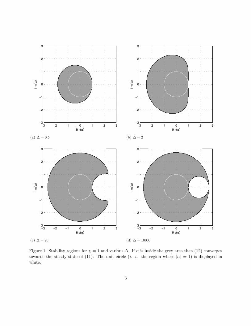
In the stability diagram in Figure 1, each point of the complex plane corresponds to the value of
α. The values of χ and ∆ are fixed for every point, and the eigenvalues of matrix (12) are evaluated.
If both eigenvalue magnitudes are smaller than one, then the point is coloured in grey. Hence the
grey area corresponds to the stability region of (12). In other words, Figure 1(a) tells us that χ = 1
and ∆ = 0.5 will drive (12) towards its steady-state for every α chosen within the grey area.
We recall that (11) was stable only if |α| < 1 (i. e. only if α was situated within the unit disc,
delimited by the white circle on Figure 1). The stability region of (12) expands beyond the unit
disc. These pictures allow us to visualize the fact that the SFD method stabilizes unstable modes.
5
Re(α)
Im(α)
−3 −2 −1 0 1 2 3
−3
−2
−1
0
1
2
3
(a) ∆ = 0.5
Re(α)Im
(α)
−3 −2 −1 0 1 2 3
−3
−2
−1
0
1
2
3
(b) ∆ = 2
Re(α)
Im(α)
−3 −2 −1 0 1 2 3
−3
−2
−1
0
1
2
3
(c) ∆ = 20
Re(α)
Im(α)
−3 −2 −1 0 1 2 3
−3
−2
−1
0
1
2
3
(d) ∆ = 10000
Figure 1: Stability regions for χ = 1 and various ∆. If α is inside the grey area then (12) converges
towards the steady-state of (11). The unit circle (i. e. the region where |α| = 1) is displayed in
white.
6

Re(α)
Im(α)
−3 −2 −1 0 1 2 3
−3
−2
−1
0
1
2
3
Figure 2: Contours of the stability regions of (12) for ∆ = 20 and two different χ. The central circle
represents the boundary of the unit disc.
This is achieved without introducing a loss of stability elsewhere, indeed the stability region of the
original problem (i. e. the unit disc) is inside the stability region.
On each stability diagram presented in Figure 1, we notice that if α is real and greater than
one, it is not possible to find a couple χ and ∆ for which (12) is stable. Such an α corresponds to a
problem with a pure exponential growth of the instability. Hence we can conclude that the stability
of the SFD method relies on the oscillatory growth of the problem studied. This is because time
averaging oscillatory growth produces a good estimate of the equilibrium, whilst time averaging
exponential growth does not. This was reported by Vyazmina [7], who said that if an unstable
eigenvalue is real and positive, there is no frequency to be damped by the SFD method.
Figure 1 presents stability regions for a fixed value of the control coefficient χ. With a different
χ, the shape of these stability regions would have been similar but the area covered would have
been different. This behaviour is shown in Figure 2.
Akervik et al. [2] stated that choosing a large χ or a large ∆ would make the system evolution
very slow but the SFD method would eventually converge to a steady-state. The results presented
in Figure 2 suggest that this may not always be true. Indeed, this picture shows that there is a
region where (12) is stable for χ = 0.5 and ∆ = 20 but unstable for χ = 1 and ∆ = 20. Hence
increasing the control coefficient is not always an appropriate method to guarantee the convergence
of the SFD method towards the steady-state.
7

When choosing a large filter width, the behaviour of the SFD method is slightly different. For
a given χ and a large ∆, if the SFD method is not stable then it is not possible to find a smaller ∆
for which the method is stable. This is illustrated by the fact that the regions presented in Figures
1(a), 1(b) and 1(c) are all included within the region presented in Figure 1(d). However, choosing a
very large ∆ does not guarantee the stability of (12). If α is situated at the right of the unit circle,
close to the real axis, increasing the filter with without acting on the control coefficient might not
be enough to enable the SFD method to converge.
When χ = 0 and when ∆ tends to zero, the stability region of (12) fits exactly within the
unit circle, confirming the outcome of the limiting behaviour analysis for the scalar problem (for
conciseness these figures are not presented here).
If a second order Strang splitting method is used to reformulate (4) applied to the scalar problem
(11), the stability regions obtained are exactly the same as the ones presented in this section. This
is because the second-order splitting can be written as a shifted first-order splitting with a pre- and
post-processing step, so both methods have the same stability regions.
4 Numerical simulations: the cylinder flow at Re = 100
The encapsulated SFD method (9) was implemented into the Nektar++ spectral/hp element
framework [13], as a wrapper function. In order to find the steady state solution of the incompressible
Navier-Stokes equations, a solver which implements the velocity-correction scheme [14] (symbolised
by the functions Φ in (9)) is called at each time-step. In this section we present the numerical
steady-state of the two dimensional cylinder flow above its critical Reynolds number Rec (i. e.
when the Reynolds number is high enough such that the viscous forces within the flow are not
dominant).
At Re = 100 the two-dimensional incompressible flow past a cylinder is unstable and von
Karman vortex streets are observable. Indeed, shedding vortices appear when Re > Rec ≃ 47 and
this phenomenon remains until the end of the subcritical regime (Re ≃ 2×10⁵) [15]. Hence the role
of the SFD method is to suppress these oscillations and drive the solution towards its steady-state.
The computational domain dimensions are −15 ≤ x ≤ 45 and −25 ≤ y ≤ 25. The cylinder is
centred at the origin and its diameter is one unit length. Close to the cylinder the mesh composed of
structured quadrilateral elements; elsewhere, the mesh is composed of triangular elements. On the
cylinder surface, no-slip boundary conditions are imposed. Dirichlet boundary conditions (u, v) =
(1, 0) are imposed on the left, top and bottom edges. Finally an outflow boundary condition is set
on the right edge. As the steady solution is expected to be smooth, a high polynomial order of 11 is
used. To highlight the fact that, in contrast to Newton’s methods, the SFD method does not need
a good approximation of the final solution to converge, initial conditions such as (u0, v0) = (0, 0)
are chosen. The SFD parameters are initially chosen such that the control coefficient χ = 1 and the
filter width ∆ = 2. The problem is considered to have converged when ||qn − qn||inf < 10−8. The
8

(a) Snapshot of the uncontrolled flow (unsteady and peri-
odic). This behaviour is the well known von Karman
shedding.
(b) Unstable steady-state obtained by SFD. The dashed
lines represent the separating streamlines.
Figure 3: Vorticity (ω = ∂xv − ∂yu) of the incompressible flow past a two-dimensional cylinder at
Re = 100. Note that only a small part of the whole computational domain is displayed.
steady-state has been obtained after the computation of about 1000 time units (with the time-step
∆t = 0.01) and the decay of ||qn − qn||inf is exponential.
Figure 3(a) is simply a reminder of the behaviour of the uncontrolled incompressible cylinder flow
at Re = 100 and the steady-state obtained by SFD is shown on Figure 3(b). This flow configuration
is identical to the one presented by Barkley [1].
A stability analysis, using an Arnoldi method, is performed with this steady-state as the ”base
flow”. The growth rate σ and the frequency f of this flow configuration are
σ = 0.12978 and f = 2π × 0.11769, (15)
which correspond to the values presented by Barkley [1]. If the time length of each Arnoldi iteration
is defined as being equal to one time unit, this growth rate and this frequency correspond to the
two dominant (conjugate) eigenvalues
λ1,2 = 1.13857e±0.73944i. (16)
As |λ1,2| > 1, the flow is unstable and the corresponding instabilities exponentially grow through
time. However the SFD method was able to stabilise the flow and allowed it to converge towards
its steady-state.
We now verify that if the SFD method is able to stabilize the most unstable eigenmode of a
flow problem then the method will converge towards the steady flow. In other words, if λD is the
dominant unstable (i. e. |λD| > 1) eigenvalue of a flow problem. If the parameters χD and ∆D
enable to reach the steady-state of the scalar problem un+1 = λDun. Then we want to know if the
same parameters will also enable the SFD method to reach the steady-state of the flow problem.
Figure 4 shows the contours of several stability regions of (12), superposed with the position of
the dominant (conjugate) eigenvalues (16) of the cylinder flow at Re = 100. (Note that the stability
9

Re(α)
Im(α)
−3 −2 −1 0 1 2 3
−3
−2
−1
0
1
2
3
Figure 4: Contours of the stability regions of (12) for χ = 1 and various ∆. The central circle
represents the boundary of the unit disc. The two black crosses indicate the position of the dominant
unstable eigenvalues (16) of the cylinder flow at Re = 100.
10

1e-08
1e-06
0.0001
0.01
1
0 1500 3000 4500
||q−
q|| inf
Time
χ = 1 and ∆ = 2χ = 1 and ∆ = 1
(a)
0.1
0 100 200 300
||q−
q|| inf
Time
χ = 1 and ∆ = 0.5
(b)
Figure 5: Time evolution of ||q− q||inf for parameters which allow the encapsulated SFD method to
converge towards the steady-state (a); and for parameters which do not (b). The cases presented
here have been computed with the time-step ∆t = 0.01.
regions of χ = 1, ∆ = 0.5 and χ = 1, ∆ = 2 are the ones shown on Figure 1(a) and 1(b)). We notice
that for χ = 1 and ∆ = 1 and also for χ = 1 and ∆ = 2, the unstable eigenvalues (16) are situated
inside the stability region of (12). These parameter couples have been used to apply the SFD
method to the Navier-Stokes solver and with both, the steady solution was obtained. However the
computational time required to reach convergence strongly depends χ and ∆. Figure 5(a) compares
the number of iterations computed by the Navier-Stokes solver before obtaining the steady-state.
With χ = 1 and ∆ = 1 the SFD method needs about 4 times as many iterations to converge than
with χ = 1 and ∆ = 2. Increasing the filter width does not always decrease the computation time
of the method. Indeed when ∆ becomes too large, we obtain the expected limiting behaviour.
For χ = 1 and ∆ = 0.5, the unstable eigenvalues (16) are situated outside the stability region of
(12). When this parameter couple is used to apply the SFD method to the cylinder flow, the steady-
state can not be obtained. Figure 6 presents the outcome of the method with these parameters.
This flow is not steady but the oscillations are attenuated in comparison with the flow presented in
Figure 3(a). Figure 5(b) shows that when the SFD method is not converging towards a steady-state,
||q − q||inf does not decrease but it oscillates around a fixed value.
In summary we can say that a relationship can be drawn between the convergence (or not) of
the SFD method applied to (11) with α = λD and the ability of the SFD to drive the flow problem
towards its steady-state. Note that the problem studied here has only two (conjugate) unstable
eigenmodes.
We substituted α = λ1 and α = λ2 into our one dimensional eigenvalue analysis, and numerically
optimised χ and ∆ to minimise the maximum of the SFD growth rates for the two eigenvalues. We
obtained optimum parameters χopt ≃ 0.4391 and ∆opt ≃ 3.1974. We observed that these parameters
gave the fastest SFD convergence when applied to the cylinder flow (about 20% faster than for χ = 1
11

Figure 6: Vorticity of the partially controlled flow cylinder flow at Re = 100. Snapshot obtained
with SFD parameters which do not allow convergence towards the steady-state.
and ∆ = 2).
5 Conclusion
An alternative formulation of the SFD method, which enables us to use an already existing time-
stepping code as a ”black box”, is presented. This method can be easily implemented as a wrapper
function. The convergence towards the unstable steady-state of the two-dimensional incompressible
flow past a cylinder at Re = 100 is achieved without the use of a continuation method, and the
result matches with that of Barkley [1].
The stability of the method relies on the oscillatory growth of the problem studied. Indeed a
problem which has a pure exponential growth corresponds to a case where the dominant unstable
eigenvalue would be real. We have observed that the SFD method is not able to find the steady-state
of such cases (e. g. wall confined jets [16]).
If the problem has unstable eigenvalues with an imaginary part, the convergence towards the
steady-state relies upon an appropriate choice of the parameters χ and ∆. The knowledge of the
dominant eigenvalue λD of the system allows us to select suitable parameters through the analysis of
the stability of the SFD method applied to un+1 = λDun. However most of the time the dominant
eigenvalue of a challenging flow problem is not known a priori. This suggests to investigate the
possibility of coupling the SFD method with an Arnoldi method which would evaluate the dominant
eigenvalue using a ”partial” steady-state for base flow (e. g. the solution when ||qn− qn||inf ≃ 10−2).
The idea would be to obtain an approximation of the dominant eigenvalue in order to be able to
choose appropriate χ and ∆.
Acknowledgments
The authors would like to thank the Seventh Framework Programme of the European Commission
for their support to the ANADE project (Advances in Numerical and Analytical tools for DEtached
flow prediction) under grant contract PITN-GA-289428.
12

References
[1] D. Barkley. Linear analysis of the cylinder wake mean flow. EPL (Europhysics Letters),
75(12):750, 2006.
[2] E. Akervik, L. Brandt, D. S. Henningson, J. Hœpffner, O. Marxen, and P. Schlatter. Steady
solutions of the Navier-Stokes equations by selective frequency damping. Phys. Fluids, 18,
2006.
[3] B. Pier. Local and global instabilities in the wake of a sphere. J. Fluid Mech., 603:39–61, 2008.
[4] S. Bagheri, P. Schlatter, P. J. Schmid, and D. S. Henningson. Global instability of a jet in
crossflow. Phys. Fluids, 18:028104, 2006.
[5] E. Akervik, J. Hoepffner, U. Ehrenstein, and D. S. Henningson. Optimal growth, model reduc-
tion and control in a separated boundary-layer flow using global eigenmodes. J. Fluid Mech.,
579(1):305–314, 2007.
[6] L. E. Jones and R. D. Sandberg. Numerical analysis of tonal airfoil self-noise and acoustic
feedback-loops. J. Sound Vib., 330(25):6137–6152, 2011.
[7] E. Vyazmina. Bifurcations in a swirling flow. PhD thesis, Ecole Polytechnique, 2010.
[8] J. Kim and T. R. Bewley. A linear systems approach to flow control. Annu. Rev. Fluid Mech.,
39:383–417, 2007.
[9] C. D. Pruett, T. B. Gatski, C. E. Grosch, and W. D. Thacker. The temporally filtered Navier-
Stokes equations: Properties of the residual stress. Phys. Fluids, 15(8):2127, 2003.
[10] C. D. Pruett, B. C. Thomas, C. E. Grosch, and T. B. Gatski. A temporal approximate
deconvolution model for large-eddy simulation. Phys. Fluids, 18:028104, 2006.
[11] L. S. Tuckerman and D. Barkley. Bifurcation analysis for timesteppers. Springer, 2000.
[12] I. Farago. Splitting methods and their application to the abstract Cauchy problems. In Nu-
merical Analysis and Its Applications, pages 35–45. Springer, 2005.
[13] Nektar++. http://www.nektar.info, 2013.
[14] G. E. Karniadakis and S. J. Sherwin. Spectral/hp Element Methods for CFD. Oxford University
Press, second edition, 2005.
[15] C. Norberg. Fluctuating lift on a circular cylinder: review and new measurements. J. Fluids
Struct., 17:57–96, 2003.
[16] S. J. Sherwin and H. M. Blackburn. Three-dimensional instabilities and transition of steady
and pulsatile axisymmetric stenotic flows. J. Fluid Mech., 533:297–327, 2005.
13