Embed Size (px)
Citation preview

LASS.PS8000 051515
The Coolest Thing In Wine Storage
Cold Weather Start Kit:To be used in conjunction with Platinum Split 8000 (Manufactured After 01/07/15) cooling system.
COLD WEATHER START KIT
Platinum Split 8000

LASS.PS8000 051515
Copyright © 2012. WhisperKOOL. All rights reserved.
WhisperKOOL copyrights this manual, the product design, and the design concepts, with all rights reserved. Your rights with regard to the hardware and manual are subject to the restrictions and limitations imposed by the copyright laws of the USA. Under copyright laws, this manual may not be copied, reproduced, translated, transmitted, or reduced to any printed or electronic medium or to any machine-readable form, for any purpose, in whole or in part, without the written consent of WhisperKOOL.
Every effort has been made to ensure that the information in this manual is accurate. WhisperKOOL is not responsible for printing or clerical errors.
WhisperKOOL reserves the right to make corrections or improvements to the information provided and to the related hardware at any time, without notice.
Vinothèque and WhisperKOOL are registered trademarks, and ECE is a trademark of WhisperKOOL. All rights reserved.
Mention of third-party products is for informational purposes only and constitutes neither an endorsement nor a recommendation. WhisperKOOL assumes no liability with regard to the performance or use of these products.
REV 02
We manufacture, test and certify 100% of our wine cooling units in the USA. By sourcing the best components and closely controlling our
manufacturing processes, we can assure the highest-quality, lowest defect manufacturing rates in the industry.
Conforms to ANSI/UL Std 427
Certified to CAN/CSA Std C22.2 No. 120

www.whisperkool.com | Page 1
TABLE OF CONTENTS
Receiving & Inspecting the System . . . . . . . . . . . . . . . . . . . . . . . . . . . 3
Before You Start . . . . . . . . . . . . . . . . . . . . . . . . . . . . . . . . . . . . . . . . . . . . . . 4
Condensing Unit Cold Weather Start Kit Installation Instructions . . . . . . . . . . . . . . . . . . . . . . . . . . . . . . . . . . . . . . 5
Evaporator Unit Cold Weather Start Kit Installation Instructions . . . . . . . . . . . . . . . . . . . . . . . . . . . . . . . . . . . . . . 19

Page 2 | 1-800-343-9463 LASS.PS8000 051515
WARRANTY REGISTRATION
In order to activate the warranty of your system, the Verification and Operational Documentation must be completed by the certified refrigeration technician
installing your system and submitted via mail, fax or e-mail.
Mail to:WhisperKOOLATTN: Warranty Registration1738 E. Alpine Avenue Stockton, CA 95205-2505USA
Fax to:209-466-4606
Scan and e-mail to:[email protected]
OR OR
INTRODUCTION
Customer ServiceThank you for purchasing a WhisperKOOL Cold Weather Start Kit. We strive to provide the highest quality products and the best possible customer service. If you have any questions about your system, please call us at 1-800-343-9463 or visit WhisperKOOL.com.
Using the ManualThis Owner’s Manual is intended to provide detailed instructions for the installation of the Cold Weather Start Kit to the Platinum Split 4000 cooling system. In order to ensure the proper longevity of your cooling unit, the equipment should be installed as outlined in this Owner’s Manual. It is also vital to establish a proper care and maintenance schedule. Please read and review this Owner’s Manual carefully and keep it for future reference.
What is a Cold Weather Start Kit? The Cold Weather Start Kit is designed to insure the start of your cooling system despite frigid ambient temperature that may result in failure of unit operation. The Cold Weather Start Kit will provide heat to the condensing unit when ambient temperature is too low.
How Does the Cold Weather Start Kit Work? The Cold Weather Start Kit provides heat to specific components in the condensing unit for proper operation when the cooling system is in a below freezing setting. The Cold Weather Start Kit comes equipped with sensors to enable an ideal temperature boost every time.
For the equipment warranty to be valid, WhisperKOOL requires that the installation is performed by a certified HVAC-R technician (NATE certified technician is recommended) per the specifications outlined in this Technician’s Manual. The technician shall be required to be equipped with the proper tools of the trade including: R-134a, brazing equipment, dry nitrogen, an accurate manifold gauge set (digital preferred), plus a 4 valve manifold set for evacuation, digital micron gauge, digital scale, deep vacuum pump and accurate digital thermometers. Without the proper equipment, a professional job cannot be accomplished. Evidence of the certified tech’s NATE# or other certification is required.

www.whisperkool.com | Page 3
Receiving and Inspecting the System • Inspect the packaging for any obvious signs of damage or mishandling before opening the container. • Note any discrepancies or visual damage on the Bill of Lading before signing.
Review the Packing Slip to Verify Contents• Check the model number to ensure it is correct. • Check that all factory options ordered are listed.
If any items listed on the packing slip do not match your order information,contact WhisperKOOL Customer Service immediately.
Before You Start
1. Inspect the Kit before installation. If damage is found, please contact your distributor or WhisperKOOL Customer Service at 1-800-343-9463.
2. Verify that you have received all of the items on the “Components Provided” list below and that the Kit corresponds to your specific WhisperKOOL cooling system.
3. The system is intended for use in properly designed and constructed wine cellars. Hire a professional wine storage consultant with a valid contractor’s license to build your wine cellar.
4. WhisperKOOL requires that all Systems and Cold Weather Start Kits be installed by a certified HVAC-R technician only.
5. The system is intended for use in properly designed and constructed wine cellars. Hire a professional wine storage consultant with a valid contractor’s license to build your wine cellar.
6. Warranty is not active until a Warranty Checklist has been received, reviewed, and approved.
RECEIVING & INSPECTING THE SYSTEM
After verifying that you have received all of the correct components for your specific system, please keep the Cold Weather Start Kit in its original box until you are ready for installation. This will allow you to move the product safely without damaging it. When you are ready to remove the product from the box, refer to the installation instructions.
TIP: Save your box and all packaging materials. They provide the only safe means of transporting/shipping the unit.
Condensing Unit Components Provided: • (1) Omron relay Assembly• (1) Bypass timer• (1) Thermal Switch Assembly• (1) Blue disconnect labeled 3• (20) small white zip ties• (1) zip lock bag containing thermal paste• (2) 40 watt 120v silicone heaters• (2) hose clamps• (1) Magnacraft Relay Assembly• (1) #13 Wire• (1) closed end terminal• (1) Set of AKA4460 Cold Weather Start Kit
Field Installation Instructions• (1) Schematic Sticker• (2) Silicone Heaters
Components Needed (Not provided): • 2 wire t-stat wire for routing from the
evaporator unit (Air Handler) to the condensing unit. • Use 18-20 wire stranded or solid
Tools Needed: • #1 Philips Head Screw Driver• #2 Philips Head Screw Driver• 5/16” Nut Driver• 1/4” Nut Driver• Drill• Wire Cutters• Wire Strippers• Crimpers• Needle Nose Pliers• Utility Knife
Evaporator Unit Components Provided: • (4) Lever Connectors• (1) 120v/24v Transformers (with double
sided tape on bottom edge for mounting)• (5) Zip Ties (3 for install and 2 additional)• Platinum Split/WM & FD Evaporator Unit
Cold Weather Start Kit Field Installation Instructions

Page 4 | 1-800-343-9463 LASS.PS8000 051515
BEFORE YOU START
Disconnect both the evaporator unit (Air Handler) and the Condensing Unit from each power source.
Shut Off Power going to the Evaporator and Condensing Unit.
WARNING: Failure to do so may cause electrical shock which can result in injury or death.
A 2 wire 18-20 awg thermostat wire will need to be ran from the evaporator unit to the condensing unit prior to installing the Cold Weather Start Kit.
Review the Tools Needed and Components Provided document prior to starting.
www.whisperkool.com | Page 5
CONDENSING UNIT COLD WEATHER START KIT INSTALLATION INSTRUCTIONS
Peel the label off of the receiver.
Peel the backing off one of the silicone heaters.
Place one of the silicone heaters on the receiver in the location shown. The heater will not adhere completely, there are hose clamps installed later in these instructions that will keep them firmly in place.
NOTE: Line up the heater so the wires are located at the fan shroud, and the bottom of the heater is touching the liquid line.
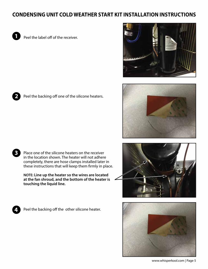
Peel the backing off the other silicone heater.
1
2
3
4

Page 6 | 1-800-343-9463 LASS.PS8000 051515
Place the other silicone heater on the receiver in the location shown. The heater will not adhere completely, there are hose clamps installed later in these instructions that will keep them firmly in place.
Note: Line up the heater so the wires are directed toward the fan shroud, and the back edge of the heater is touching the back edge of the other heater, as shown.
Slide the hose clamps on the receiver over the silicone heaters. One at the top of the heaters and one at the bottom. Secure in place as shown.
Wrap the spring from the Thermal Switch Assembly around the liquid line and secure the clasp of the spring to the thermal switch as shown.
Slide the thermal switch to the location shown
5
6
7
8
Thermal Switch Assembly

www.whisperkool.com | Page 7
Connect the blue disconnect labeled T to the bottom terminal on the thermal switch.
Using a Phillips head screw driver remove the screw on the front edge of the electrical box.
Using a Phillips head screw driver remove the screw on the back edge of the electrical box.
Lift the top and remove it from the electrical box.
9
10
11
12

Page 8 | 1-800-343-9463 LASS.PS8000 051515
Secure both wires into the H1 lever connector.
Using a flat head screw driver loosen the six terminal screws outlined in red, and remove the wires from the terminals.
Cut the zip tie holding the high and low pressure wires.
Remove the adhesive backing from the bottom of the Magnacraft Relay Assembly.
13
16
14
15

www.whisperkool.com | Page 9
Place the Magnacraft Relay Assembly inside the electrical box in the orientation shown. Press the relay assembly firmly in place.
Remove the adhesive backing from the Omron Relay Assembly.
Place the Omron Relay Assembly in the electrical box in the orientation shown. Press the relay assembly firmly in place.
Using a flat head screw driver remove the cable tie holder.
17
18
19
20

Page 10 | 1-800-343-9463 LASS.PS8000 051515
Remove the adhesive backing from the bypass timer.
Place the bypass timer inside the electrical box in the orientation shown. Press the relay assembly firmly in place.
Route the #10 wire with the blue disconnect labeled T down through the cord squeeze.
Connect the blue disconnect labeled T from the #10 wire to the top terminal on the thermal switch.
21
22
23
24

www.whisperkool.com | Page 11
Route the white wires from the heaters up into the electrical box through the cord squeeze.
Pull the slack out of the wires and zip tie them in the locations shown.
Zip tie the wires to the fan shroud as shown.
Connect the #9 wire with the blue disconnect labeled 6 to the #6 terminal on the Omron Relay.
25
26
27
28

Page 12 | 1-800-343-9463 LASS.PS8000 051515
Zip tie one of the high pressure switch wires and low pressure switch wires together.
Blue Wires: low pressure switch.Black Wires with butt splice: high pressure switch.
Secure one low pressure switch wire and one high pressure switch wire inside the H1 lever connector.
Blue Wires: low pressure switch.Black Wires with butt splice: high pressure switch.
Zip tie the wires going into the N1 and H1 lever connectors as shown.
Connect the #2 wire with the red disconnect labeled 1 to the #1 terminal on the bypass timer.
29
30
31
32

www.whisperkool.com | Page 13
Connect the #13 wire with the red disconnect labeled 2 to the #2 terminal on the bypass timer.
Connect the other end of the #13 wire with the blue disconnect labeled 4 to the #4 terminal on the Omron relay.
Connect the #5 wire with the red disconnect labeled 3 to the #3 terminal on the bypass timer.
Using the closed end terminal crimp the #1 wire with the remaining low pressure switch wire.
33
34
35
36
6
4
2
2
3
1

Page 14 | 1-800-343-9463 LASS.PS8000 051515
Secure the #4 wire into the #7 terminal on the terminal block.
Secure the white wire from the #3 terminal on the terminal block inside of the N lever connector.
Remove the blue disconnect from the #3 terminal on the Delay on Break Timer.
Crimp the blue disconnect labeled 3 onto the loose wire coming from the Johnson control. (It was disconnected from the terminal block in step 16)
37
38
39
40
www.whisperkool.com | Page 15
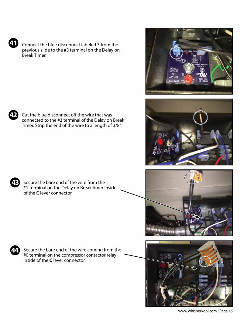
Connect the blue disconnect labeled 3 from the previous slide to the #3 terminal on the Delay on Break Timer.
Cut the blue disconnect off the wire that was connected to the #3 terminal of the Delay on Break Timer. Strip the end of the wire to a length of 3/8”.
41
42
Secure the bare end of the wire from the #1 terminal on the Delay on Break timer inside of the C lever connector.
Secure the bare end of the wire coming from the #0 terminal on the compressor contactor relay inside of the C lever connector.
43
44

Page 16 | 1-800-343-9463 LASS.PS8000 051515
Secure the remaining high pressure switch wire into terminal #2 on the terminal block.
Route the 24v thermostat wires into the electrical box through the cord squeeze.
Connect one of the 24v thermostat wires to the grey #12 wire the using the wire nut provided.
Connect the other 24v thermostat wire to the purple #11 wire the using the wire nut provided.
46
45
47
48

www.whisperkool.com | Page 17
Tidy wires and zip tie in locations shown.
Make sure that no wires are touching the resistor when complete.
Remove the schematic sticker from the electrical box top.
Peel the adhesive backing off of the schematic sticker.
Apply the schematic sticker to the electrical box top as shown.
50
49
51
52
Page 18 | 1-800-343-9463 LASS.PS8000 051515
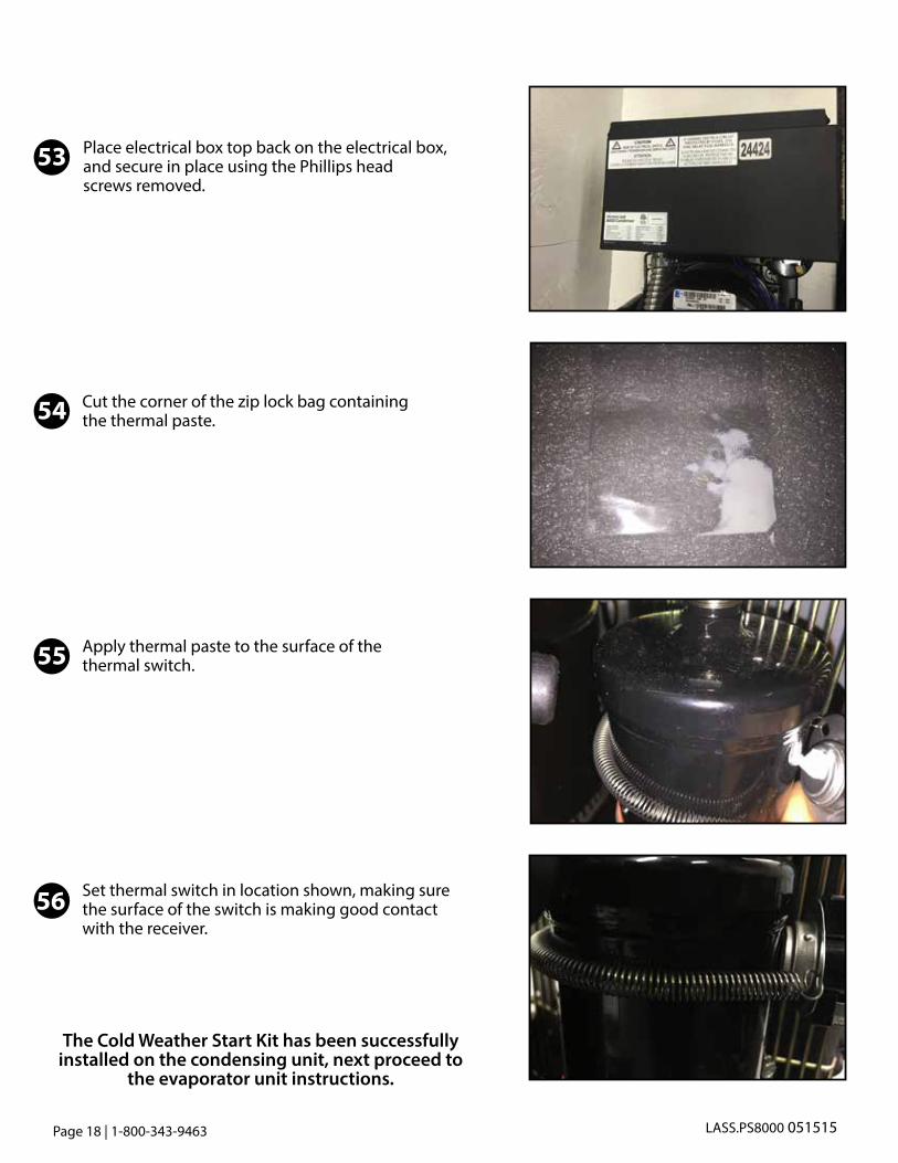
Place electrical box top back on the electrical box, and secure in place using the Phillips head screws removed.
Cut the corner of the zip lock bag containing the thermal paste.
Apply thermal paste to the surface of the thermal switch.
Set thermal switch in location shown, making sure the surface of the switch is making good contact with the receiver.
54
53
55
56
The Cold Weather Start Kit has been successfully installed on the condensing unit, next proceed to
the evaporator unit instructions.

www.whisperkool.com | Page 19
EVAPORATOR UNIT COLD WEATHER START KIT INSTALLATION INSTRUCTIONS
Before beginning the installation process, locate the Evaporator Unit Cold Weather Start Kit. All parts for the Evaporator Unit are located inside of this box.
Open box and remove the 24v transformer and the zip lock bag.
The kit will include five zip ties, four lever connectors, one 6/32 kep nut, and one 120v/24v step down transformer.
Using a Phillips head screw driver loosen the 2 Phillips head screws on the front panel. (Note: The screws do not come out of the panel.)
1
2
3
4

Page 20 | 1-800-343-9463 LASS.PS8000 051515
Wall Mounted UnitsPull front panel away from the unit to remove it. Set panel aside.
Ducted UnitsUsing a Phillips Head Screw driver loosen the 4 screws on the ducting panel, make sure screw comes all the way out of the housing of the unit. (Note: The screws do not come out of the panel.) Pull ducting panel away from the unit to remove it.
Remove the panel.
Remove the thumbscrew by rotating it counter clockwise. (Set thumbscrew aside for later use.)
5
6
7
8

www.whisperkool.com | Page 21
Pull electrical panel out and let hang as shown.
Remove the backing from the double sided tape on the bottom and side edges of the transformer.
Place flange of the transformer between the control box and the flange of the electrical panel, place the other flange underneath the grommet. Press transformer firmly in place.
Locate one of the white wires coming out of the push connector. Cut one white wire and strip both ends to a length of 3/8”.
9
10
12
13
Page 22 | 1-800-343-9463 LASS.PS8000 051515
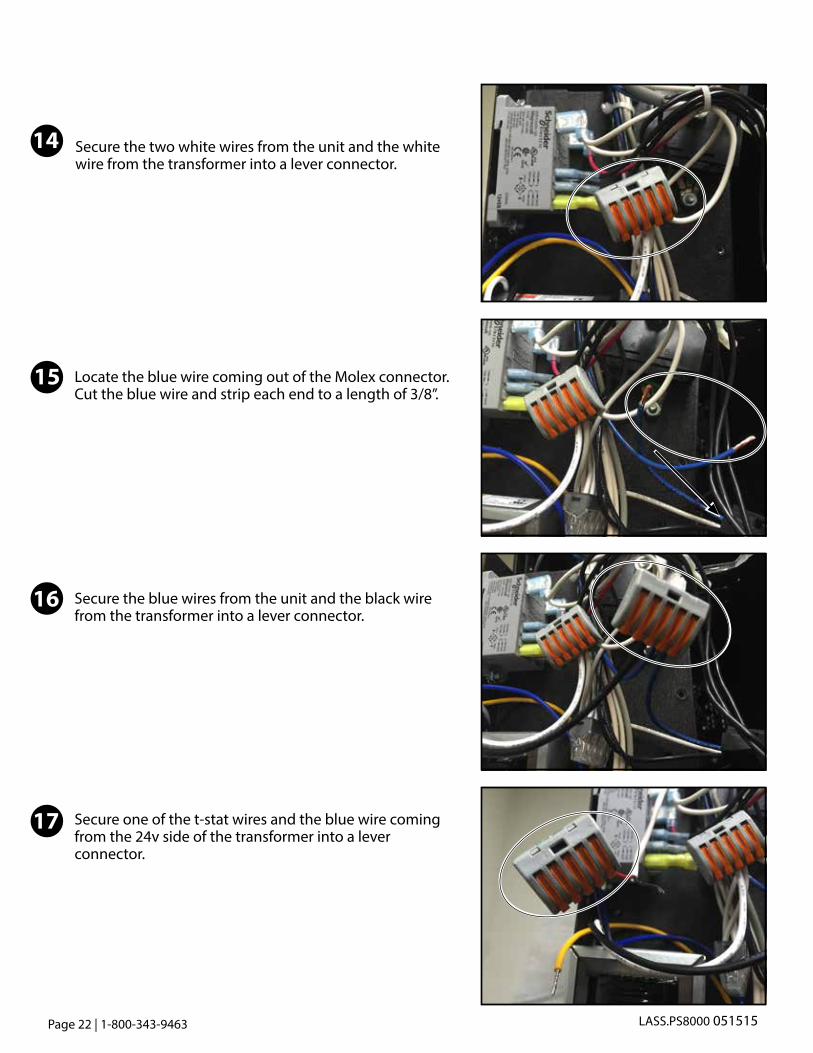
Secure the two white wires from the unit and the white wire from the transformer into a lever connector.
Locate the blue wire coming out of the Molex connector. Cut the blue wire and strip each end to a length of 3/8”.
Secure the blue wires from the unit and the black wire from the transformer into a lever connector.
Secure one of the t-stat wires and the blue wire coming from the 24v side of the transformer into a lever connector.
14
15
16
17

www.whisperkool.com | Page 23
Secure the other t-stat wire and the yellow wire coming from the 24v side of the transformer into a lever connector.
Zip tie wires in locations shown.
Slide the electrical panel back into place and re-install the thumb screw.
Wall Mounted UnitsSecure one of the t-stat wires and the blue wire coming from the 24v side of the transformer into a lever connector.
18
19
20
21

Page 24 | 1-800-343-9463 LASS.PS8000 051515
The Cold Weather Start Kit has been successfully installed on the Evaporator Unit. If the installation process is complete on the condensing unit as well, plug both the condensing unit
and evaporator units back into a power source.
Ducted UnitsPush ducting panel back on unit and tighten the 4 screws on the ducting panel to the unit.
22

www.whisperkool.com | Page 25

LASS.PS8000 051515
WhisperKOOL1738 E. Alpine Ave
Stockton, CA 952051-800-343-9463
www.whisperkool.com