Embed Size (px)
Citation preview

Cold Storage Envelope Specification
Table of Contents November 2007
Page
Part I - General 1.01 Scope of Work ....................................................................................................................................3
1.02 Design Options....................................................................................................................................3 1.03 Quality Assurance ...............................................................................................................................6 1.04 Submittals ...........................................................................................................................................7
1.05 Warranty .............................................................................................................................................8 1.06 Job Conditions ....................................................................................................................................8 1.07 Cautions and Warnings .......................................................................................................................8
Part II - Products
2.01 General ..............................................................................................................................................10 2.02 Membranes........................................................................................................................................10 2.03 EPDM Flashing Accessories.............................................................................................................17 2.04 TPO Flashing Accessories ................................................................................................................17 2.05 Cleaners, Primers, Adhesives and Sealants.......................................................................................19 2.06 Fastening Components......................................................................................................................20 2.07 Insulation/Underlayment...................................................................................................................22 2.08 Underlayment/Cover Boards.............................................................................................................23 2.09 Vapor/Air Retarder Products and Accessories..................................................................................23 2.10 Edgings and Terminations ................................................................................................................24 2.11 Other Carlisle Accessories ................................................................................................................25
Part III – Execution
3.01 General ..............................................................................................................................................26 3.02 Roof Deck Criteria ............................................................................................................................26 3.03 Substrate Preparation ........................................................................................................................27 3.04 Vapor Barrier/Vapor Seal Installation ..............................................................................................27 3.05 Installation of Wood Nailers .............................................................................................................29 3.06 Insulation Installation........................................................................................................................29 3.07 Membrane Placement and Attachment .............................................................................................31 3.08 Flashing.............................................................................................................................................31
Details
603465 – Cold Storage – 11/2007

Cold Storage Envelope Specification
November 2007 Information contained herein describes minimum requirements pertaining to cold storage/freezer facilities by which a Carlisle Roofing and Vapor Seal Warranty can be issued. Due to unique nature of this type of facility, contractors are encouraged to submit project specifications and details for review to ensure an uninterrupted and continuous vapor seal is achieved and the specified warranty prerequisites have been met. PART I GENERAL Refrigerated facilities are any buildings or sections of a building that achieve controlled storage conditions using refrigeration. Two basic storage facilities are coolers that protect commodities at temperatures usually above 32° F and low-temperature rooms (freezers) operating under 32° F to prevent spoilage or to maintain or extend product life. 1.01 SCOPE OF WORK This specification outlines design, application, and products utilized in cold storage and freezer facilities to achieve an uninterrupted or continuous vapor seal and obtain the applicable Carlisle Roofing and Vapor Seal Warranty. The cold storage/freezer envelope system consists of: A. Adhered, Mechanically Fastened, or Ballasted roofing assemblies that incorporate EPDM, TPO, or
FleeceBACK membrane. All components including insulation, adhesives, edging, and associated vapor seal accessories are available from Carlisle for Total System Warranty coverage.
B. Below slab thermal protection/vapor seal – the system is comprised of a continuous vapor barrier,
multiple layers of polystyrene insulation, and a slip-sheet all supplied by Carlisle. Cured Pressure-Sensitive Curb Flashing is used in conjunction with Water Cut-Off Mastic to provide a continuous vapor seal against the insulated exterior wall panel.
C. Exterior Wall Panel Corner Flashing – Pressure-Sensitive uncured Elastoform Flashing is used in
conjunction with HP-250 Primer to provide a vapor seal at the corners of the insulated wall panel system beneath the exterior metal trim.
Refer to Paragraph 1.02, Design Options, for specific information. 1.02 DESIGN OPTIONS A. Roofing Assemblies
Various Carlisle roofing assemblies are available for use on cold storage or freezer facilities. The specifier or the cold storage contractor may select an option perfectly suited for the project conditions,
603465 – Cold Storage – 11/2007 3
regional requirements, and structural load capacity. Sure-Seal black EPDM, Sure-White EPDM or Sure-Weld TPO membranes may be incorporated depending on preference. Ballasted EPDM assemblies are also available for projects where structural load can accommodate such an assembly. Insulation in all assemblies, except Ballasted Assemblies, may be mechanically fastened, attached with a full spray of FAST Adhesive, or set in beads of adhesive.
1. FleeceBACK Adhered Assemblies
a. EPDM – The Sure-Seal/Sure-White FleeceBACK Adhered Roofing System
incorporates Sure-Seal (black) or Sure-White (white-on-black) non-reinforced EPDM membrane laminated to a 55-mil thick non-woven polyester fleece-backing resulting in a total finished sheet thickness of 100-mil (black membrane only) or 115-mil (both black or white). The membrane is fully adhered to an acceptable insulation with a spray applied, two component, low rise FAST Adhesive. Adjoining sheets of membrane are spliced together using 3" or 6" wide Factory-Applied SecurTAPE™ in conjunction with Primer.
b. TPO – The Sure-Weld FleeceBACK Adhered Roofing System incorporates scrim-
reinforced, white, gray or tan Sure-Weld Thermoplastic Polyolefin (TPO) membrane laminated to a 55-mil thick non-woven polyester fleece-backing. The membrane is fully adhered to an acceptable insulation with a spray-applied, two-component, low-rise FAST™ Adhesive. Adjoining sheets of Sure-Weld membrane are overlapped and joined together with a minimum 1-1/2" wide hot air weld.
c. For specific installation requirements pertaining to FleeceBACK Adhered Membrane
Assemblies, refer to the applicable FleeceBACK specification included in the Carlisle technical manual.
2. Conventional Adhered Assemblies
a. EPDM – The Design "A" Adhered Roofing System incorporates Sure-Seal (black) or
Sure-White (white-on-black) 60-mil thick non-reinforced or Sure-Tough™ (black) 45, 60 or 75-mil thick reinforced EPDM membrane. The EPDM membrane is fully adhered to an acceptable insulation with Sure-Seal Bonding Adhesive. Adjoining sheets of EPDM membrane are spliced together using 3" or 6" wide Factory-Applied SecurTAPE™ in conjunction with Primer.
b. TPO – The Sure-Weld Adhered Roofing System incorporates white, gray or tan 45, 60,
72 or 80-mil thick scrim-reinforced Sure-Weld Thermoplastic Polyolefin (TPO) membrane. The membrane is fully adhered to an acceptable insulation with Sure-Weld Bonding Adhesive. Adjoining sheets of membrane are overlapped approximately 2" and joined together with a minimum 1-1/2" wide heat weld.
c. For specific installation requirements pertaining to Conventional Adhered Membrane
Assemblies, refer to the applicable Adhered Roofing System specification included in the Carlisle technical manual.
3. Self Adhering Technology (SAT) TPO
The Carlisle Sure-Weld SAT (Self Adhering Technology) TPO Membrane Application incorporates 45 or 60-mil thick, scrim reinforced, white, Sure-Weld Thermoplastic Polyolefin (TPO) membrane laminated to an elastomeric pressure-sensitive adhesive. The membrane is fully adhered to an acceptable insulation using the factory-applied adhesive and adjoining sheets are overlapped approximately 2" and joined together with a minimum 1-1/2" wide hot air weld.
603465 – Cold Storage – 11/2007 4
For specific installation requirements pertaining to the Carlisle Sure-Weld SAT TPO Membrane Application, refer to “Attachment VI” in the Sure-Weld Adhered Roofing System specification included in the Carlisle technical manual.
4. Mechanically Fastened Assemblies
a. EPDM – The Sure-Seal Reinforced Mechanically-Fastened Roofing System
incorporates Sure-Tough (black) 45, 60 or 75-mil thick reinforced EPDM membrane. The reinforced membrane is mechanically fastened with the appropriate Carlisle Fastener and 2" diameter Fastening Plates or Fastening Bars secured 6" minimum to 12" maximum on center, depending on project criteria, along the center of the membrane splice. Adjoining sheets of EPDM membrane are spliced together using 6" wide Factory-Applied SecurTAPE™ in conjunction with Primer.
b. TPO – The Sure-Weld Mechanically-Fastened Roofing System incorporates white,
tan or gray 45, 60, 72 or 80-mil thick scrim-reinforced, Sure-Weld Thermoplastic Polyolefin (TPO) membrane field sheets. The reinforced TPO membrane is mechanically fastened to the roof deck with the appropriate Carlisle Fasteners and Fastening Plates. Adjoining sheets of Sure-Weld membrane are overlapped and joined together with a minimum 1-1/2" wide heat weld.
c. For specific installation requirements pertaining to Mechanically Fastened Assemblies,
refer to the applicable Mechanically Fastened specification included in the Carlisle technical manual.
5. Ballasted Roofing Assemblies
The Design "B" Loose Laid Ballasted Roofing System incorporates 45 or 60-mil thick Sure-Seal (black) non-reinforced or minimum 60-mil Sure-Tough (black) reinforced EPDM membrane. Both the EPDM membrane and an acceptable insulation are loose laid over the substrate and held in place with a minimum of 10 pounds of ballast per square foot depending upon wind load requirements. Adjoining sheets of EPDM membrane are spliced together using SecurTAPE/Primer. For specific installation requirements pertaining to Ballasted Roofing Assemblies, refer to the Sure-Seal Design “B” Loose-Laid Ballasted Roofing System specification included in the Carlisle technical manual.
B. Below Slab Thermal Protection
No special under-floor treatment is required for refrigerated facilities held above freezing. A below-the-floor vapor retarder, in conjunction with insulation, is needed in facilities held below freezing. Over the cured mud slab, Carlisle Blackline 400 vapor barrier (15-mil in thickness) is installed loosely laid with continuously sealed joints and junctions and overlaid with multiple layers (2 layer minimum) of loosely laid Sure-Seal EPS (40 psi compressive strength) or Foamular 400 extruded polystyrene insulation. The insulation is overlaid with a slip-sheet of 8-mil Carlisle Elephant Skin prior to pouring the concrete floor slab. 1. All overlaps of the slip-sheet and the vapor barrier must be sealed with Carlisle 2" wide TGM
3300 butyl based adhesive sealant, a 2-sided tape. 2. Terminate vapor barrier transition to the exterior wall panel as shown on the appropriate detail
using Carlisle Pressure-Sensitive Curb Flashing and Sure-Seal Water Cut-Off Mastic.
603465 – Cold Storage – 11/2007 5
Caution: To prevent floor frost heaving that may result from moisture in the subsoil, in warmer climates under floor tubes vented to ambient air may be sufficient to prevent heaving. Artificial heating, either by air circulated through under floor ducts or by glycol circulated through plastic pipe, is the preferred method to prevent frost heaving. Electric heating cables installed under the floor can also be used to prevent frost formation. The choice of heating method depends on energy cost, reliability, and maintenance requirements. Air duct systems should be screened to keep rodents out and sloped for drainage to remove condensation.
The concrete slab will contract during pulldown, causing slab/wall joints, contraction joints, and other construction joints to open. At the end of the holding period (i.e., at 35° F), any necessary caulking should be done.
Consult specifier and refer to the ASHRAE Refrigeration Handbook, chapter 13, for specific recommendations.
C. Insulated Metal Wall Panels Corner Junction
To ensure a continuous vapor seal, Pressure-Sensitive uncured Elastoform Flashing (12” wide minimum) in conjunction with HP-250 Primer is used along the entire wall panel corner extending to the wall to roof vapor barrier transition. For freezers, the flashing must also extend to the under floor vapor barrier transition. Cover all exposed flashing with sheet metal trim secured following insulated metal wall panel manufacturer’s recommendation and sealed accordingly.
1.03 QUALITY ASSURANCE Cold storage, more than most construction, requires correct design, quality materials, good workmanship, and close supervision. Design should ensure that proper installation can be accomplished under various adverse job site conditions. Materials must be compatible with each other. Installation must be made by careful workers directed by an experienced, well-trained superintendent. Close cooperation between the general, roofing, insulation, and other contractors increases the likelihood of a successful installation. A. The cold storage/freezer envelope system must be installed by a Carlisle Authorized Applicator in
compliance with shop drawings as approved by Carlisle. There must be no deviations made without PRIOR WRITTEN APPROVAL of Carlisle.
B. Upon completion of the installation, an inspection will be conducted by a Field Service Representative of
Carlisle to ascertain the roofing system has been installed according to Carlisle’s specifications and details.
C. In the United States, the U.S. Public Health Service Food and Drug Administration developed the Food
Code (FDA 1997), which consists of model requirements for safeguarding public health and ensuring that food is unadulterated. The code is a guide for establishing standards for all phases of handling refrigerated foods. These standards must be recognized in the design and operation of refrigerated storage facilities.
D. Regulations of the Occupational Safety and Health Administration (OSHA), Environmental Protection
Agency (EPA), the U.S. Department of Agriculture (USDA), and other standards must also be followed. E. Poor design and shoddy installation can cause moist air leakage into the facility, resulting in frost and ice
formation, energy loss and, eventually, expensive repairs. F. A continuous and uninterrupted vapor/air seal must encapsulate the building structure to prevent warm,
humid air from infiltrating the roof assembly around the perimeter and penetrations. In freezer
603465 – Cold Storage – 11/2007 6

applications the vapor barrier under the floor slab must provide a sealed transition to prevent air leakage at the insulated wall panel/floor junction.
G. Cold storage facilities can change in dimension due to settling, temperature change, and other factors;
therefore, cold storage facilities should be inspected regularly to spot problems early, so that preventive maintenance can be performed in time to avert serious damage.
1.04 SUBMITTALS A. To ensure compliance with Carlisle's minimum warranty requirements, the following projects should be
forwarded to Carlisle for review prior to installation, preferably prior to bid:
1. Projects where the roofing membrane is expected to come in direct contact with petroleum-based products or other chemicals.
2. New construction freezer projects where a below slab thermal protection system is to be installed.
In addition to the roofing warranty, these projects could qualify for a 5-year vapor seal warranty.
3. Projects with extended wind speed coverage that may require different enhancements than those listed as part of the applicable Carlisle roofing system specification.
4. Projects with unusual conditions, special warranty, or those with warranties greater than 20 years.
B. Shop drawings must be submitted to Carlisle by the Carlisle Authorized Roofing Applicator along with a
completely executed Notice of Award (Page 1 of Carlisle's Request For Warranty form) for approval. Approved shop drawings are required for inspection of the roof and on projects where on-site technical assistance is requested.
Shop drawings must include:
1. Outline of roof and size 2. Deck type (for multiple deck types) 3. Location and type of all penetrations 4. Perimeter and penetration details 5. Vapor seal details at roof and floor junction (if applicable)
When field conditions necessitate modifications to the originally approved shop drawings, a copy of the shop drawing outlining all modifications must be submitted to Carlisle for revision and approval prior to inspection and warranty issuance.
C. Notice of Completion (Page 2 of the Carlisle Request for Warranty form)
After project completion, a Notice of Completion must be submitted to Carlisle to schedule the necessary inspection and acceptance of the project prior to issuance of the Carlisle warranty.
D. As-Built Projects (roofing systems installed prior to project approval by Carlisle)
The Carlisle Authorized Applicator may supply Carlisle with an As-Built drawing for a project completed prior to Carlisle's approval. The As-Built drawings:
1. Must conform to Carlisle's most current published specifications and details applicable at the time
of bid.
2. Must be submitted along with a completely executed Notice of Completion.
603465 – Cold Storage – 11/2007 73. Must include the items identified in Paragraph 1.04.B above.

1.05 WARRANTY A. Roofing System Warranty A 10-year Membrane System or 10, 15 or 20-year Total System Warranty is available for the roofing assembly as outlined in the applicable roofing system specification contained in the Carlisle technical manual. B. Vapor Seal Warranty In addition to the above warranties, a Vapor Seal Warranty covering air infiltrations along the perimeter is available for an additional charge when Carlisle metal is used and installed in strict compliance with the Carlisle published details included in this specification.
1. 3-year Vapor Seal Warranty is the maximum available coverage for Ballasted or Mechanically Fastened membrane assemblies.
2. 5-year Vapor Seal Warranty is the maximum available coverage for Adhered and Fleece-Back
membrane assemblies. C. Additional Coverage In addition to the above, special coverage against puncture or hail is also available depending on the type and thickness of membrane used. Refer to Carlisle published specifications or contact Carlisle for requirements. 1.06 JOB CONDITIONS A. All steel beams, columns, and large pipes that project through the insulation should be vapor-sealed and
insulated with a 4-foot high wrap of insulation. The height of insulation at conduits, small pipes, and rods should be four times the regular wall insulation thickness. In both cases, the thickness of insulation on the projection should be half that on the regular wall or ceiling.
B. Coordination between trades is essential to avoid unnecessary rooftop traffic over sections of the roof and
to prevent damage to the membrane. C. Wall construction must be designed so that as few structural members as possible penetrate the insulation
envelope. Insulated panels applied to the outside of the structural frame prevent conduction through the framing. Where masonry or concrete wall construction is used, structural framing must be independent of the exterior wall. The exterior wall cannot be used as a bearing wall unless a suspended insulated ceiling is used.
D. Where interior insulated partitions are required, a double column arrangement at the partition prevents
structural members from penetrating the wall insulation. For satisfactory operation and long life of the insulation structure, envelope construction should be used wherever possible.
1.07 CAUTIONS AND WARNINGS A. Material Safety Data Sheets (MSDS) must be on location at all times during transportation, storage and
application of materials. The applicator shall follow all safety regulations as recommended by OSHA and other agencies having jurisdiction.
B. Wearing slab heating under the dock area in front of the freezer doors will help eliminate moisture at the
door and floor joints.
603465 – Cold Storage – 11/2007 8
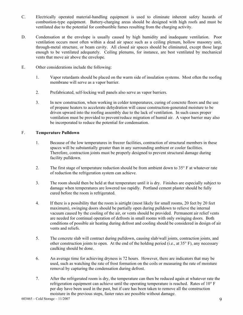
C. Electrically operated material-handling equipment is used to eliminate inherent safety hazards of combustion-type equipment. Battery-charging areas should be designed with high roofs and must be ventilated due to the potential for combustible fumes resulting from the charging activity.
D. Condensation at the envelope is usually caused by high humidity and inadequate ventilation. Poor
ventilation occurs most often within a dead air space such as a ceiling plenum, hollow masonry unit, through-metal structure, or beam cavity. All closed air spaces should be eliminated, except those large enough to be ventilated adequately. Ceiling plenums, for instance, are best ventilated by mechanical vents that move air above the envelope.
E. Other considerations include the following:
1. Vapor retardants should be placed on the warm side of insulation systems. Most often the roofing membrane will serve as a vapor barrier.
2. Prefabricated, self-locking wall panels also serve as vapor barriers. 3. In new construction, when working in colder temperatures, curing of concrete floors and the use
of propane heaters to accelerate dehydration will cause construction-generated moisture to be driven upward into the roofing assembly due to the lack of ventilation. In such cases proper ventilation must be provided to prevent/reduce migration of humid air. A vapor barrier may also be incorporated to reduce the potential for condensation.
F. Temperature Pulldown
1. Because of the low temperatures in freezer facilities, contraction of structural members in these spaces will be substantially greater than in any surrounding ambient or cooler facilities. Therefore, contraction joints must be properly designed to prevent structural damage during facility pulldown.
2. The first stage of temperature reduction should be from ambient down to 35° F at whatever rate
of reduction the refrigeration system can achieve. 3. The room should then be held at that temperature until it is dry. Finishes are especially subject to
damage when temperatures are lowered too rapidly. Portland cement plaster should be fully cured before the room is refrigerated.
4. If there is a possibility that the room is airtight (most likely for small rooms, 20 feet by 20 feet
maximum), swinging doors should be partially open during pulldown to relieve the internal vacuum caused by the cooling of the air, or vents should be provided. Permanent air relief vents are needed for continual operation of defrosts in small rooms with only swinging doors. Both conditions of possible air heating during defrost and cooling should be considered in design of air vents and reliefs.
5. The concrete slab will contract during pulldown, causing slab/wall joints, contraction joints, and
other construction joints to open. At the end of the holding period (i.e., at 35° F), any necessary caulking should be done.
6. An average time for achieving dryness is 72 hours. However, there are indicators that may be
used, such as watching the rate of frost formation on the coils or measuring the rate of moisture removal by capturing the condensation during defrost.
603465 – Cold Storage – 11/2007 9
7. After the refrigerated room is dry, the temperature can then be reduced again at whatever rate the refrigeration equipment can achieve until the operating temperature is reached. Rates of 10° F per day have been used in the past, but if care has been taken to remove all the construction moisture in the previous steps, faster rates are possible without damage.

G. To eliminate flexure of the roof structure or overhead members and simplifies maintenance, cold room
meat tracking, wherever possible, should be erected and supported within the insulated structure, entirely independent of the building itself.
PART II PRODUCTS 2.01 General This section lists and describes products manufactured or marketed by Carlisle. The components of the cold storage envelope are to be products of Carlisle or accepted by Carlisle as compatible. The installation, performance or integrity of products by others, when selected by the specifier and accepted as compatible by Carlisle, is not the responsibility of Carlisle and is expressly disclaimed by the Carlisle Warranty. Consult the Carlisle Technical Data Bulletins for the shelf life limitation, coverage rates and application procedures of each product. Refer to the manufacturer's Material Safety Data Sheets for applicable precautions and warnings prior to the use of any product. 2.02 Membranes A. SURE-SEAL®/SURE-WHITE™ AND SURE-TOUGH™ EPDM MEMBRANES
1. Cured non-reinforced or reinforced EPDM (Ethylene, Propylene, Diene Terpolymer) compounded elastomer.
Non-Reinforced EPDM membrane is available in Sure-Seal (black) or Sure-White (white-on-black). Sure-White membrane must be installed with the white surface facing up and is used for Fully Adhered applications.
2. Pre-KLEENED™ Sure-Seal (black) EPDM Membrane (mica dust has been removed
during manufacturing) is available in 90-mil, 60-mil and 45-mil thicknesses up to 10' wide. Refer to applicable “Application” sections for installation procedures. Factory-Applied SecurTAPE (3" or 6" wide) is also available.
3. Membrane is available in various sizes as outlined below.
a. Non-Reinforced EPDM Membrane - conforms to ASTM D4637, Type I
Sure-Seal (black) 45 or 60-mil thick non-reinforced EPDM membrane - maximum 50' wide, maximum 100' long (additional lengths available dependent on membrane thickness and width) and 90-mil thick non-reinforced EPDM membrane is available maximum 10' wide, maximum 100' long.
Sure-White (white-on-black) 60-mil thick non-reinforced EPDM membrane - maximum 10' wide, maximum 100' long.
b. Reinforced EPDM Membrane (black only) - conforms to ASTM D4637, Type II
Sure-Tough 45, 60 and 75-mil thick reinforced EPDM membrane – 4-1/2', 7', 8' (45 and 60-mil only) or 10' wide, maximum 100' long, reinforced membrane (10' wide 45-mil thick membrane is also available in lengths of 200') with polyester fabric.
603465 – Cold Storage – 11/2007 10Refer to the physical properties listed on the following pages.

SURE-SEAL (Black) 45 and 60-MIL THICK NON-REINFORCED EPDM MEMBRANE STANDARD AND FIRE RETARDANT (FR) 45-mil thick black non-reinforced EPDM membrane is used for Sure-Seal Design "B" Loose Laid Ballasted Roofing Systems 60 or 90-mil thick black non-reinforced FR (Fire Retardant) EPDM membrane is used primarily for the Sure-Seal Adhered Roofing System. This membrane can also be used for the Sure-Seal Design "B" Roofing Systems. Note: Although 60 and 90-mil thick Non-Reinforced EPDM is recommended for Adhered Roofing Systems,
45-mil thick FR Non-Reinforced EPDM may be utilized, if specified.
Typical Physical Property Test Method ASTM SPEC.
(Pass) 45-mil FR
60-mil FR
90-mil FR
Tolerance on Nominal Thickness, % ASTM D 412 ±10 ±10 Tensile Strength, min, psi (MPa) ASTM D 412 1305 (9) 1650 (11.3) Elongation, Ultimate, min, % ASTM D 412 300 480
Tear Resistance, min, lbf/in (kN/m) ASTM D 624 (Die C) 150 (26.3) 200 (35.0)
Factory Seam Strength, min. Modified ASTM D 816
Membrane Rupture
Membrane Rupture
Resistance to Heat Aging* Properties after 4 weeks @ 240°F (116°C) Tensile Strength, min, psi (MPa) Elongation, Ultimate, min, % Tear Resistance, min, lbf/in (kN/m) Linear Dimensional Change, max, %
ASTM D 573
ASTM D 412 ASTM D 412 ASTM D 624 ASTM D 1204
1205 (8.3) 200
125 (21.9) ±1.0
1500 (10.3) 225
215 (37.6) -0.4
Ozone Resistance* Condition after exposure to 100 pphm Ozone in air for 168 hours @ 104°F (40°C) Specimen is at 50% strain
ASTM D 1149 No Cracks No Cracks
Brittleness Temp., max, deg. F (deg. C)* ASTM D 746 -49 (-45) -67 (-55) Resistance to Water Absorption* After 7 days immersion @ 158°F (70°C) Change in mass, max, %
ASTM D 471 +8.0, -2.0 +2.0
Water Vapor Permeance* max, perm
ASTM E 96 (Proc. B or BW) 0.1 .05
Resistance to Outdoor (Ultraviolet) Weathering* Xenon-Arc, 7560 kJ/m2 total radiant exposure at .70 W/ m2 irradiance, 176°F (80º C) black panel temp.
ASTM D 4637 Conditions
No Cracks No Crazing
No Cracks No Crazing
* Not a Quality Control Test due to the time required for the test or the complexity of the test. However, all tests are run on a statistical basis to ensure overall long-term performance of the sheeting.
603465 – Cold Storage – 11/2007 11

SURE-WHITE (White-on-Black) 60-MIL THICK NON-REINFORCED EPDM MEMBRANE The membrane is used for Sure-White Adhered Roofing Systems.
Physical Property Test Method ASTM SPEC. (Pass)
Typical
Tolerance on Nominal Thickness, % ASTM D 412 ±10 ±10 Tensile Strength, min, psi (MPa) ASTM D 412 1305 (9) 1685 (11.6) Elongation, Ultimate, min, % ASTM D 412 300 480 Tear Resistance, min, lbf/in (kN/m) ASTM D 624
(Die C) 150 (26.3) 200 (35.0)
Factory Seam Strength, min. Modified ASTM D 816
Membrane Rupture
Membrane Rupture
Resistance to Heat Aging* Properties after 1 week @ 240°F (116°C) Tensile Strength, min, psi (MPa) Elongation, Ultimate, min, % Tear Resistance, min, lbf/in (kN/m) Linear Dimensional Change, max, %
ASTM D 573
ASTM D 412 ASTM D 412 ASTM D 624 ASTM D 1204
1205 (8.3) 200
125 (21.9) ±1.0
1550 (10.7) 250
185 (32.4) -0.5
Ozone Resistance* Condition after exposure to 100 pphm Ozone in air for 168 hours @ 104°F (40°C) Specimen is at 50% strain
ASTM D 1149 No Cracks No Cracks
Brittleness Temp., max, deg. F (deg. C)* ASTM D 746 -49 (-45) -67 (-55) Resistance to Water Absorption* After 7 days immersion @ 158°F (70°C) Change in mass, max, %
ASTM D 471 +8.0, -2.0 +3.6
Water Vapor Permeance* max., perms ASTM E 96 (Proc. B) 0.1 .05
Resistance to Outdoor (Ultraviolet) Weathering* Xenon-Arc, 7560 kJ/m2 total radiant exposure at .70 W/m2 irradiance, 176°F (80°C) black panel temperature
ASTM D 4637 Conditions
No Cracks No Crazing
No Cracks No Crazing
* Not a Quality Control Test due to the time required for the test or the complexity of the test. However, all tests are run on a statistical basis to ensure overall long-term performance of the sheeting.
603465 – Cold Storage – 11/2007 12

SURE-TOUGH (Black) 45, 60 and 75-MIL THICK REINFORCED EPDM MEMBRANE STANDARD AND FIRE RETARDANT (FR) The membrane is used for:
1. Sure-Seal Adhered Roofing Systems 2. Sure-Seal Mechanically-Fastened Roofing Systems 3. Sure-Seal Design "B" Ballasted (60 and 75 mil only)
Physical Property Test Method ASTM
SPEC. (Pass) Typical
Tolerance on Nominal Thickness, % ASTM D 751 ±10 ±10
Thickness Over Scrim, min, in. (mm) ASTM D 4637
Annex .015 (.381) 45-mil-.016 (.406)
60-mil-.020 (.508) 75-mil-.032 (0.81)
Breaking Strength, min, lbf (N)
ASTM D 751 Grab Method
90 (400) 45 and 60-mil 180 (800)
.075" 230 (1023)
Elongation, Ultimate, min, %
ASTM D 412 Die C
250 ** 45 and 60-mil 480 ** 75-mil 500 **
Tear Strength, min, lbf (N) ASTM D 751 B Tongue Tear 10 (45)
045", .060" 30 (132)
75-mil 70 (311)
Brittleness Temp., max, deg. F (deg. C) * ASTM D 2137 -49 (-45) -60 (-51) Resistance to Heat Aging * Properties after 4 weeks @ 240°F Breaking Strength, min, lbf (N) Elongation, Ultimate, min, % Linear Dimensional Change, max, %
ASTM D 573
ASTM D 751
ASTM D 751 ASTM D 1204
80 (355)
200 ** ±1.0
45 and 60-mil 200 (890)
75-mil 150 (1112)
250 ** -0.7
Ozone Resistance* Condition after exposure to 100 pphm Ozone in air for 168 hours @ 104° F Specimen wrapped around 3" mandrel
ASTM D 1149 No Cracks No Cracks
Resistance to Water Absorption* After 7 days immersion @ 158°F (70°C) Change in mass, max, %
ASTM D 471 +8.0, -2.0 ** +2.0 **
Resistance to Outdoor (Ultraviolet) Weathering* Xenon-Arc, 7560 kJ/m2 total radiant exposure at .70 W/m2 irradiance, 176°F (80°C) black panel temperature
ASTM D 4637 Conditions
No Cracks No Crazing
No Cracks No Crazing
* Not a Quality Control Test due to the time required for the test or the complexity of the test. However, all tests are run on a statistical basis to ensure overall long-term performance of the sheeting.
** Specimens to be prepared from coating rubber compound, vulcanized in a similar method to the reinforced product.
603465 – Cold Storage – 11/2007 13

SURE-SEAL/SURE-WHITE FLEECEBACK MEMBRANE 100 and 115-MIL THICK NON-REINFORCED EPDM MEMBRANE
FIRE RETARDANT (FR) FleeceBACK 100 or 115 membrane incorporates 45 or 60-mil thick Sure-Seal (black) or Sure-White (white-on-black) non-reinforced EPDM laminated to a 55-mil non-woven polyester fleece-backing resulting in a total finished sheet thickness of 100 or 115-mils. A selvage edge (fleece backing does not extend to the edge of sheet) with 3" or 6" wide Factory-Applied SecurTAPE is provided along the length of the membrane for splicing. Membrane is available in widths of 10' and lengths of 50' or 100' and conforms to ASTM Standard D 4637-96, Type III (Fabric-Backed membrane) with the following physical properties:
Physical Property Test Method SPEC. (Pass)
Sure-Seal Typical
Sure-White Typical
Tolerance on Nominal Thickness, % ASTM D 751 ±10 ±10 ±10 Thickness over Fleece, min, in. (mm)
100 mil (2.54 mm) 115 mil (2.92 mm)
ASTM D4637 Annex
.030 (.762) .030 (.762)
.045 (1.143) .060 (1.524)
.045(1.143) .060 (1.524)
Weight 1b/ft2 (kg/m2) 100 mil (2.54 mm) 115 mil (2.92 mm)
0.29 (1.4) 0.38 (1.9)
0.33 (1.6) 0.42 (2.1)
Breaking Strength, min, lbf (N) ASTM D751 Grab Method 90 (400) 200 (890) 200 (890)
Elongation, Ultimate, min, % ASTM D 412 300 ** 500 ** 500 ** Tearing Strength, min, lbf (N) ASTM D 751
B Tongue Tear 10 (45) 45 (200) 45 (200)
Brittleness point, max, °F (°C) ASTM D 2137 -49 (-45) -75 (-59) -75 (-59) Resistance to Heat Aging * Properties after 4 weeks @ 240° F (116°C) for Sure-Seal Properties after 1 week @ 240° F for Sure-White Breaking Strength, min, lbf (N) Elongation, Ultimate, min, % Linear Dimensional Change, max, %
ASTM D 573
ASTM D 751 ASTM D 412
ASTM D 1204
80 (355) 200 ** ±1.0
200 (890) 310 **
-0.7
200 (890) 250 **
-0.7 Ozone Resistance * Condition after exposure to 100 pphm Ozone in air for 168 hours @ 104°F (40°C) Specimen wrapped around 3 inch (7.5 cm) mandrel
ASTM D 1149 No Cracks No Cracks No Cracks
Resistance to Water Absorption * After 7 days immersion @ 158°F (70°C) Change in mass, max, %
ASTM D 471 4.0** 2.0 ** 3.6 **
Resistance to Outdoor (Ultraviolet) Weathering * Xenon-Arc, 7560 kJ/m2 total radiant exposure at 0.70 W/m2 irradiance 176° F (80°C) black panel temperature
ASTM G 155 No Cracks No Crazing
No Cracks No Crazing
No Cracks No Crazing
* Not a Quality Control Test due to the time required for the test or the complexity of the test. However, all tests are run on a
statistical basis to ensure overall long-term performance of the sheeting. ** Specimens prepared from coating rubber compound.
603465 – Cold Storage – 11/2007 14

B. Sure-Weld (TPO) Membranes
Sure-Weld TPO Membrane meets or exceeds the requirements of ASTM D6878, standard specification for Thermoplastic Polyolefin Based Sheet Roofing. In addition to the physical properties listed below, refer to the Sure-Weld Membrane Technical Data Bulletin for Cool Roof Rating Council (CRRC) and LEED™ radiative properties as well as U.S.E.P.A. Toxic Leachate Testing and dynamic puncture resistance.
1. Sure-Weld SAT™ Reinforced Membrane – A nominal 45 or 60-mil reinforced TPO membrane
laminated to an elastomeric Pressure-Sensitive adhesive. Available widths are 5' and 10' by 50' and 100' lengths.
2. Sure-Weld 45 or 60-mil and Sure-Weld EXTRA – 72 or 80-mil thick Reinforced Thermoplastic
Polyolefin (TPO) membrane conforms to the following physical properties. Field membrane sheets are available in rolls 12', 10' or 8' wide by 100' long. Perimeter membrane sheets are available in widths of 6' and 5' (used with 12' and 10' wide field sheets) or 4' (used with 8' wide field sheets) by 100' long. Available in white, gray or tan.
Property (Metric-SI Units) Test Method
Property of Unaged Sheet 45, 60, 72 or 80-mil
Property After Aging (1) 28 days @ 240° F 45, 60, 72 or 80-mil
Tolerance on Nominal Thickness, % ASTM D 751 ±10 45-mil
0.018 (0.457) ±10 60-mil
0.024 (0.610) ±10
Thickness Over Scrim, min, in. (mm) ASTM D 6878 Optical Method (Avg. 3 areas)
72-mil 0.030 (0.762)
±10
80-mil 0.030 (0.762)
±10
Solar Reflectance (albedo X 100), % (Min. for ENERGY STAR approval is 65%)
Solar Spectrum Reflectometer
White - 87 Typ. Tan - 68 Typ.
Emittance, infrared ASTM E 408 0.92 Typ. 45-mil
225 (1.0) Min. 320 (1.4) Typ.
60-mil 250 (1.1) Min. 360 (1.6) Typ.
45-mil 225 (1.0) Min. 320 (1.4) Typ.
60-mil 250 (1.1) Min. 360 (1.6) Typ. Breaking Strength, min, lbf (kN)
ASTM D 751 Grab Method
72-mil 350 (1.6) Min. 400 (1.8) Typ.
80-mil 350 (1.6) Min. 425 (1.9) Typ.
72-mil 350 (1.6) Min. 400 (1.8) Typ.
80-mil 350 (1.6) Min. 425 (1.9) Typ.
Elongation at Break of Fabric, min, % ASTM D 751 25 Typ. 25 Typ. Tearing Strength, min, lbf (N) 8" by 8" specimen
ASTM D 751 B Tongue Tear
55 (245) Min. 130 (578) Typ.
55 (245) Min. 130 (578) Typ.
Brittleness Point, max, °F (°C) ASTM D 2137 -40 (-40) Min.
-50 (-46) Typ.
Linear Dimensional Change (shrinkage), % ASTM D 1204 +/- .05 max. -0.2 Typ.
Ozone Resistance, 100 pphm, 168 hours ASTM D 1149 No Cracks No Cracks
Resistance to Water Absorption After 7 days immersion @ 158°F (70°C) Change in mass, max, %
ASTM D 471 4.0 Max. 2.0 Typ.
Resistance to microbial surface growth, rating (1 is very poor, 10 is no growth)
ASTM D 3274 2 yr. S. Florida
9 – 10 Typ.
Field seam strength, lbf/in. (kN/m) Seam tested in peel
ASTM D1876 25 (4.4) Min. 60 (10.5) Typ.
Water vapor permeance, Perms ASTM E 96 0.10 Max. 0.05 Typ.
45-mil 250 (1.1) Min. 325 (1.4) Typ.
60-mil 300(1.3) Min. 350 (1.6) Typ.
Puncture resistance, lbf (N) FTM 101C Method 2031 72-mil
350 (1.6) Min. 400 (1.) Typ.
80-mil 400 (1.8) Min. 450 (2.0) Typ.
Resistance to xenon-arc Weathering (2) Xenon-Arc, 10,080 kJ/m2 total radiant exposure, Visual condition at 10X
ASTM G 155 0.70 W/m2 80°C B.P.T.
No Cracks No loss of breaking or tearing strength
(1) Aging conditions are 28 days at 240° F (116° C) equivalent to 400 days at 176° F (80° C) for breaking strength, elongation, tearing strength, linear dimensional change, ozone and puncture resistance.
(2) Approximately equivalent to 8000 hours exposure at 0.35W/m2.
603465 – Cold Storage – 11/2007 15

SURE-WELD FLEECEBACK 100 and 115-MIL THICK TPO MEMBRANE
Sure-Weld FleeceBACK 100 or 115 membrane incorporates 45 or 60-mil thick Thermoplastic Polyolefin (TPO) membrane laminated to a 55 mil non-woven fleece backing resulting in a total finished sheet thickness of 100 or 115-mils. Membrane sheets are available in rolls 12' or 6' wide by 50' or 100' long. Sure-Weld FleeceBACK Membrane is available in white, gray or tan and conforms to the following.
Property Test Method Property of Unaged Sheet
Property After Aging (1)
28 days @ 240° F Thickness of reinforced sheet over fleece, in. (mm) tolerance is ±10 ASTM D 751 0.045 (1.14 – FB 100
0.060 (1.52 – FB 115
Breaking Strength, min, lbf (kN) ASTM D 751 Grab Method
300 (1.3) min. - FB100 400 (1.8) typical - FB100
400 (1.8) min. FB115
500 (2.2) typical FB115
300 (1.3) min. - FB100 400 (1.8) typical - FB100
400 (1.8) min. FB115
500 (2.2) typical FB115 Elongation at break of internal fabric,% ASTM D 751 25 typical 25 typical
Tearing Strength, min, lbf (N) 8" by 8" specimen ASTM D 751 B Tongue Tear
55 (245) Min. 130 (578) typical
55 (245) Min. 130 (578) typical
Brittleness Point, °F (°C) ASTM D 2137 -40 (-40) Min. -50 (-46) Typical
Linear Dimensional Change (shrinkage), % ASTM D 1204 +/- 0.5 Max. -0.2 typical
Ozone Resistance, 100 pphm, 168 hours ASTM D 1149 No Cracks No Cracks Resistance to Water Absorption After 7 days immersion @ 158°F (70°C) Change in mass, %
ASTM D 471 (fleece removed,
edges sealed)
4.0 Max. 2.0 typical
Resistance to microbial surface growth, rating (1 is very poor, 10 is no growth)
ASTM D 3274 2 yr. S. Florida
9 – 10 typical
Field seam strength, lbf/in. (kN/m) Seam tested in peel ASTM D1876
40 (7.0) Min.
60 (10.5) typical
Water vapor permeance, Perms ASTM E 96 0.10 Max. 0.05 typical
Puncture resistance, lbf (N) FTM 101C Method 2031
350(1.6) min. - FB100 450 (2.0) typical - FB100
400 (1.8) min. FB115
500 (2.2) typical FB115
350(1.6) min. - FB100 450 (2.0) typical - FB100
400 (1.8) min. FB115
500 (2.2) typical FB115 Resistance to xenon-arc Weathering (2) Xenon-Arc, 17,640 kJ/m2 total radiant exposure visual condition at 10X
ASTM G 155 0.70 W/m2
80°C B.P.T.
No Cracks No loss of breaking or
tearing strength
(1) Aging conditions are 28 days at 240° F (116° C) equivalent to 400 days at 176° F (80° C) for breaking strength, elongation,
tearing strength, linear dimensional change, ozone and puncture resistance. (2) Approximately equivalent to 14,000 hours exposure at 0.35 W/m2 irradiance. B.P.T. is black panel temperature.
603465 – Cold Storage – 11/2007 16

2.03 EPDM FLASHING ACCESSORIES A. Sure-Seal (black)/Sure-White (white) Pressure-Sensitive Pipe Seals with Factory-Applied SecurTAPE
on the deck flange are available for use with Sure-Seal/Sure-White Roofing Systems:
1. Sure-Seal Pressure-Sensitive Pipe Seals are available in sizes - 1/2" to 3", 4" to 6" and 1" to 6". 2. Sure-White Pressure-Sensitive Pipe Seals are available in one size - 1" to 6".
B. Sure-Seal Pourable Sealer Pocket – A pre-fabricated Pourable Sealer Pocket which consists of a 2"
wide plastic support strip with Factory-Applied, adhesive backed uncured Elastoform Flashing; available in 4", 6" and 8" diameters. Available in black only.
C. Sure-Seal Inside/Outside Corner – A 7" by 9" precut 60-mil thick Elastoform Flashing with a 35-mil
Factory-Applied SecurTAPE. Available in black only. D. Sure-Seal/Sure-White Pressure-Sensitive Curb Flashing – A 60-mil thick, 20" wide by 50' long cured
EPDM membrane with 5" wide Factory-Applied SecurTAPE along one edge to be used to flash curbs/skylights, etc. Sure-Seal Pressure-Sensitive curb flashing can also be used for vapor barrier transition for below slab applications. Refer to applicable Cold Storage Detail.
E. Sure-Seal Pressure-Sensitive Overlayment Strip – A nominal 40-mil black, semi-cured EPDM
membrane laminated to a nominal 35-mil cured, Factory-Applied SecurTAPE. Available in 6", 9" and 12" widths and 100' long rolls used to flash gravel stops, metal edgings and Seam Fastening Plates used for additional membrane securement.
F. Sure-Seal/Sure-White Pressure-Sensitive Cured Cover Strip – A 6", 9" and 12" wide by 100' long
Sure-Seal or Sure-White 60-mil cured EPDM membrane laminated to a nominal 35-mil cured Factory-Applied SecurTAPE. The Cured Cover Strip is ideal for stripping in seams, flash gravel stops, metal edging and Carlisle Seam Fastening Plates.
G. Sure-Seal Pressure-Sensitive "T" Joint Covers – A factory cut 6" X 6" uncured 60-mil thick EPDM
flashing (with rounded corners) laminated to a nominal 35-mil Factory-Applied SecurTAPE, used to overlay field splice intersections and to cover field splices at angle changes.
H. Sure-Seal/Sure-White Uncured EPDM Elastoform Flashing® – An easily formed, 60-mil thick Sure-
Seal or Sure-White uncured EPDM membrane. Sure-Seal Elastoform Flashing is available in widths of 6", 9", 12", 18" and 24" and lengths of 100'. Sure-White Uncured Flashing is available in 6" and 12" widths only.
Sure-Seal uncured flashing is to be used in conjunction with Sure-Seal (black) Roofing Systems and the Sure-White uncured flashing is to be used in conjunction with Sure-White (white-on-black) Roofing Systems. Sure-Seal/Sure-White uncured Elastoform Flashing is used mainly to flash inside and outside corners, pipes, scuppers and field fabricated pourable sealer pockets when the use of Carlisle pre-fabricated flashing accessories is not feasible.
I. Sure-Seal/Sure-White Pressure-Sensitive Uncured Elastoform Flashing – A 9" or 12" wide by 50'
long, 60-mil thick uncured EPDM Flashing laminated to a 35-mil Factory-Applied SecurTAPE used in conjunction with Sure-Seal Primer as an option to Sure-Seal Elastoform Flashing. This product can also be used as a vapor barrier transition at inside and outside corners on vertical exterior insulated wall panels.
2.04 TPO FLASHING ACCESSORIES
603465 – Cold Storage – 11/2007 17
A. Pressure-Sensitive Cover Strip – A nominal 40-mil thick non-reinforced TPO membrane laminated to nominal 35-mil thick cured synthetic rubber pressure-sensitive adhesive used in conjunction with HP-250

Primer to strip in flat metal flanges (i.e., drip edges or rows of fasteners and plates). Available in rolls 6" wide by 100' long in colors of white, gray or tan. Not for use on 20-year Warranty projects.
B. TPO Pressure-Sensitive RUSS – A nominal 6" and 10" wide, .045" thick reinforced TPO membrane
with nominal 3" wide 35-mil thick cured synthetic rubber pressure-sensitive adhesive laminated along one end on 6" wide RUSS and along both ends on 10" wide RUSS. Used in conjunction with HP-250 Primer. 6" wide RUSS is used as a base membrane securement along walls, curbs, etc.; 10" wide RUSS is used to form perimeter sheets on Mechanically-Fastened Systems.
C. TPO T-Joint Covers – A 60-mil thick non-reinforced TPO flashing cut into a 4.5" diameter circle used
to seal step-offs at splice intersections. Installation is mandatory on all 60, 72,and 80-mil TPO systems and on 45-mil systems where step-offs have not been properly sealed. Packaged in boxes of 100. Available in white, tan or gray.
D. Sure-Weld Heat Weldable Walkway Rolls – Consists of recycled Sure-Weld Membrane offering
superior tear, puncture and weather resistance and designed to protect Sure-Weld membrane in those areas exposed to repetitive foot traffic or other hazards. Walkway material may be heat welded to Sure-Weld membrane using an automated heat welder or hand held heat welder. Walkway Rolls are 30" wide by 50' long and are nominal 120 mils thick. Available in white only.
E. TPO Curb Wrap Corners – Fabricated flashings are made of 45-mil thick reinforced Sure-Weld
membrane designed to reduce installation time to flash a curb when compared to conventional methods. Each corner is fabricated with a 6" wide base flange and a 12" overall height. Six sizes are available to fit curbs up to 6' by 6' in size. One curb requires 4 corners for a complete installation. TPO Curb Corners are packaged in boxes of twelve. Custom sizes are available as a special order product requiring lead-time.
F. Pipe Flashings – A pre-molded white, gray or tan pipe flashing used for pipe penetrations. Available for
1" – 6" diameter pipes with clamping rings included. G. Split Pipe Seals – A prefabricated flashing consisting of 45-mil thick reinforced Sure-Weld Membrane
for pipes 1" – 6" in diameter. A split (cut) and overlapped tab are incorporated to allow the pipe seal to be opened and wrapped around the pipe when it is not possible to pull a standard pipe flashing over a round penetration. Custom sizes are available as a special order product requiring lead-time.
H. TPO Square Tubing Wraps – Fabricated flashings made of 45-mil thick reinforced Sure-Weld
membrane for square tubing. A split (cut) and overlap tab are incorporated into these parts to allow the seals to be opened and wrapped around a square penetration. Available for 3", 4", 5" and 6" diameter square tubing.
I. Molded TPO Sealant Pockets – A pre-fabricated, interlocking, 2-piece, injection molded, flexible
pocket with a rigid polypropylene vertical wall and pre-formed deck flanges. Used in conjunction with Thermoplastic One-Part Pourable Sealer for waterproofing pipe clusters or other odd shaped penetrations. Available in white, gray or tan. Forms a 7-1/2" by 6" oval when completed.
J. Pre-Fabricated Sealant Pockets – A two-piece, pre-fabricated sealant pocket that utilizes reinforced
TPO membrane and coated metal to form a rigid, oversized sealant pocket with a weldable horizontal deck flange. Available in 12" (total volume of 1.87 gallons), 16" (total volume of 2.77 gallons) and 20" (total volume of 3.81 gallons). Packaged 2 per carton and available in white only. Refer to the applicable Technical Data Bulletin for dimensions and installation instructions.
603465 – Cold Storage – 11/2007 18
K. Sealant Pocket Extension Legs – Designed for use with the TPO Molded Sealant Pocket and the Pre-Fabricated Sealant Pocket to extend the length in increments of 10". Fabricated from 45-mil thick reinforced TPO membrane and TPO coated metal. Can be used full length, cut to size for customized lengths or welded to each other for extra long applications. Packaged 10 legs per carton and available in white only.
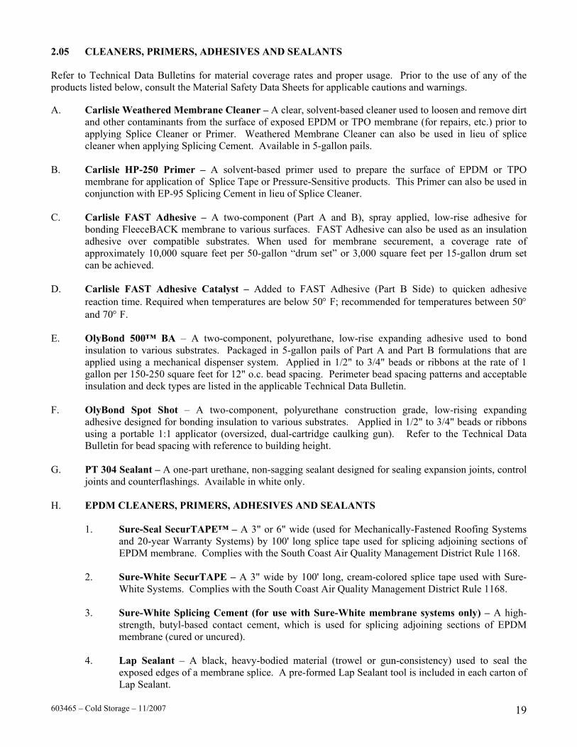
2.05 CLEANERS, PRIMERS, ADHESIVES AND SEALANTS
Refer to Technical Data Bulletins for material coverage rates and proper usage. Prior to the use of any of the products listed below, consult the Material Safety Data Sheets for applicable cautions and warnings. A. Carlisle Weathered Membrane Cleaner – A clear, solvent-based cleaner used to loosen and remove dirt
and other contaminants from the surface of exposed EPDM or TPO membrane (for repairs, etc.) prior to applying Splice Cleaner or Primer. Weathered Membrane Cleaner can also be used in lieu of splice cleaner when applying Splicing Cement. Available in 5-gallon pails.
B. Carlisle HP-250 Primer – A solvent-based primer used to prepare the surface of EPDM or TPO
membrane for application of Splice Tape or Pressure-Sensitive products. This Primer can also be used in conjunction with EP-95 Splicing Cement in lieu of Splice Cleaner.
C. Carlisle FAST Adhesive – A two-component (Part A and B), spray applied, low-rise adhesive for
bonding FleeceBACK membrane to various surfaces. FAST Adhesive can also be used as an insulation adhesive over compatible substrates. When used for membrane securement, a coverage rate of approximately 10,000 square feet per 50-gallon “drum set” or 3,000 square feet per 15-gallon drum set can be achieved.
D. Carlisle FAST Adhesive Catalyst – Added to FAST Adhesive (Part B Side) to quicken adhesive
reaction time. Required when temperatures are below 50° F; recommended for temperatures between 50° and 70° F.
E. OlyBond 500™ BA – A two-component, polyurethane, low-rise expanding adhesive used to bond
insulation to various substrates. Packaged in 5-gallon pails of Part A and Part B formulations that are applied using a mechanical dispenser system. Applied in 1/2" to 3/4" beads or ribbons at the rate of 1 gallon per 150-250 square feet for 12" o.c. bead spacing. Perimeter bead spacing patterns and acceptable insulation and deck types are listed in the applicable Technical Data Bulletin.
F. OlyBond Spot Shot – A two-component, polyurethane construction grade, low-rising expanding
adhesive designed for bonding insulation to various substrates. Applied in 1/2" to 3/4" beads or ribbons using a portable 1:1 applicator (oversized, dual-cartridge caulking gun). Refer to the Technical Data Bulletin for bead spacing with reference to building height.
G. PT 304 Sealant – A one-part urethane, non-sagging sealant designed for sealing expansion joints, control
joints and counterflashings. Available in white only. H. EPDM CLEANERS, PRIMERS, ADHESIVES AND SEALANTS
1. Sure-Seal SecurTAPE™ – A 3" or 6" wide (used for Mechanically-Fastened Roofing Systems and 20-year Warranty Systems) by 100' long splice tape used for splicing adjoining sections of EPDM membrane. Complies with the South Coast Air Quality Management District Rule 1168.
2. Sure-White SecurTAPE – A 3" wide by 100' long, cream-colored splice tape used with Sure-
White Systems. Complies with the South Coast Air Quality Management District Rule 1168.
3. Sure-White Splicing Cement (for use with Sure-White membrane systems only) – A high-strength, butyl-based contact cement, which is used for splicing adjoining sections of EPDM membrane (cured or uncured).
4. Lap Sealant – A black, heavy-bodied material (trowel or gun-consistency) used to seal the
exposed edges of a membrane splice. A pre-formed Lap Sealant tool is included in each carton of Lap Sealant.
603465 – Cold Storage – 11/2007 19

a. Sure-Seal Lap Sealant – Black sealant for use with Sure-Seal (black) Roofing Systems.
b. Sure-White Lap Sealant – White sealant for use with Sure-White (white-on-black) Roofing Systems.
5. 90-8-30A Bonding Adhesive – A high-strength, yellow colored, synthetic rubber adhesive used
for bonding Sure-Seal/Sure-White EPDM membranes to various surfaces. 6. Pourable Sealer – A black, two-component, solvent-free, polyurethane based product used for
tie-ins and as a sealant around hard-to-flash membrane penetrating objects such as clusters of pipes and for a daily seal when the completion of flashings and terminations cannot be completed by the end of each work day.
7. Sure-Seal One-Part Pourable Sealer – A black, one-component, moisture curing, elastomeric
polyether sealant used for attaching lightning rod bases and ground cable clips to the membrane surface and as a sealant around hard-to-flash penetrations such as clusters of pipes.
I. TPO CLEANERS, PRIMERS, ADHESIVES AND SEALANTS
1. Sure-Weld Bonding Adhesive – A high-strength, synthetic rubber adhesive used for bonding Sure-Weld membrane to various surfaces. The adhesive is applied to both the membrane and the substrate at a coverage rate of approximately 60 square feet per gallon per finished surface (includes coverage on both surfaces).
2. Sure-Weld Low VOC Bonding Adhesive – An alternate, high-strength, adhesive using a blend
of VOC exempt and non-exempt solvent which complies with the state of California Clean Air Act of 1988 (updated in 1997).
3. Aqua Base 120 Bonding Adhesive – A semi pressure-sensitive, water based adhesive used as a
two-sided contact adhesive. Coverage rate is 120 square feet per gallon finished surface (applied to membrane and substrate).
4. Cut-Edge Sealant – A white or clear colored sealant used to seal cut edges of reinforced Sure-
Weld membrane. A coverage rate of approximately 225 - 275 linear feet per squeeze bottle can be achieved when a 1/8" diameter bead is applied.
5. Thermoplastic One-Part Pourable Sealer – A one-part, moisture curing, elastomeric polyether
sealant used to fill TPO Molded Pourable Sealant Pockets. Packaged in 4, 2-liter foil pouches inside a reusable plastic bucket. 1 pouch will fill 2 TPO Molded Pourable Sealant Pockets.
2.06 FASTENING COMPONENTS
Refer to specific application requirements in the Carlisle Specification and Detail Manual.
A. HP Fastener – A threaded, black epoxy electro-deposition coated (E-Coat) fastener for use with
steel, wood plank, minimum 15/32" thick plywood or minimum 7/16" thick oriented strand board. B. InsulFast Fasteners – A threaded, Phillips head fastener used with 3" diameter Carlisle Insulation
Plates. Used for insulation attachment into steel or wood decks. C. Pre-Assembled ASAP Fasteners – Carlisle's InsulFast Fastener and pre-assembled 3" diameter
Plastic Insulation Plate used for insulation attachment on Adhered and Mechanically-Fastened Roofing Systems. Installed using Olympic Fastening Tools.
603465 – Cold Storage – 11/2007 20
D. CD-10 Concrete Fastener – A hammer-driven, non-threaded, black epoxy electro-deposition coated (E-Coat) fastener for use with structural concrete decks rated 3,000 psi or greater.

E. HD 14-10 Concrete Fastener – A #14 threaded fastener used for minimum 3,000 psi concrete decks. F. HP-X Fasteners – A heavy-duty #15 threaded fastener with a Phillips head for use primarily on
Adhered assemblies where increased pullout resistance is necessary. Used for steel and wood decks. G. HP-Xtra Fastener – An oversized diameter #21 (.315") steel threaded fastener used in conjunction
with Piranha Xtra Plates for membrane securement into minimum 22 gauge steel or wood decks. H. HP Term Bar Nail-In – A 1-1/4" long expansion anchor with threaded drive pin used for fastening
Sure-Seal Termination Bar or Seam Fastening Plates to concrete, brick or block walls. The fastener is set by hammering the drive pin into place.
I. Seam Fastening Plates – A 2" diameter metal plate used for insulation attachment on Mechanically-
Fastened Roofing Systems or membrane securement on Adhered Roofing Systems in conjunction with the appropriate Carlisle Fastener.
J. Insulation Fastening Plates – A nominal 3" diameter metal plate used for insulation attachment in
conjunction with the appropriate Carlisle Fastener. K. EPDM FASTENING COMPONENTS
1. Sure-Seal Pressure-Sensitive RUSS™ (Reinforced Universal Securement Strip) – A 6" or 9" wide, nominal 45-mil thick clean, cured reinforced EPDM black membrane with 3" wide Factory-Applied SecurTAPE laminated along one edge for the 6" wide RUSS and along both edges for the 9" wide RUSS.
a. 6" wide Pressure-Sensitive RUSS is used horizontally or vertically at the base of
walls, curbs, etc., in conjunction with 2" diameter Fastening Plates below the EPDM deck membrane for additional membrane securement (Polymer Seam Plates are required for Mechanically-Fastened Roofing Systems over steel decks).
b. 9" wide Pressure-Sensitive RUSS is utilized for perimeter membrane securement
on Sure-Seal Mechanically-Fastened Roofing Systems.
2. Sure-White Pressure-Sensitive RUSS (Reinforced Universal Securement Strip) – A 6" wide, nominal 45-mil thick clean, cured, white reinforced EPDM membrane with 3" wide Factory-Applied SecurTAPE laminated along one edge. Used on Sure-White Adhered Roofing Systems.
3. HP Polymer Seam Plate – A 2" diameter plastic barbed fastening plate used with Carlisle
HP Fasteners for membrane and Pressure-Sensitive RUSS securement for Mechanically-Fastened Roofing Systems over steel roof decks. (Available pre-assembled.)
4. Seam Fastening Plate – A 2" diameter metal fastening plate used for membrane and RUSS
attachment on Mechanically-Fastened Roofing Systems over wood or structural concrete decks. Seam Fastening Plates are also used in conjunction with RUSS or EPDM membrane for additional membrane securement on Adhered or Ballasted Roofing Systems. This plate may be used for insulation attachment on Mechanically-Fastened Roofing Systems.
5. Insulation Fastening Plate – A nominal 3" diameter FM approved metal plate used for
insulation attachment in conjunction with Sure-Seal Fasteners.
603465 – Cold Storage – 11/2007 21

L. TPO FASTENING COMPONENTS
1. Piranha Plates – A 2-3/8" diameter metal barbed fastening plate used with Carlisle HP-X, CD-10 or HD 14-10 Fasteners for membrane securement. This plate can be used for insulation securement.
2. Piranha Xtra Plates – A 2-3/8" diameter metal barbed fastening plate with an oversized hole
for use with Carlisle HP-Xtra Fasteners for membrane securement.
3. TPO Pressure-Sensitive RUSS – A nominal 6" and 10" wide, .045" thick reinforced TPO membrane with nominal 3" wide 35-mil thick cured synthetic rubber pressure-sensitive adhesive laminated along one end on 6" wide RUSS and along both ends on 10" wide RUSS. Used in conjunction with HP-250 Primer. 6" wide RUSS is used as a base membrane securement along walls, curbs, etc.; 10" wide RUSS is used to form perimeter sheets on Mechanically-Fastened Systems.
2.07 INSULATION/UNDERLAYMENT
SURE-SEAL INSULATIONS Thickness
Brand Name Board Size Inch cm
R-Value @40° F (5° C)
Minimum Compressive Strength (1)
Minimum Density
Sure-Seal EPS (Expanded Polystyrene) For use with Ballasted, as an underlayment with cover board or for Mechanically-Fastened/ Adhered Systems and as a floor insulation. Thicker, Tapered and higher density boards are available upon request.
4' X 4'
(1.2 m X 1.2 m) or
4' X 8' (1.2 m X 2.4 m)
1"
1-1/2" 2" 3" 4" 5"
2.5 3.8 5
7.6 10.1 12.7
4.17 6.25 8.33 12.50 16.67 20.83
13 psi 16 psi 20 psi 40psi
1 pcf 1.25 pcf 1.5 pcf 2 pcf
Insulfoam® SP (Expanded Polystyrene) For use with TPO Mechanically-Fastened Roofing Systems
4' X 4' (1.2 m X 1.2 m)
or 4' X 8'
(1.2 m X 2.4 m)
1" 1-1/2"
2" 3" 4" 5"
2.5 3.8 5
7.6 10.1 12.7
4.17 6.25 8.33 12.50 16.67 20.83
13 psi 16 psi 20 psi
1 pcf 1.25 pcf 1.5 pcf
HP Recovery Board (High density wood fiber with asphalt coated facer)
4' X 4'
(1.2 m X 1.2 m) or
4' X 8' (1.2 m X 2.4 m)
1/2"
1"
1.3
2.5
1.23
2.46
32 psi
15.5 pcf
Polyisocyanurate HP-H (3) (Polyisocyanurate with a medium glass facer) HP-DWD (Polyisocyanurate laminated to a premium, coated glass fiber mat facer) Tapered boards are available upon request.
4' X 8' (1.2 m X 2.4 m)
1"
1-1/2" 2"
2-1/2" 3"
3-1/2” 4"
2.5 3.8 5
6.4 7.6 8.9 10.1
6.00 9.00 12.10 15.30 18.50 21.7 25.00
20 psi (2)
2 pcf
Notes: (1) Compressive strength at 10% deformation. (2) Also available up to 25 psi. (3) R-Value based on 15 year time-weighted average Long-Term Thermal Resistance (LTTR), following standard CAN/ULC-
S770, which has been adopted by PIMA (Polyisocyanurate Insulation Manufacturer’s Association) beginning January 1, 2003.
603465 – Cold Storage – 11/2007 22
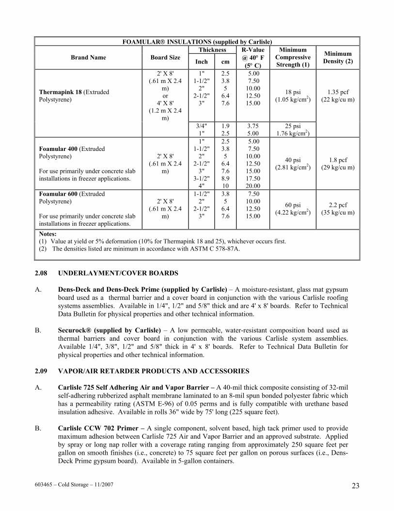
FOAMULAR INSULATIONS (supplied by Carlisle) Thickness
Brand Name Board Size Inch cm
R-Value @ 40° F (5° C)
Minimum Compressive Strength (1)
Minimum Density (2)
Thermapink 18 (Extruded Polystyrene)
2' X 8' (.61 m X 2.4
m) or
4' X 8' (1.2 m X 2.4
m)
1" 1-1/2"
2" 2-1/2"
3"
2.5 3.8 5
6.4 7.6
5.00 7.50 10.00 12.50 15.00
18 psi (1.05 kg/cm2)
1.35 pcf (22 kg/cu m)
3/4" 1"
1.9 2.5
3.75 5.00
25 psi 1.76 kg/cm2)
Foamular 400 (Extruded Polystyrene) For use primarily under concrete slab installations in freezer applications.
2' X 8' (.61 m X 2.4
m)
1" 1-1/2"
2" 2-1/2"
3" 3-1/2"
4"
2.5 3.8 5
6.4 7.6 8.9 10
5.00 7.50 10.00 12.50 15.00 17.50 20.00
40 psi (2.81 kg/cm2)
1.8 pcf (29 kg/cu m)
Foamular 600 (Extruded Polystyrene) For use primarily under concrete slab installations in freezer applications.
2' X 8' (.61 m X 2.4
m)
1-1/2" 2"
2-1/2" 3"
3.8 5
6.4 7.6
7.50 10.00 12.50 15.00
60 psi (4.22 kg/cm2)
2.2 pcf (35 kg/cu m)
Notes: (1) Value at yield or 5% deformation (10% for Thermapink 18 and 25), whichever occurs first. (2) The densities listed are minimum in accordance with ASTM C 578-87A.
2.08 UNDERLAYMENT/COVER BOARDS A. Dens-Deck and Dens-Deck Prime (supplied by Carlisle) – A moisture-resistant, glass mat gypsum
board used as a thermal barrier and a cover board in conjunction with the various Carlisle roofing systems assemblies. Available in 1/4", 1/2" and 5/8" thick and are 4' x 8' boards. Refer to Technical Data Bulletin for physical properties and other technical information.
B. Securock® (supplied by Carlisle) – A low permeable, water-resistant composition board used as
thermal barriers and cover board in conjunction with the various Carlisle system assemblies. Available 1/4", 3/8", 1/2" and 5/8" thick in 4' x 8' boards. Refer to Technical Data Bulletin for physical properties and other technical information.
2.09 VAPOR/AIR RETARDER PRODUCTS AND ACCESSORIES A. Carlisle 725 Self Adhering Air and Vapor Barrier – A 40-mil thick composite consisting of 32-mil
self-adhering rubberized asphalt membrane laminated to an 8-mil spun bonded polyester fabric which has a permeability rating (ASTM E-96) of 0.05 perms and is fully compatible with urethane based insulation adhesive. Available in rolls 36" wide by 75' long (225 square feet).
B. Carlisle CCW 702 Primer – A single component, solvent based, high tack primer used to provide
maximum adhesion between Carlisle 725 Air and Vapor Barrier and an approved substrate. Applied by spray or long nap roller with a coverage rating ranging from approximately 250 square feet per gallon on smooth finishes (i.e., concrete) to 75 square feet per gallon on porous surfaces (i.e., Dens-Deck Prime gypsum board). Available in 5-gallon containers.
603465 – Cold Storage – 11/2007 23

C. Carlisle CCW Blackline 400 – A 15-mil thick, high performance, below slab reinforced vapor barrier. Available size is 13' wide and 82' long. This product has a perm rating of 0.012 in accordance with ASTM E-96 test method. Install loose laid and continuously seal joints and junctions with CCW TGM 3300, butyl-based adhesive sealant.
D. Carlisle Elephant Skin Geomembrane – An 8-mil thick, single layer, virgin low-density
polyethylene vapor and air barrier for below-grade damproofing applications. This membrane is suitable for areas that are sensitive to humidity. Available in 6-1/2' and 13' widths and a 164' length.
E. Water Cut-Off Mastic – Used as a mastic to prevent moisture vapor migration at junctures where
vapor seals are required. This product can also be used for compression terminations and beneath conventional metal edging (at a coverage rate of approximately 10' per tube or 100' per gallon).
F. TGM 3300 – A butyl-based, adhesive sealant used for seaming applications in conjunction with the
Carlisle Elephant Skin Geomembrane and Carlisle CCW Blackline 400. This product can also be used to prevent moisture vapor migration where shown on applicable Carlisle Cold Storage details. Available in rolls 2" and 4" wide and 50' lengths.
2.10 EDGINGS AND TERMINATIONS Products listed below can be used with any of the available Carlisle Roofing Systems. Refer to the applicable Carlisle details and installation instruction manuals for specific installation criteria. A. SecurEdge™ 200 – A snap-on edge system consisting of 24 gauge galvanized metal water dam and
40, 50 or 63-mil thick Kynar 500, clear and colored anodized finish or 24-gauge steel, Kynar 500 finish. The fascia is available in a variety of colors and heights varying from 5" to 12-1/2". Custom fascias and colors are available upon request.
B. SecurEdge 1000 – A metal anchor bar fascia system consisting of a formed quarter hard 0.050"
aluminum retainer bar, corrosion resistant fasteners and a 0.040" aluminum or 24 gauge steel snap-on fascia cover. Available in two versions, one for Fully Adhered and Mechanically-Fastened Roofing Systems and one for Ballasted Roofing Systems.
C. SecurEdge 2000 – An anchor bar roof edge fascia system consisting of heavy .100" thick extruded
aluminum bar, corrosion resistant stainless steel fasteners and snap-on fascia cover used with Adhered, Mechanically Fastened and Ballasted assemblies. Refer to installation instructions for various sizes, colors and accessories.
D. SecurEdge 3000 – A metal anchor bar fascia system consisting of a 20 gauge steel retainer bar,
corrosion resistant fasteners and an aluminum or 24 gauge steel snap-on fascia cover. It is for use in Fully Adhered and Mechanically-Fastened Roofing Systems only.
E. Sure-Seal Drip Edge – Designed for use on Adhered and Mechanically-Fastened Roofing Systems.
Includes a 22 gauge continuous 12' pre-punched 90-degree angle cleat and 12' long fascia sections. Incorporates concealed joint covers and strong 1-1/4" ring shank nails to provide long-term holding power. A selection of colors in 24 gauge steel, Kynar® 500 and 32-mil aluminum finish or Kynar 500 is available.
F. SecurEdge 1 Piece Gravel Stop – Designed for use on Adhered, Mechanically Fastened and
Ballasted Roofing Systems. Includes a 22 gauge continuous 12' pre-punched 90-degree angle cleat and 12' long fascia sections. Incorporates concealed joint covers and strong 1-1/4" ring shank nails to provide long-term holding power. A selection of colors in 40, 50 or 63-mil thick Kynar 500, clear and colored anodized finish or 24 gauge steel, Kynar 500 finish. The fascia is available in a variety of colors and heights are custom fabricated to meet specific project requirements.
603465 – Cold Storage – 11/2007 24

G. SecurEdge Coping – Incorporates an anchor cleat with pre-slotted holes, a concealed joint cover and 10’or 12' continuous sections of coping cap consisting of 40, 50, 63 or 80-mil thick Kynar 500, clear and colored anodized finish or 24 gauge steel, Kynar 500 finish. The coping cap is available in a variety of colors and widths. Custom pieces such as tees, crosses, radius copings, etc., are also available.
H. Sure-Weld Coated Metal (for TPO membrane installations only) – A 24-gauge, galvanized steel
sheet coated with a layer of non-reinforced Sure-Weld Flashing. The sheet is cut to the appropriate width and used to fabricate metal drip edges or other roof perimeter edging profiles. Sure-Weld Membrane may be heat welded directly to the coated metal. Coated metal is available in sheets 4' X 10' and comes packaged 25 sheets per pallet (also available packaged 10 sheets per pallet on a direct ship basis). Available in white, gray or tan.
I. Sure-Seal Ballast Retaining Bar – A ballast retaining perimeter securement system comprised of a
slotted (4" on center) extruded mil aluminum retention bar with an integrated compression fastening strip. 1-1/2" stainless steel fasteners with Neoprene washers are provided for stable securement.
J. Termination Bar – A 1" wide and 98-mil thick extruded aluminum bar pre-punched 6" on center
which incorporates a sealant ledge to support Lap Sealant and provide increased stability for membrane terminations.
2.11 OTHER CARLISLE ACCESSORIES A. Protective Mat – A nominal 6-ounce per square yard, black, UV resistant, polypropylene fabric for use
as an underlayment for crushed stone or pavers and a puncture protection mat for various Carlisle Roofing Systems. Available in rolls 15' wide by 300' long.
B. HP Splice Wipes – Used in conjunction with Splice Cleaners or HP-250 Primer to clean membrane prior
to splicing or applying Lap Sealant. C. Hycron Gloves – A specially coated glove for protection of hands from irritations and stains during the
use of Splice Cleaners, Primers, Splicing Cements and Bonding Adhesives. D. Expansion Joint Supports – A high quality foamed EPDM expansion joint support for use with all Sure-
Seal/Sure-White Roofing Systems; available in two profiles for use at expansion joints within the field of the roof and along parapet walls.
E. Pressure-Sensitive Walkway Pads – A black, molded walkway pads with Factory-Applied SecurTAPE
used to provide protection for areas of EPDM membrane that are exposed to regular rooftop maintenance. F. Sure-Weld Heat Weldable Walkway Rolls – Consists of recycled Sure-Weld Membrane offering
superior tear, puncture and weather resistance and designed to protect Sure-Weld membrane in those areas exposed to repetitive foot traffic or other hazards. Walkway material may be heat welded to Sure-Weld membrane using an automated heat welder or hand held heat welder. Walkway Rolls are 30" wide by 50' long and are nominal 120 mils thick. Available in white only.
G. Walkway Rolls – A black, shredded, compressed rubber walkway pad available in 30" wide by 30' long
rolls, approximately 5/16" in thickness. H. Sure-Seal Rubber Pavers – A 2' by 2' by 2" thick rubber paver weighing approximately 24 pounds per
unit, 6 pounds per square foot manufactured from recycled rubber, which provides a resilient, shock absorbing, weather resistant surface. Designed for use as a walkway offering a unique, environmentally sound advantage over concrete pavers. Features include freeze/thaw stability, bi-directional drainage and no breakage concerns. Available in black and terra cotta.
603465 – Cold Storage – 11/2007 25

I. Olympic Pipe Support System – A non-penetrating support system designed to carry piping, conduit, ductwork and elevated walkways across the roof or to support equipment such as air conditioners on the roof.
PART III EXECUTION 3.01 GENERAL A. Coordinate work with other trades to reduce the possibility of damage to partially completed roof sections
or the below slab thermal protection system caused by construction traffic. B. Do not proceed with installation of below slab components until the mud slab has fully cured and is
suitable for placement of the vapor barrier and other insulating material. C. Prior to commencement of the work, ensure transition details (vapor seal to insulated wall panel) can
perform adequately. If necessary, a prototype should be constructed to demonstrate proper application procedures.
D. When possible on multiple level roofs, begin the work on the highest level to avoid or minimize
construction traffic on completed roof sections. E. On projects at high altitudes (6,000' and above), rapid flash off (drying) of Bonding Adhesive and
Splicing Cement will occur due to low atmospheric pressure. 3.02 ROOF DECK CRITERIA A. Proper decking shall be provided by the building owner. The building owner or its designated
representative must ensure that the building structure is investigated by a registered engineer to assure its ability to withstand the total weight of the specified roofing system, as well as construction loads and live loads, in accordance with all applicable codes. The specifier must also designate the maximum allowable weight and location for material loading and storage on the roof.
B. Withdrawal resistance tests are strongly suggested to determine the suitability of a roof deck. For
questionable pullouts refer to the applicable Adhered or Mechanically Fastened Roofing System specification.
C. Acceptable roof decks are structural concrete (3000 psi or greater), 1" thick wood plank or 15/32" thick
CDX plywood, or steel (22 gauge or heavier). Steel decks of lesser gauge require pullouts to be evaluated and a heavier fastening density may be required.
D. On reroofing projects, core cuts should be taken and the roof must be investigated to determine if the
existing components could remain and to verify the roof deck is structurally suitable to receive the roofing system.
E. Refer to Carlisle published specifications for other roof deck requirements dictated by the type of roof
assembly to be installed.
603465 – Cold Storage – 11/2007 26

3.03 SUBSTRATE PREPARATION Defects in the substrate surface must be reported and documented to the specifier, general contractor and building owner for assessment. The Carlisle Authorized Roofing Applicator shall not proceed with installation unless defects are corrected. A. On retrofit - recover projects, cut and remove wet insulation, as identified by the specifier, and fill all
voids with new insulation so it is relatively flush (+/- 1/4") with the existing surface.
1. When installing this roofing system over an existing gravel surfaced built-up roof, loose gravel must be removed. Power brooming is recommended by Carlisle to remove the loose gravel, which may trap moisture. Any uneven areas of the substrate must be leveled to prevent insulation from bridging.
2. When installing this roofing system over an existing smooth surfaced modified bitumen, EPDM
membrane shall be positioned with the length of sheets parallel to modified bitumen field splices. At end laps or other locations where EPDM splices intersect modified bitumen field seams, Pressure-Sensitive "T" Joint Covers or 6" wide Pressure-Sensitive Uncured Elastoform Flashing must be applied over intersections.
B. For all projects (new or retrofit), the substrate must be relatively even without noticeable high spots or
depressions. Accumulated water, ice or snow must be removed to prevent the absorption of moisture in the new roofing components and roofing system.
C. Prior to placement of new insulation:
1. Clear the substrate of debris and foreign material that may be harmful to the roofing system. Fill any gaps in the substrate with high-rise foam to ensure an airtight seal.
2. All boards shall be tightly butted together. Stop insulation approximately 1/2" away from walls
and penetrations to allow for adequate application of expandable foam.
3. Where the steel deck flutes are perpendicular to the perimeter wall, fill the flutes 12" away from the wall with spray foam insulation.
3.04 VAPOR BARRIER/VAPOR SEAL INSTALLATION The primary concern in the design of a low-temperature facility is the vapor retarder system, which should be as close to 100% effective as is practical. The success or failure of an insulation envelope is due entirely to the effectiveness of the vapor retarder system in preventing water vapor transmission into and through the insulation. A. Below Slab Vapor Barrier
1. Ensure the cured mud slab is smooth, free of fins, sharp objects and foreign materials. Loose lay the Blackline 400 Vapor Barrier over the mud slab overlapping adjoining sheets 1" to 2". Seal the overlaps with TGM 3300.
2. To form a vapor seal transition, install Pressure-Sensitive Cured Curb Flashing forming a seal
against the vapor barrier. Protect flashing from damage until insulated wall panels are ready for installation. Apply a generous amount of Water Cut-Off Mastic beneath the flashing (against the foundation wall) and above the flashing directly below the sill angle.
3. Turn curb flashing up against the insulated wall panel and apply generous beads of Water Cut-Off
Mastic to ensure a continuous seal once the metal trim is installed. Fastening of metal trim shall not exceed 6" on center.
603465 – Cold Storage – 11/2007 27

4. Install multiple layers of EPS insulation loosely laid above the vapor barrier and cover insulation with a slip-sheet of CCW Elephant Skin. Adjoining rolls of slip-sheet shall be overlapped and taped with TGM 3300.
5. Temporarily protect the slip-sheet and the sub-slab insulation assembly by pacing temporary
weights until the concrete floor is ready to be poured. B. Roofing Vapor Barrier
In cold storage and freezer facilities the moisture drive is generally downward where the roofing membrane serves as a vapor barrier. 1. A vapor retarder may be used in a roofing assembly experiencing severe upward moisture drive
during construction phase. In these assemblies effort must be made to reduce the migration of moisture through ventilation, or by providing longer periods for proper dehydration of concrete floors without the use of propane heaters.
2. If a vapor retarder is specified to safeguard against construction generated moisture, CCW
Blackline 400 or CCW Elephant Skin Vapor Barrier may be used. Follow installation criteria outlined in Paragraph 3.04.A.
C. Vapor Seal Transition at Roof Deck
A continuous vapor seal is essential around roof edges, parapets, roof-to-wall transitions, and directly above interior dividers/partitions separating between cold and warmer controlled environments.
1. Where applicable, ensure the insulated wall panel cap is set in Water Cut-Off Mastic and secured
to the wall panel at 6" on center maximum. 2. Fill panel lows with trowel grade polyurethane sealant to achieve a level, smooth surface
approximately 4" to 6" from the top of the panel.
3. Secure cured membrane flashing through the area of the panel that was leveled using generous application of Water Cut-Off Mastic and the Sure-Seal Termination Bar fastened to achieve constant compression against the panel.
4. The transition vapor seal can be completed by turning the cured flashing over the roofing
membrane setting each layer in generous beads of Water Cut-Off Mastic as outlined in the applicable Carlisle detail.
5. Refer to applicable Cold Storage (CS) Details for alternative methods by which a vapor seal can
be achieved. D. Exterior Wall Panel Corner Flashing
Pressure-Sensitive uncured Elastoform Flashing is used in conjunction with HP-250 Primer to provide a vapor seal at the corners of the insulated wall panel system beneath the exterior metal trim.
603465 – Cold Storage – 11/2007 28

3.05 INSTALLATION OF WOOD NAILERS A. Install wood nailers where required for edging, coping, etc. B. For minimum requirements, follow the Factory Mutual Loss Prevention Data Bulletin 1-49 and ensure an
uninterrupted vapor seal where required. 3.06 INSULATION INSTALLATION A. Acceptable Insulation In addition to insulations identified in individual roofing system specifications, the products listed below offer more economical options suited for multi-layer applications commonly associated with refrigerated assemblies.
1. Adhered Roofing Systems – The membrane may be adhered directly to Carlisle Polyisocyanurate HP-H or Polyisocyanurate DWD.
Direct application over Polyisocyanurate DWD can provide greater uplift resistance eliminating the need for insulation overlayment of DensDeck or HP Recovery Board. Note: Refer to the Carlisle Code Approval Guide for fire rated assemblies using
Polyisocyanurate DWD over wood decks. 2. Ballasted Roofing Systems – The membrane may be installed over Carlisle Polyisocyanurate
HP-H or EPS.
3. Mechanically Fastened Roofing Systems
a. In addition to Sure-Seal Polyisocyanurate, white TPO membrane can be installed directly over Carlisle Insulfoam EPS SP (with SecurPly facer).
b. In addition to Sure-Seal Polyisocyanurate, if the use of expanded polystyrene (unfaced) is
specified, the insulation must be overlaid with HP Recovery Board or DensDeck.
Note: In projects where Factory Mutual (FM) compliance is required, a thermal barrier (gypsum board) will be required under EPS insulation.
B. Insulation Thermal Efficiency
1. The R-value of insulation required varies with the temperature held in the refrigerated space and the conditions surrounding the room.
2. The thermal efficiency for refrigerated facilities of the same capacity vary widely. Many factors,
including building design, indoor and outdoor temperatures, and especially the type and flow of goods expected and the daily freezing capacity, contribute to the refrigeration load.
3. Heat infiltration load varies greatly with the size of the refrigerated area, number of openings to
warm areas, protection on openings, traffic through openings, and cold and warm air temperatures and humidities. Calculation should be based on experience, especially when most of the refrigeration load occurs during daytime operations.
4. The following table shows recommended R-values for different types of facilities. The range in
R-values is due to variations in energy cost, insulation materials, and climatic conditions. For more exact values, consult a designer and/or insulation supplier. The required R-value shall be determined by the designer but shall not be less than that shown.
603465 – Cold Storage – 11/2007 29

Recommended Insulation R-Values
Thermal Resistance R, °F × ft2 × h/Btu Type of Facility
Temperature Range, °F Floors Walls Roofs
Coolers1 40 to 60 10 (Perimeter insulation only) 24 to 30 30 to 36
Receiving/Shipping & Coolers 35 to 45 10 (Perimeter
insulation only) 24 to 33 33 to 39
Chill Coolers1 25 to 35 25 to 30 25 to 30 36 to 42
Holding Freezer 0 to -20 34 to 40 42 to 48 42 to 48
Blast Freezers2 -20 to -40 34 to 40 48 to 52 48 to 51
Blast Freezers2 -40 to -50 34 to 40 48 to 52 54 to 60 Note: Because of the wide range in the cost of energy and the cost of insulation materials based on thermal performance, a recommended R-value is given as a guide in each of the respective areas of construction. For more exact values, consult a designer and/or insulation supplier. 1 If a cooler has the possibility of being converted to a freezer in the future, the owner should consider insulating the facility with the higher R-values from the freezer section. 2 R-values shown are for a blast freezer built within an unconditioned space.
C. Insulation Placement and Attachment
1. Regardless of the roofing assembly, insulation shall be installed in multiple layers with staggered joints. All boards shall be tightly butted together. Stop insulation approximately 1/2" away from walls and penetrations to allow for adequate application of expandable foam.
Efforts shall be made so the top layer of insulation is at least 2" thick in order to reduce the number of fasteners without jeopardizing the performance of the roofing assembly.
2. Where the steel deck flutes are perpendicular to the perimeter wall, fill the flutes 12" away from
the wall with spray foam insulation. 3. For Ballasted Roofing Systems, the insulation may be loose laid in accordance with the published
Carlisle specification. If securement is needed, use either FAST Adhesive or beads of adhesive; mechanical fastening of insulation is not permitted.
4. Adhered Roofing Systems
a. Mechanically fasten insulation at the corners and perimeter with 1 fastener and plate per
every 2 square feet of roof area. Insulation in the field of the roof shall be fastened with 1 fastener and plate per every 4 square feet of roof area.
Notes: A lesser fastening density may be approved depending on specific project
conditions.
FM insured projects require compliance with FM 1-29. Consult local FM office for required fastening enhancements.
b. To reduce thermal bridging, a full spray of FAST Adhesive may be used to attach
individual insulation layers or adhere the top layer to a mechanically fastened bottom layer.
603465 – Cold Storage – 11/2007 30

c. As an option to the full spray, beads of adhesive shall be spaced 4" o.c. at the corners of the roof, 6" o.c. at the perimeter of the roof, and 12" o.c. over the field of the roof.
5. Mechanically Fastened Roofing Systems
Mechanically fasten insulation with 1 fastener and plate per every 4 square feet of roof area.
6. Refer to Part II for applicable products and fastening components for proper securement of insulation.
Note: The width of the roof perimeters and corners shall be 0.4 times the building height or 0.1 times
the building’s lesser plan dimension, whichever is smaller. 3.07 MEMBRANE PLACEMENT AND ATTACHMENT A. General
Position membrane without stretching and allow to relax approximately 30 minutes prior to securement at angle change where applicable or attachment to the substrate.
1. Adhered Roofing Systems – refer to the individual Adhered Roofing System specification
(Design “A” EPDM or TPO, SAT TPO, or FleeceBACK) for applicable installation procedures and enhancements required for extended wind speed coverage.
2. Ballasted Roofing Systems – the membrane shall be loose laid and installed with acceptable
ballast (stone or concrete pavers) in accordance with the American National Standards Institute, ANSI/SPRI RP-4 – 2002 (current edition) Wind Design Guide for Ballasted Single-Ply Roofing Systems.
3. Mechanically Fastened Roofing Systems – refer to the individual Mechanically Fastened
Roofing System specification (EPDM and TPO) for applicable installation procedures and enhancements required for extended wind speed coverage.
B. Details and installation procedures for any of the assemblies mentioned in this specification can be found
in the Carlisle Application specification categorized by roofing system type. 3.08 FLASHING A. To ensure a continuous vapor seal and reduce or eliminate condensation, all roof penetrations through the
refrigerated facility (coolers/freezers) must be insulated in accordance with ASHRAE Refrigeration Handbook, chapter 13.
B. For specific flashing details, the Carlisle CS (Cold Storage) Details can be referenced. Step-by-step
flashing procedures are also outlined in the applicable Carlisle roofing system specification and included with the Carlisle Universal Details.
C. Project details may be submitted to Carlisle for review to clarify flashing methods and products used prior
to installation.
603465 – Cold Storage – 11/2007 31

603465 – Cold Storage – 11/2007 32
Copyright 2007 Carlisle SynTec Incorporated
Carlisle, Sure-Seal, Sure-White, SecurEdge, SecurTAPE, FleeceBACK, Sure-Weld, SAT, FAST, Elastoform, RUSS, Sure-Tough, Pre-KLEENED, and In-Seam Sealant are Trademarks of Carlisle SynTec Incorporated
Hycron is a Trademark of Becton-Dickinson and Company Foamular is a Trademark of Owens Corning
Insulfoam is a Trademark of Premier Industries, Inc. Securock is a Trademark of United States Gypsum Company
Kynar is a Registered Trademark of Atrochem – North America, Inc.
Carlisle SynTec Incorporated P. O. Box 7000
Carlisle, PA 17013-0925 800-479-6832
http://www.carlisle-syntec.com
This specification represents the applicable information available at the time of its publication. Owners, specifiers and Carlisle authorized roofing applicators should consult Carlisle or their Carlisle Manufacturer's Representative for any information that has subsequently been made available. Review the appropriate Carlisle warranty for specific warranty coverage, terms, conditions and limitations.