Embed Size (px)
Citation preview
JURUTERA, November 200630
F E AT U R E
1.0 INTRODUCTIONCold in-place recycling (CIPR) is definedas a pavement rehabilitation technique inwhich the existing pavement materialsare reused in-place as base layer. Thematerials are mixed in-place without theapplication of heat. Stabilising agentssuch as cement, lime, bitumen emulsionor foamed bitumen are added and mixedwith the materials to provide additionalstrength to the pavement. The recycledmaterial is then compacted and awearing course is laid on top of thecompleted base course to provide asmooth riding surface.
CIPR can be used to eliminate avariety of pavement distresses such asrutting, cracking, surface irre g u l a r i t i e sand base problems. The process can becarried out with a single machine or anequipment train consisting of differentmachines. CIPR is an alternative methodto the more traditional methods ofs t ructural overlay or re c o n s t ru c t i o n ,w h e reby existing pavement distre s s e sare addressed and additional strengthre q u i red for future traffic increase isprovided for, by using a stabilising agentto increase the load carrying properties ofthe recycled pavement base.
CIPR can be performed in twoways: in partial-depth recycling, 50-100mm of the asphalt layer is used top roduce a base course. In full depthrecycling, also known as full depthreclamation, both asphalt and portionsof unbound aggregate layers arec rushed, mixed with binder, and placedas a stabilised base course. However,the Asphalt Recycling and ReclaimingAssociation (ARRA) defines cold in-place recycling as partial depthrecycling of the existing pavementwhile the full depth recycling is definedas full depth reclamation [1].
This article attempts to provide abrief introduction to the CIPR pro c e s s ,equipment for the process, selectioncriteria for the suitable pavementcandidate, mix design, constru c t i o np rocess, quality control and finally, the
advantages and disadvantages of thismethod. The construction process to beexplained is confined to the single passequipment train. This article focuses onfull depth reclamation rather thanpartial depth re c y c l i n g .
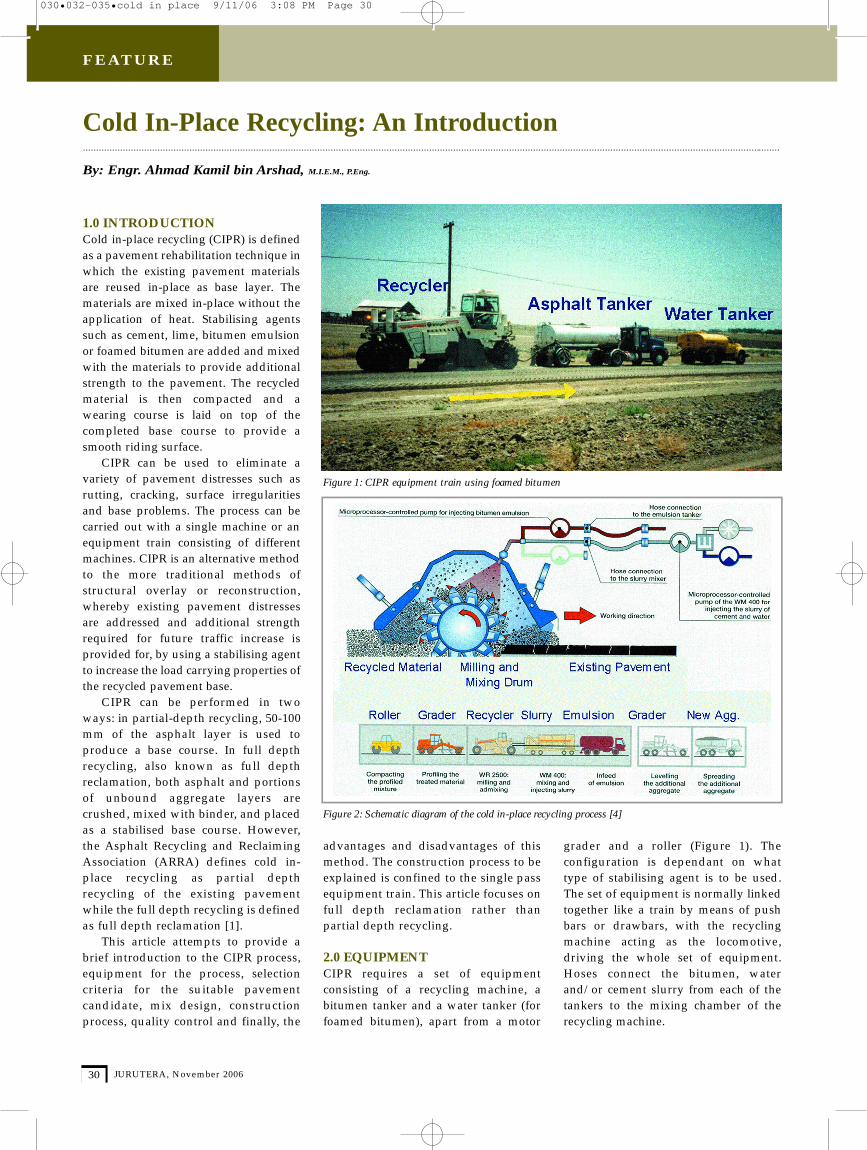
2.0 EQUIPMENTCIPR re q u i res a set of equipmentconsisting of a recycling machine, abitumen tanker and a water tanker (forfoamed bitumen), apart from a motor
grader and a roller (Figure 1). Theconfiguration is dependant on whattype of stabilising agent is to be used.The set of equipment is normally linkedtogether like a train by means of pushbars or drawbars, with the re c y c l i n gmachine acting as the locomotive,driving the whole set of equipment.Hoses connect the bitumen, waterand/or cement slurry from each of thetankers to the mixing chamber of therecycling machine.
Cold In-Place Recycling: An Intr oduction......................................................................................................................................................................................................................................................................
By: Engr. Ahmad Kamil bin Arshad, M.I.E.M., P.Eng.
Figure 1: CIPR equipment train using foamed bitumen
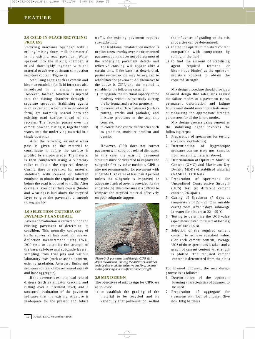
Figure 2: Schematic diagram of the cold in-place recycling process [4]
030•032-035•cold in place 9/11/06 3:08 PM Page 30
JURUTERA, November 200632
F E AT U R E
3.0 COLD IN-PLACE RECYCLINGPROCESSRecycling machines equipped with amilling/mixing drum, mills the materialin the existing road pavement. Water,sprayed into the mixing chamber, ismixed thoroughly together with thematerial to achieve optimum compactionmoisture content (Figure 2).
Stabilising agents such as cement andbitumen emulsion (in fluid form) are alsoi n t roduced in a similar manner.H o w e v e r, foamed bitumen is injectedinto the mixing chamber through aseparate spraybar. Stabilising agentssuch as cement, which are in powderedform, are normally spread onto theexisting road surface ahead of there c y c l e r. The recycler passes over thecement powder, mixing it, together withwater, into the underlying material in asingle operation.
After the recycling, an initial rollerpass is given to the material toconsolidate it before the surface isprofiled by a motor grader. The materialis then compacted using a vibratoryroller to obtain the re q u i red density.Curing time is re q u i red for materialstabilised with cement or bitumenemulsion to obtain the required strengthbefore the road is opened to traffic. Aftercuring, a layer of surface course (binderand wearing) is laid above the recycledlayer to give the pavement a smoothriding quality.
4.0 SELECTION CRITERIA OFPAVEMENT CANDIDATE Pavement evaluation is carried out on theexisting pavement to determine itscondition. This normally comprises oftraffic survey, surface condition survey,deflection measurement using FWD,DCP tests to determine the strength ofthe base, sub-base and subgrade layers ,sampling from trial pits and variouslaboratory tests (such as asphalt content,existing gradation, Atterberg limits andmoisture content of the reclaimed asphaltand base aggregate).
If the pavement exhibits load-relateddistress (such as alligator cracking andrutting over a threshold level) and as t ructural evaluation of the pavementindicates that the existing structure isinadequate for the present and future
traffic, the existing pavement requiresstrengthening.
The traditional rehabilitation method isto place a new overlay over the deterioratedpavement but this does not address most ofthe underlying pavement defects andreflective cracking will appear after acertain time. If the base has deteriorated,partial re c o n s t ruction may be re q u i red torehabilitate the pavement. An alternative tothe above is CIPR and the method issuitable for the following cases [2]:1 ) to upgrade the structural capacity of the
roadway without substantially altering the horizontal and vertical geometry.
2) to correct all surface distresses (such as rutting, cracks and potholes) and mixture problems in the asphaltic c o n c re t e .
3 ) to correct base course deficiencies such as gradation, moisture problem and d e n s i t y.
However, CIPR does not correctpavement with subgrade related distre s s e s .In this case, the existing pavements t ru c t u re must be disturbed to improve thesubgrade first by other methods. CIPR isalso not recommended for pavement withsubgrade CBR value of less than 3 perc e n tunless the subgrade is improved oradequate depth of cover is provided for thesubgrade [6]. This is because it is difficult tocompact the recycled material eff e c t i v e l yon poor subgrade support.
5.0 MIX DESIGN The objectives of mix design for CIPR areas follows:1) to establish the grading of the
material to be recycled and itsvariability after pulverisation, so that
the influences of grading on the mixproperties can be determined;
2) to find the optimum moisture content compatible with compaction byrolling in the field;
3) to find the amount of stabilising agent re q u i red (cement or bituminous binder) at the optimumm o i s t u re content to obtain therequired strength.
Mix design pro c e d u re should provide abalanced design that safeguards againstthe failure modes of a pavement (shear,permanent deformation and fatiguef a i l u re) and should incorporate tests aimedat measuring the appropriate stre n g t hparameters for all the failure modes.
Mix design process using cement asthe stabilising agent involves thefollowing steps:1. Preparation of specimens for testing
(five nos. 7kg batches).2. Determination of hygro s c o p i c
moisture content (two nos. samples from remaining material above).
3. Determination of Optimum MoistureContent (OMC) and Maximum DryDensity MDD) of stabilised material(AASHTO T180 test).
4. P reparation of specimens forUnconfined Compressive Stre n g t h(UCS) Test (at diff e rent cementcontent, 2% apart) .
5. Curing of Specimen (7 days attemperature of 22 – 25 ˚C in suitablecuring room. After 7 days, submergein water for 4 hours at 22 – 25 ˚C.
6. Testing to determine the UCS value(specimens tested to failure at loadingrate of 140 kPa/ s).
7. Selection of the re q u i red cementcontent to achieve specified value.(For each cement content, average UCS of three specimens is taken and a graph of cement content vs. strength is plotted. The re q u i red cementcontent is determined from the plot.)
For foamed bitumen, the mix designprocess is as follows:1. Determination of the optimum
foaming characteristics of bitumen tobe used.
2. P reparation of aggregate fortreatment with foamed bitumen (fivenos. 10kg batches).
F i g u re 3: A pavement candidate for CIPR (fulldepth reclamation) Among the distresses identifiedinclude deep cracking, reflective cracking, pothole,rutting/shoving and insufficient base stre n g t h
030•032-035•cold in place 9/11/06 3:08 PM Page 32
JURUTERA, November 2006 33
F E AT U R E
3. Determination of optimum bindercontent for the prepared aggregates(at diff e rent binder content, 1% apart).• Sample preparation and treatment
with foamed bitumen.• P reparation of Briquettes (using
Marshall mould with 75 hammerblows on each face).
• Curing (24 hours in mould at roomtemperature and 72 hours at 40˚C).
• Calculation of dry density of compacted specimens.
• Determination of Indirect Tensile Strength (ITS) value.
• Determination of Design BitumenContent (bitumen content atmaximum value of soaked ITS).
4. Other material properties such asResilient Modulus and DynamicC reep, if re q u i red, are alsodetermined.
Detailed explanation of the mixdesign process (including mix designusing bitumen emulsion as stabilisingagent) can be found in publications aslisted in the Bibliography section.
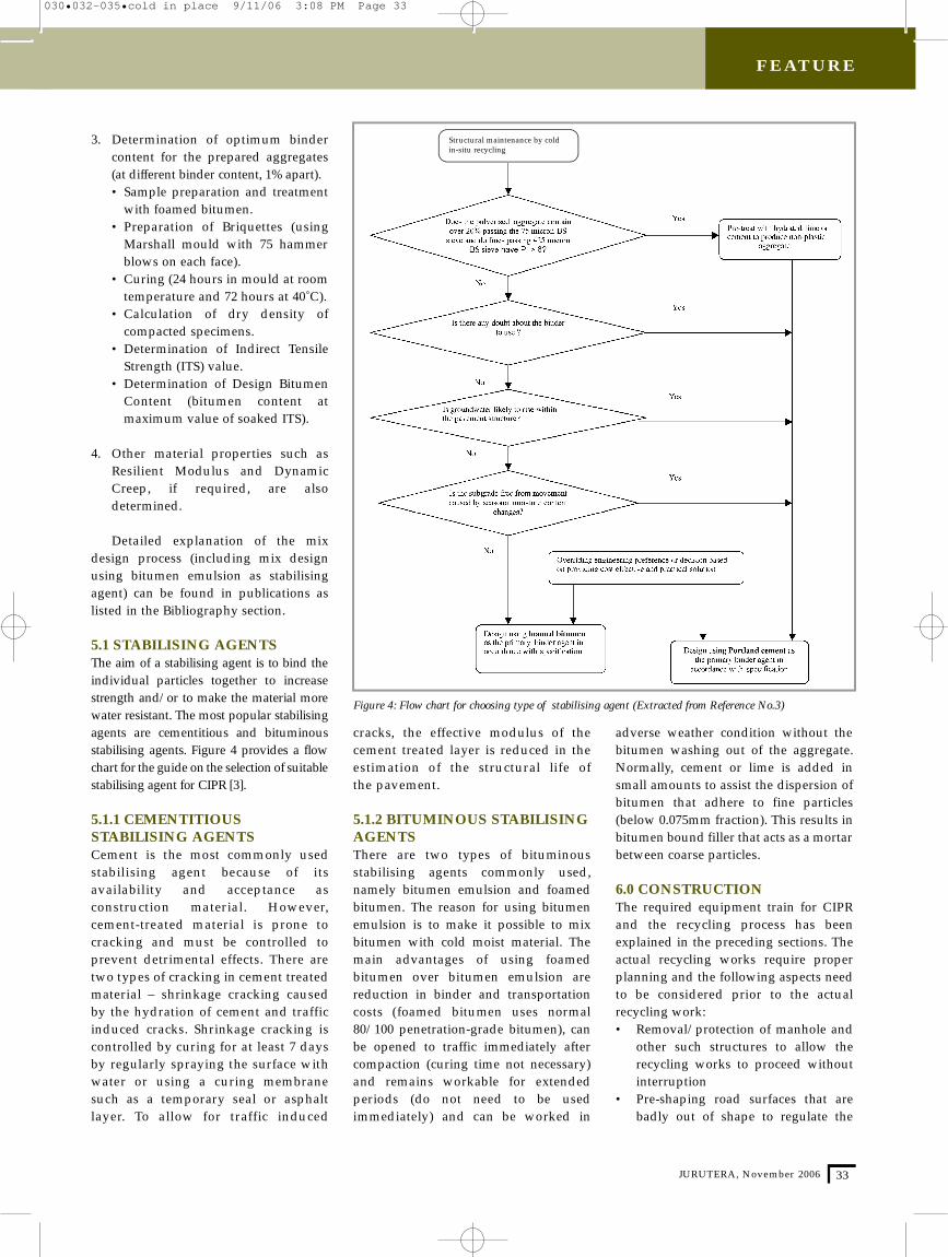
5.1 STABILISING AGENTS The aim of a stabilising agent is to bind theindividual particles together to incre a s es t rength and/or to make the material morewater resistant. The most popular stabilisingagents are cementitious and bituminousstabilising agents. Figure 4 provides a flowchart for the guide on the selection of suitablestabilising agent for CIPR [3].
5.1.1 CEMENTITIOUSSTABILISING AGENTS Cement is the most commonly usedstabilising agent because of itsavailability and acceptance asc o n s t ruction material. However,c e m e n t - t reated material is prone tocracking and must be controlled top revent detrimental effects. There aretwo types of cracking in cement tre a t e dmaterial – shrinkage cracking causedby the hydration of cement and traff i cinduced cracks. Shrinkage cracking isc o n t rolled by curing for at least 7 daysby regularly spraying the surface withwater or using a curing membranesuch as a temporary seal or asphaltl a y e r. To allow for traffic induced
cracks, the effective modulus of thecement treated layer is reduced in theestimation of the structural life of the pavement.
5.1.2 BITUMINOUS STABILISINGAGENTS T h e re are two types of bituminousstabilising agents commonly used,namely bitumen emulsion and foamedbitumen. The reason for using bitumenemulsion is to make it possible to mixbitumen with cold moist material. Themain advantages of using foamedbitumen over bitumen emulsion arereduction in binder and transportationcosts (foamed bitumen uses normal80/100 penetration-grade bitumen), canbe opened to traffic immediately aftercompaction (curing time not necessary)and remains workable for extendedperiods (do not need to be usedimmediately) and can be worked in
adverse weather condition without thebitumen washing out of the aggregate.Normally, cement or lime is added insmall amounts to assist the dispersion ofbitumen that adhere to fine particles(below 0.075mm fraction). This results inbitumen bound filler that acts as a mortarbetween coarse particles.
6.0 CONSTRUCTION The required equipment train for CIPRand the recycling process has beenexplained in the preceding sections. Theactual recycling works re q u i re pro p e rplanning and the following aspects needto be considered prior to the actualrecycling work:• Removal/protection of manhole and
other such structures to allow therecycling works to proceed without interruption
• P re-shaping road surfaces that arebadly out of shape to regulate the
Figure 4: Flow chart for choosing type of stabilising agent (Extracted from Reference No.3)
Structural maintenance by coldin-situ recycling
030•032-035•cold in place 9/11/06 3:08 PM Page 33
JURUTERA, November 200634
F E AT U R E
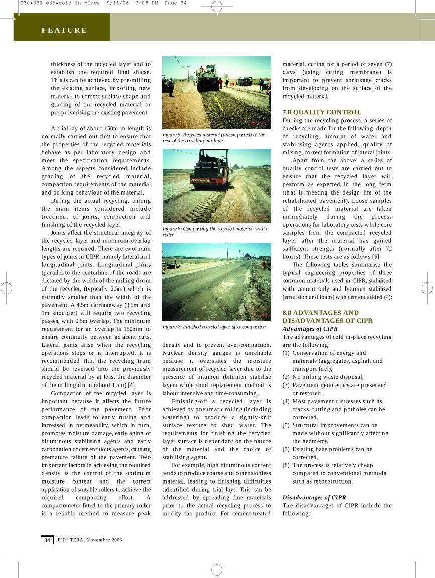
thickness of the recycled layer and toestablish the re q u i red final shape.This is can be achieved by pre-millingthe existing surface, importing newmaterial to correct surface shape andgrading of the recycled material orp re-pulverising the existing pavement.
A trial lay of about 150m in length isnormally carried out first to ensure thatthe properties of the recycled materialsbehave as per laboratory design andmeet the specification re q u i re m e n t s .Among the aspects considered includegrading of the recycled material,compaction requirements of the materialand bulking behaviour of the material.
During the actual recycling, amongthe main items considered includet reatment of joints, compaction andfinishing of the recycled layer.
Joints affect the structural integrity ofthe recycled layer and minimum overlaplengths are re q u i red. There are two maintypes of joints in CIPR, namely lateral andlongitudinal joints. Longitudinal joints(parallel to the centerline of the road) aredictated by the width of the milling dru mof the re c y c l e r, (typically 2.5m) which isnormally smaller than the width of thepavement. A 4.5m carriageway (3.5m and1m shoulder) will re q u i re two re c y c l i n gpasses, with 0.5m overlap. The minimumre q u i rement for an overlap is 150mm toe n s u re continuity between adjacent cuts.Lateral joints arise when the re c y c l i n goperations stops or is interrupted. It isrecommended that the recycling trainshould be reversed into the pre v i o u s l yrecycled material by at least the diameterof the milling drum (about 1.5m) [4].
Compaction of the recycled layer isimportant because it affects the futureperformance of the pavement. Poorcompaction leads to early rutting andi n c reased in permeability, which in turn,p romotes moisture damage, early aging ofbituminous stabilising agents and earlycarbonation of cementitious agents, causingp re m a t u re failure of the pavement. Tw oimportant factors in achieving the re q u i re ddensity is the control of the optimumm o i s t u re content and the corre c tapplication of suitable rollers to achieve there q u i red compacting effort. Acompactometer fitted to the primary ro l l e ris a reliable method to measure peak
density and to prevent over- c o m p a c t i o n .Nuclear density gauges is unre l i a b l ebecause it overstates the moisturem e a s u rement of recycled layer due to thep resence of bitumen (bitumen stabiliselayer) while sand replacement method islabour intensive and time-consuming.
F i n i s h i n g - o ff a recycled layer isachieved by pneumatic rolling (includingwatering) to produce a tightly-knitsurface texture to shed water. Therequirements for finishing the recycledlayer surface is dependant on the natureof the material and the choice ofstabilising agent.
For example, high bituminous contenttends to produce coarse and cohensionlessmaterial, leading to finishing diff i c u l t i e s(identified during trial lay). This can bea d d ressed by spreading fine materialsprior to the actual recycling process tomodify the product. For cement-tre a t e d
material, curing for a period of seven (7)days (using curing membrane) isimportant to prevent shrinkage cracksf rom developing on the surface of therecycled material.
7.0 QUALITY CONTROLDuring the recycling process, a series ofchecks are made for the following: depthof recycling, amount of water andstabilising agents applied, quality ofmixing, correct formation of lateral joints.
Apart from the above, a series ofquality control tests are carried out toe n s u re that the recycled layer willperform as expected in the long term(that is meeting the design life of therehabilitated pavement). Loose samplesof the recycled material are takenimmediately during the pro c e s soperations for laboratory tests while coresamples from the compacted re c y c l e dlayer after the material has gaineds u fficient strength (normally after 72hours). These tests are as follows [5]:
The following tables summarise thetypical engineering properties of thre ecommon materials used in CIPR, stabilisedwith cement only and bitumen stabilised(emulsion and foam) with cement added (4):
8.0 ADVANTAGES ANDDISADVANTAGES OF CIPR Advantages of CIPRThe advantages of cold in-place recyclingare the following: (1) Conservation of energy and
materials (aggregates, asphalt and transport fuel),
(2) No milling waste disposal, (3) Pavement geometrics are preserved
or restored, (4) Most pavement distresses such as
cracks, rutting and potholes can becorrected,
(5) Structural improvements can bemade without significantly affecting the geometry,
(7) Existing base problems can be corrected,
(8) The process is relatively cheap compared to conventional methods such as reconstruction.
Disadvantages of CIPRThe disadvantages of CIPR include thefollowing:
F i g u re 5: Recycled material (uncompacted) at therear of the recycling machine
F i g u re 6: Compacting the recycled material with aro l l e r
F i g u re 7: Finished recycled layer after compaction
030•032-035•cold in place 9/11/06 3:08 PM Page 34
JURUTERA, November 2006 35
F E AT U R E
(1) High acquisition cost of the CIPRequipment,
(2) A dedicated and skilled team of operators/workers is required,
(3) Existing pavement cross-section andproperties must be relativelyhomogenous for the process,
(4) Extra care must be taken where thereare manholes and services at shallowdepth,
(5) Moisture content of recycledmaterials must be controlled,
(6) Wearing course is required on top of
the recycled layer to provide thesmooth riding quality.
9.0 CONCLUSION CIPR is an economical ande n v i ronmentally sound alternative toconventional rehabilitation methods suchas structural overlay or re c o n s t ruction. Itsuse in Malaysia is expected to increase inthe future as more pavementrehabilitation works instead of new ro a d swill be carried out to preserve theintegrity of the pavement stru c t u re and toextend the pavement life. However, anadequate understanding of the CIPRp rocess, its suitability and limitations isessential for the correct pavementcandidate to be chosen, for the works to becarried out successfully and for thepavement to perform satisfactorily. ■
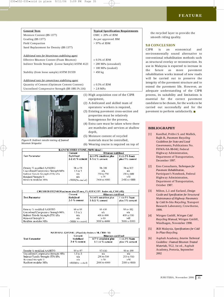
Figure 8: Indirect tensile testing of foamedbitumen briquette
B I B L I O G R A P H Y
[ 1 ] Kandhal, Prithvi S. and Mallick,Rajib B., Pavement RecyclingGuidelines for State and LocalG o v e r n m e n t s, Publications No.F H WA-SA-98-042, FederalHighway A d m i n i s t r a t i o n ,Department of Tr a n s p o r t a t i o n ,December 1997.
[ 2 ] E res Consultants, Techniques forPavement Rehabilitation,Participant’s Notebook, FederalHighway A d m i n i s t r a t i o n ,Department of Tr a n s p o r t a t i o n ,October 1987.
[ 3 ] Milton, L.J. and Earland, D e s i g nGuide and Specification for StructuralMaintenance of Highway Pavementsby Cold In-Situ Recycling, Tr a n s p o r tR e s e a rch Laboratory, Cro w t h o r n e ,1 9 9 9 .
[ 4 ] Wirtgen GmbH, Wirtgen ColdRecycling Manual, Wirtgen GmbH,Windhagen, November 1998.
[ 5 ] JKR Malaysia, Specifications for ColdIn-Place Recycling.
[ 6 ] Asphalt A c a d e m y, Interim Te c h n i c a lGuideline : Foamed Bitumen Tre a t e dM a t e r i a l s, TG2, 1st ed., A s p h a l tA c a d e m y, Pretoria, September2 0 0 2
General Tests Typical Specification Requirements
Moisture Content (BS 1377) OMC ± 20% of JDMGrading (BS 1377) As per approved JSMField Compaction > 97% of JDMSand Replacement for Density (BS 1377)
Additional tests for bituminous stabilising agent
Effective Bitumen Content (Foam Bitumen) ± 0.5% of JDMIndirect Tensile Strength (Loose Sample) ASTM 4123 > 200 MPa (unsoaked)
> 100 MPa (soaked)Stability (from loose sample) ASTM D1559 > 450 kg
Additional tests for cementitous stabilising agent
Quantity of Cement (Optimum Cement Content) ± 0.5% of JDMUnconfined Compressive Strength (BS 1881 Pt.116) > 2.8 MPa
030•032-035•cold in place 9/11/06 3:09 PM Page 35