Embed Size (px)
Citation preview
Coiled-Tubing-Deployed Hard Rock
Thermal Spallation Cavity Maker
Donald Dreesen, Los Alamos National Laboratory Robert Bretz, New Mexico Institute of Mining and Technology
ABSTRACT. A team of Los Alamos National Laboratory and New Mexico Tech engineers, technicians, and students were funded by DOE NETL in September 2002 to demonstrate spallation drilling and cavity formation. Work began in January 2003. This report summarizes the conclusions drawn from the review of previous work and activities and progress made by the team during the first funding increment, Phase I. Plans for the Phase II project are described.
I INTRODUCTION Thermal spallation drilling also called flame-jet drilling (Maurer, 1980) is an effective method of creating holes and cavities in some hard rocks that are expensive to drill using traditional mechanical (rotary and percussion) drilling methods. A hydrocarbon fuel and air are burned in a flame-jet burner to produce a high velocity exhaust that is applied to the rock surface on the bottom of the hole. The rapid heating of the rock creates a large thermal gradient due to rocks inherent low thermal conductivity (Figure 1). The thermal gradient produces high compressive stresses on the surface of the exposed rock and the surface layer buckles wherever rock flaws in the near surface material provide a nucleation point for the creation of free surface (Dey and Kranz, 1987). A more detailed description of the thermal spallation process and a brief history of its application in North America have been described by various authors (Dey and Kranz, 1987; Rauenzahn and Tester, 1985; and Williams et al., 1988).
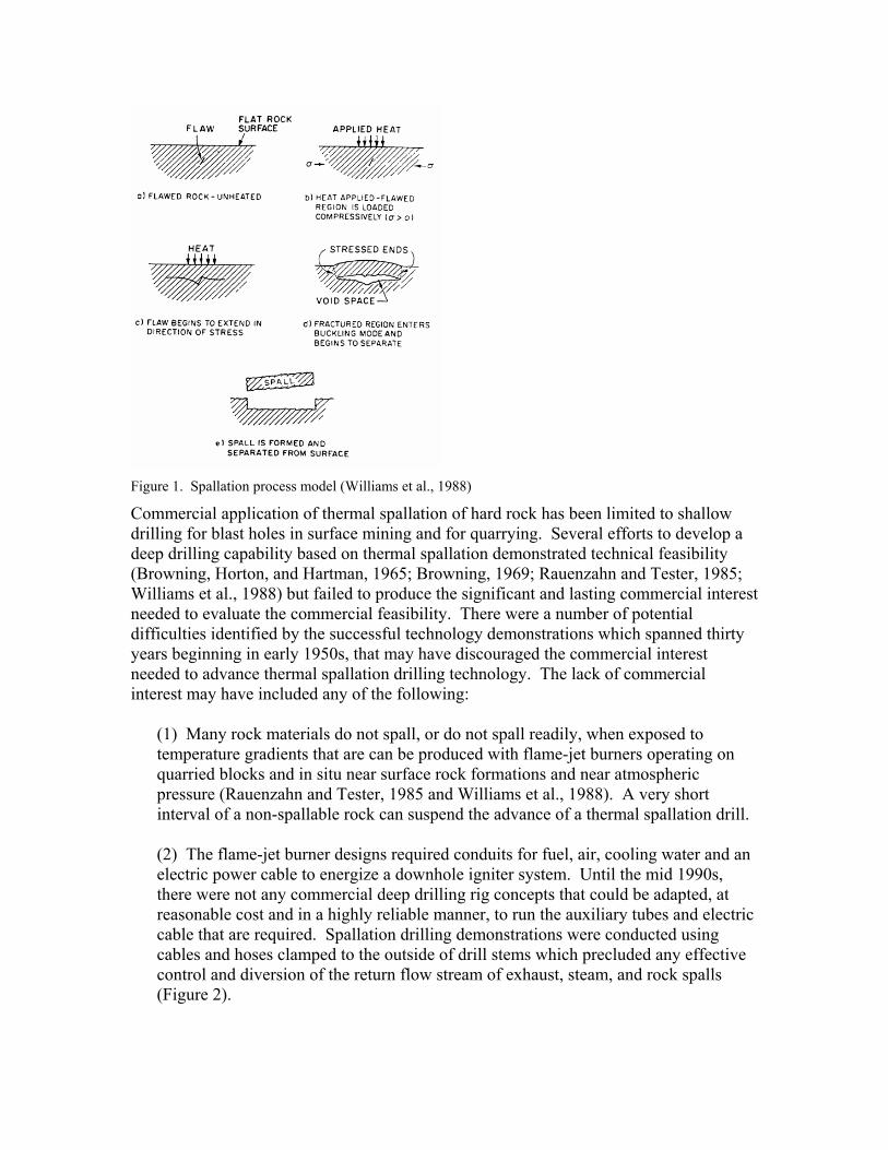
Figure 1. Spallation process model (Williams et al., 1988)
Commercial application of thermal spallation of hard rock has been limited to shallow drilling for blast holes in surface mining and for quarrying. Several efforts to develop a deep drilling capability based on thermal spallation demonstrated technical feasibility (Browning, Horton, and Hartman, 1965; Browning, 1969; Rauenzahn and Tester, 1985; Williams et al., 1988) but failed to produce the significant and lasting commercial interest needed to evaluate the commercial feasibility. There were a number of potential difficulties identified by the successful technology demonstrations which spanned thirty years beginning in early 1950s, that may have discouraged the commercial interest needed to advance thermal spallation drilling technology. The lack of commercial interest may have included any of the following:
(1) Many rock materials do not spall, or do not spall readily, when exposed to temperature gradients that are can be produced with flame-jet burners operating on quarried blocks and in situ near surface rock formations and near atmospheric pressure (Rauenzahn and Tester, 1985 and Williams et al., 1988). A very short interval of a non-spallable rock can suspend the advance of a thermal spallation drill. (2) The flame-jet burner designs required conduits for fuel, air, cooling water and an electric power cable to energize a downhole igniter system. Until the mid 1990s, there were not any commercial deep drilling rig concepts that could be adapted, at reasonable cost and in a highly reliable manner, to run the auxiliary tubes and electric cable that are required. Spallation drilling demonstrations were conducted using cables and hoses clamped to the outside of drill stems which precluded any effective control and diversion of the return flow stream of exhaust, steam, and rock spalls (Figure 2).
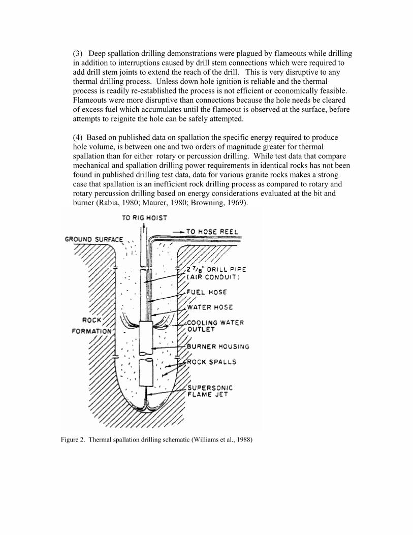
(3) Deep spallation drilling demonstrations were plagued by flameouts while drilling in addition to interruptions caused by drill stem connections which were required to add drill stem joints to extend the reach of the drill. This is very disruptive to any thermal drilling process. Unless down hole ignition is reliable and the thermal process is readily re-established the process is not efficient or economically feasible. Flameouts were more disruptive than connections because the hole needs be cleared of excess fuel which accumulates until the flameout is observed at the surface, before attempts to reignite the hole can be safely attempted. (4) Based on published data on spallation the specific energy required to produce hole volume, is between one and two orders of magnitude greater for thermal spallation than for either rotary or percussion drilling. While test data that compare mechanical and spallation drilling power requirements in identical rocks has not been found in published drilling test data, data for various granite rocks makes a strong case that spallation is an inefficient rock drilling process as compared to rotary and rotary percussion drilling based on energy considerations evaluated at the bit and burner (Rabia, 1980; Maurer, 1980; Browning, 1969).
Figure 2. Thermal spallation drilling schematic (Williams et al., 1988)
II REVIEW OF EARLIER WORK
Theory of Spallation
Dey and Kranz (1985, 1987) formulated a theory of spallation rock failure based on an “uniaxial splitting mechanism” that assumes (1) a steep thermal gradient develops adjacent to the rapidly heated surface, (2) the thermal gradient generates a steep compressive stress gradient normal to the rock surface, (3) fractures form at nucleation points (material heterogeneities, micro fractures, or other flaws) and grow parallel to the rock surface until the stresses and fracture area combine to reach a critical buckling criteria to activate a flat plate buckling mechanism, and (4) buckling then expels the spall from the rock surface. Dey and Kranz applied Weibull statistics to model the probability of fracture initiation based on the distribution of nucleation locations and their free-surface formation potential. From this thermal spallation model, the thermal gradient required to produce a given spallation drilling rate can be estimated and from the gradient the required heat flux and rock surface temperature are derived. Energy Issues
Energy Issues
In Advanced Drilling Techniques, Maurer includes thermal spallation as one of four basic methods for excavating rock. He presents substantial data that shows that mechanical drilling methods are the most efficient way to pulverize rock based on specific energy. Maurer summarizes flame-jet drilling results published by J. A. Browning and others in the 1960s. He also presents other thermal drilling devices including the rocket exhaust drill, a spallation device, and other more exotic drills that remove rock by melting and vaporization but may also support spallation of some rocks under some conditions. Maurer’s review of advanced drilling techniques compares both drilling specific energy –the energy expended to create hole volume, and specific kerfing energy – the energy to create kerf area. Maurer makes the case that effective kerf formation supports the mechanical breakage of the kerfed hole bottom to form very large rock cuttings and results in a very low specific energy process. This holds even when the specific energy of the kerf formation process is high as long as the kerf is very narrow and therefore the kerf volume is low. Flame-jet spallation is not an obvious candidate to produce a narrow kerf. The combination of thermal spallation and mechanical drilling does not appear to produce the synergism that has been achieved with high pressure jets and mechanical drilling. We found no evidence that a combined mechanical-spallation drilling system was ever prototyped and tested. Mechanical and spallation drilling specific energy data for granite are summarized on Table 1. Energy considerations at the bit are a major component of the total cost of excavation, tunneling, and shallow drilling processes but are less significant part of the total cost of deep drilling for a number of reasons. These reasons are: (1) power transport loss between the surface and the bit may be large; (2) the efficiency of the cutting mobilization and removal processes may also be significant part of the total energy (a
synergy between the comminution process and the transport process may be more significant than the energy-at-the-bit consideration), and (3) the cost of the drilling platform and the labor to operate it and required auxiliary systems may be substantially higher than the total energy cost. Therefore drilling cost needs to be evaluated in the context of power requirements as well as cuttings removal in order to properly evaluate and compare various drilling systems. While published data on spallation drilling suggests that flame-jet thermal spallation is not as efficient as mechanical drilling (Table 1), even when the more efficient power transport of chemical energy compared to mechanical and hydraulic transport power is included in the analysis, proponents of spallation drilling make the following arguments: (1) The high cost and short operating life of drill bits used to drill hard crystalline rock has a greater impact on the total drilling cost than the additional energy cost for thermal spallation. (2) In the best candidate rocks for thermal spallation drilling, the penetration rates achieved with spallation drilling will be several or more times greater than those typically achieved with mechanical drilling in deep boreholes. (3) Because the mechanical loading on the bottom of the drill stem is almost negligible with spallation drilling, a substantial reduction in the size of the drilling platform required will more than offset higher energy costs. These arguments all have some merit but it is still important to understand the energy requirements in order to achieve a near optimum design for a deep drilling and cavity formation system. A theoretical lower limit for the specific energy can be readily calculated using either equation (3) in Dey and Kranz (1985, 1987) or by using the estimated Weibull parameters and rock properties from Wilkenson and Tester (1993b). The ratio of these lower theoretical limits to the specific energy values calculated for the Browning et al. (1969) drilling data based on heat of combustion of the fuel air mixtures produces a rough approximation of the total thermal efficiency for thermal spallation. The ratio ranges from 0.090 to 0.125 based on the mechanically derived Wiebull parameters (Dey and Kranz, 1987) and between 0.270 and 0.470 for thermal spallation derived Wiebull parameters estimated by Wilkinson and Tester (1993b). Dey and Kranz (1985) apparently made a similar calculation for the Pedernal drilling experiment (Williams et al., 1988) and concluded that only 15% of the heat energy available is transferred to the rock. Theoretical, bench, and downhole drilling demonstrations provided data that were used to calculate the various spallation drilling specific energy data for granite that are included on Table 1. Table 1. Specific Energy Values for Mechanical and Spallation Drilling Techniques Granite rock type
Specific Energy (J/cm3)
Drilling Technique
Reference
Bench Field Rockville 157 288 Percussion (drifter) Rabia, 1982 Charcoal 193 325 Percussion (drifter) Rabia, 1982
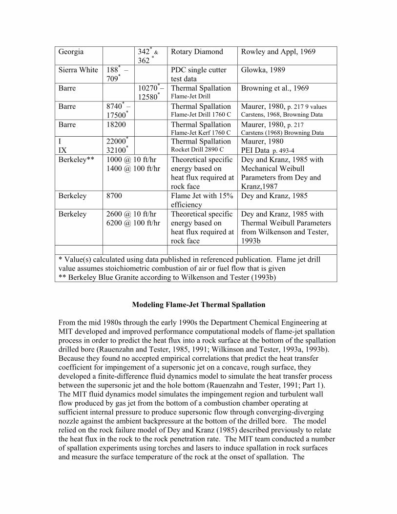
Georgia 342* & 362 *
Rotary Diamond Rowley and Appl, 1969
Sierra White 188* –709*
PDC single cutter test data
Glowka, 1989
Barre 10270*–12580*
Thermal Spallation Flame-Jet Drill
Browning et al., 1969
Barre 8740* – 17500*
Thermal Spallation Flame-Jet Drill 1760 C
Maurer, 1980, p. 217 9 values Carstens, 1968, Browning Data
Barre 18200 Thermal Spallation Flame-Jet Kerf 1760 C
Maurer, 1980, p. 217 Carstens (1968) Browning Data
I IX
22000*
32100* Thermal Spallation
Rocket Drill 2890 C Maurer, 1980 PEI Data p. 493-4
Berkeley**
1000 @ 10 ft/hr 1400 @ 100 ft/hr
Theoretical specific energy based on heat flux required at rock face
Dey and Kranz, 1985 with Mechanical Weibull Parameters from Dey and Kranz,1987
Berkeley 8700 Flame Jet with 15% efficiency
Dey and Kranz, 1985
Berkeley
2600 @ 10 ft/hr 6200 @ 100 ft/hr
Theoretical specific energy based on heat flux required at rock face
Dey and Kranz, 1985 with Thermal Weibull Parameters from Wilkenson and Tester, 1993b
* Value(s) calculated using data published in referenced publication. Flame jet drill value assumes stoichiometric combustion of air or fuel flow that is given ** Berkeley Blue Granite according to Wilkenson and Tester (1993b)
Modeling Flame-Jet Thermal Spallation
From the mid 1980s through the early 1990s the Department Chemical Engineering at MIT developed and improved performance computational models of flame-jet spallation process in order to predict the heat flux into a rock surface at the bottom of the spallation drilled bore (Rauenzahn and Tester, 1985, 1991; Wilkinson and Tester, 1993a, 1993b). Because they found no accepted empirical correlations that predict the heat transfer coefficient for impingement of a supersonic jet on a concave, rough surface, they developed a finite-difference fluid dynamics model to simulate the heat transfer process between the supersonic jet and the hole bottom (Rauenzahn and Tester, 1991; Part 1). The MIT fluid dynamics model simulates the impingement region and turbulent wall flow produced by gas jet from the bottom of a combustion chamber operating at sufficient internal pressure to produce supersonic flow through converging-diverging nozzle against the ambient backpressure at the bottom of the drilled bore. The model relied on the rock failure model of Dey and Kranz (1985) described previously to relate the heat flux in the rock to the rock penetration rate. The MIT team conducted a number of spallation experiments using torches and lasers to induce spallation in rock surfaces and measure the surface temperature of the rock at the onset of spallation. The
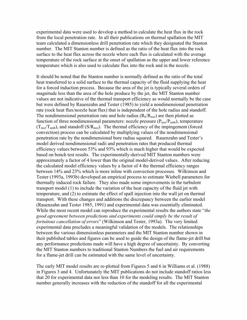
experimental data were used to develop a method to calculate the heat flux in the rock from the local penetration rate. In all their publications on thermal spallation the MIT team calculated a dimensionless drill penetration rate which they designated the Stanton number. The MIT Stanton number is defined as the ratio of the heat flux into the rock surface to the heat flux across the nozzle where each flux is calculated with the average temperature of the rock surface at the onset of spallation as the upper and lower reference temperature which is also used to calculate flux into the rock and in the nozzle. It should be noted that the Stanton number is normally defined as the ratio of the total heat transferred to a solid surface to the thermal capacity of the fluid supplying the heat for a forced induction process. Because the area of the jet is typically several orders of magnitude less than the area of the hole produce by the jet, the MIT Stanton number values are not indicative of the thermal transport efficiency as would normally be the case but were defined by Rauenzahn and Tester (1985) to yield a nondimensional penetration rate (rock heat flux/nozzle heat flux) that is independent of the hole radius and standoff. The nondimensional penetration rate and hole radius (Rh/Rnoz) are then plotted as function of three nondimensional parameters: nozzle pressure (Pnoz/Pamb), temperature (Tnoz/Tamb), and standoff (S/Rnoz). The thermal efficiency of the impingement (forced convection) process can be calculated by multiplying values of the nondimensional penetration rate by the nondimensional bore radius squared. Rauenzahn and Tester’s model derived nondimensional radii and penetration rates that produced thermal efficiency values between 53% and 93% which is much higher that would be expected based on bench test results. The experimentally-derived MIT Stanton numbers were approximately a factor of 4 lower than the original model-derived values. After reducing the calculated model efficiency values by a factor of 4 the thermal efficiency ranges between 14% and 23% which is more inline with convection processes. Wilkinson and Tester (1993a, 1993b) developed an empirical process to estimate Wiebell parameters for thermally induced rock failure. They also made some improvements in the turbulent transport model (1) to include the variation of the heat capacity of the fluid jet with temperature, and (2) to estimate the effect of spall injection into the wall jet on thermal transport. With these changes and additions the discrepancy between the earlier model (Rauenzahn and Tester 1985, 1991) and experimental data was essentially eliminated. While the most recent model can reproduce the experimental results the authors state “the good agreement between predictions and experiments could simply be the result of fortuitous cancellation of errors” (Wilkinson and Tester, 1993a). The very limited experimental data precludes a meaningful validation of the models. The relationships between the various dimensionless parameters and the MIT Stanton number shown in their published tables and figures can be used to guide the design of the flame-jet drill but any performance predictions made will have a high degree of uncertainty. By converting the MIT Stanton numbers to traditional Stanton Numbers the fuel and air requirements for a flame-jet drill can be estimated with the same level of uncertainty. The early MIT model results are re-plotted from Figures 5 and 6 in Williams et al. (1988) in Figures 3 and 4. Unfortunately the MIT publications do not include standoff ratios less that 20 for experimental data nor less than 10 for the modeling results. The MIT Stanton number generally increases with the reduction of the standoff for all the experimental
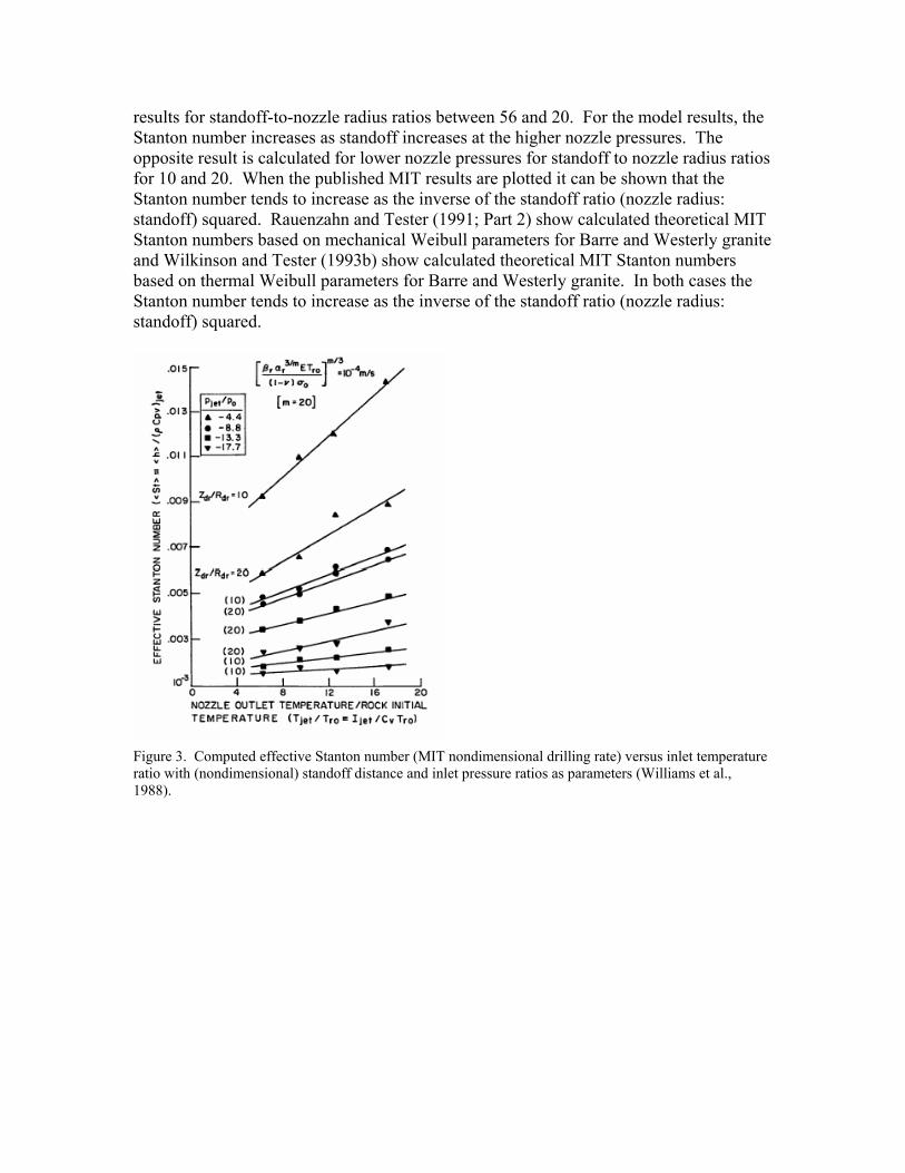
results for standoff-to-nozzle radius ratios between 56 and 20. For the model results, the Stanton number increases as standoff increases at the higher nozzle pressures. The opposite result is calculated for lower nozzle pressures for standoff to nozzle radius ratios for 10 and 20. When the published MIT results are plotted it can be shown that the Stanton number tends to increase as the inverse of the standoff ratio (nozzle radius: standoff) squared. Rauenzahn and Tester (1991; Part 2) show calculated theoretical MIT Stanton numbers based on mechanical Weibull parameters for Barre and Westerly granite and Wilkinson and Tester (1993b) show calculated theoretical MIT Stanton numbers based on thermal Weibull parameters for Barre and Westerly granite. In both cases the Stanton number tends to increase as the inverse of the standoff ratio (nozzle radius: standoff) squared.
Figure 3. Computed effective Stanton number (MIT nondimensional drilling rate) versus inlet temperature ratio with (nondimensional) standoff distance and inlet pressure ratios as parameters (Williams et al., 1988).
Figure 4. Computed dimensionless radius versus inlet temperature ratio with (nondimensional) standoff distance and inlet pressure ratios as parameters (Williams et al., 1988).
Bench Results. Rauenzahn and Tester (1989) used a propane oxygen burner and a 500 W CO2 (10.6 µm) laser to estimate the differential temperature under steady state spallation of Barre and Westerly granite and to evaluate the use of the Weibull theory of rock failure to predict the drilling performance of a flame jet drill. From the analysis of the experimental results they extended the Weibull theory of rock failure, which was developed and verified for the prediction of tensile rock failure, “to allow prediction chip-size distributions and rock surface temperature at spallation under any intense heat source.” They also investigated the use of mechanically determined Weibull parameters to predict thermally induced compressive failures that are the generally accepted model for thermal spallation. They concluded that room temperature measured rock properties and mechanically determined Weibull parameters provide sufficiently accurate prediction of spallation performance for “engineering purposes.” Field Results. Rauenzahn and Tester (1990) found that heat transfer rates derived from actual drilling rates in quarry drilling experiments, unlike bench tests with a propane oxygen touch, were lower than the heat transfer rates predicted in the laboratory tests by at least a factor of four. They concluded that the effects of two phase flow (spalls moving through the flame-jet exhaust boundary layer) and adhesion of the rock particles to the spalling surface needed to be treated rigorously within the model in order to predict drill rates in the field. Wilkinson and Tester (1993b) developed a method to estimate the appropriate Weibull parameters for thermally induced compressive failures during spallation. This change reduced the discrepancy observed by Rauenzahn and Tester to
factor of two. When this is combined with an improved turbulent heat transfer model where the specific heat of the jet fluid is modeled as a function of temperature and the effects of the two phase flow on the turbulent transfer in the boundary layer the discrepancy can be eliminated but the authors admit that the good agreement may be the result of “fortuitous cancellation of errors” and that more experimental and theoretical studies are needed before modeling of the flow field at the spallation surface can be justified.
Deep drilling demonstrations Drilling Performance. Browning (1969) developed an empirical drilling performance chart based on data from downhole drilling, trenching (channeling), and bench drilling and kerfing demonstrations. His chart shows that drilling rate increases with the air pressure delivered to the flame-jet burner and the air supply rate; and drilling rate varies inversely with the hole diameter. Browning, Horton, and Hartman (1965), Browning (1969), and Williams et al. (1988) document a number of observations and measurements made during spallation drilling and cavity forming demonstrations. Williams’ experiment is shown in Figure 5. Important observations applicable to Class II rocks that include granites include:
1. Lower temperature air-fuel flame-jets provide improved performance over that is achieved with higher temperature oxygen-fuel jets.
2. Increasing the jet velocity supports the creation of a small diameter hole. 3. Lower heat flux produces larger diameter holes and vice versa. 4. The highest flame-jet velocity produces the largest thermal gradients, the smallest
spalls, and the highest penetration rates. 5. Lower flame-jet velocity produces the smaller thermal gradients, larger spalls, and
the lower penetration rates. 6. The flame-jet velocity is too low when the low thermal gradients that are
produced relieve the stress in the rock due to softening or melting before stress induced failure of the rock occurs.
7. Oxygen-fuel burners that produce very high thermal gradients may fail to spall across discontinuities of broken rock where an air-fuel burner that produces a lower gradient will spall across the discontinuity with little difficulty.
8. Burners that are capable of producing a large range of flame temperatures and jet velocities should be capable of penetrating more challenging broken rock zones and thin sections of non-spallable rock.
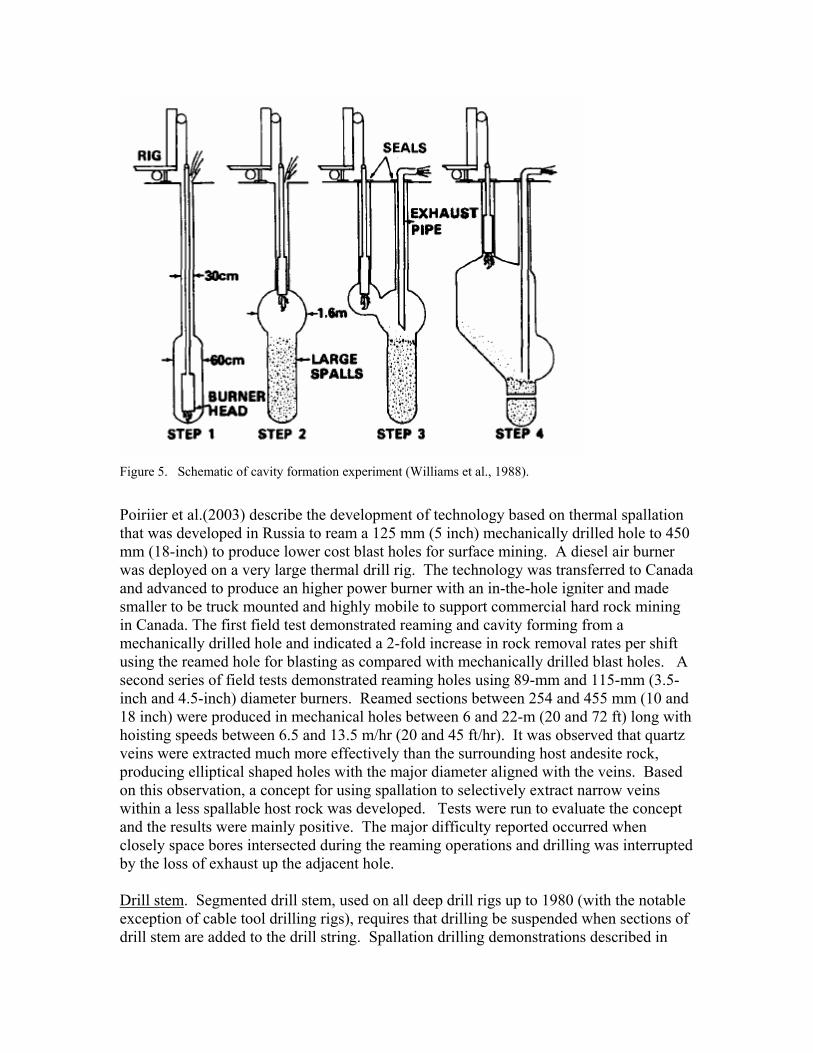
Figure 5. Schematic of cavity formation experiment (Williams et al., 1988).
Poiriier et al.(2003) describe the development of technology based on thermal spallation that was developed in Russia to ream a 125 mm (5 inch) mechanically drilled hole to 450 mm (18-inch) to produce lower cost blast holes for surface mining. A diesel air burner was deployed on a very large thermal drill rig. The technology was transferred to Canada and advanced to produce an higher power burner with an in-the-hole igniter and made smaller to be truck mounted and highly mobile to support commercial hard rock mining in Canada. The first field test demonstrated reaming and cavity forming from a mechanically drilled hole and indicated a 2-fold increase in rock removal rates per shift using the reamed hole for blasting as compared with mechanically drilled blast holes. A second series of field tests demonstrated reaming holes using 89-mm and 115-mm (3.5-inch and 4.5-inch) diameter burners. Reamed sections between 254 and 455 mm (10 and 18 inch) were produced in mechanical holes between 6 and 22-m (20 and 72 ft) long with hoisting speeds between 6.5 and 13.5 m/hr (20 and 45 ft/hr). It was observed that quartz veins were extracted much more effectively than the surrounding host andesite rock, producing elliptical shaped holes with the major diameter aligned with the veins. Based on this observation, a concept for using spallation to selectively extract narrow veins within a less spallable host rock was developed. Tests were run to evaluate the concept and the results were mainly positive. The major difficulty reported occurred when closely space bores intersected during the reaming operations and drilling was interrupted by the loss of exhaust up the adjacent hole. Drill stem. Segmented drill stem, used on all deep drill rigs up to 1980 (with the notable exception of cable tool drilling rigs), requires that drilling be suspended when sections of drill stem are added to the drill string. Spallation drilling demonstrations described in
Browning, Horton, and Hartman (1965), Browning (1969), and Williams et al. (1988) used external hoses and cables, strapped to the drill stem, to supply fuel and water and ignite the burner. Air was supplied down the inside of the drill stem. The spallation drilling process was adversely impacted because the air supply had suspended before and then reestablished after each connection before the burner was reignited. The external appendages are exposed to a potentially severe corrosive erosion environment that precluded the use of traditional surface flow diverters and well control equipment that is required for sealing to the outside of the drill stem. The externals also increased the risk of sticking the drill stem if a hose or cable connection were to separate in the annulus. The auxiliaries were run either inside the drill stem or as an integral part of the drill stem. Internal tubing and cables were totally self supporting. They were removed and reinstalled after each section of drill stem wasadded to the drill string. Various systems to make the auxiliary conduits and cables integral to the drill stem have be fabricated but none of the prototypes found commercial acceptance due to their high costs and low reliability. Coiled tubing drilling. Coiled tubing units use small diameter reeled tubing instead of jointed tubing to circulate fluids and insert and remove equipment for the bottom of deep wells. Coiled tubing achieved commercial acceptance for cleanout and remedial well servicing in oil and gas wells starting in the late 1970s. As the diameter and strength of coiled tubing were both increased during the 1980s it became technically feasible to deploy rotary drilling equipment on downhole hydraulic motors run on coiled tubing units by the early 1990s (Leising and Newman, 1993). Since then coiled-tubing deployed drilling has found a gradual commercial acceptance and the size and strength of coiled tubing has continued to increase to support a wider range of drilling and well servicing applications (Figure 6). By the mid 1990s coiled tubing could be purchased with factory installed internal cables, wirelines, and hydraulic tubing (Precession Tube Technology, Inc., 1999).
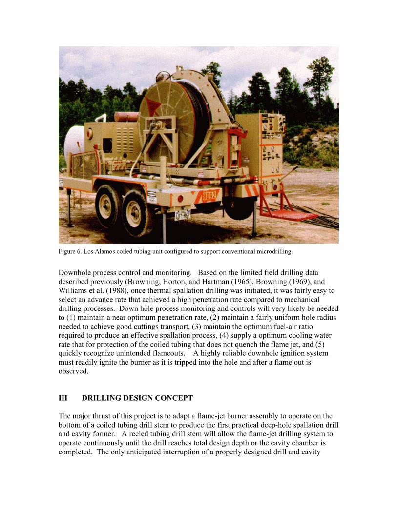
Figure 6. Los Alamos coiled tubing unit configured to support conventional microdrilling.
Downhole process control and monitoring. Based on the limited field drilling data described previously (Browning, Horton, and Hartman (1965), Browning (1969), and Williams et al. (1988), once thermal spallation drilling was initiated, it was fairly easy to select an advance rate that achieved a high penetration rate compared to mechanical drilling processes. Down hole process monitoring and controls will very likely be needed to (1) maintain a near optimum penetration rate, (2) maintain a fairly uniform hole radius needed to achieve good cuttings transport, (3) maintain the optimum fuel-air ratio required to produce an effective spallation process, (4) supply a optimum cooling water rate that for protection of the coiled tubing that does not quench the flame jet, and (5) quickly recognize unintended flameouts. A highly reliable downhole ignition system must readily ignite the burner as it is tripped into the hole and after a flame out is observed. III DRILLING DESIGN CONCEPT The major thrust of this project is to adapt a flame-jet burner assembly to operate on the bottom of a coiled tubing drill stem to produce the first practical deep-hole spallation drill and cavity former. A reeled tubing drill stem will allow the flame-jet drilling system to operate continuously until the drill reaches total design depth or the cavity chamber is completed. The only anticipated interruption of a properly designed drill and cavity
formation system will be a burner assembly failure or penetrating to rock that can not be thermally spalled. The spallation drilling concept is well developed at this point. The concept builds on drilling experience and projection in Browning, Horton, and Hartman (1965) and Browning (1969), from the drilling reported in Williams et al. (1988), and modeling results reported in MIT publications. Based on these inputs, an optimized drilling flame jet should be operated at the highest feasible exhaust velocity and should be advanced as fast as it can pass the no-go on the bottom of the burner into the spalled hole. The temperature of the exhaust should be controlled to maximize advance rate by adjusting the excess air injected into the burner. The critical elements of a prototype pre-commercial demonstration include:
1. A flame-jet burner assembly that will operate in a drilling and cavity formation environment for 24-hours or longer between maintenance interruptions.
2. A burner supply and control system that automatically supplies fuel air and cooling water to the burner assembly to operate a near optimum combustion thus preventing premature failure of the burner and protects the coiled tubing drill stem from over heating. While the control system can be located on the surface for shallow drilling, a downhole controller may be required to provide stable burner performance and a near optimum operating conduction in a deep drilling operation.
3. A coil tubing connector that mates the downhole burner (including the supply and control functions) assembly to the coiled-tubing drill stem
4. A reeled drill stem with internal utilities that provides an uninterrupted supply of fuel, air, and coiling water to the burner, and a cable with telemetry and electric power conductors needed to support downhole sensors, controllers, and a downhole flame igniter.
IV CAVITY FORMATION DESIGN CONCEPT The cavity formation concept is not very well developed at this point. The initial concept builds on drilling experience, from the Williams cavity formation experiment and modeling results reported in the previously -mentioned publications.. Based on these inputs, a cavity forming flame jet will be operated at a low exhaust velocity (large nozzle) and will be advanced as slow as feasible while still producing spalls that are small enough to be lifted thru the drill hole annulus. The temperature of the exhaust will be controlled and optimized to increase the spall production and reduce the size of the spalls that are produced. A cavity will be created starting at the bottom of the bored hole, starting with a modest recede rate on the flame jet burner and slowly decreasing the rate to create a cone shape to the bottom of the cavity that will serve to collect and concentrate spalls that are not removed in the exhaust system. When the withdraw rate is slowed to the point that spall production at the surface decreases or spall size increases to the point that transport is a concern and then withdraw rate will be increased slightly and
maintained until the top of the cavity depth is reached. It is anticipated that the cavity diameter produced by this simple burner concept will produce holes in excess of 12 inch on the prototype cavity former assembly. V FLAME-JET BURNER ASSEMBLY DESIGN CONCEPT Flame-jet burner. The flame-jet burner should be designed to maximize the spallation penetration rate during drilling and the hole volume creation during cavity formation. Based on equation (3) from Dey and Kranz (1985), their theory of thermal spallation predicts the penetration rate will vary as the heat transfer rate at the rock surface to the 0.85 power (0.83 to 0.87) for a Wiebel index between 15 and 20 which was based on mechanical induced stress failures in granite. When the revised parameters for the Wiebel index values between 7.7 and 12.8, based on thermally induced rock failures (Wilkinson and Tester, 1993b), are applied to equation (3) the penetration rate varies as the heat flux to the 0.76 power (0.72 to 0.81). Based on equation (2) from Dey and Kranz (1985), penetration rate will increase as surface temperature of the rock increases in the impingement region to between the 5.0 and 6.7 power for the mechanical parameters and to between 2.6 and 4.3 power for the thermal induced parameters. While this analysis takes the Dey and Kranz model well beyond their conclusions and is not believed to be highly reliable, its implication for the design of a research drilling system to evaluate the potential of downhole thermal spallation drill is clear. In order to investigate the upper bounds of the performance of thermal spallation, the burner should be designed to (i) maximize the potential heat flux into the hole bottom, and (ii) the burner exhaust jet in the boundary layer between the jet and the rock should attain the highest feasible temperature. In order to maximize the heat flux from the burner exhaust to the rock surface the various heat transfer mechanisms that apply or can be made to apply must be evaluated. Reviewing the referenced spallation drilling publications it is clear that researchers believe that impingement is the most effective process to transfer heat from a flame exhaust to a rock surface. No complete analysis was found to justify this conclusion but a calculation of the potential for conduction, forced convection, radiation, and subsonic impingement heat transport does appear to justify this conclusion when several simplifying conclusions are made. Browning, Horton, and Hartman (1965) apparently reached this conclusion through their experiments and also emphasized the fact that both flame temperature and jet velocity influence the drilling rate. From their drilling and kerfing (trenching) experiments in the laboratory and field they found that as the hole diameter is reduced, higher jet velocities are required to achieve spallation. Browning (1969) provides two performance charts for spallation drilling that describe drilling penetration rate as function of (1) combustion air flow, (2) delivery air pressure to the burner assembly, and (3) hole size. The advance rate and hole size are not independent variables but are linked so that, for a fixed burner operating point with constant air flow and pressure, the advance rate of the burner will control the hole size generated by the burner up to the predicted rate. Each chart lists a number of rock types
that Browning has divided into two classes based on spallation drilling results observed in the lab. Unfortunately, Browning shows only the performance predictions but fails to show the data points that were used to generate the curves that predict the drilling rate. Even so, the chart provides the best guide for selecting a fuel rate for the prototype burner assembly. Based on this guide and a 10 ft per hour target penetration rate, the burner should be capable of burning a minimum of 10 lb per hour propane and operate between stochiometric combustion plus 5% excess air for safety reasons and 100% excess air which is near the upper maximum flammability limit for commercial propane. The critical elements of a prototype flame-jet burner include:
1. 10 lb/hour propane combustion rate 2. 165 to 310 lb/hour air supply (24 to 45 SCFM) 3. A premixing section to achieve a uniform mixture and assure complete
combustion of the fuel to prevent fuel accumulation in the borehole annulus. 4. A combustion chamber sized to complete combustion at subsonic velocities at the
maximum volumetric flow rate. 5. A fuel air pre-mixer section that is sized to exceed the flame velocity at the
minimum fuel and air mixture flow rate. 6. An exhaust nozzle sized to produce a Mach 1.5 or greater exhaust velocity at near
stochiometric conditions for drilling. 7. An exhaust nozzle sized to produce a low, subsonic exhaust velocity at near
stochiometric conditions for cavity forming where impingement is not a significant heat transfer mechanism.
8. Fuel and air supplied at pressure to maintain the flow rates required to achieve supersonic flow in the exhaust nozzle.
9. A corrosion/erosion resistant no-go section at the bottom of the burner to prevent the burner from advancing into the spalled hole until the design diameter of the hole is achieved.
VI REELED DRILL STEM DESIGN CONCEPT The main function of the drill stem to support thermal spallation drilling is conveyance of the burner assembly and supply of fuel, air, cooling water, telemetry, and electric power. Because both fuel and air are conveyed down the drill stem, safety considerations will impact the detailed design of the drill stem. The Los Alamos design for a reeled drill stem has the following essential features.
1. A reeled external tube made of off-the-shelf coiled tubing. 2. Separate internal conduits for air, fuel, and cooling water some of which will be
annuli between internal stainless steel tubings. 3. A telemetry cable with sufficient conductors to support up to two down hole
sensors in the burner assembly and to provide electric power for the igniter if needed.
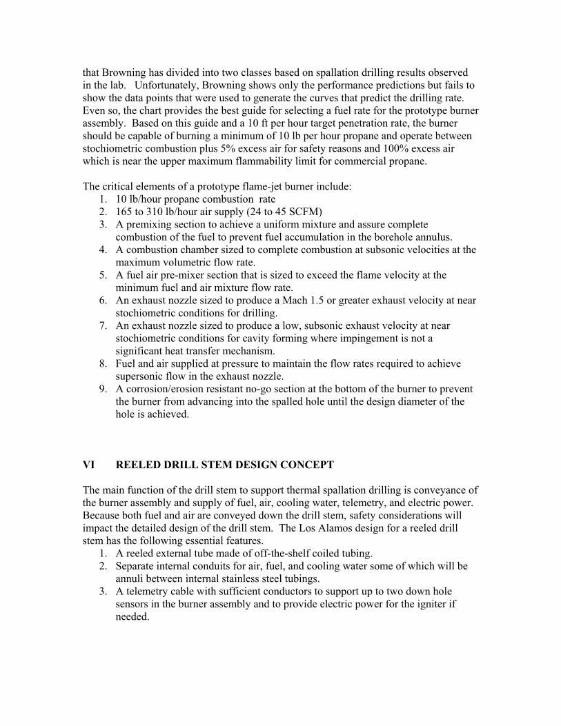
4. An internal configuration that separates the air flow from the propane flow with two steel boundaries and the cooling water to minimize the possibility of a propane air explosion within the coiled tubing in the event of a leak.
5. A connector sub on the bottomhole asembly that attaches the burner assembly to the coiled tubing.
6. A manifold on the surface end of the coiled tubing to connect the fuel, air, and water supplies to the proper conduits within the coiled tubing (Figure 7).
7. Both the connector sub and the manifold need to maintain the fuel-air separation trough use of at least two pressure boundaries and a stream of water that will dilute the fuel air mixture in the event of a near simultaneous failure of both pressure boundaries.
Figure 7. Design for manifold to conduct air, cooling water, fuel, and telemetry cable into reel end of coiled tubing while maintaining separation of air and fuel.
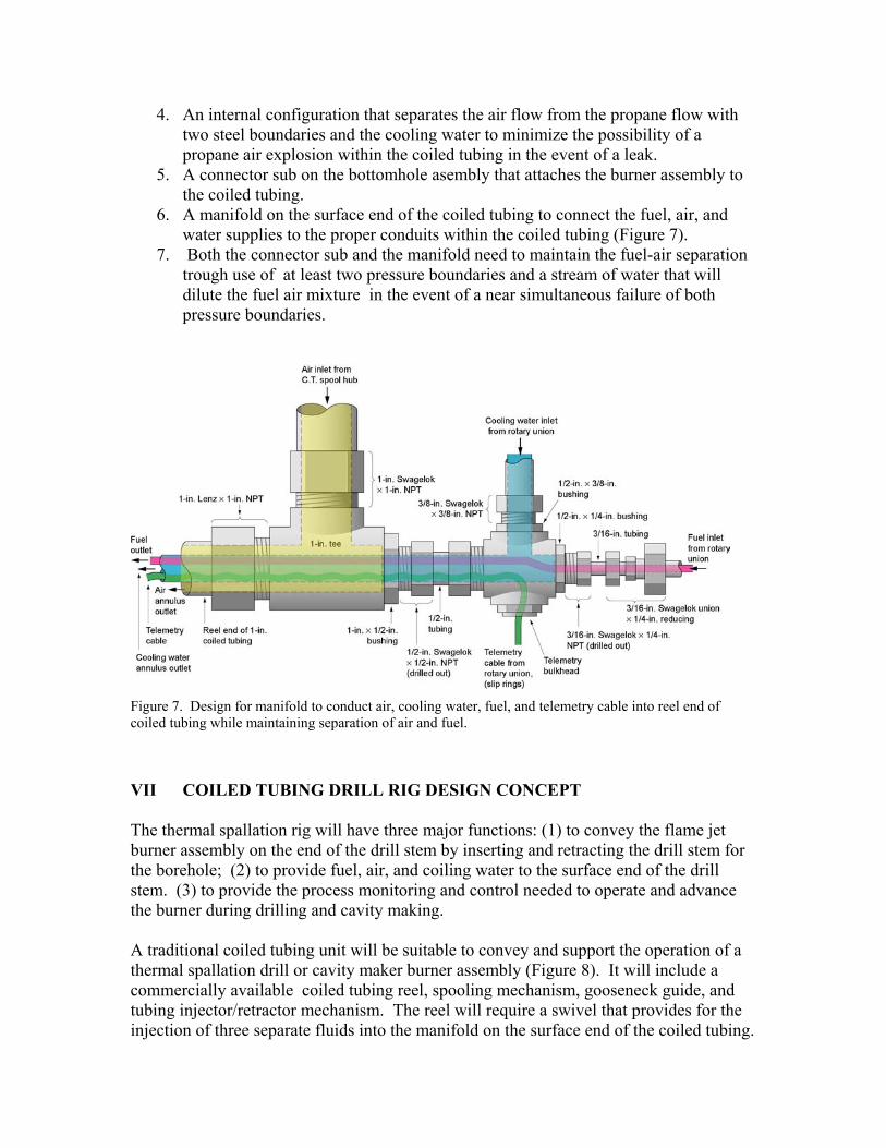
VII COILED TUBING DRILL RIG DESIGN CONCEPT The thermal spallation rig will have three major functions: (1) to convey the flame jet burner assembly on the end of the drill stem by inserting and retracting the drill stem for the borehole; (2) to provide fuel, air, and coiling water to the surface end of the drill stem. (3) to provide the process monitoring and control needed to operate and advance the burner during drilling and cavity making. A traditional coiled tubing unit will be suitable to convey and support the operation of a thermal spallation drill or cavity maker burner assembly (Figure 8). It will include a commercially available coiled tubing reel, spooling mechanism, gooseneck guide, and tubing injector/retractor mechanism. The reel will require a swivel that provides for the injection of three separate fluids into the manifold on the surface end of the coiled tubing.
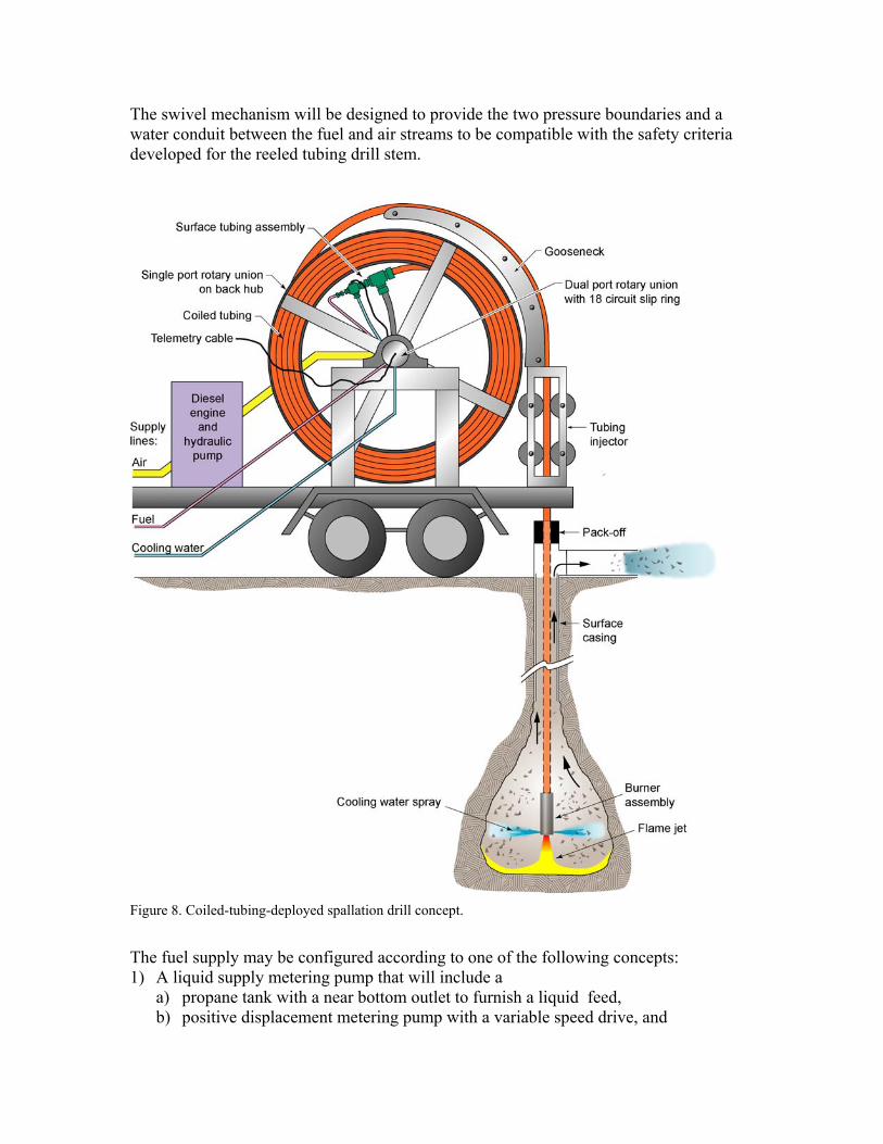
The swivel mechanism will be designed to provide the two pressure boundaries and a water conduit between the fuel and air streams to be compatible with the safety criteria developed for the reeled tubing drill stem.
Figure 8. Coiled-tubing-deployed spallation drill concept.
The fuel supply may be configured according to one of the following concepts: 1) A liquid supply metering pump that will include a
a) propane tank with a near bottom outlet to furnish a liquid feed, b) positive displacement metering pump with a variable speed drive, and
c) heat exchanger to vaporize the high pressure propane. 2) A liquid supply affinity law pump with liquid control that will include a:
a) propane tank with a near bottom outlet to furnish a liquid feed, b) centrifugal pump (affinity law) with a constant speed drive, c) liquid flow meter, d) liquid flow control valve, and e) heat exchanger to vaporize the high pressure propane.
3) A liquid supply affinity law pump with gas control that will include a; a) propane tank with a near bottom outlet to furnish a liquid feed, b) centrifugal pump (affinity law) with a constant speed drive, c) heat exchanger to vaporize the high pressure propane, d) gas flow meter, and e) gas flow control valve.
4) A high pressure tank supply that will include a: a) 500 psi MAWP propane storage tank with a vapor outlet in the top of the tank,hot
water circulation system and heat exchanger to heat a water bath to temperatures as high as 200 degree F using heat from inter and after coolers on the air compressor or from the spallation exhaust flow line
b) Propane vapor flow meter In 4) the water supply will be feed from water storage tank through a variable speed drive positive displacement pump or a centrifugal pump, flow meter, and control valve. The air supply will be a reciprocating or rotary air compressor. A single stage compressor will be marginal so a two-stage compressor will be needed to provide the performance desired. An air meter and control valve will be needed to control the flow rate. VIII CALCULATIONS AND MODELING This section will be completed after calculations and models are redone and verified. The calculation were completed on MathCad worksheets using the function mode so uncertain variables can readily revised and the calculation redone as new experimental data become available. A brief summary of work performed at NM Tech and Los Alamos is follows:
1. Calculated the stochiometric combustion reactant and product flow rates for a variable fuel rate and excess air ratio.
2. Calculated the stochiometric and excess air combustion temperatures assuming and adiabatic burner assembly.
3. Calculated the pressure losses in the coiled tubing transport conduits for fuel, air, and cooling water. Variables include surface temperature and pressure, fuel flow rate, excess air ratio, and cooling water rate.
4. Set up a work sheet to estimated pressure losses in the annulus and the sheet is 50% complete. Variables include bottom-hole temperature and pressure, penetration rate, fuel flow rate, excess air ratio, and cooling water rate.
5. Set up work sheet to estimate heat transport between the various flow conduits within and the annulus external to the coiled tubing. The sheet is 50% complete.
a. Performed preliminary calculations to size the exhaust nozzle for the burner and calculated the pressures and flows needed to achieve a Mach 1.5 exhaust jet (Emanuel, 1986).
IX DEMONSTRATION OF SUBSYSTEMS
Prototype Burner Tests
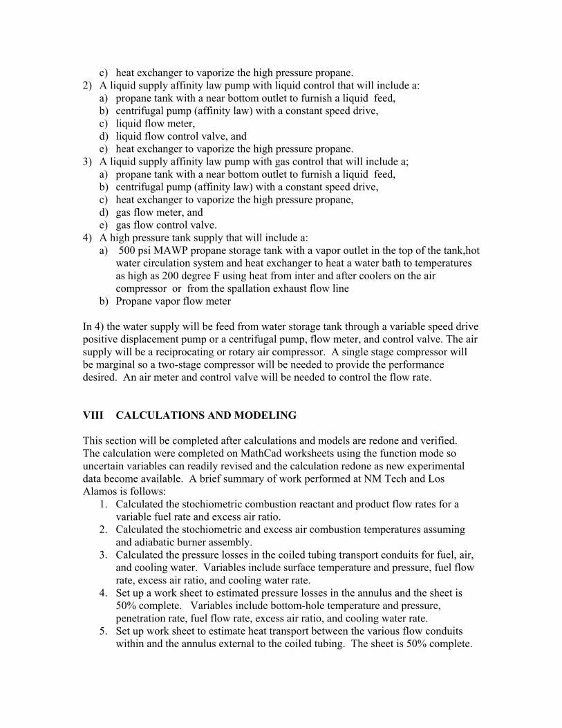
The objectives of the prototype burner tests are to achieve burner operation with a supersonic exhaust at a fuel rate of 10 lb/hr which is thought to allow a nominal 10 ft/hr penetration rate in a suitable hard rock and to demonstrate that the burner fed fuel, air and water through a single pipe can be used to penetrate and create a cavity in a suitable hard rock. For identification purposes we call the burners used in these two test functions the bench burner and the rig burner (or the 10 foot test burner). Due to time factors, both efforts are conducted simultaneously even though results from the bench tests are used in designing the rig burner. Bench top burner. This burner is an evolution of burners previously developed at NM Tech. The burner features include an air-propane mixing zone, an ignition zone, a flame holding zone, a combustion chamber and an exit nozzle (Figure 9). The exit nozzle is easily removed and at present we use two sizes: a throat diameter of 0.339 inches which should produce a supersonic exhaust at the 10 lb/hr fuel rate and a throat diameter of 0.438 inches, which will be subsonic at the target fuel rate but is easy to ignite.
Figure 9. New Mexico Tech bench burner assembly.
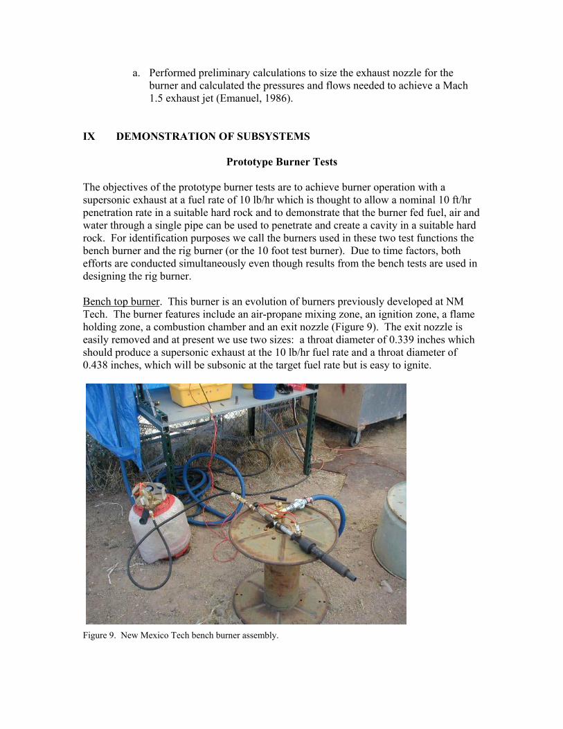
There have been two problems encountered in developing the bench burner to meet the target fuel rates and exhaust conditions. The first was an inability to ignite. This was solved by improving the air-fuel mixing with the installation of an on-hand mixing venturi (originally used as a venturi eductor in a previous research project) (Figure 10). The second was an inability to achieve the target fuel rates. This was solved by increasing the diameter of the flame holder region (this modification also increased the length of the burner after the flame holder).
Figure 10. Air-fuel mixing section for bench burner with (left to right) propane hose connecter, coupling, flow tee with air inlet on side, venturi, coupling, and mixing pipe nipple.
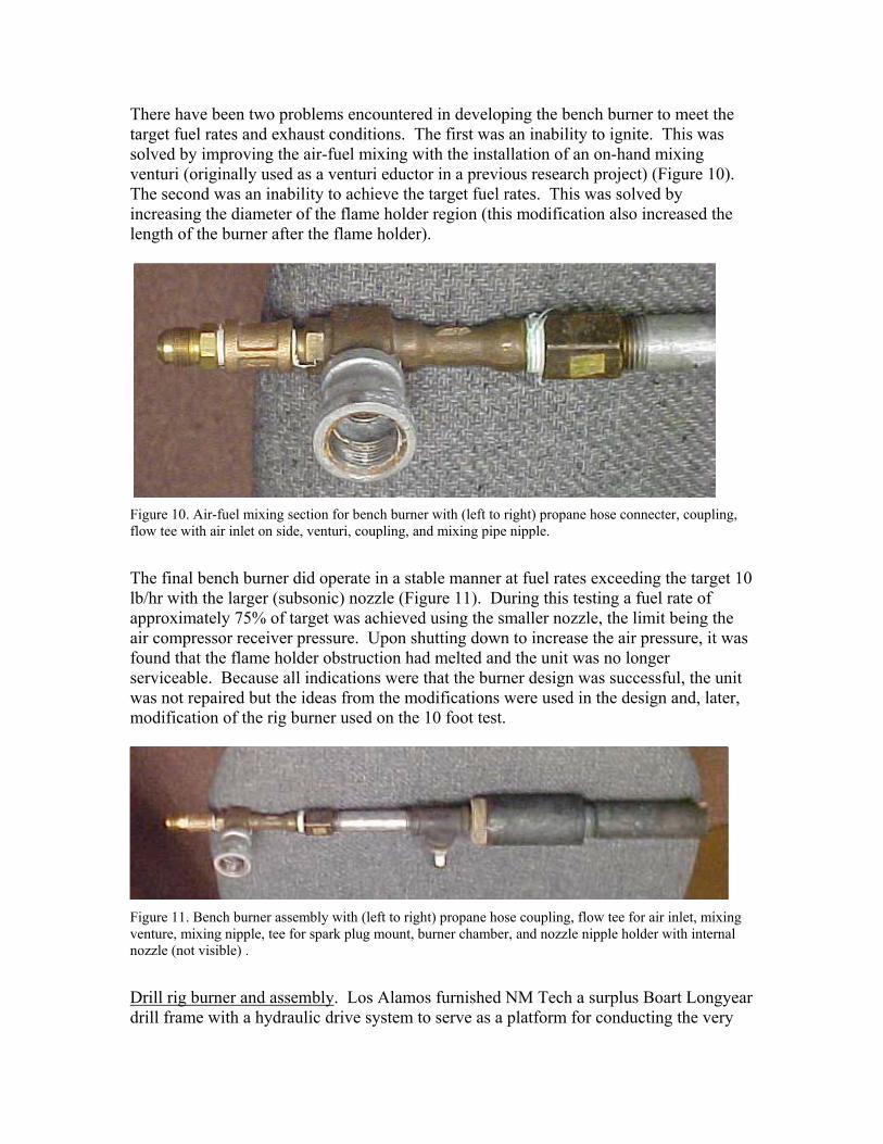
The final bench burner did operate in a stable manner at fuel rates exceeding the target 10 lb/hr with the larger (subsonic) nozzle (Figure 11). During this testing a fuel rate of approximately 75% of target was achieved using the smaller nozzle, the limit being the air compressor receiver pressure. Upon shutting down to increase the air pressure, it was found that the flame holder obstruction had melted and the unit was no longer serviceable. Because all indications were that the burner design was successful, the unit was not repaired but the ideas from the modifications were used in the design and, later, modification of the rig burner used on the 10 foot test.
Figure 11. Bench burner assembly with (left to right) propane hose coupling, flow tee for air inlet, mixing venture, mixing nipple, tee for spark plug mount, burner chamber, and nozzle nipple holder with internal nozzle (not visible) .
Drill rig burner and assembly. Los Alamos furnished NM Tech a surplus Boart Longyear drill frame with a hydraulic drive system to serve as a platform for conducting the very
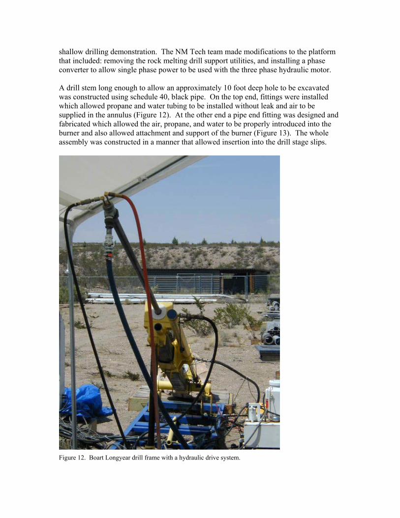
shallow drilling demonstration. The NM Tech team made modifications to the platform that included: removing the rock melting drill support utilities, and installing a phase converter to allow single phase power to be used with the three phase hydraulic motor. A drill stem long enough to allow an approximately 10 foot deep hole to be excavated was constructed using schedule 40, black pipe. On the top end, fittings were installed which allowed propane and water tubing to be installed without leak and air to be supplied in the annulus (Figure 12). At the other end a pipe end fitting was designed and fabricated which allowed the air, propane, and water to be properly introduced into the burner and also allowed attachment and support of the burner (Figure 13). The whole assembly was constructed in a manner that allowed insertion into the drill stage slips.
Figure 12. Boart Longyear drill frame with a hydraulic drive system.
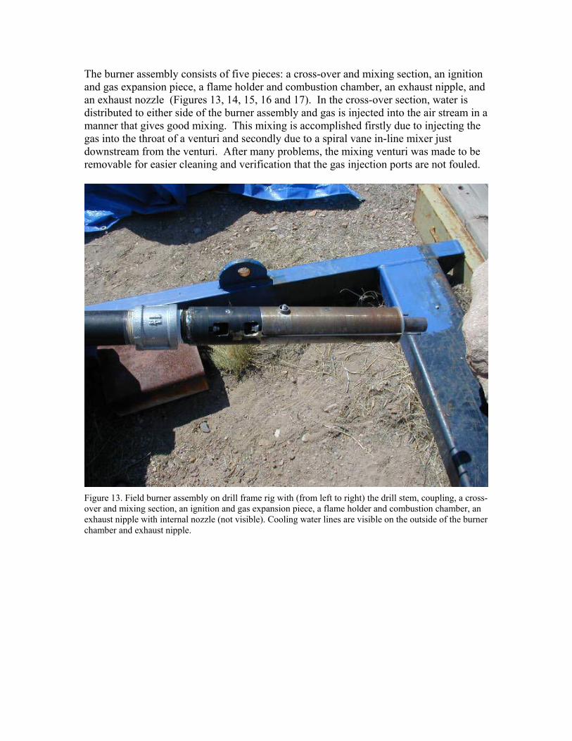
The burner assembly consists of five pieces: a cross-over and mixing section, an ignition and gas expansion piece, a flame holder and combustion chamber, an exhaust nipple, and an exhaust nozzle (Figures 13, 14, 15, 16 and 17). In the cross-over section, water is distributed to either side of the burner assembly and gas is injected into the air stream in a manner that gives good mixing. This mixing is accomplished firstly due to injecting the gas into the throat of a venturi and secondly due to a spiral vane in-line mixer just downstream from the venturi. After many problems, the mixing venturi was made to be removable for easier cleaning and verification that the gas injection ports are not fouled.
Figure 13. Field burner assembly on drill frame rig with (from left to right) the drill stem, coupling, a cross-over and mixing section, an ignition and gas expansion piece, a flame holder and combustion chamber, an exhaust nipple with internal nozzle (not visible). Cooling water lines are visible on the outside of the burner chamber and exhaust nipple.
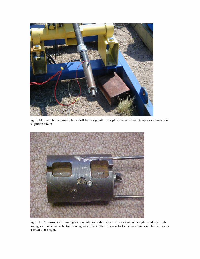
Figure 14. Field burner assembly on drill frame rig with spark plug energized with temporary connection to ignition circuit.
Figure 15. Cross-over and mixing section with in-the-line vane mixer shown on the right hand side of the mixing section between the two cooling water lines. The set screw locks the vane mixer in place after it is inserted to the right.
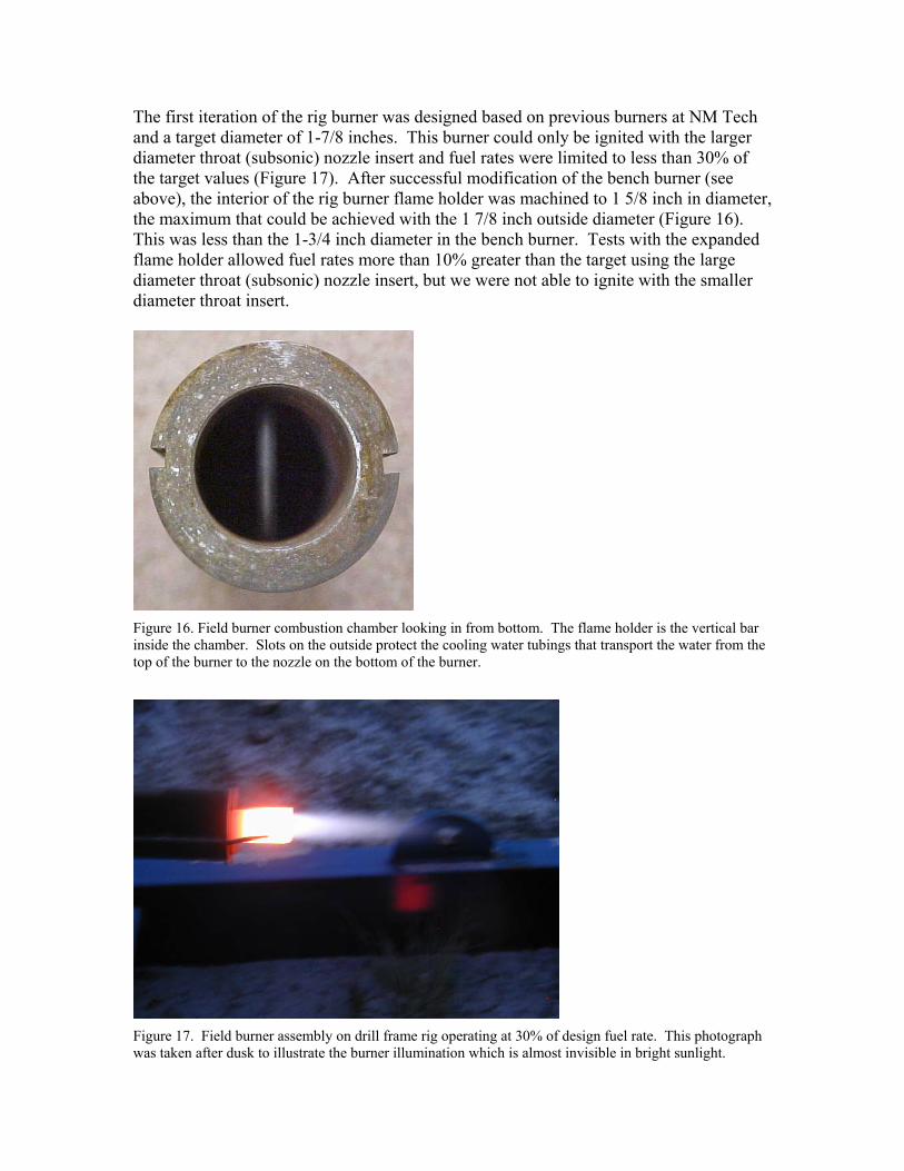
The first iteration of the rig burner was designed based on previous burners at NM Tech and a target diameter of 1-7/8 inches. This burner could only be ignited with the larger diameter throat (subsonic) nozzle insert and fuel rates were limited to less than 30% of the target values (Figure 17). After successful modification of the bench burner (see above), the interior of the rig burner flame holder was machined to 1 5/8 inch in diameter, the maximum that could be achieved with the 1 7/8 inch outside diameter (Figure 16). This was less than the 1-3/4 inch diameter in the bench burner. Tests with the expanded flame holder allowed fuel rates more than 10% greater than the target using the large diameter throat (subsonic) nozzle insert, but we were not able to ignite with the smaller diameter throat insert.
Figure 16. Field burner combustion chamber looking in from bottom. The flame holder is the vertical bar inside the chamber. Slots on the outside protect the cooling water tubings that transport the water from the top of the burner to the nozzle on the bottom of the burner.
Figure 17. Field burner assembly on drill frame rig operating at 30% of design fuel rate. This photograph was taken after dusk to illustrate the burner illumination which is almost invisible in bright sunlight.
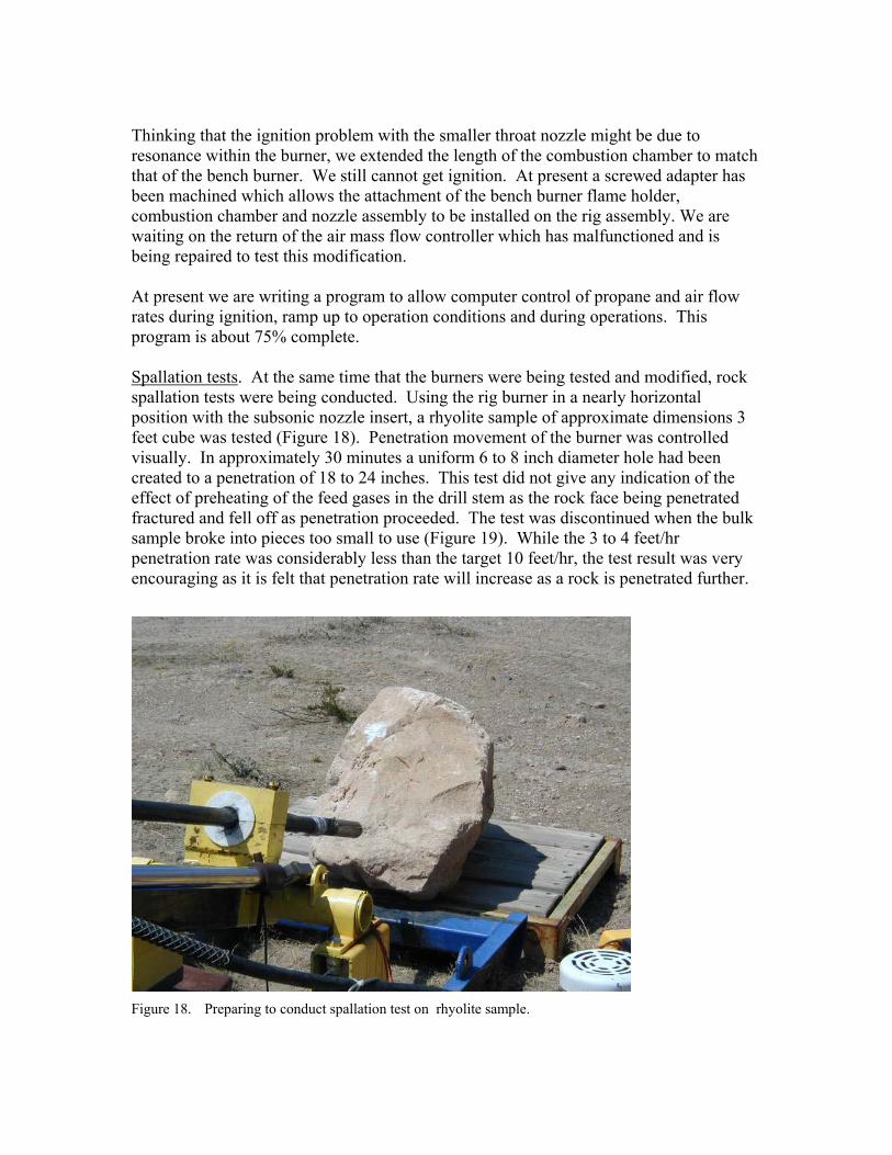
Thinking that the ignition problem with the smaller throat nozzle might be due to resonance within the burner, we extended the length of the combustion chamber to match that of the bench burner. We still cannot get ignition. At present a screwed adapter has been machined which allows the attachment of the bench burner flame holder, combustion chamber and nozzle assembly to be installed on the rig assembly. We are waiting on the return of the air mass flow controller which has malfunctioned and is being repaired to test this modification. At present we are writing a program to allow computer control of propane and air flow rates during ignition, ramp up to operation conditions and during operations. This program is about 75% complete. Spallation tests. At the same time that the burners were being tested and modified, rock spallation tests were being conducted. Using the rig burner in a nearly horizontal position with the subsonic nozzle insert, a rhyolite sample of approximate dimensions 3 feet cube was tested (Figure 18). Penetration movement of the burner was controlled visually. In approximately 30 minutes a uniform 6 to 8 inch diameter hole had been created to a penetration of 18 to 24 inches. This test did not give any indication of the effect of preheating of the feed gases in the drill stem as the rock face being penetrated fractured and fell off as penetration proceeded. The test was discontinued when the bulk sample broke into pieces too small to use (Figure 19). While the 3 to 4 feet/hr penetration rate was considerably less than the target 10 feet/hr, the test result was very encouraging as it is felt that penetration rate will increase as a rock is penetrated further.
Figure 18. Preparing to conduct spallation test on rhyolite sample.
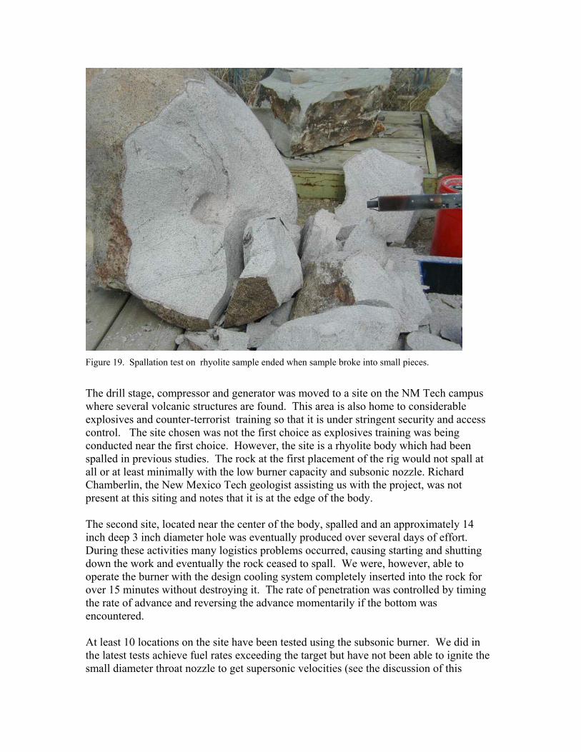
Figure 19. Spallation test on rhyolite sample ended when sample broke into small pieces.
The drill stage, compressor and generator was moved to a site on the NM Tech campus where several volcanic structures are found. This area is also home to considerable explosives and counter-terrorist training so that it is under stringent security and access control. The site chosen was not the first choice as explosives training was being conducted near the first choice. However, the site is a rhyolite body which had been spalled in previous studies. The rock at the first placement of the rig would not spall at all or at least minimally with the low burner capacity and subsonic nozzle. Richard Chamberlin, the New Mexico Tech geologist assisting us with the project, was not present at this siting and notes that it is at the edge of the body. The second site, located near the center of the body, spalled and an approximately 14 inch deep 3 inch diameter hole was eventually produced over several days of effort. During these activities many logistics problems occurred, causing starting and shutting down the work and eventually the rock ceased to spall. We were, however, able to operate the burner with the design cooling system completely inserted into the rock for over 15 minutes without destroying it. The rate of penetration was controlled by timing the rate of advance and reversing the advance momentarily if the bottom was encountered. At least 10 locations on the site have been tested using the subsonic burner. We did in the latest tests achieve fuel rates exceeding the target but have not been able to ignite the small diameter throat nozzle to get supersonic velocities (see the discussion of this
subject above). The spallation test results after the one 14 inch deep hole have all been similar; initially spallation proceeds rapidly to a penetration to 3 to 6 inches when it ceases. Fractures in the direction of penetration have been observed and it is possible that if penetration were begun at some depth, which would allow the rock to withstand higher stresses without fracturing, spallation would proceed. It is also possible that higher flame velocities would spall faster, allowing faster penetration to depth before heating of the rock creates high bulk stress in the rock body. To see if the rock will spall at if we start at some depth, an 18 inch deep by 2 inch diameter pilot hole has been drilled in the rock using an electric percussion drill. The test has not yet been conducted as we are trying to modify the burner to allow ignition with the supersonic nozzle and have the air mass flow controller out for repairs.
Coiled-Tubing Drill Stem Design and Procurement The Los Alamos coiled tubing unit is presently configured to operate with up to 1000-ft of 1-inch coiled tubing. In previous conventional drilling work, we had determine that reel operations were greatly improved by limiting the length of the coiled tubing to 800 ft which was set practical limit of the units capability. In theory, it could be reconfigured, at considerable expense, to operate with approximately 500-ft of 1-1/4 inch coiled tubing. There are serious concerns that the performance would be very poor without a complete redesign that would take almost a long and cost almost as much as design and build of a new coiled tubing unit. Therefore we elected to design a 1-inch OD coiled tubing drill stem. Calculations were performed to determine if an 800-ft long coiled-tubing could be designed with internal stainless steel tubing lines to produce 3 flow conduits, provide the safety feature specified earlier, and have small enough friction losses in the three conduits while operating the burner at a 10-lb/hr propane flow rate with pumps and compressors with a 500-psi discharge pressure. Flow models were used to calculate the pressure loss in the propane, cooling water, and air conduits for various combinations of tube sizes and assuming that a 0.22-inch OD telemetry cable would be run inside the water annulus beside the propane tube. A near optimum design was developed that included in internal propane tube with a 0.179-inch ID in a tube with a 3/16-inch OD, a water flow annulus with and ID of 0.460-inch in a tube with a 1/2-inch OD and an air flow annuli with a 0.850-inch ID inside the 1-inch coiled tubing. A specification was prepared and submitted to potential vendors to determine the availability of the small tubings in continuous long lengths and the willingness of vendors to fabricate a single small order for demonstration purposes. It was decided to procure a 200-ft long string instead of a full 800-ft string for the first field demonstrations with the hope that the burner assembly could be run on coiled tubing and operated using fairly low pressure off-the shelf pumps and compressors to supply the propane, water, and air to the coiled tubing. The only response to our solicitation proposed the following combination of internal tubes based on the availability of stainless steel tubing.
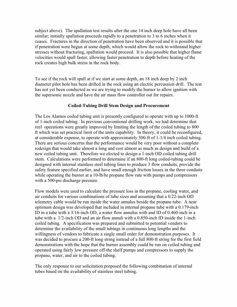
1. 1-inch OD, 0.826-inch ID, HS –70 (70,000 psi minimum yield stress carbon steel) coiled tubing 207-ft long
2. 1/2-inch OD, 0.430-inch ID, 316L stainless steel tubing 208-ft long 3. 0.187-inch OD, 0.131-inch ID, 304L stainless steel tubing 209-ft long 4. Multi Conductor Cable, 8-pair #MASBX6399 209-ft long
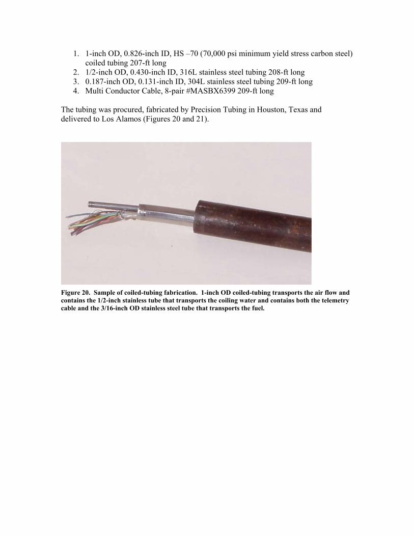
The tubing was procured, fabricated by Precision Tubing in Houston, Texas and delivered to Los Alamos (Figures 20 and 21).
Figure 20. Sample of coiled-tubing fabrication. 1-inch OD coiled-tubing transports the air flow and contains the 1/2-inch stainless tube that transports the coiling water and contains both the telemetry cable and the 3/16-inch OD stainless steel tube that transports the fuel.
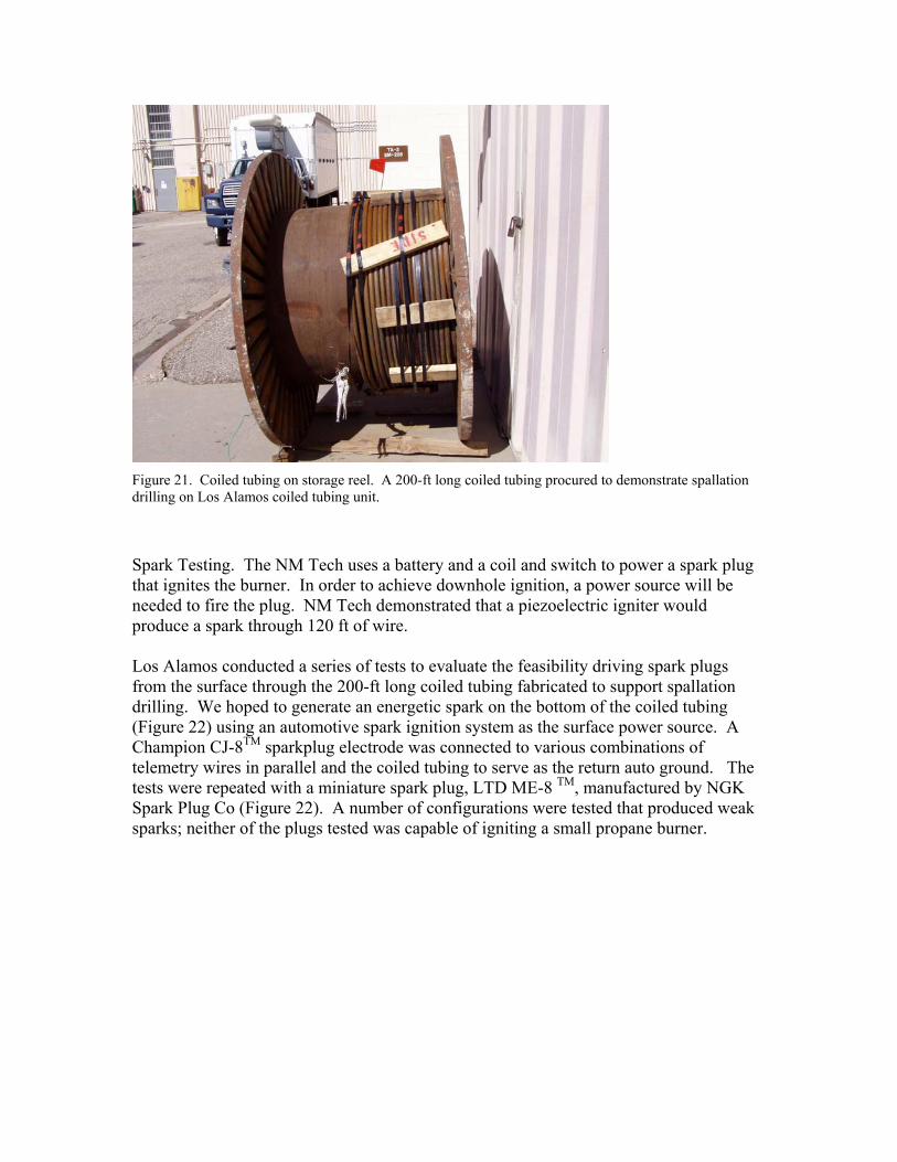
Figure 21. Coiled tubing on storage reel. A 200-ft long coiled tubing procured to demonstrate spallation drilling on Los Alamos coiled tubing unit.
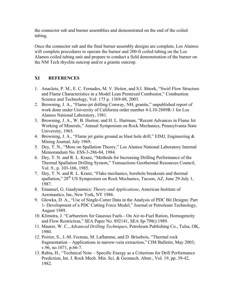
Spark Testing. The NM Tech uses a battery and a coil and switch to power a spark plug that ignites the burner. In order to achieve downhole ignition, a power source will be needed to fire the plug. NM Tech demonstrated that a piezoelectric igniter would produce a spark through 120 ft of wire. Los Alamos conducted a series of tests to evaluate the feasibility driving spark plugs from the surface through the 200-ft long coiled tubing fabricated to support spallation drilling. We hoped to generate an energetic spark on the bottom of the coiled tubing (Figure 22) using an automotive spark ignition system as the surface power source. A Champion CJ-8TM sparkplug electrode was connected to various combinations of telemetry wires in parallel and the coiled tubing to serve as the return auto ground. The tests were repeated with a miniature spark plug, LTD ME-8 TM, manufactured by NGK Spark Plug Co (Figure 22). A number of configurations were tested that produced weak sparks; neither of the plugs tested was capable of igniting a small propane burner.
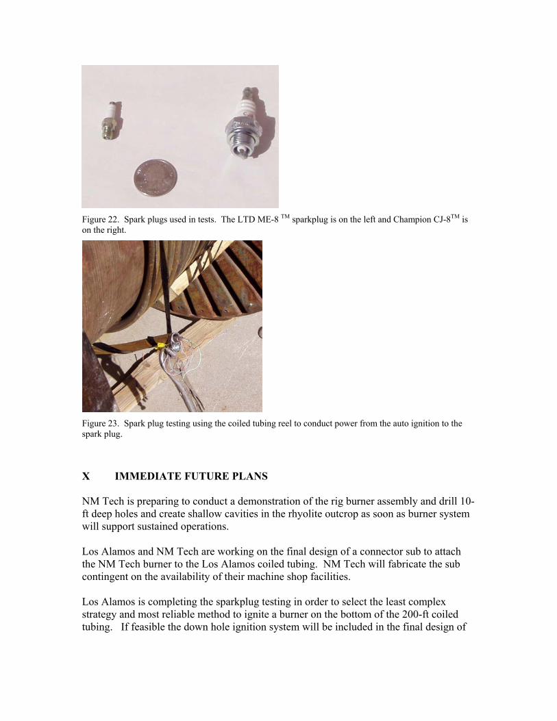
Figure 22. Spark plugs used in tests. The LTD ME-8 TM sparkplug is on the left and Champion CJ-8TM is on the right.
Figure 23. Spark plug testing using the coiled tubing reel to conduct power from the auto ignition to the spark plug.
X IMMEDIATE FUTURE PLANS NM Tech is preparing to conduct a demonstration of the rig burner assembly and drill 10-ft deep holes and create shallow cavities in the rhyolite outcrop as soon as burner system will support sustained operations. Los Alamos and NM Tech are working on the final design of a connector sub to attach the NM Tech burner to the Los Alamos coiled tubing. NM Tech will fabricate the sub contingent on the availability of their machine shop facilities. Los Alamos is completing the sparkplug testing in order to select the least complex strategy and most reliable method to ignite a burner on the bottom of the 200-ft coiled tubing. If feasible the down hole ignition system will be included in the final design of
the connector sub and burner assemblies and demonstrated on the end of the coiled tubing. Once the connector sub and the final burner assembly designs are complete, Los Alamos will complete procedures to operate the burner and 200-ft coiled tubing on the Los Alamos coiled tubing unit and prepare to conduct a field demonstration of the burner on the NM Tech rhyolite outcrop and/or a granite outcrop. XI REFERENCES 1. Anacleto, P. M., E. C. Fernades, M. V. Heitor, and S.I. Shtork, “Swirl Flow Structure
and Flame Characteristics in a Model Lean Premixed Combustor,” Combustion Science and Technology, Vol: 175 p. 1369-88, 2003.
2. Browning, J. A., “Flame-jet drilling Conway, NH, granite,” unpublished report of work done under University of California order number 4-L10-2889R-1 for Los Alamos National Laboratory, 1981.
3. Browning, J. A., W. B. Horton; and H. L. Hartman, “Recent Advances in Flame Jet Working of Minerals,” Annual Symposium on Rock Mechanics, Pennsylvania State University, 1965.
4. Browning, J. A., “Flame jet gains ground as blast hole drill,” EIMJ, Engineering & Mining Journal, July 1969.
5. Dey, T. N., “More on Spallation Theory,” Los Alamos National Laboratory Internal Memorandum No. ESS-3-286-84, 1984.
6. Dey, T. N. and R. L. Kranz, “Methods for Increasing Drilling Performance of the Thermal Spallation Drilling System,” Transactions Geothermal Resources Council, Vol. 9., p. 103-106, 1985.
7. Dey, T. N. and R. L. Kranz, “Flake mechanics, borehole breakouts and thermal spallation,” 28th US Symposium on Rock Mechanics, Tucson, AZ, June 29-July 1, 1987.
8. Emanuel, G. Gasdynamics: Theory and Applications, American Institute of Aeronautics, Inc, New York, NY 1986.
9. Glowka, D. A., “Use of Single-Cutter Data in the Analysis of PDC Bit Designs: Part 1- Development of a PDC Cutting Force Model,” Journal or Petroleum Technology, August 1989.
10. Klimstra, J. “Carburetors for Gaseous Fuels - On Air-to-Fuel Ration, Homogeneity and Flow Restriction,” SEA Paper No. 892141, SEA Sp-798():1989.
11. Maurer, W. C., Advanced Drilling Techniques, Petroleum Publishing Co., Tulsa, OK, 1980.
12. Poirier, S., J.-M. Fecteau, M. Laflamme, and D. Brisebois, “Thermal rock fragmentation – Applications in narrow-vein extraction,” CIM Bulletin; May 2003; v.96, no.1071, p.66-7.
13. Rabia, H., “Technical Note – Specific Energy as a Criterions for Drill Performance Prediction, Int. J. Rock Mech. Min. Sci. & Geomech. Abstr., Vol. 19, pp. 39-42, 1982.
14. Rauenzahn, R. and J. W. Tester, “Flame-Jet Induced Thermal Spallation as a Method of Rapid Drilling and Cavity Formation,” Proc. 60th ATCE , Society of Petroleum Engineers Paper 14331, Las Vegas, NV, September 22-25, 1985.
15. Rauenzahn, R. and J. W. Tester, “Rock failure mechanisms of flame-jet thermal spallation drilling. Theory and experimental testing,” International journal of rock mechanics and mining sciences & geomechanics abstracts [0148-9062] vol: 26 iss: 5 pg: 381 – 399, 1989
16. Rauenzahn, R. and J. W. Tester, “Numerical simulation and field testing of flame-jet thermal spallation drilling-1. Model development” International Journal of Heat and Mass Transfer, Vol. 34 Issue 3, p 795-808, 1991.
17. Rauenzahn, R. and J. W. Tester, “Numerical simulation and field testing of flame-jet thermal spallation drilling-2. Experimental verification” International Journal of Heat and Mass Transfer, Vol. 34 Issue 3, p. 809-817, 1991.
18. Rowley, D. S. and F. C. Appl, “Analysis of Surface Set Diamond Bit Performance,” SPE 2242, 43rd Annual Fall Meeting SPE, Houston, TX, September 29- October 2, 1969.
19. Shchelking, K. I. and Ya. K. Troshin, Gasdynamics of Combustion, Mono Book Corp., Baltimore, 1965.
20. Wilkinson, M. A. and J. W. Tester, “ Computational modeling of the gas-phase transport phenomena during flame-jet thermal spallation drilling,” J. Heat Mass. Transfer, vol. 36, No. 14, p. 3459-3475, 1993 a.
21. Wilkinson, M. A. and J. W. Tester, “Experimental-Measurement of Surface Temperatures During Flame-Jet Induced Thermal Spallation,” Rock mechanics and rock engineering, Vol. 26 Issue: 1, p. 29-62, 1993 b.
22. Williams, R. E., R. M. Potter, S. Miska, “Experiments in Thermal Spallation of Various Rocks,” Journal of Energy Resources Technology, Vol. 118/3, March 1996.
23. Williams, R. E., R. E. Bretz, and D. Ayon, “Spallation Using Propane Fuel, Course Outline for CH E 491 01, Fall Semester, 1999.
24. Williams, R. E. et. al., “Advancement in Thermal Spallation Drilling Technology, Los Alamos National Laboratory Report, LA-11391-MS, September 1988.
25. Williams, R. E., “Thermal Spallation Drilling,” Los Alamos National Laboratory Mini-review, LALP-84-60, February 1985.
26. Precession Tube Technology, Inc., “Coiled Tubing Technical Handbook,” http://www.precisio.com/CTTechBook.htm, page 4, revised June 1999.