Embed Size (px)
Citation preview
doi: 10.1111/j.1460-2695.2005.00919.x
Cohesive-zone modelling of the deformation and fractureof spot-welded joints
M. N. CAVALLI1, M. D. THOULESS2,3 and Q. D. YANG4
1Department of Mechanical Engineering, University of North Dakota, Grand Forks, ND 58202-8359; 2Department of Mechanical Engineering,3Department of Materials Science and Engineering, University of Michigan, Ann Arbor, MI, and 4Rockwell Scientific Company, Thousand Oaks,CA, USA
Received in final form 2 April 2005
A B S T R A C T The deformation and failure of spot-welded joints have been successfully modelled usinga cohesive-zone model for fracture. This has been accomplished by implementing a user-defined, three-dimensional, cohesive-zone element within a commercial finite-elementpackage. The model requires two material parameters for each mode of deformation.Results show that the material parameters from this type of approach are transferable foridentical spot welds in different geometries where a single parameter (such as maximumstress) is not. The approach has been demonstrated using a model system consisting ofspot-welded joints made from 5754 aluminium sheets. The techniques for determining thecohesive fracture parameters for both nugget fracture and nugget pullout are describedin this paper. It has been demonstrated that once the appropriate cohesive parametersfor a weld are determined, quantitative predictions can be developed for the strengths,deformations and failure mechanisms of different geometries with nominally identicalwelds.
Keywords cohesive-zone modelling; finite element modelling; fracture; resistancespot-welding.
N O M E N C L A T U R E G = shear modulus�IN = mode-I nugget fracture toughness�IIN = mode-II nugget fracture toughness�IIIN = mode-III nugget fracture toughness
�IP = mode-I pullout fracture toughness�IIP = mode-II pullout fracture toughness�IIIP = mode-III pullout fracture toughnessGI = mode-I energy release rateGII = mode-II energy release rateGIII = mode-III energy release rate
E = Young’s modulus�σ N = mode-I nugget cohesive strength�τN = mode-II (and III) nugget cohesive strength�σ P = mode-I pullout cohesive strength�τP = mode-II (and III) pullout cohesive strength
I N T R O D U C T I O N
Structural joints between thin metal sheets are crucialcomponents of many engineering designs. Methods of
Correspondence: M. N. Cavalli. E-mail: [email protected]
joining metal sheets include clamping them together withbolts or rivets, chemically bonding them with an interme-diate layer such as an adhesive, or welding them together.Resistance spot-welding, which makes use of the contactresistance between metal parts to induce localized meltingwhen an electric current is applied, is widely used in the
c© 2005 Blackwell Publishing Ltd. Fatigue Fract Engng Mater Struct 28, 861–874 861
862 M. N. CAVALL I et al.
automotive industry. A complete understanding of howto analyse the deformation and fracture of spot-weldedjoints, and how to use this analysis to make predictionsabout their performance, would greatly enhance the effi-cient design of safe automotive structures.
One method of analysing spot-welded joints is to calcu-late the stress distribution, and to determine the regionswhere the stresses are elevated.1–3 However, while theknowledge of the locations of the highest stresses can helppredict where a spot-welded structure is likely to fracture,it cannot, by itself, predict the load at which failure will oc-cur. Such predictions require both suitable failure criteriaand a method for implementing these criteria into numer-ical calculations. Existing failure criteria for spot-weldedjoints generally share the starting assumption that a sin-gle parameter (e.g. a critical stress or force) characterizesthe failure of a spot weld that is subjected to a pure stateof stress (e.g. shear or tension). In other words, there isan implicit assumption that it is possible to use a singlestrength parameter as the sole failure criterion under sim-ple loading conditions. For example, Lee et al.4 and Linet al.5 based their failure criterion on the average tensileand shear strengths of a weld. Wung and co-authors6,7 de-veloped a similar criterion introducing a bending momentand a torque as two additional modes of loading a weld.
These strength-based approaches for predicting the per-formance of a weld appear to work quite well if the geome-try of the joint is kept fairly constant. Substantial changesin the geometry may change the relative stress levels indifferent regions of the weld, fundamentally affecting theaverage stress at which failure occurs. This is a classicissue in fracture, and it is well established that energy-based failure criteria need to be included in any quanti-tative fracture analysis. However, the use of only energy-based failure criteria is not appropriate unless the scale ofplastic deformation in a structure is much less than anycharacteristic length. Owing to large-scale plasticity thataccompanies fracture, this condition is generally violatedwith any spot-welded sheet metal. Fracture problems inwhich plastic deformation is significant can be analysedby the use of cohesive-zone models that incorporate bothstrength and energy criteria for fracture.8–16 This paperprovides the first example of using cohesive-zone modelfor analysing welded structures, demonstrating an experi-mental determination of the cohesive parameters and theiruse in predicting the strength of joints.
The approach developed for this paper is a direct exten-sion of earlier work on adhesive joints.8–11 Standard finite-element methods are used to model the deformation of theadherends. Bonding across any potential rupture plane isrepresented by a cohesive law that is characterized by twoparameters: a cohesive strength and a fracture energy. Rel-ative displacement of the rupture planes is resisted by thecohesive stresses. Fracture occurs when a critical relative
displacement (corresponding to the critical fracture en-ergy) is reached.
The earlier work on adhesive joints was successful inpart because of the significant numerical simplificationsthat resulted from not attempting to model the details ofthe adhesive. The role of the adhesive in the analysis wasreduced to one of merely providing tractions across theinterface. These tractions characterized the deformationof the adhesive layer up to failure. A similar simplificationfor welds is adopted in the present work. For example,the weld nugget is not explicitly modelled in the analysis;it is replaced by a cohesive law acting on the appropri-ate region of the adherends. The cohesive parameters forthe nugget and other failure planes are determined bycomparing experimental observations of strength and de-formation to numerical predictions using a mixed-modefailure criterion to link the normal and shear modes of de-formation (mode-I, -II and -III). After obtaining values forthe cohesive parameters, verification of the modelling isdone by comparing numerical predictions based on theseparameters to experimental results for other geometries.
It should be emphasized that it is not the purpose of thiswork to do process modelling. The cohesive parametersof welds produced under nominally similar conditions areassumed not to be significantly affected by changes in thegeometry of a joint. The major intent of this work is toinvestigate whether cohesive-zone models can be used tocharacterize welds formed under reasonably similar con-ditions, and whether the cohesive parameters can then beused to predict the performance of different joints madefrom approximately similar welds. Once these conceptshave been established, it should subsequently be possibleto use the methodology to predict how changes in theproperties of a weld will affect the performance of a jointand, perhaps, incorporate this into a process-modellingprogram.
N U M E R I C A L M O D E L L I N G
Two particular mechanisms of weld failure are consid-ered in this paper. These are rupture of the nuggetitself, and failure of the adherend around the circumfer-ence of the nugget resulting in weld pullout. Any numer-ical model must incorporate both failure conditions, andbe able to predict transitions between them. It shouldfurther be noted that three possible modes of deforma-tion, mode-I, -II and -III (normal and two shear modes),may be associated with each of the failure mechanisms.As discussed above, two cohesive-zone parameters needto be defined for each mode of each mechanism: Themaximum stress that each rupture plane can support (thenormal and shear cohesive strengths), and the energy di-rectly associated with fracturing each rupture plane in theappropriate mode (the mode-I, -II and -III toughness).
c© 2005 Blackwell Publishing Ltd. Fatigue Fract Engng Mater Struct 28, 861–874
COHESIVE-ZONE MODELL ING AND SPOT-WELDED JOINTS 863
Table 1 Cohesive-zone parameters used in the numerical modelling of the spot-welded joint
Mode-I Mode-II
Strength (MPa) Toughness (kJm−2) Strength (MPa) Toughness (kJm−2)
Nugget fracture σ̂N = 290 ± 30 �IN = 13 ± 2 τ̂N = 200 ± 20 �IIN = 26 ± 4Weld pullout σ̂P = 340 ± 10 �IP = 13 ± 2 τ̂P = 230 ± 10 �IIP = 26 ± 4
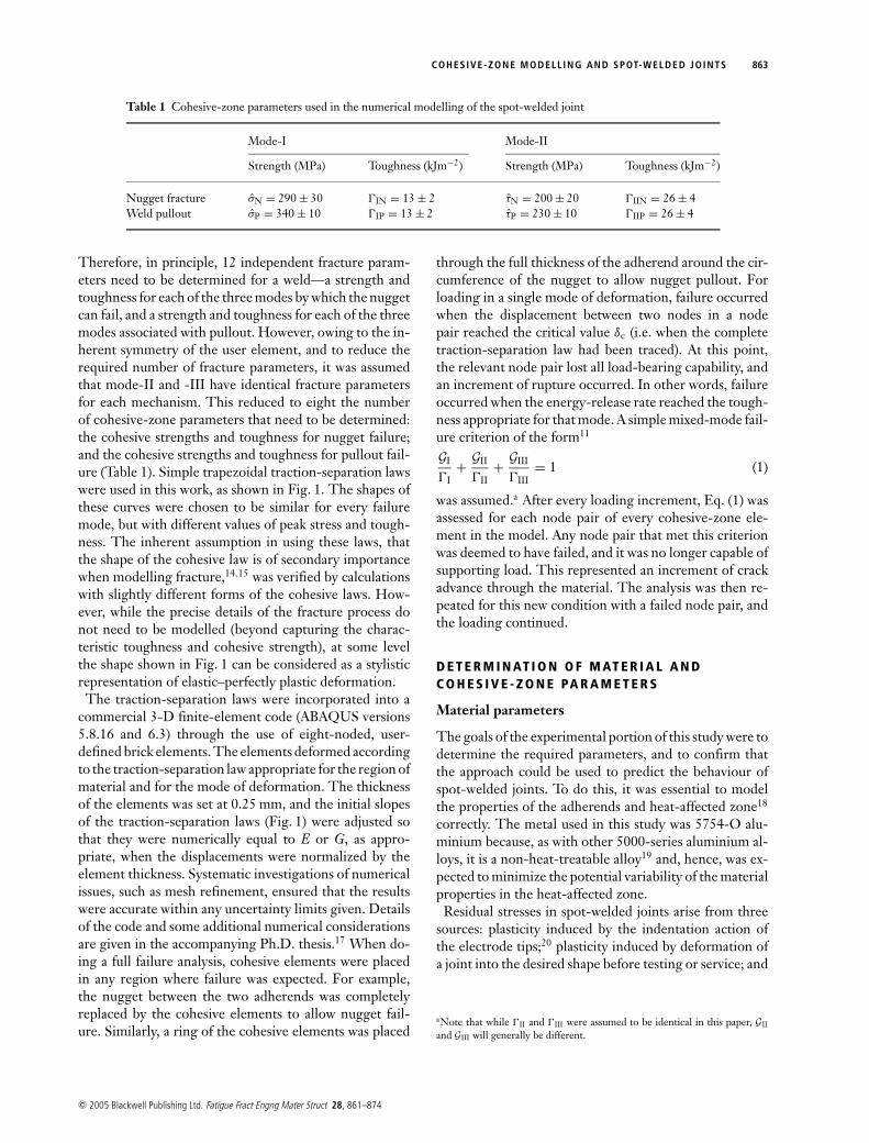
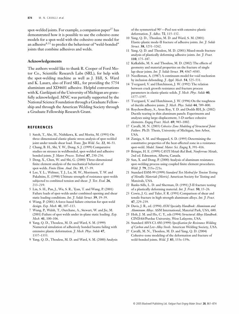
Therefore, in principle, 12 independent fracture param-eters need to be determined for a weld—a strength andtoughness for each of the three modes by which the nuggetcan fail, and a strength and toughness for each of the threemodes associated with pullout. However, owing to the in-herent symmetry of the user element, and to reduce therequired number of fracture parameters, it was assumedthat mode-II and -III have identical fracture parametersfor each mechanism. This reduced to eight the numberof cohesive-zone parameters that need to be determined:the cohesive strengths and toughness for nugget failure;and the cohesive strengths and toughness for pullout fail-ure (Table 1). Simple trapezoidal traction-separation lawswere used in this work, as shown in Fig. 1. The shapes ofthese curves were chosen to be similar for every failuremode, but with different values of peak stress and tough-ness. The inherent assumption in using these laws, thatthe shape of the cohesive law is of secondary importancewhen modelling fracture,14,15 was verified by calculationswith slightly different forms of the cohesive laws. How-ever, while the precise details of the fracture process donot need to be modelled (beyond capturing the charac-teristic toughness and cohesive strength), at some levelthe shape shown in Fig. 1 can be considered as a stylisticrepresentation of elastic–perfectly plastic deformation.
The traction-separation laws were incorporated into acommercial 3-D finite-element code (ABAQUS versions5.8.16 and 6.3) through the use of eight-noded, user-defined brick elements. The elements deformed accordingto the traction-separation law appropriate for the region ofmaterial and for the mode of deformation. The thicknessof the elements was set at 0.25 mm, and the initial slopesof the traction-separation laws (Fig. 1) were adjusted sothat they were numerically equal to E or G, as appro-priate, when the displacements were normalized by theelement thickness. Systematic investigations of numericalissues, such as mesh refinement, ensured that the resultswere accurate within any uncertainty limits given. Detailsof the code and some additional numerical considerationsare given in the accompanying Ph.D. thesis.17 When do-ing a full failure analysis, cohesive elements were placedin any region where failure was expected. For example,the nugget between the two adherends was completelyreplaced by the cohesive elements to allow nugget fail-ure. Similarly, a ring of the cohesive elements was placed
through the full thickness of the adherend around the cir-cumference of the nugget to allow nugget pullout. Forloading in a single mode of deformation, failure occurredwhen the displacement between two nodes in a nodepair reached the critical value δc (i.e. when the completetraction-separation law had been traced). At this point,the relevant node pair lost all load-bearing capability, andan increment of rupture occurred. In other words, failureoccurred when the energy-release rate reached the tough-ness appropriate for that mode. A simple mixed-mode fail-ure criterion of the form11
GI
�I+ GII
�II+ GIII
�III= 1 (1)
was assumed.a After every loading increment, Eq. (1) wasassessed for each node pair of every cohesive-zone ele-ment in the model. Any node pair that met this criterionwas deemed to have failed, and it was no longer capable ofsupporting load. This represented an increment of crackadvance through the material. The analysis was then re-peated for this new condition with a failed node pair, andthe loading continued.
D E T E R M I N AT I O N O F M AT E R I A L A N DC O H E S I V E - Z O N E PA R A M E T E R S
Material parameters
The goals of the experimental portion of this study were todetermine the required parameters, and to confirm thatthe approach could be used to predict the behaviour ofspot-welded joints. To do this, it was essential to modelthe properties of the adherends and heat-affected zone18
correctly. The metal used in this study was 5754-O alu-minium because, as with other 5000-series aluminium al-loys, it is a non-heat-treatable alloy19 and, hence, was ex-pected to minimize the potential variability of the materialproperties in the heat-affected zone.
Residual stresses in spot-welded joints arise from threesources: plasticity induced by the indentation action ofthe electrode tips;20 plasticity induced by deformation ofa joint into the desired shape before testing or service; and
aNote that while �II and �III were assumed to be identical in this paper, GII
and GIII will generally be different.
c© 2005 Blackwell Publishing Ltd. Fatigue Fract Engng Mater Struct 28, 861–874
864 M. N. CAVALL I et al.
Fig. 1 The form of the mode-I and mode-IItraction-separation laws used in this work.The mode-III curve is assumed to beidentical to the mode-II curve. Total areaunder each curve is equal to the toughnessfor the appropriate mode, �I, �II or �III.The appropriate energy-release rates, GI,GII or GIII, are defined as the areas undereach curve up to the current displacement.
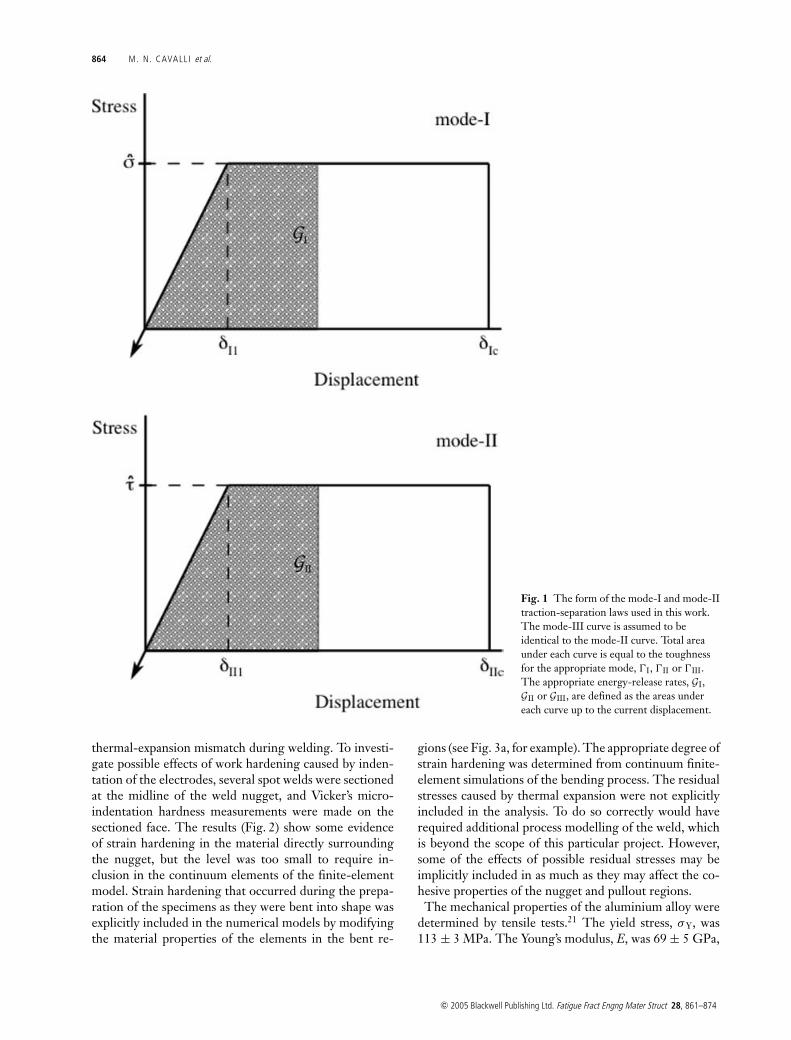
thermal-expansion mismatch during welding. To investi-gate possible effects of work hardening caused by inden-tation of the electrodes, several spot welds were sectionedat the midline of the weld nugget, and Vicker’s micro-indentation hardness measurements were made on thesectioned face. The results (Fig. 2) show some evidenceof strain hardening in the material directly surroundingthe nugget, but the level was too small to require in-clusion in the continuum elements of the finite-elementmodel. Strain hardening that occurred during the prepa-ration of the specimens as they were bent into shape wasexplicitly included in the numerical models by modifyingthe material properties of the elements in the bent re-
gions (see Fig. 3a, for example). The appropriate degree ofstrain hardening was determined from continuum finite-element simulations of the bending process. The residualstresses caused by thermal expansion were not explicitlyincluded in the analysis. To do so correctly would haverequired additional process modelling of the weld, whichis beyond the scope of this particular project. However,some of the effects of possible residual stresses may beimplicitly included in as much as they may affect the co-hesive properties of the nugget and pullout regions.
The mechanical properties of the aluminium alloy weredetermined by tensile tests.21 The yield stress, σ Y, was113 ± 3 MPa. The Young’s modulus, E, was 69 ± 5 GPa,
c© 2005 Blackwell Publishing Ltd. Fatigue Fract Engng Mater Struct 28, 861–874
COHESIVE-ZONE MODELL ING AND SPOT-WELDED JOINTS 865
0
10
20
30
40
50
60
70
80
0 2 4 6 8 10 12
Hv
(1N
,15
seco
nds)
Distance from nugget center (mm)
A
A'
weld nugget
Fig. 2 Vicker’s micro-indentation hardness as a function ofdistance from the nugget centre. This was obtained by sectioningspot-welded joints along the plane AA’, polishing the resulting facesand conducting hardness measurements along the section. At agiven distance from the weld centre, several hardnessmeasurements were taken across the adherend thickness. Theresulting average values are also shown.
and the true maximum stress was 289 ± 5 MPa. Poisson’sratio was taken to be 0.3. Post-yield data from the truestress–true strain curves of several tensile samples werefitted using the customary strain-hardening relation fortrue stress and strain of
σ = Aεn (2)
with A = 494 ± 6 MPa and n = 0.30 ± 0.01. These ma-terial properties were incorporated in the finite-elementcode to model the adherends, with further assumptions ofisotropic hardening and a von Mises yield criterion.
Specimen preparation and testing
Coach-peel and lap-shear geometries were made by join-ing aluminium sheets with a single spot-weld (Fig. 3).The spot-welding was done using a mid-frequency, direct-current, spot-welding machine with electrodes in theshape of truncated cones with tip diameters of 8 mm. Asquare current waveform was used for all samples. Al-though slightly different weld schedules were used dur-ing the course of this study, it was assumed that thesedifferences in weld schedules did not significantly affectthe fracture parameters of the welds, and that propertiesdetermined from one set of welds could, with some ac-ceptable level of approximation, be used for others. The
size of the welds did, however, depend on the processingconditions and joint geometry, so that the diameters ofthe welds were measured and explicitly modelled in thenumerical simulations. One set of coach-peel joints wasfabricated using aluminium that was 1-mm thick, with aweld current of 25 kA for either 5 or 10 cycles at 60 Hz,producing nuggets with diameters in the range of 4.5–5.5 mm. Two further sets of coach-peel joints and twosets of lap-shear joints were fabricated using aluminiumthat was 2-mm thick. One set of each type of joint wasmade with a weld current of 17 kA for 15 cycles; this re-sulted in a weld diameter in the range of 4.25–5.25 mm.The other set of each type of joint was made with a weldcurrent of 23 kA for 15 cycles; this resulted in large weldswith diameters in the range of 6.5–7.5 mm.
The coach-peel specimens were tested in a screw-drivenmachine at a displacement rate of 5 mm per minute, withdisplacements between the points of load application be-ing monitored optically using a C.C.D. camera. Failureof the 2.0-mm thick coach-peel joints always occurredwithin the nugget for the smaller set of welds, and it al-ways occurred by pullout for the larger set of welds. The1.0-mm thick coach-peel joints exhibited transitional be-haviour with failure sometimes occurring as a combina-tion of nugget fracture and pullout, and sometimes bypullout alone. The lap-shear specimens were tested in ascrew-driven machine at a displacement rate of 0.5 mmper minute. Plastic deformation in the lap-shear jointswas limited to plastic bending in the immediate regionnear the nugget. As a result, the deflections between theends of the specimens were very small, and displacementmeasurements had to be focused on the nugget region. Inparticular, the relative displacement between two pointsin the plane of the centre-line of the nugget, on the edgesof the two adherends closest to the nugget (see Fig. 3b),was measured using a C.C.D. camera. Failure of the2-mm thick lap-shear specimens always occurred bynugget fracture for both larger and smaller welds.
Cohesive-zone properties of the nugget
Because the nugget always ruptured in the 2-mm thickspecimens with the smaller welds, the coach-peel con-figuration of these specimens was used to deduce themode-I cohesive-zone parameters for the nugget, andthe lap-shear configuration was used to deduce the shearparameters.
Mode-I properties
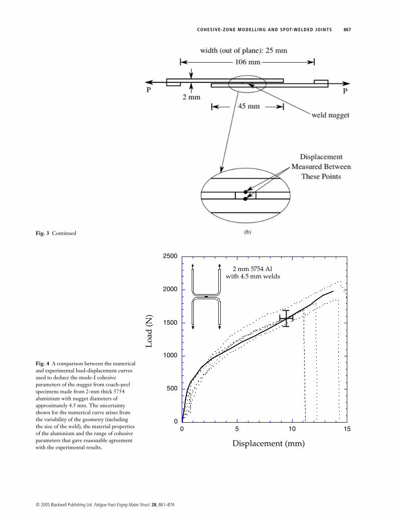
The experimental load-displacement data for the 2-mmthick coach-peel geometry with the smaller welds (failingby nugget fracture) are shown in Fig. 4 by the dashed lines.Superimposed on Fig. 4 is a solid line representing the
c© 2005 Blackwell Publishing Ltd. Fatigue Fract Engng Mater Struct 28, 861–874
866 M. N. CAVALL I et al.
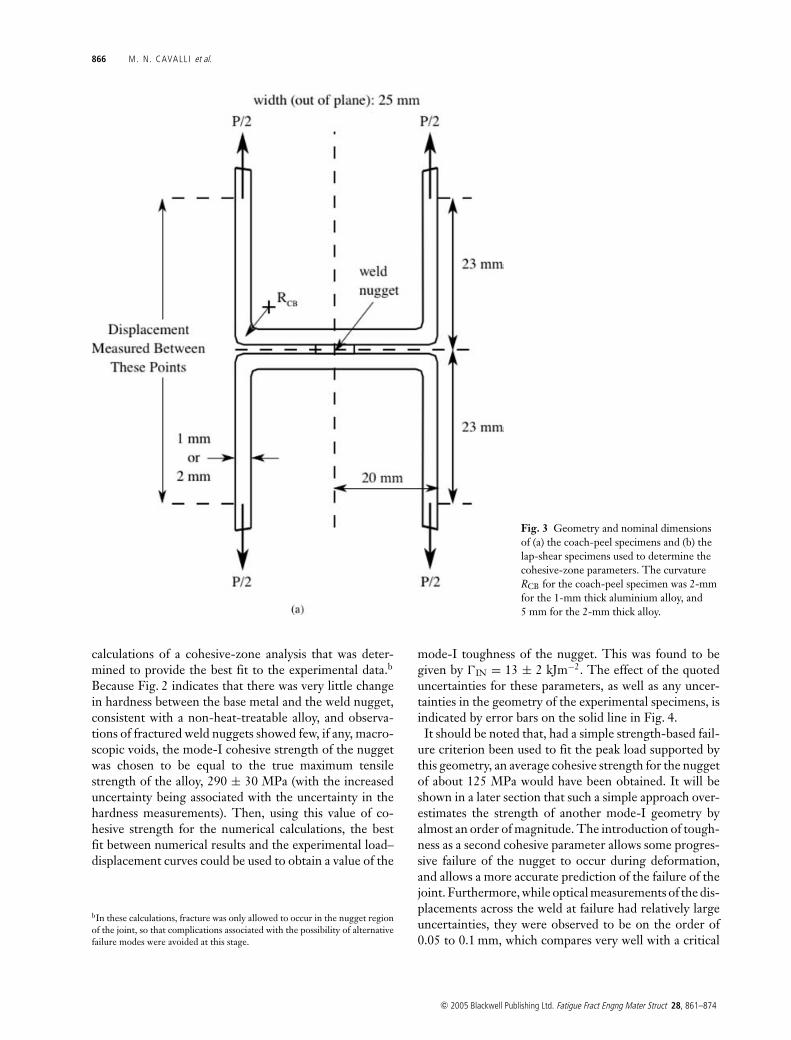
Fig. 3 Geometry and nominal dimensionsof (a) the coach-peel specimens and (b) thelap-shear specimens used to determine thecohesive-zone parameters. The curvatureRCB for the coach-peel specimen was 2-mmfor the 1-mm thick aluminium alloy, and5 mm for the 2-mm thick alloy.
calculations of a cohesive-zone analysis that was deter-mined to provide the best fit to the experimental data.b
Because Fig. 2 indicates that there was very little changein hardness between the base metal and the weld nugget,consistent with a non-heat-treatable alloy, and observa-tions of fractured weld nuggets showed few, if any, macro-scopic voids, the mode-I cohesive strength of the nuggetwas chosen to be equal to the true maximum tensilestrength of the alloy, 290 ± 30 MPa (with the increaseduncertainty being associated with the uncertainty in thehardness measurements). Then, using this value of co-hesive strength for the numerical calculations, the bestfit between numerical results and the experimental load–displacement curves could be used to obtain a value of the
bIn these calculations, fracture was only allowed to occur in the nugget regionof the joint, so that complications associated with the possibility of alternativefailure modes were avoided at this stage.
mode-I toughness of the nugget. This was found to begiven by �IN = 13 ± 2 kJm−2. The effect of the quoteduncertainties for these parameters, as well as any uncer-tainties in the geometry of the experimental specimens, isindicated by error bars on the solid line in Fig. 4.
It should be noted that, had a simple strength-based fail-ure criterion been used to fit the peak load supported bythis geometry, an average cohesive strength for the nuggetof about 125 MPa would have been obtained. It will beshown in a later section that such a simple approach over-estimates the strength of another mode-I geometry byalmost an order of magnitude. The introduction of tough-ness as a second cohesive parameter allows some progres-sive failure of the nugget to occur during deformation,and allows a more accurate prediction of the failure of thejoint. Furthermore, while optical measurements of the dis-placements across the weld at failure had relatively largeuncertainties, they were observed to be on the order of0.05 to 0.1 mm, which compares very well with a critical
c© 2005 Blackwell Publishing Ltd. Fatigue Fract Engng Mater Struct 28, 861–874
COHESIVE-ZONE MODELL ING AND SPOT-WELDED JOINTS 867
Fig. 3 Continued
0
500
1000
1500
2000
2500
0 5 10 15
Loa
d(N
)
Displacement (mm)
2 mm 5754 Alwith 4.5 mm welds
Fig. 4 A comparison between the numericaland experimental load-displacement curvesused to deduce the mode-I cohesiveparameters of the nugget from coach-peelspecimens made from 2-mm thick 5754aluminium with nugget diameters ofapproximately 4.5 mm. The uncertaintyshown for the numerical curve arises fromthe variability of the geometry (includingthe size of the weld), the material propertiesof the aluminium and the range of cohesiveparameters that gave reasonable agreementwith the experimental results.
c© 2005 Blackwell Publishing Ltd. Fatigue Fract Engng Mater Struct 28, 861–874
868 M. N. CAVALL I et al.
0
1000
2000
3000
4000
5000
6000
0 0.1 0.2 0.3 0.4 0.5 0.6 0.7 0.8
Loa
d(N
)
Displacement across weld nugget (mm)
7 mm weld
4.5 mm weld
2 mm 5754 Al
range of observed failure
range of observed failure
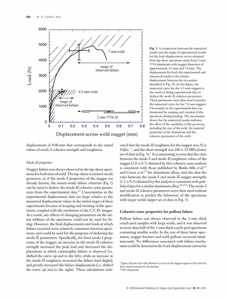
Fig. 5 A comparison between the numericalresults and the range of experimental resultsfor the load–displacement curves obtainedfrom lap-shear specimens made from 2-mm5754 aluminium with nugget diameters ofapproximately 4.5 mm and 7.0 mm. Thedisplacement for both the experimental andnumerical results is the relativedisplacement between the two pointsidentified in Fig. 3b. In this figure, thenumerical curve for the 4.5-mm nuggets isthe result of fitting experimental data todeduce the mode-II cohesive parameters.These parameters were then used to predictthe numerical curve for the 7.0 mm nuggets.Uncertainty in the experimental data wasdominated by warping and rotation of thespecimens during loading. The uncertaintyshown for the numerical results indicatesthe effect of the variability of the geometry,including the size of the weld, the materialproperties of the aluminium and thecohesive parameters of the weld.
displacement of 0.08 mm that corresponds to the statedvalues of mode-I cohesive strength and toughness.
Mode-II properties
Nugget failure was always observed in the lap-shear speci-mens for both sizes of weld. The lap-shear is a mixed-modegeometry, so if the mode-I properties of the nugget arealready known, the mixed-mode failure criterion (Eq. 2)can be used to deduce the mode-II cohesive-zone param-eters from the experimental data.12 Uncertainties in theexperimental displacement data are large relative to themeasured displacement values in the initial stages of theseexperiments because of warping and twisting of the spec-imens, coupled with the resolution of the C.C.D. images.As a result, any effects of changing parameters on the ini-tial stiffness of the specimens could not be used for fit-ting. However, the final displacements and loads at whichfailure occurred were relatively consistent between speci-mens, and could be used for the purposes of deducing themode-II parameters. Specifically, for fixed mode-I prop-erties of the nugget, an increase in the mode-II cohesivestrength increased the peak load and decreased the dis-placement at which catastrophic failure is observed (i.e.shifted the curve up and to the left), while an increase inthe mode-II toughness increased the failure load slightlyand greatly increased the failure displacement (i.e. shiftedthe curve up and to the right). These calculations indi-
cated that the mode-II toughness for the nugget was 26 ±4 kJm−2, and the shear strength was 200 ± 20 MPa (lowerset of data in Fig. 5).c It is interesting to note that the ratiobetween the mode-I and mode-II toughness values of thenugget (2.0 ± 0.7) obtained by this cohesive-zone analysisis consistent with those published by Banks-Sills et al.22
and Cowie et al.23 for aluminium alloys, and also that theratio between the mode-I and mode-II nugget strengths(1.5 ± 0.3) obtained by this analysis is consistent with pub-lished data for a similar aluminium alloy.24,25d The mode-Iand mode-II cohesive parameters were then used withoutmodification to predict the behaviour of the specimenswith larger welds (upper set of data in Fig. 5).
Cohesive-zone properties for pullout failure
Pullout failure was always observed in the 2-mm thickcoach-peel samples with large welds, and it was observedin more than half of the 1-mm thick coach-peel specimenscontaining smaller welds. In the rest of these latter spec-imens, nugget fracture and weld pullout occurred simul-taneously. No differences associated with failure mecha-nism could be detected in the load-displacement curves for
cAgain, fracture was only allowed to occur in the nugget region of the joint forthese initial numerical calculations.d5454 aluminum.
c© 2005 Blackwell Publishing Ltd. Fatigue Fract Engng Mater Struct 28, 861–874
COHESIVE-ZONE MODELL ING AND SPOT-WELDED JOINTS 869
these specimens, nor was there any correlation with theprecise nugget size. Clearly, the range of material proper-ties was such that this geometry exhibited a transition inthe failure mechanism; this was subsequently confirmedwhen all the cohesive parameters had been determined.
Characterization of the cohesive parameters for pulloutwas complicated because the mode mixedness is a functionof location around the nugget. This precluded isolation ofthe normal and shear properties, as was done for nuggetfailure. As a result, it was not possible to use a single ge-ometry to determine one set of pullout parameters andanother geometry to determine the other. The cohesiveparameters had to be deduced by simultaneously investi-gating at least two geometries that exhibited pullout fail-ure. This was done by using experimental data for the2-mm coach-peel specimens with a weld size of 7.0 mm,and the 1-mm coach-peel specimens for which only pull-out occurred. Two numerical models of each geometrywere programmed, one which allowed only pullout fail-ure, using continuum elements for the weld nugget and asecond which allowed pullout failure and nugget fracture,using the mode-I properties for nugget fracture deter-mined previously.
Owing to the geometrical differences between the1-mm and 2-mm coach peel joints, the relative portionsof bending and shearing stresses in the material which
0
500
1000
1500
2000
2500
0 5 10 15 20 25 30 35
Loa
d(N
)
Displacement (mm)
2 mm Al7 mm weld
1 mm Al5 mm weld
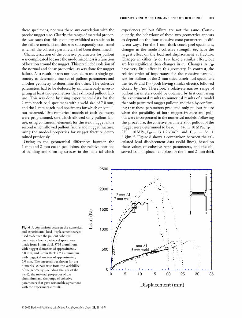
Fig. 6 A comparison between the numericaland experimental load–displacement curvesused to deduce the pullout cohesiveparameters from coach-peel specimensmade from 1-mm thick 5754 aluminiumwith nugget diameters of approximately5.0 mm, and 2-mm thick 5754 aluminiumwith nugget diameters of approximately7.0 mm. The uncertainties shown for thenumerical curves arise from the variabilityof the geometry (including the size of theweld), the material properties of thealuminium and the range of cohesiveparameters that gave reasonable agreementwith the experimental results.
experiences pullout failure are not the same. Conse-quently, the behaviour of these two geometries appearsto depend on the four cohesive-zone parameters in dif-ferent ways. For the 1-mm thick coach-peel specimens,changes in the mode I cohesive strength, σ̂P, have thelargest effect on the load and displacement at fracture.Changes in either τ̂P or �IIP have a similar effect, butare less significant than changes in σ̂P. Changes in �IP
have very little effect in this geometry. In contrast, therelative order of importance for the cohesive parame-ters for pullout in the 2-mm thick coach-peel specimenswas τ̂P, σ̂P and �IP (both having similar effects), followedclosely by �IIP. Therefore, a relatively narrow range ofpullout parameters could be obtained by first comparingthe experimental results to numerical results of a modelthat only permitted nugget pullout, and then by confirm-ing that these parameters predicted only pullout failurewhen the possibility of both nugget fracture and pull-out were incorporated in the numerical models Followingthis procedure, the cohesive parameters for pullout of thenugget were determined to be σ̂P = 340 ± 10 MPa, τ̂P =230 ± 10 MPa, �IP = 13 ± 2 kJm−2 and �IIP = 26 ±4 kJm−2. Figure 6 shows a comparison between the cal-culated load–displacement data (solid lines), based onthese values of cohesive-zone parameters, and the ob-served load–displacement plots for the 1- and 2-mm thick
c© 2005 Blackwell Publishing Ltd. Fatigue Fract Engng Mater Struct 28, 861–874
870 M. N. CAVALL I et al.
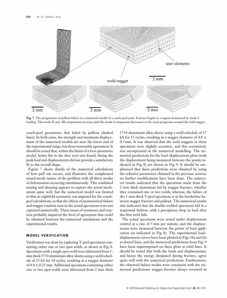
Fig. 7 The progression of pullout failure in a numerical model of a coach-peel joint. Fracture begins in a region dominated by mode-Iloading. The mode-II and -III components increase (and the mode-I component decreases) as the crack progresses around the weld nugget.
coach-peel geometries that failed by pullout (dashedlines). In both cases, the strength and maximum displace-ment of the numerical models are near the lower end ofthe experimental range, but show reasonable agreement. Itshould be noted that, within the limits of a four-parametermodel, better fits to the data were not found; fitting thepeak load and displacements did not provide a satisfactoryfit to the overall shape.
Figure 7 shows details of the numerical calculationsof how pull out occurs, and illustrates the complicatedmixed-mode nature of the problem with all three modesof deformation occurring simultaneously. This combinedtearing and shearing appears to capture the actual mech-anism quite well, but the numerical model was limitedin that an eightfold symmetry was imposed for the coach-peel calculations, so that the effects of asymmetrical failureand nugget rotation seen in the actual specimens were notcaptured numerically. These issues of symmetry and rota-tion probably impaired the level of agreement that couldbe obtained between the numerical simulations and theexperimental results.
M O D E L V E R I F I C AT I O N
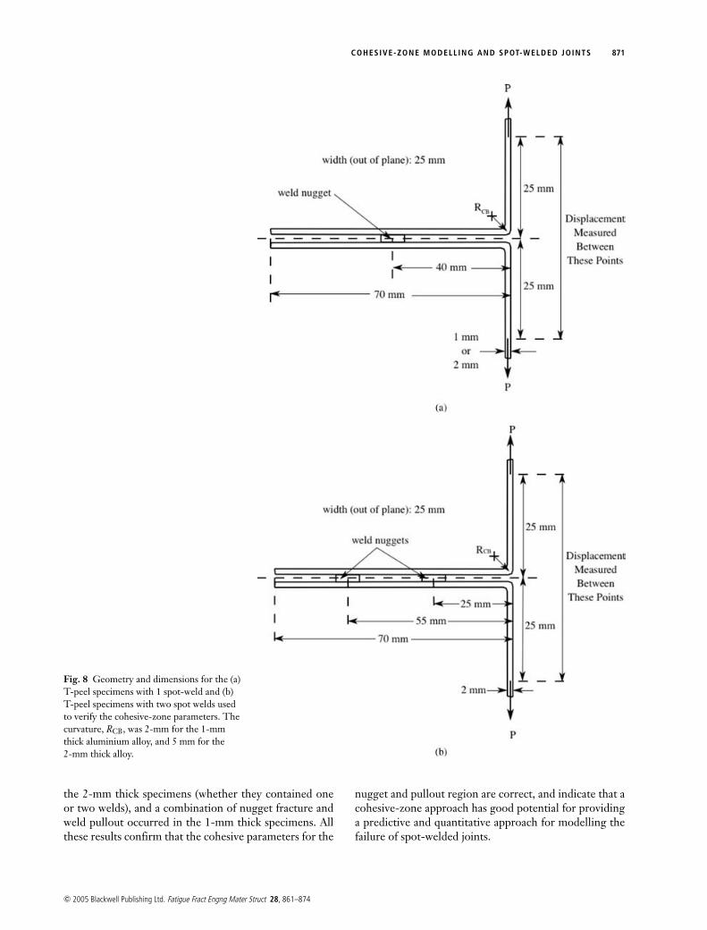
Verification was done by exploring T-peel specimens con-taining either one or two spot welds, as shown in Fig. 8.Specimens with a single spot-weld were fabricated from 1-mm thick 5754 aluminium alloy sheets using a weld sched-ule of 25 kA for 10 cycles, resulting in a nugget diameterof 4.0 ± 0.25 mm. Additional specimens containing eitherone or two spot welds were fabricated from 2-mm thick
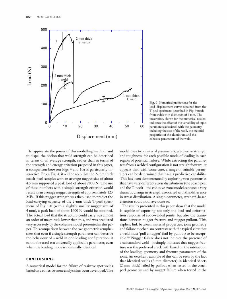
5754 aluminium alloy sheets using a weld schedule of 17kA for 15 cycles, resulting in a nugget diameter of 4.0 ±0.5 mm. It was observed that the weld nuggets in thesespecimens were slightly eccentric, and this eccentricitywas incorporated in the numerical modelling. The nu-merical predictions for the load–displacement plots (withthe displacement being measured between the points in-dicated in Fig. 8) are shown in Fig. 9. It should be em-phasized that these predictions were obtained by usingthe cohesive parameters obtained in the previous section;no further modifications have been done. The numeri-cal results indicated that the specimens made from the2-mm thick aluminium fail by nugget fracture, whetherthey contained one or two welds; whereas, the failure ofthe 1-mm thick T-peel specimens is at the borderline be-tween nugget fracture and pullout. The numerical resultsalso indicated that the double-welded specimens fail in asequential fashion, with a precipitous drop in load afterthe first weld fails.
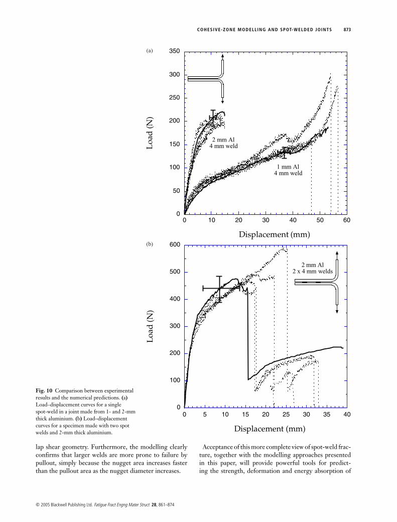
The actual specimens were tested under displacementcontrol at a rate of 5 mm per minute, and the displace-ments were measured between the points of load appli-cation (as indicated in Fig. 8). The experimental load–displacement curves have been plotted in Figs 10a and (b)as dotted lines, and the numerical predictions from Fig. 9have been superimposed on these plots as solid lines. Itshould be noted that both the loads and displacements,and hence the energy dissipated during fracture, agreequite well with the numerical predictions. Furthermore,the observed failure modes were consistent with the nu-merical predictions: nugget fracture always occurred in
c© 2005 Blackwell Publishing Ltd. Fatigue Fract Engng Mater Struct 28, 861–874
COHESIVE-ZONE MODELL ING AND SPOT-WELDED JOINTS 871
Fig. 8 Geometry and dimensions for the (a)T-peel specimens with 1 spot-weld and (b)T-peel specimens with two spot welds usedto verify the cohesive-zone parameters. Thecurvature, RCB, was 2-mm for the 1-mmthick aluminium alloy, and 5 mm for the2-mm thick alloy.
the 2-mm thick specimens (whether they contained oneor two welds), and a combination of nugget fracture andweld pullout occurred in the 1-mm thick specimens. Allthese results confirm that the cohesive parameters for the
nugget and pullout region are correct, and indicate that acohesive-zone approach has good potential for providinga predictive and quantitative approach for modelling thefailure of spot-welded joints.
c© 2005 Blackwell Publishing Ltd. Fatigue Fract Engng Mater Struct 28, 861–874
872 M. N. CAVALL I et al.
0
100
200
300
400
500
0 10 20 30 40 50 60
Loa
d(N
)
Displacement (mm)
1 mm thick1 weld
2 mm thick1 weld
2 mm thick2 welds
Fig. 9 Numerical predictions for theload–displacement curves obtained from theT-peel specimens described in Fig. 9 madefrom welds with diameters of 4 mm. Theuncertainty shown for the numerical resultsindicates the effect of the variability of inputparameters associated with the geometry,including the size of the weld, the materialproperties of the aluminium and thecohesive parameters of the weld.
To appreciate the power of this modelling method, andto dispel the notion that weld strength can be describedin terms of an average strength, rather than in terms ofthe strength and energy criterion proposed in this paper,a comparison between Figs 4 and 10a is particularly in-structive. From Fig. 4, it will be seen that the 2-mm thickcoach-peel samples with an average nugget size of about4.5 mm supported a peak load of about 2000 N. The useof these numbers with a simple strength criterion wouldresult in an average nugget strength of approximately 125MPa. If this nugget strength was then used to predict theload-carrying capacity of the 2-mm thick T-peel speci-mens of Fig. 10a (with a slightly smaller nugget size of4 mm), a peak load of about 1600 N would be obtained.The actual load that the structure could carry was almostan order of magnitude lower than this, and was predictedvery accurately by the cohesive model presented in this pa-per. This comparison between the two geometries empha-sizes that even if a single strength parameter can describethe behaviour of a weld in one loading configuration, itcannot be used as a universally applicable parameter, evenwhen the loading mode is nominally identical.
C O N C L U S I O N S
A numerical model for the failure of resistive spot weldsbased on a cohesive-zone analysis has been developed. The
model uses two material parameters, a cohesive strengthand toughness, for each possible mode of loading in eachregion of potential failure. While extracting the parame-ters from a welded configuration is not straightforward, itappears that, with some care, a range of suitable param-eters can be determined that have a predictive capability.This has been demonstrated by exploring two geometriesthat have very different stress distributions (the coach peeland the T-peel)—the cohesive-zone model captures a verydramatic change in strength associated with this differencein stress distribution. A single-parameter, strength-basedcriterion could not have done so.
The results presented in this paper show that the modelis capable of capturing not only the load and deforma-tion response of spot-welded joints, but also the transi-tions between nugget fracture and nugget pullout. Thisexplicit link between material properties, joint geometryand failure mechanism contrasts with the typical view thata weld must ‘pull a nugget’ (fail by pullout) to be accept-able.26 Nugget failure does not indicate the presence ofa substandard weld—it simply indicates that nugget frac-ture was the preferred crack path based on the interactionof the loading, geometry and fracture parameters of thejoint. An excellent example of this can be seen by the factthat identical welds (7-mm diameter) in identical sheets(2-mm thick) failed by pullout when tested in the coachpeel geometry and by nugget failure when tested in the
c© 2005 Blackwell Publishing Ltd. Fatigue Fract Engng Mater Struct 28, 861–874
COHESIVE-ZONE MODELL ING AND SPOT-WELDED JOINTS 873
0
50
100
150
200
250
300
350
0 10 20 30 40 50 60
Loa
d(N
)
Displacement (mm)
2 mm Al4 mm weld
1 mm Al4 mm weld
(a)
0
100
200
300
400
500
600
0 5 10 15 20 25 30 35 40
Load
(N)
Displacement (mm)
2 mm Al2 x 4 mm welds
(b)
Fig. 10 Comparison between experimentalresults and the numerical predictions. (a)Load–displacement curves for a singlespot-weld in a joint made from 1- and 2-mmthick aluminium. (b) Load–displacementcurves for a specimen made with two spotwelds and 2-mm thick aluminium.
lap shear geometry. Furthermore, the modelling clearlyconfirms that larger welds are more prone to failure bypullout, simply because the nugget area increases fasterthan the pullout area as the nugget diameter increases.
Acceptance of this more complete view of spot-weld frac-ture, together with the modelling approaches presentedin this paper, will provide powerful tools for predict-ing the strength, deformation and energy absorption of
c© 2005 Blackwell Publishing Ltd. Fatigue Fract Engng Mater Struct 28, 861–874
874 M. N. CAVALL I et al.
spot-welded joints. For example, a companion paper27 hasdemonstrated how it is possible to use the cohesive-zonemodels for a spot-weld with the cohesive-zone model foran adhesive8,11 to predict the behaviour of “weld-bonded”joints that combine adhesives and welds.
Acknowledgements
The authors would like to thank R. Cooper of Ford Mo-tor Co., Scientific Research Labs (SRL), for help withthe spot-welding machine as well as J. Hill, S. Wardand K. Lasarz, also of Ford SRL, for providing the 5754aluminium and XD4601 adhesive. Helpful conversationswith K. Garikipati of the University of Michigan are grate-fully acknowledged. MNC was partially supported by theNational Science Foundation through a Graduate Fellow-ship and through the American Welding Society througha Graduate Fellowship Research Grant.
R E F E R E N C E S
1 Satoh, T., Abe, H., Nishikawa, K. and Morita, M. (1991) Onthree-dimensional elastic-plastic stress analysis of spot-weldedjoint under tensile shear load. Trans. Jpn Weld. Soc. 22, 46–51.
2 Chang, B. H., Shi, Y. W., Dong, S. J. (1999) Comparativestudies on stresses in weldbonded, spot-welded and adhesivebonded joints. J. Mater. Process. Technol. 87, 230–236.
3 Deng, X., Chen, W. and Shi, G. (2000) Three-dimensionalfinite element analysis of the mechanical behavior ofspot-welds. Finite Elem. Anal. Des. 35, 17–39.
4 Lee, Y. L., Wehner, T. J., Lu, M. W., Morrissett, T. W. andPakalnins, E. (1998) Ultimate strength of resistance spot-weldssubjected to combined tension and shear. J. Test. Eval. 26,213–219.
5 Lin, S. H., Pan, J., Wu, S. R., Tyan, T. and Wung, P. (2001)Failure loads of spot-welds under combined opening and shearstatic loading conditions. Int. J. Solids Struct. 39, 19–39.
6 Wung, P. (2001) A force-based failure criterion for spot-welddesign. Exp. Mech. 41, 107–113.
7 Wung, P., Walsh, T., Ourchane, A., Stewart, W. and Jie, M.(2001) Failure of spot welds under in-plane static loading. Exp.Mech. 41, 100–106.
8 Yang, Q. D., Thouless, M. D. and Ward, S. M. (1999)Numerical simulation of adhesively bonded beams failing withextensive plastic deformation. J. Mech. Phys. Solids 47,1337–1353.
9 Yang, Q. D., Thouless, M. D. and Ward, S. M. (2000) Analysis
of the symmetrical 90◦—Peel test with extensive plasticdeformation. J. Adhes. 72, 115–132.
10 Yang, Q. D., Thouless, M. D. and Ward, S. M. (2001)Elastic-plastic mode-II fracture of adhesive joints. Int. J. SolidsStruct. 38, 3251–3262.
11 Yang, Q. D. and Thouless, M. D. (2001) Mixed-mode fractureanalysis of plastically deforming adhesive joints. Int. J. Fract.110, 175–187.
12 Kafkalidis, M. S. and Thouless, M. D. (2002) The effects ofgeometry and material properties on the fracture of singlelap-shear joints. Int. J. Solids Struct. 39, 4367–4383.
13 Needleman, A. (1987) A continuum model for void nucleationby inclusion debonding. J. Appl. Mech. 54, 525–531.
14 Tvergaard, V. and Hutchinson, J. W. (1992) The relationbetween crack growth resistance and fracture processparameters in elastic-plastic solids. J. Mech. Phys. Solids 40,1377–1397.
15 Tvergaard, V. and Hutchinson, J. W. (1996) On the toughnessof ductile adhesive joints. J. Mech. Phys. Solids 44, 789–800.
16 Roychowdhury, S., Arun Roy, Y. D. and Dodds RH, Jr. (2002)Ductile tearing in thin aluminum panels: Experiments andanalyses using large-displacement, 3-D surface cohesiveelements. Engng Fract. Mech. 69, 983–1002.
17 Cavalli, M. N. (2003) Cohesive Zone Modeling of Structural JointFailure. Ph.D. Thesis, University of Michigan, Ann Arbor,USA.
18 Zuniga, S. M. and Sheppard, S. D. (1995) Determining theconstitutive properties of the heat-affected zone in a resistancespot-weld. Model. Simul. Mater. Sci. Engng 3, 391–416.
19 Bringas, H. E. (1999) CASTI Metals Red Book, Nonferrous Metals,2nd ed. Edmonton, Alberta, Canada.
20 Sun, X. and Dong, P. (2000) Analysis of aluminum resistancespot-welding process using coupled finite element procedures.Weld. J. 79, 215s–221s.
21 Standard E8M-99 (1999) Standard Test Method for Tension Testingof Metallic Materials [Metric]. American Society for Testing andMateirals, USA.
22 Banks-Sills, L. D. and Sherman, D. (1991) J-II fracture testingof a plastically deforming material. Int. J. Fract. 50, 15–26.
23 Cowie, J. G. and Tuler, F. R. (1991) Comparison of shear andtensile fracture in high strength aluminum alloys. Int. J. Fract.47, 229–239.
24 Davis, J. R., ed. (1994) ASM Specialty Handbook: Aluminum andAluminum Alloys. ASM International, Material Park, USA, 680.
25 Holt, J. M. and Ho, C. Y., eds (1994) Structural Alloys Handbook.CINDAS/Purdue University, West Lafayette, USA.
26 Standard AWS C1.4M (1999) Specification for Resistance Weldingof Carbon and Low-Alloy Steels. American Welding Society, USA.
27 Cavalli, M. N., Thouless, M. D. and Yang, Q. D. (2004)Cohesive-zone modeling of the deformation and fracture ofweld-bonded joints. Weld. J. 83, 133s–139s.
c© 2005 Blackwell Publishing Ltd. Fatigue Fract Engng Mater Struct 28, 861–874


![Deformation and Fracture Mechanics of Engineering Material [RichardW.hertzberg]](https://img.pdfslide.us/doc/110x75/5695d03c1a28ab9b029195f8/deformation-and-fracture-mechanics-of-engineering-material-richardwhertzberg.jpg)