Embed Size (px)
DESCRIPTION
COE 405 Logic Design with Behavioral Models of Combinational & Sequential Logic. Dr. Aiman H. El-Maleh Computer Engineering Department King Fahd University of Petroleum & Minerals. Outline. Behavioral Modeling Data Types for Behavioral Modeling - PowerPoint PPT Presentation
Citation preview

COE 405COE 405 Logic Design with Behavioral Logic Design with Behavioral
Models of Combinational & Models of Combinational & Sequential LogicSequential Logic
COE 405COE 405 Logic Design with Behavioral Logic Design with Behavioral
Models of Combinational & Models of Combinational & Sequential LogicSequential Logic
Dr. Aiman H. El-Maleh
Computer Engineering Department
King Fahd University of Petroleum & Minerals
Dr. Aiman H. El-Maleh
Computer Engineering Department
King Fahd University of Petroleum & Minerals

1-2
OutlineOutlineOutlineOutline
Behavioral Modeling Data Types for Behavioral Modeling Boolean Equation-Based Behavioral Models of
Combinational Logic Assign Statement Verilog Operators Propagation Delay & Continuous Assignment Latches & Level-Sensitive Circuits Always Block, Procedural Assignment If and Case Statements
Behavioral Modeling Data Types for Behavioral Modeling Boolean Equation-Based Behavioral Models of
Combinational Logic Assign Statement Verilog Operators Propagation Delay & Continuous Assignment Latches & Level-Sensitive Circuits Always Block, Procedural Assignment If and Case Statements

1-3
OutlineOutlineOutlineOutline
Data Flow / Register Transfer Level (RTL) Algorithm-Based Models Repetitive Algorithms Tasks and Functions Behavioral Modeling of Control Unit Behavioral Models of Counters Behavioral Models of Registers
Data Flow / Register Transfer Level (RTL) Algorithm-Based Models Repetitive Algorithms Tasks and Functions Behavioral Modeling of Control Unit Behavioral Models of Counters Behavioral Models of Registers

1-4
Behavioral ModelingBehavioral ModelingBehavioral ModelingBehavioral Modeling
Behavioral modeling describes the functionality of a design • What the design will do
• Not how the design will be built in hardware
Behavioral models specify the input-output model of a logic circuit and suppress details about its low level internal structure
Behavioral modeling encourages designers to• Rapidly create a behavioral prototype of a design
• Verify its functionality
• Use synthesis tool to optimize and map design into a given technology

1-5
Data Types for Behavioral ModelingData Types for Behavioral ModelingData Types for Behavioral ModelingData Types for Behavioral Modeling
All variables in Verilog have a predefined type There are two families of data types: nets and registers Net variables act like wires in physical circuit and
establish connectivity between design objects Net types include: wire, tri, wand, wor, triand, trior,
supply0, supply1, tri0, tri1, trireg Register variables act like variables in ordinary
procedural languages – they store information while the program executes
Register types include: reg, integer, real, realtime, time.

1-6
Data Types for Behavioral ModelingData Types for Behavioral ModelingData Types for Behavioral ModelingData Types for Behavioral Modeling
For synthesis, we use mainly the data types wire, reg and integer.
A wire and a reg have a default size of 1 bit. Size of integer is the size of word length in a computer,
at least 32. A reg variable may never be the output of a primitive
gate, an input or inout port of a module or the target of continuous assignment.

1-7
Boolean Equation-Based Behavioral Boolean Equation-Based Behavioral Models of Combinational LogicModels of Combinational LogicBoolean Equation-Based Behavioral Boolean Equation-Based Behavioral Models of Combinational LogicModels of Combinational Logic A Boolean equation describes combinational logic by
an expression of operations on variables. In Verilog, this is done by continuous assignment
statement. Example:
module AOI_5_CA0 (
input x_in1, x_in2, x_in3, x_in4, x_in5,
output y_out
);
assign y_out = !((x_in1 && x_in2) || (x_in3 && x_in4 && x_in5));
endmodule
A Boolean equation describes combinational logic by an expression of operations on variables.
In Verilog, this is done by continuous assignment statement.
Example:
module AOI_5_CA0 (
input x_in1, x_in2, x_in3, x_in4, x_in5,
output y_out
);
assign y_out = !((x_in1 && x_in2) || (x_in3 && x_in4 && x_in5));
endmodule

1-8
Assign StatementAssign StatementAssign StatementAssign Statement
The keyword assign declares a continuous assignment It associate the Boolean expression on the RHS with
the variable on the LHS The assignment is sensitive to the variables in the RHS Any time an event occurs on any of the variables on
the RHS, the RHS expression is revaluated and the result is used to update the LHS
A continuous assignment is said to describe implicit combinational logic

1-9
Assign StatementAssign StatementAssign StatementAssign Statement
module AOI_5_CA1 ( input x_in1, x_in2, x_in3, x_in4, x_in5, enable,output y_out
);assign y_out = enable ? !((x_in1 && x_in2) || (x_in3 && x_in4 && x_in5)) : 1’bz;endmodule

1-10
Assign StatementAssign StatementAssign StatementAssign Statement
The conditional operator (?:) acts like a software if-then-else switch that selects between two expressions.
If the value of enable is true, the expression to the right of the ? Is evaluated and used to assign value to y_out
Otherwise, the expression to the right of the : is used. Using 1’bz illustrates how to write models that include
three-state outputs. A module may contain multiple continuous
assignments; the assignments are active concurrently with all other continuous assignments, primitives, behavioral statements, and instantiated modules.

1-11
Assign StatementAssign StatementAssign StatementAssign Statement
module Mux_2_32_CA #(parameter word_size=32)( output [wordsize-1:0] mux_out,
input [wordsize-1:0] data_1, data_0,input select
);assign mux_out = select? data_1 : data_0;endmodule

1-12
Verilog OperatorsVerilog OperatorsVerilog OperatorsVerilog Operators
{ } concatenation
+ - * / ** arithmetic
% modulus
> >= < <= relational
! logical NOT
&& logical AND
|| logical OR
== logical equality
!= logical inequality
=== case equality
!== case inequality
? : conditional
~ bit-wise NOT
& bit-wise AND
| bit-wise OR
^ bit-wise XOR
^~ ~^ bit-wise XNOR
& reduction AND
| reduction OR
~& reduction NAND
~| reduction NOR
^ reduction XOR
~^ ^~ reduction XNOR
<< shift left
>> shift right
1-13
Verilog OperatorsVerilog OperatorsVerilog OperatorsVerilog Operators
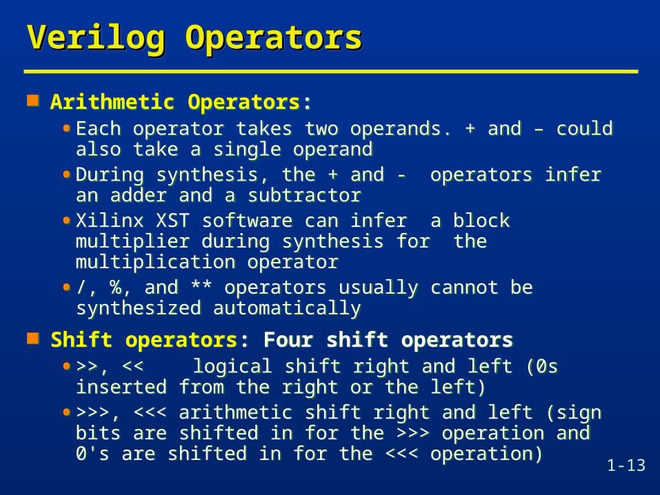
Arithmetic Operators:• Each operator takes two operands. + and – could also take a
single operand
• During synthesis, the + and - operators infer an adder and a subtractor
• Xilinx XST software can infer a block multiplier during synthesis for the multiplication operator
• /, %, and ** operators usually cannot be synthesized automatically
Shift operators: Four shift operators• >>, << logical shift right and left (0s inserted from the
right or the left)
• >>>, <<< arithmetic shift right and left (sign bits are shifted in for the >>> operation and 0's are shifted in for the <<< operation)

1-14
Verilog OperatorsVerilog OperatorsVerilog OperatorsVerilog Operators
• If both operands of a shift operator are signals, as in a << b, the operator infers a barrel shifter, a fairly complex circuit
• If the shifted amount is fixed, as in a << 2, the operation infers no logic and involves only routing of the input signals (can also be done with {} operator)
Examples of shift operations:

1-15
Verilog OperatorsVerilog OperatorsVerilog OperatorsVerilog Operators
Relational and equality operators:• compare two operands and return a 1-bit logical (Boolean)
value: either 0 or 1
• 4 relational operators: >, <, <=, and >=
• 4 equality operators: ==, ! =, ===, and ! ==
• Case equality and case inequality operators, take the x and z bits in the operands into consideration in the match cannot be synthesized.
• The relational operators and the == and ! = operators infer comparators during synthesis
1-16
Verilog OperatorsVerilog OperatorsVerilog OperatorsVerilog Operators
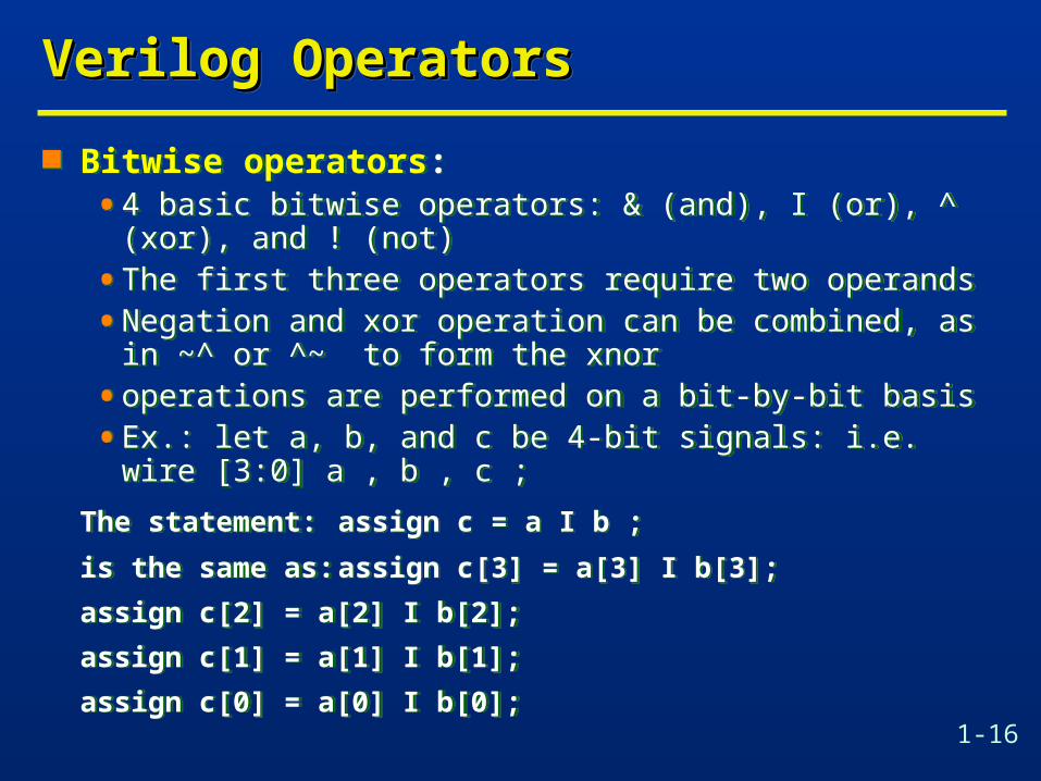
Bitwise operators:• 4 basic bitwise operators: & (and), I (or), ^ (xor), and ! (not)
• The first three operators require two operands
• Negation and xor operation can be combined, as in ~^ or ^~ to form the xnor
• operations are performed on a bit-by-bit basis
• Ex.: let a, b, and c be 4-bit signals: i.e. wire [3:0] a , b , c ;
The statement: assign c = a I b ;
is the same as: assign c[3] = a[3] I b[3];
assign c[2] = a[2] I b[2];
assign c[1] = a[1] I b[1];
assign c[0] = a[0] I b[0];

1-17
Verilog OperatorsVerilog OperatorsVerilog OperatorsVerilog Operators
Reduction operators: &, I , and ^ operators may have only one operand and then are known as reduction operators.• The single operand usually has an array data type.
• The designated operation is performed on all elements of the array and returns a I-bit result.
• For example, let a be a 4-bit signal and y be a 1-bit signal:
wire [3:0] a ; wire y ;
The statement: assign y = I a ; // only one operand
is the same as: assign y = a[3] | a[2] | a[1] | a[0] ;
1-18
Verilog OperatorsVerilog OperatorsVerilog OperatorsVerilog Operators
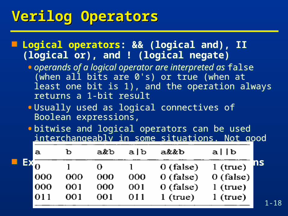
Logical operators: && (logical and), II (logical or), and ! (logical negate)• operands of a logical operator are interpreted as false (when
all bits are 0's) or true (when at least one bit is 1), and the operation always returns a 1-bit result
• Usually used as logical connectives of Boolean expressions,
• bitwise and logical operators can be used interchangeably in some situations. Not good practice though!
Examples of bitwise and logical operations

1-19
Verilog OperatorsVerilog OperatorsVerilog OperatorsVerilog Operators
Conditional operator: ? : takes three operands and its general format is
[signal] = [boolean-exp] ? [true-exp] : [false-exp];• The [boolean-expl] is a Boolean expression that returns true
(1’b1) or false ( 1'b0).
• Ex.: assign max = (a>b) ? a : b; //max will get the maximum of the signals a and b
• The operator can be thought as a simplified if-then-else statement. Infers a mux
• Can be cascaded or nested:
assign max = (a>b) ? ((a>c) ? a : c) : ((b>c) ? b : c ) ; // max of three ignals

1-20
Verilog OperatorsVerilog OperatorsVerilog OperatorsVerilog Operators
Concatenation and replication operators: { } and {{ }} { } combines segments of elements and small arrays to
form a large array:
wire a1; wire [3:0] a4; wire [7:0] b8, c8, d8;
assign b8 = {a4 , a4} ;
assign c8 = {a1, a1, a4, 2'b00 } ;
assign d8 = {b8[3:0] , c8[3:0]} ; Concatenation operator involves reconnection of the
input and output signals and only requires "wiring”. Can be used for shifting or rotating data

1-21
Verilog OperatorsVerilog OperatorsVerilog OperatorsVerilog Operators
wire [7:0] a, rot, shl , sha;
assign rot = {a[2:0], a[7:3]) ; // Rotate a to right 3 bits
assign shl = {3'b000, a[7:3]) ; // shift a to right 3 bits and insert 0s (logical shift)
assign sha = {a[78] , a[7] , a[7] , a[7:3]} ; // arithmetic shift a to right 3 bits
The replication operator, N{ }, replicates the enclosed string. The replication constant, N, specifies the number of replications. For example:
{4{2 'b01}} returns 8' b01010101.

1-22
Full AdderFull AdderFull AdderFull Adder
module fadd (output Cout, S, input A, B, Cin);
assign S = A ^(B ^ Cin);
assign Cout = (A & B)
| (A & Cin)
| (B & Cin) ;
endmodule
module fadd (output Cout, S, input A, B, Cin);
assign S = A ^(B ^ Cin);
assign Cout = (A & B)
| (A & Cin)
| (B & Cin) ;
endmoduleA
B
Cin
Cout
S

1-23
Behavioral Description of an AdderBehavioral Description of an AdderBehavioral Description of an AdderBehavioral Description of an Adder
module adder #(parameter width = 4)
(output cout, output [width-1:0] sum,
input [width-1:0] a, b, input cin);
assign {cout, sum} = a + b + cin;
// note: Verilog treats wires as ‘unsigned’ numbers
endmodule
module adder #(parameter width = 4)
(output cout, output [width-1:0] sum,
input [width-1:0] a, b, input cin);
assign {cout, sum} = a + b + cin;
// note: Verilog treats wires as ‘unsigned’ numbers
endmodule { Cout, S } is a 5 bit bus:
Cout S[3] S[2] S[1] S[0]
4-bit operands,5-bit result

1-24
Propagation Delay & Continuous Propagation Delay & Continuous AssignmentAssignmentPropagation Delay & Continuous Propagation Delay & Continuous AssignmentAssignment Propagation delay can be associated with a continuous
assignment so that its implicit logic has same functionality and timing characteristics as its gate level implementation.
Propagation delay can be associated with a continuous assignment so that its implicit logic has same functionality and timing characteristics as its gate level implementation.
module fadd (output Cout, S, input A, B, Cin);wire #10 S = A ^(B ^ Cin);
wire #10 Cout = (A & B) | (A & Cin) | (B & Cin) ; endmodule

1-25
Latches & Level-Sensitive CircuitsLatches & Level-Sensitive CircuitsLatches & Level-Sensitive CircuitsLatches & Level-Sensitive Circuits
Latch can be modeled as:module latch (output q, qb, input set, reset);
assign q = ~(set & qb);assign qb = ~(reset & q);
endmodule
Synthesis tools do not accommodate this form of feedback
Latch is inferred by synthesis tools as follows:module dlatch (output q, input data_in, enable);
assign q = enable ? data_in : q;endmodulemodule dlatch2 (output q, input data_in, enable, reset);
assign q = (reset==1'b0)? 0: enable ? data_in : q;endmodule

1-26
Always BlockAlways BlockAlways BlockAlways Block
always blocks are procedural blocks that contain sequential statements.
Syntaxalways @(sensitivity list) begin
……….end
sensitivity list prevents the always block from executing again until another change occurs on a signal in the sensitivity list.• Level type
• always @(a or b or c)
• Edge type• always @(posedge clock)• always @(negedge clock)

1-27
Procedural AssignmentProcedural AssignmentProcedural AssignmentProcedural Assignment
Assignments inside an always block are called procedural assignments
Can only be used within an always block or initial block
Two types : blocking assignment and nonblocking assignment. basic syntax :• [variable-name] = [expression] ; // blocking assignment
• [variable-name] <= [expression] ; // nonblocking assignment
In a blocking assignment, the expression is evaluated and then assigned to the variable immediately, before execution of the next statement (the assignment thus "blocks" the execution of other statements). It behaves like the normal variable assignment in the C language.

1-28
Procedural AssignmentProcedural AssignmentProcedural AssignmentProcedural Assignment
In a nonblocking assignment, the evaluated expression is assigned at the end of the always block (the assignment thus does not block the execution of other statements).
The basic rule of thumb is:• Use blocking assignments for a combinational circuit.
• Use nonblocking assignments for a sequential circuit.
if-else and case statement are only in always block

1-29
Wire vs. RegWire vs. RegWire vs. RegWire vs. Reg
There are two types of variables in Verilog:• Wires (all outputs of assign statements must be wires)
• Regs (all outputs modified in always blocks must be regs)
Both variables can be used as inputs any where• Can use regs or wires as inputs (RHS) to assign statements
• assign bus = LatchOutput + ImmediateValue
• // bus must be a wire, but LatchOutput can be a reg
• Can use regs or wires as inputs (RHS) in always blocks
• always @ (in or clk)
• if (clk) out = in // in can be a wire, out must be a reg

1-30
Algorithm-Based ModelsAlgorithm-Based ModelsAlgorithm-Based ModelsAlgorithm-Based Models
Algorithms prescribe a sequence of procedural assignments within a cyclic behavior.
The algorithm described by the model does not have explicit binding to hardware.
It does not have an implied architecture of registers, datapaths and computational resources.
This style is most challenging for a synthesis tool. Synthesis tool needs to perform architectural
synthesis which extracts the needed resources and schedules them into clock cycles.

1-31
If StatementsIf StatementsIf StatementsIf Statements
Syntax
if (expression)
begin
...procedural statements...
end
else if (expression)
begin
...statements...
end
...more else if blocks
else
begin
...statements...
end
Syntax
if (expression)
begin
...procedural statements...
end
else if (expression)
begin
...statements...
end
...more else if blocks
else
begin
...statements...
end
module ALU #(parameter n=8)(output reg [n-1:0] c, input [1:0] s, input [n-1:0] a, b);
always @(s or a or b) begin if (s==2'b00) c = a + b; else if (s==2'b01) c = a - b; else if (s==2'b10) c = a & b; else c = a | b;endendmodule

1-32
Case StatementsCase StatementsCase StatementsCase Statements
Syntax
case (expression)
case_choice1:
begin
...statements...
end
case_choice2:
begin
...statements...
end
...more case choices blocks...
default:
begin
...statements...
end
endcase
Syntax
case (expression)
case_choice1:
begin
...statements...
end
case_choice2:
begin
...statements...
end
...more case choices blocks...
default:
begin
...statements...
end
endcase
module ALU2 #(parameter n=8)(output reg [n-1:0] c, input [1:0] s, input [n-1:0] a, b);
always @(s or a or b) begincase (s)2'b00: c = a + b;2'b01: c = a - b;2'b10: c = a & b;default: c = a | b;endcaseendendmodule

1-33
Example: Full AdderExample: Full AdderExample: Full AdderExample: Full Adder
module fadd2 (output reg S, Cout, input A, B, Cin);
always @(A or B or Cin)
begin
S = (A ^ B ^ Cin);
Cout = (A & B)|(A&Cin)|(B&Cin);
end
endmodule
module fadd2 (output reg S, Cout, input A, B, Cin);
always @(A or B or Cin)
begin
S = (A ^ B ^ Cin);
Cout = (A & B)|(A&Cin)|(B&Cin);
end
endmoduleA
B
Cin
Cout
S

1-34
Example: ComparatorExample: ComparatorExample: ComparatorExample: Comparator
module comp #(parameter width=32)
(input [width-1:0] A, B,
output A_gt_B, A_lt_B, A_eq_B);
assign A_gt_B = (A>B);
assign A_lt_B = (A<B);
assign A_eq_B = (A==B);
endmodule
module comp #(parameter width=32)
(input [width-1:0] A, B,
output A_gt_B, A_lt_B, A_eq_B);
assign A_gt_B = (A>B);
assign A_lt_B = (A<B);
assign A_eq_B = (A==B);
endmodule

1-35
Example: ComparatorExample: ComparatorExample: ComparatorExample: Comparator
module comp2 #(parameter width=2)
(input [width-1:0] A, B,
output reg A_gt_B, A_lt_B, A_eq_B);
always @(A, B) begin
A_gt_B = 0;
A_lt_B = 0;
A_eq_B = 0;
if (A == B) A_eq_B = 1;
else if (A > B) A_gt_B = 1;
else A_lt_B = 1;
end
endmodule
module comp2 #(parameter width=2)
(input [width-1:0] A, B,
output reg A_gt_B, A_lt_B, A_eq_B);
always @(A, B) begin
A_gt_B = 0;
A_lt_B = 0;
A_eq_B = 0;
if (A == B) A_eq_B = 1;
else if (A > B) A_gt_B = 1;
else A_lt_B = 1;
end
endmodule

1-36
Example: 2x1 MultiplexerExample: 2x1 MultiplexerExample: 2x1 MultiplexerExample: 2x1 Multiplexer
Method 1
module mux2x1 (input b, c, select, output a);
assign a = (select ? b : c);
endmodule Method 2
module mux2x1 (input b, c, select, output reg a);
always@(select or b or c) begin
if (select) a=b;
else a=c;
end
endmodule
Method 1
module mux2x1 (input b, c, select, output a);
assign a = (select ? b : c);
endmodule Method 2
module mux2x1 (input b, c, select, output reg a);
always@(select or b or c) begin
if (select) a=b;
else a=c;
end
endmodule
Method 3module mux2x1 (input b, c, select, output reg a); always@(select or b or c) begin
case (select) 1’b1: a=b; 1’b0: a=c; endcase
endendmodule
1-37
Example: DeMuxExample: DeMuxExample: DeMuxExample: DeMux
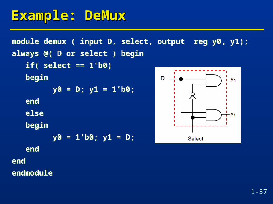
module demux ( input D, select, output reg y0, y1);
always @( D or select ) begin
if( select == 1’b0)
begin
y0 = D; y1 = 1’b0;
end
else
begin
y0 = 1’b0; y1 = D;
end
end
endmodule
module demux ( input D, select, output reg y0, y1);
always @( D or select ) begin
if( select == 1’b0)
begin
y0 = D; y1 = 1’b0;
end
else
begin
y0 = 1’b0; y1 = D;
end
end
endmodule

1-38
Example: Arithmetic UnitExample: Arithmetic UnitExample: Arithmetic UnitExample: Arithmetic Unit
module arithmetic #(parameter width=8)
(input [width-1:0] A, B, input [1:0] Sel,
output reg [width-1:0] Y, output reg Cout);
always @(A or B or Sel) begin
case (Sel)
2'b 00 : {Cout,Y} = A+B;
2'b 01 : {Cout,Y} = A-B;
2'b 10 : {Cout,Y} = A+1;
2'b 11 : {Cout,Y} = A-1;
default: begin Cout=0; Y=0; end
endcase
end
endmodule

1-39
Example: Logic UnitExample: Logic UnitExample: Logic UnitExample: Logic Unit
module logic #(parameter width=4)
(input [width-1:0] A, B, input [2:0] Sel,
output reg [width-1:0] Y);
always @(A or B or Sel) begin
case (Sel)
3'b 000 : Y = A & B; // A and B
3'b 001 : Y = A | B; // A or B
3'b 010 : Y = A ^ B; // A xor B
3'b 011 : Y = ~A; // 1’s complement of A
3'b 100 : Y = ~(A & B); // A nand B
3'b 101 : Y = ~(A | B); // A nor B
default : Y = 0;
endcase
end
endmodule

1-40
D LatchD LatchD LatchD Latch
module dlatch (output q, input data, enable);
assign q = enable ? data: q;
endmodule
module dlatch2 (output reg q, input data, enable);
always @(enable, data)
if (enable == 1'b1) q <= data;
endmodule
module dlatch (output q, input data, enable);
assign q = enable ? data: q;
endmodule
module dlatch2 (output reg q, input data, enable);
always @(enable, data)
if (enable == 1'b1) q <= data;
endmodule

1-41
D Flip Flop – Synchronous Set/ResetD Flip Flop – Synchronous Set/ResetD Flip Flop – Synchronous Set/ResetD Flip Flop – Synchronous Set/Reset
module dff (output reg q, output q_bar, input data, set_b, reset_b, clk);
assign q_bar = !q;
always @(posedge clk) // Synchronous set/reset
if (reset_b == 1'b0) q <= 0;
else if (set_b == 1'b0) q <=1;
else q <= data;
endmodule
module dff (output reg q, output q_bar, input data, set_b, reset_b, clk);
assign q_bar = !q;
always @(posedge clk) // Synchronous set/reset
if (reset_b == 1'b0) q <= 0;
else if (set_b == 1'b0) q <=1;
else q <= data;
endmodule

1-42
D Flip Flop – Asynchronous Set/ResetD Flip Flop – Asynchronous Set/ResetD Flip Flop – Asynchronous Set/ResetD Flip Flop – Asynchronous Set/Reset
module dff2 (output reg q, output q_bar, input data, set_b, reset_b, clk);
assign q_bar = !q;
always @(posedge clk, negedge set_b, negedge reset_b )// Asynchronous set/reset
if (reset_b == 1'b0) q <= 0;
else if (set_b == 1'b0) q <=1;
else q <= data;
endmodule
module dff2 (output reg q, output q_bar, input data, set_b, reset_b, clk);
assign q_bar = !q;
always @(posedge clk, negedge set_b, negedge reset_b )// Asynchronous set/reset
if (reset_b == 1'b0) q <= 0;
else if (set_b == 1'b0) q <=1;
else q <= data;
endmodule

1-43
D Flip Flop – Asynchronous Set/ResetD Flip Flop – Asynchronous Set/ResetD Flip Flop – Asynchronous Set/ResetD Flip Flop – Asynchronous Set/Reset
module dff3 (output reg q, output q_bar, input data, set_b, reset_b, clk);
assign q_bar = !q;
always @(clk, set_b, reset_b ) // Asynchronous set/reset
if (reset_b == 1'b0) q <= 0;
else if (set_b == 1'b0) q <=1;
else @(posedge clk) q <= data;
endmodule
module dff3 (output reg q, output q_bar, input data, set_b, reset_b, clk);
assign q_bar = !q;
always @(clk, set_b, reset_b ) // Asynchronous set/reset
if (reset_b == 1'b0) q <= 0;
else if (set_b == 1'b0) q <=1;
else @(posedge clk) q <= data;
endmodule

1-44
Data Flow/ RTL ModelsData Flow/ RTL ModelsData Flow/ RTL ModelsData Flow/ RTL Models
Data flow models describe concurrent operations on signals where computations are initiated at active edges of a clock and completed to be stored in a register at next active edge.
Also referred to as Register Transfer Level (RTL) as they describe transfer of data among registers.
A behavioral model of combinational logic can be described using concurrent assign statements or always statements.
A behavioral model of sequential logic can be described using always statements.

1-45
Shift RegisterShift RegisterShift RegisterShift Register
module shiftreg (output reg A, input E, clk, rst);
reg B, C, D;
always @(posedge clk, posedge rst) begin
if (rst == 1'b1) begin A=0; B=0; C=0; D=0; end
else begin
A = B;
B = C;
C = D;
D = E;
end
end
endmodule
module shiftreg (output reg A, input E, clk, rst);
reg B, C, D;
always @(posedge clk, posedge rst) begin
if (rst == 1'b1) begin A=0; B=0; C=0; D=0; end
else begin
A = B;
B = C;
C = D;
D = E;
end
end
endmodule

1-46
Shift RegisterShift RegisterShift RegisterShift Register
module shiftreg2 (output reg A, input E, clk, rst);
reg B, C, D;
always @(posedge clk, posedge rst) begin
if (rst == 1'b1) begin A=0; B=0; C=0; D=0; end
else begin
D = E;
C = D;
B = C;
A = B;
end
end
endmodule
module shiftreg2 (output reg A, input E, clk, rst);
reg B, C, D;
always @(posedge clk, posedge rst) begin
if (rst == 1'b1) begin A=0; B=0; C=0; D=0; end
else begin
D = E;
C = D;
B = C;
A = B;
end
end
endmodule
What will happen in this model?

1-47
Shift RegisterShift RegisterShift RegisterShift Register
module shiftreg3 (output reg A, input E, clk, rst);
reg B, C, D;
always @(posedge clk, posedge rst) begin
if (rst == 1'b1) begin A=0; B=0; C=0; D=0; end
else begin
A <= B;
B <= C;
C <= D;
D <= E;
end
end
endmodule
module shiftreg3 (output reg A, input E, clk, rst);
reg B, C, D;
always @(posedge clk, posedge rst) begin
if (rst == 1'b1) begin A=0; B=0; C=0; D=0; end
else begin
A <= B;
B <= C;
C <= D;
D <= E;
end
end
endmodule
Non-blocking assignments (<=)execute concurrently. So they areorder independent.

1-48
Behavioral Models of MultiplexorBehavioral Models of MultiplexorBehavioral Models of MultiplexorBehavioral Models of Multiplexor
module Mux_4_1 #(parameter width=32)
(output [width-1:0] mux_out, input [width-1:0] data_3, data_2, data_1, data_0, input [1:0] select, input enable);
reg [width-1:0] mux_int;
assign mux_out = enable ? mux_int : 'bz;
always @(data_3, data_2, data_1, data_0, select)
case (select)
0: mux_int = data_0;
1: mux_int = data_1;
2: mux_int = data_2;
3: mux_int = data_3;
default: mux_int = 'bx;
endcase
endmodule

1-49
Behavioral Models of MultiplexorBehavioral Models of MultiplexorBehavioral Models of MultiplexorBehavioral Models of Multiplexor
module Mux_4_1_IF #(parameter width=32)
(output [width-1:0] mux_out, input [width-1:0] data_3, data_2, data_1, data_0, input [1:0] select, input enable);
reg [width-1:0] mux_int;
assign mux_out = enable ? mux_int : 'bz;
always @(data_3, data_2, data_1, data_0, select)
if (select==0) mux_int = data_0; else
if (select==1) mux_int = data_1; else
if (select==2) mux_int = data_2; else
if (select==3) mux_int = data_3; else mux_int = 'bx;
endmodule

1-50
Behavioral Models of MultiplexorBehavioral Models of MultiplexorBehavioral Models of MultiplexorBehavioral Models of Multiplexor
module Mux_4_1_CA #(parameter width=32)
(output [width-1:0] mux_out, input [width-1:0] data_3, data_2, data_1, data_0, input [1:0] select, input enable);
wire [width-1:0] mux_int;
assign mux_out = enable ? mux_int : 'bz;
assign mux_int = (select==0) ? data_0:
(select==1) ? data_1:
(select==2) ? data_2:
(select==3) ? data_3: 'bx;
endmodule

1-51
Behavioral Models of EncoderBehavioral Models of EncoderBehavioral Models of EncoderBehavioral Models of Encoder
module encoder (output reg [2:0] Code, input [7:0] Data);
always @(Data)
if (Data==8'b00000001) Code = 0; else
if (Data==8'b00000010) Code = 1; else
if (Data==8'b00000100) Code = 2; else
if (Data==8'b00001000) Code = 3; else
if (Data==8'b00010000) Code = 4; else
if (Data==8'b00100000) Code = 5; else
if (Data==8'b01000000) Code = 6; else
if (Data==8'b10000000) Code = 7; else
Code = 'bx;
endmodule

1-52
Behavioral Models of EncoderBehavioral Models of EncoderBehavioral Models of EncoderBehavioral Models of Encoder
module priority (output reg [2:0] Code, output valid_data, input [7:0] Data);
assign valid_data = | Data;
always @(Data)
if (Data[7]) Code = 7; else
if (Data[6]) Code = 6; else
if (Data[5]) Code = 5; else
if (Data[4]) Code = 4; else
if (Data[3]) Code = 3; else
if (Data[2]) Code = 2; else
if (Data[1]) Code = 1; else
if (Data[0]) Code = 0; else
Code = 'bx;
endmodule

1-53
Behavioral Models of EncoderBehavioral Models of EncoderBehavioral Models of EncoderBehavioral Models of Encoder
module priority2 (output reg [2:0] Code, output valid_data, input [7:0] Data);
assign valid_data = | Data;
always @(Data)
case (Data)
8'b1xxxxxxx : Code = 7;
8'b01xxxxxx : Code = 6;
8'b001xxxxx : Code = 5;
8'b0001xxxx : Code = 4;
8'b00001xxx : Code = 3;
8'b000001xx : Code = 2;
8'b0000001x : Code = 1;
8'b00000001 : Code = 0;
default: Code = 'bx;
endcase
endmodule

1-54
Behavioral Models of DecoderBehavioral Models of DecoderBehavioral Models of DecoderBehavioral Models of Decoder
module decoder (output reg [7:0] Data, input [2:0] Code);
always @(Code)
if (Code == 0 ) Data= 8'b00000001; else
if (Code == 1 ) Data= 8'b00000010; else
if (Code == 2 ) Data= 8'b00000100; else
if (Code == 3 ) Data= 8'b00001000; else
if (Code == 4 ) Data= 8'b00010000; else
if (Code == 5 ) Data= 8'b00100000; else
if (Code == 6 ) Data= 8'b01000000; else
if (Code == 7 ) Data= 8'b10000000; else
Data = 'bx;
endmodule

1-55
Seven Segment Display DecoderSeven Segment Display DecoderSeven Segment Display DecoderSeven Segment Display Decoder
module Seven_Segment_Display (output reg [6:0] Display, input [3:0] BCD);
parameter BLANK = 7’b111_1111; parameter ZERO= 7’b000_0001; //abc_defg
parameter ONE= 7’b100_1111; parameter TWO= 7’b001_0010;
parameter THREE= 7’b000_0110; parameter FOUR= 7’b100_1100;
parameter FIVE= 7’b010_0100; parameter SIX= 7’b010_0000;
parameter SEVEN= 7’b000_1111; parameter EIGHT= 7’b000_0000;
parameter NINE= 7’b000_0100;
always @(BCD)
case (BCD)
0: Display = ZERO; 1: Display = ONE;
2: Display = TWO; 3: Display = THREE;
4: Display = FOUR; 5 : Display = FIVE;
6: Display = SIX; 7: Display = SEVEN;
8: Display = EIGHT; 9: Display = NINE;
default: DISPLAY = BLANK;
endcase
endmodule

1-56
Linear Feedback Shift Register (LFSR)Linear Feedback Shift Register (LFSR)Linear Feedback Shift Register (LFSR)Linear Feedback Shift Register (LFSR)

1-57
Linear Feedback Shift Register (LFSR)Linear Feedback Shift Register (LFSR)Linear Feedback Shift Register (LFSR)Linear Feedback Shift Register (LFSR)

1-58
Linear Feedback Shift Register (LFSR)Linear Feedback Shift Register (LFSR)Linear Feedback Shift Register (LFSR)Linear Feedback Shift Register (LFSR)
module LFSR #(parameter Length=8, initial_state = 8'b1001_0001, //91h
parameter [Length: 1] Tap_Coefficient = 8'b1100_1111)
(input clock, reset_b, output reg [1:Length] Y);
always@ (posedge clock)
if (reset_b == 1'b0) Y<= initial_state;
else begin
Y[1] <= Y[8];
Y[2] <= Tap_Coefficient[7]? Y[1]^Y[8]:Y[1];
Y[3] <= Tap_Coefficient[6]? Y[2]^Y[8]:Y[2];
Y[4] <= Tap_Coefficient[5]? Y[3]^Y[8]:Y[3];
Y[5] <= Tap_Coefficient[4]? Y[4]^Y[8]:Y[4];
Y[6] <= Tap_Coefficient[3]? Y[5]^Y[8]:Y[5];
Y[7] <= Tap_Coefficient[2]? Y[6]^Y[8]:Y[6];
Y[8] <= Tap_Coefficient[1]? Y[7]^Y[8]:Y[7];
end
endmodule

1-59
Repetitive AlgorithmsRepetitive AlgorithmsRepetitive AlgorithmsRepetitive Algorithms
for loop:• for (initial_statement; control expression; index_statement)
statement_for_execution;
• initial_statement executes once to initialize a register variable (i.e. an integer of reg) that controls the loop
• If control_expression is true the statement_for_execution will execute
• After the statement_for_execution has executed, the index_statement will execute (usually to increment a counter)
• Then the control expression is checked again and if false the loop terminates.

1-60
Linear Feedback Shift Register (LFSR)Linear Feedback Shift Register (LFSR)Linear Feedback Shift Register (LFSR)Linear Feedback Shift Register (LFSR)
module LFSR2 #(parameter Length=8, initial_state = 8'b1001_0001, //91h
parameter [Length:1] Tap_Coefficient = 8'b1100_1111)
(input clock, reset_b, output reg [1:Length] Y);
integer k;
always@ (posedge clock)
if (reset_b == 1'b0) Y<= initial_state;
else begin
for (k = 2; k <= Length; k = k+1)
if (Tap_Coefficient[Length-k+1]==1)
Y[k] <= Y[k-1]^Y[Length];
else Y[k] <= Y[k-1];
Y[1] <= Y[Length];
end
endmodule

1-61
Linear Feedback Shift Register (LFSR)Linear Feedback Shift Register (LFSR)Linear Feedback Shift Register (LFSR)Linear Feedback Shift Register (LFSR)
module LFSR3 #(parameter Length=8, initial_state = 8'b1001_0001, //91h
parameter [Length:1] Tap_Coefficient = 8'b1100_1111)
(input clock, reset_b, output reg [1:Length] Y);
integer k;
always@ (posedge clock)
if (reset_b == 1'b0) Y<= initial_state;
else begin
for (k = 2; k <= Length; k = k+1)
Y[k] <= Tap_Coefficient[Length-k+1]?Y[k-1]^Y[Length]:Y[k-1];
Y[1] <= Y[Length];
end
endmodule

1-62
MajorityMajorityMajorityMajority
module Majority #(parameter size=8, max=3, majority=5)
(input [size-1:0] Data,
output reg Y);
reg [max-1:0] count;
integer k;
always@ (Data) begin
count = 0;
for (k=0; k < size; k = k+1)
if (Data[k] == 1) count = count + 1;
Y = (count >= majority);
end
endmodule
module Majority #(parameter size=8, max=3, majority=5)
(input [size-1:0] Data,
output reg Y);
reg [max-1:0] count;
integer k;
always@ (Data) begin
count = 0;
for (k=0; k < size; k = k+1)
if (Data[k] == 1) count = count + 1;
Y = (count >= majority);
end
endmodule

1-63
Repetitive AlgorithmsRepetitive AlgorithmsRepetitive AlgorithmsRepetitive Algorithms
repeat loop• repeat (expression) statement;
• executes an associated statement or block of statements a specified number of times unless it is terminated by a disable statement within the activity flow
Example: a repeat loop is used to initialize a memory arrayword_address = 0;repeat (memory_size)begin
memory[word_address]=0;word_address = word_address+1;
end

1-64
Repetitive AlgorithmsRepetitive AlgorithmsRepetitive AlgorithmsRepetitive Algorithms
while loop• while (expression) statement;
• Executes repeatedly while a Boolean expression is true
Example:while (enable) begin
@(posedge clock) count <= count + 1;end
while loop• while (expression) statement;
• Executes repeatedly while a Boolean expression is true
Example:while (enable) begin
@(posedge clock) count <= count + 1;end

1-65
Repetitive AlgorithmsRepetitive AlgorithmsRepetitive AlgorithmsRepetitive Algorithms
module CountOnes (input [7:0] reg_a, output reg [3:0] count);
always@ (reg_a)
begin: count_of_1s // declares a named block of statements
reg [7:0] temp_reg;
count = 0;
temp_reg = reg_a; // load a data word
while (temp_reg)
begin
if (temp_reg[0]) count = count + 1; // count = count + temp_reg[0];
temp_reg = temp_reg >> 1;
end
end
endmodule

1-66
Clock GeneratorsClock GeneratorsClock GeneratorsClock Generators
module clockgen(output reg clock);
parameter half_cycle = 50;
parameter stop_time = 350;
initial
begin: clock_loop
clock = 0;
forever
begin
#half_cycle clock = 1;
#half_cycle clock = 0;
end
end
initial
#stop_time disable clock_loop;
endmodule
module clockgen(output reg clock);
parameter half_cycle = 50;
parameter stop_time = 350;
initial
begin: clock_loop
clock = 0;
forever
begin
#half_cycle clock = 1;
#half_cycle clock = 0;
end
end
initial
#stop_time disable clock_loop;
endmodule

1-67
Disable StatementDisable StatementDisable StatementDisable Statement
Disable statement is used to prematurely terminate a named block of procedural statements. Execution is transferred to the statement that immediately follows the named block.
module find_first_one (output reg [3:0] index_value, input [15:0] A_word, input trigger);
always @(posedge trigger)
begin: search_for_1
for (index_value=0; index_value<15; index_value=index_value+1)
if (A_word[index_value] == 1) disable search_for_1;
end
endmodule

1-68
Machines with Multicycle OperationsMachines with Multicycle OperationsMachines with Multicycle OperationsMachines with Multicycle Operations
A machine to form the sum of four successive samples of a datapath
module add_4cycle (output reg [5:0] sum, input [3:0] data, input clk, reset);
always @ (posedge clk) begin: add_loop
if (reset == 1’b1) disable add_loop; else sum <= data;
@ (posedge clk) if (reset == 1’b1) disable add_loop; else sum <= sum + data;
@ (posedge clk) if (reset == 1’b1) disable add_loop; else sum <= sum + data;
@ (posedge clk) if (reset == 1’b1) disable add_loop; else sum <= sum + data;
end
endmodule

1-69
Machines with Multicycle OperationsMachines with Multicycle OperationsMachines with Multicycle OperationsMachines with Multicycle Operations

1-70
Tasks and FunctionsTasks and FunctionsTasks and FunctionsTasks and Functions
Tasks create a hierarchical organization of procedural statements within a Verilog behavior.
Functions substitute for an expression. Tasks and functions facilitate a readable style of code,
with a single identifier conveying the meaning of many lines of code.
Encapsulation of Verilog code into tasks or functions hides the details of an implementation.
Overall, tasks and functions improve the readability, portability and maintainability of a model.

1-71
TasksTasksTasksTasks
Tasks are declared within a module and they may be referenced from within a cyclic or single-pass behavior.
A task can have parameters passed to it and results of executing a task can be passed back to environment.
When a task is called, copies of parameters in environment are associated with inputs, outputs, and inouts within the task according to order of declaration
The variables in environment are visible to a task. Local variables may be declared within a task. A task can call itself.

1-72
TasksTasksTasksTasks
A task must be named and may include declarations of any number of : parameter, input, output, inout, reg, integer, real, time, realtime.
Arguments of a task retain the type they hold in the environment that invokes the task.
All arguments of a task are passed by a value. The basic syntax of a task is:
task [task-id] ([arg]) ;begin
[statements] ;end
endtask [arg] is the argument declaration and is similar to port
declaration except that the default data type is reg and the wire data type can not be used as output

1-73
TasksTasksTasksTasks
module adder_task (output reg c_out, output reg [3:0] sum, input [3:0] data_a, data_b, input c_in, clk, reset);
always @(posedge clk, posedge reset)
if (reset == 1’b1) {c_out, sum} <= 0; else add_values(c_out, sum, data_a, data_b, c_in);
task add_values( output c_out, output [3:0] sum, input [3:0] data_a, data_b, input c_in);
{c_out, sum} <= data_a + (data_b + c_in);
endtask
endmodule

1-74
TasksTasksTasksTasks

1-75
TasksTasksTasksTasks

1-76
FunctionsFunctionsFunctionsFunctions
Verilog functions are declared within a parent module and can be referenced in any valid expression
A function is implemented by an expression and returns a value at the location of the function’s identifier.
Functions may implement only combinational behavior.
A function may not contain timing controls (#, @, wait), non-blocking statements.
Functions may not invoke a task but they may call other functions but not recursively.
Functions are expanded during synthesis and "flattened”

1-77
FunctionsFunctionsFunctionsFunctions
Basic syntax of a function is shown below:
[result-type] is the data type of the returned result (usually reg or integer)
Function name is specified by [func-id] Function value is returned by a statement like: func-id
= … ;
Basic syntax of a function is shown below:
[result-type] is the data type of the returned result (usually reg or integer)
Function name is specified by [func-id] Function value is returned by a statement like: func-id
= … ;
1-78
FunctionsFunctionsFunctionsFunctions
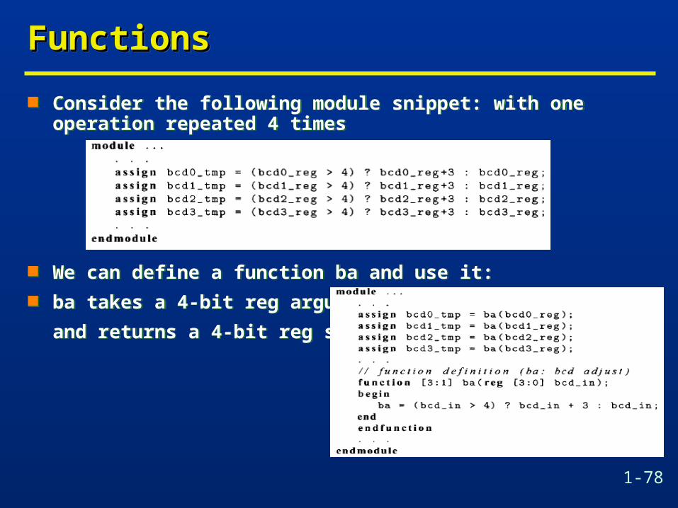
Consider the following module snippet: with one operation repeated 4 times
We can define a function ba and use it: ba takes a 4-bit reg argument
and returns a 4-bit reg signal
Consider the following module snippet: with one operation repeated 4 times
We can define a function ba and use it: ba takes a 4-bit reg argument
and returns a 4-bit reg signal

1-79
FunctionsFunctionsFunctionsFunctions
A function could be used is to calculate the constants whose values depend on other parameters:
Note that the function in this
example is evaluated during
pre-processing, it does
not infer any hardware
(the for loop is usually
not synthesizable)
A function could be used is to calculate the constants whose values depend on other parameters:
Note that the function in this
example is evaluated during
pre-processing, it does
not infer any hardware
(the for loop is usually
not synthesizable)

1-80
FunctionsFunctionsFunctionsFunctions
module word_aligner #(parameter word_size = 8)
(output [word_size-1:0] word_out, input [word_size-1:0] word_in);
assign word_out = aligned_word(word_in);
function [word_size-1:0] aligned_word;
input [word_size-1:0] word;
begin
aligned_word = word;
if (aligned_word != 0)
while (aligned_word[word_size-1]==0) aligned_word = aligned_word << 1;
end
endfunction
endmodule

1-81
FunctionsFunctionsFunctionsFunctions
module arithmetic_unit (
output [4:0] result_1,
output [3:0] result_2,
input [3:0] operand_1, operand_2);
assign result_1 = sum_of_operands (operand_1, operand_2);
assign result_2 = largest_operand (operand_1, operand_2);
function [4:0] sum_of_operands (input [3:0] operand_1, operand_2);
sum_of_operands = operand_1 + operand_2;
endfunction
function [3:0] largest_operand (input [3:0] operand_1, operand_2);
largest_operand = (operand_1 >= operand_2) ? operand_1: operand_2;
endfunction
endmodule

1-82
FunctionsFunctionsFunctionsFunctions

1-83
Behavioral Modeling of Control UnitBehavioral Modeling of Control UnitBehavioral Modeling of Control UnitBehavioral Modeling of Control Unit
module Controller (output reg Clr_P1_P0,Ld_P1_P0, Ld_R0, input En, Ld, clk, rst);
parameter S_idle = 2'b00, S_1=2'b01, S_full=2'b10, S_wait=2'b11;reg [1:0] state, next_state;
always @(posedge clk) if (rst) state <= S_idle; else state <= next_state;
always @(state, En, Ld) begin Clr_P1_P0 = 0; Ld_P1_P0=0; Ld_R0=0; case (state) S_idle: if (En) begin next_state=S_1; Ld_P1_P0=1; end else next_state=S_idle;

1-84
Behavioral Modeling of Control UnitBehavioral Modeling of Control UnitBehavioral Modeling of Control UnitBehavioral Modeling of Control UnitS_1: begin next_state=S_full; Ld_P1_P0=1; end S_full: if (!Ld) next_state=S_wait; else begin
Ld_R0=1; if (En) begin
next_state=S_1; Ld_P1_P0=1; end else begin
next_state=S_idle; Clr_P1_P0=1; end end S_wait: if (!Ld) next_state=S_wait; else begin
Ld_R0=1;if (En) begin next_state=S_1; Ld_P1_P0=1; endelse begin next_state=S_idle; Clr_P1_P0=1; end
endendcaseendendmodule
1-85
Behavioral Models of CountersBehavioral Models of CountersBehavioral Models of CountersBehavioral Models of Counters
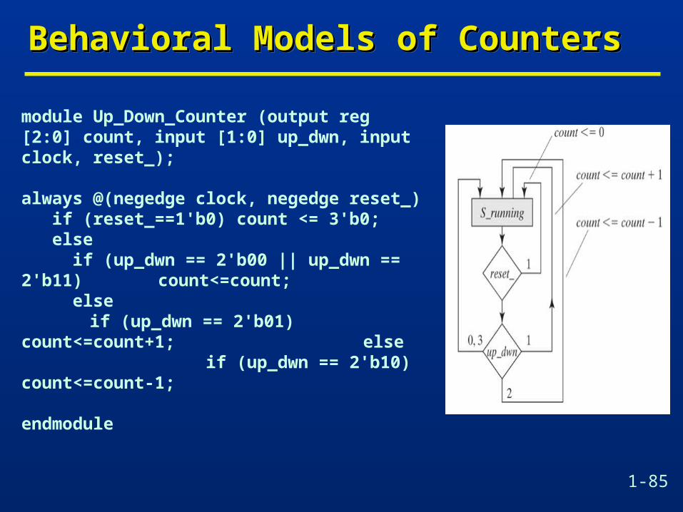
module Up_Down_Counter (output reg [2:0] count, input [1:0] up_dwn, input clock, reset_);
always @(negedge clock, negedge reset_) if (reset_==1'b0) count <= 3'b0; else if (up_dwn == 2'b00 || up_dwn == 2'b11)
count<=count; else
if (up_dwn == 2'b01) count<=count+1; else if (up_dwn == 2'b10) count<=count-1;
endmodule

1-86
Behavioral Models of CountersBehavioral Models of CountersBehavioral Models of CountersBehavioral Models of Counters
A ring counter asserts a single bit that circulates through the counter in a synchronous manner.
A ring counter asserts a single bit that circulates through the counter in a synchronous manner.

1-87
Behavioral Models of CountersBehavioral Models of CountersBehavioral Models of CountersBehavioral Models of Counters
module ring_counter #(parameter word_size=8)
(output reg [word_size-1:0] count, input enable, clock, reset);
always @ (posedge clock, posedge reset)
if (reset) count <= { {(word_size-1){1'b0}},1'b1};
else if (enable == 1'b1) count <= {count[word_size-2:0], count[word_size-1]};
endmodule
module ring_counter #(parameter word_size=8)
(output reg [word_size-1:0] count, input enable, clock, reset);
always @ (posedge clock, posedge reset)
if (reset) count <= { {(word_size-1){1'b0}},1'b1};
else if (enable == 1'b1) count <= {count[word_size-2:0], count[word_size-1]};
endmodule

1-88
Behavioral Models of CountersBehavioral Models of CountersBehavioral Models of CountersBehavioral Models of Counters
module Up_Down_Counter2 (
output reg [2:0] count,
input load, count_up, counter_on, clock, reset,
input [2:0] Data_in);
always @(posedge clock, posedge reset)
if (reset==1'b1) count <= 3'b0; else
if (load == 1'b1) count <= Data_in; else
if (counter_on == 1'b1) begin
if (count_up == 1'b1) count<=count+1;
else count<=count-1;
end
endmodule

1-89
Behavioral Models of Shift RegistersBehavioral Models of Shift RegistersBehavioral Models of Shift RegistersBehavioral Models of Shift Registers
module Shift_reg4 #(parameter word_size=4)
( output Data_out, input Data_in, clock, reset);
reg [word_size-1:0] Data_reg;
assign Data_out = Data_reg[0];
always @(posedge clock, negedge reset)
if (reset==1'b0) Data_reg <= {word_size{1'b0}};
else Data_reg <= {Data_in, Data_reg[word_size-1:1]};
endmodule

1-90
Parallel Load RegisterParallel Load RegisterParallel Load RegisterParallel Load Register
module Par_load_reg4 #(parameter word_size=4)
( output reg [word_size-1:0] Data_out,
input [word_size-1:0] Data_in,
input load, clock, reset);
always @(posedge clock, posedge reset)
if (reset==1'b0) Data_out <= {word_size{1'b0}};
else if (load==1'b1) Data_out <= Data_in;
endmodule
module Par_load_reg4 #(parameter word_size=4)
( output reg [word_size-1:0] Data_out,
input [word_size-1:0] Data_in,
input load, clock, reset);
always @(posedge clock, posedge reset)
if (reset==1'b0) Data_out <= {word_size{1'b0}};
else if (load==1'b1) Data_out <= Data_in;
endmodule

1-91
Barrel ShifterBarrel ShifterBarrel ShifterBarrel Shifter
module barrel_shifter #(parameter word_size=8)
( output reg [word_size-1:0] Data_out,
input [word_size-1:0] Data_in,
input load, clock, reset);
always @(posedge clock, posedge reset)
if (reset==1'b0) Data_out <= {word_size{1'b0}};
else if (load==1'b1) Data_out <= Data_in;
else Data_out <= {Data_out[word_size-2:0], Data_out[word_size-1]};
endmodule

1-92
Universal Shift RegisterUniversal Shift RegisterUniversal Shift RegisterUniversal Shift Register
module Universal_Shift_Register #(parameter word_size=4)
( output reg [word_size-1:0] Data_Out, output MSB_Out, LSB_Out,
input [word_size-1:0] Data_In, input MSB_In, LSB_In,
input s1, s0, clk, rst);
assign MSB_Out = Data_Out[word_size-1];
assign LSB_Out = Data_Out[0];
always @(posedge clk)
if (rst==1'b1) Data_Out <= 0;
else case ({s1,s0})
0: Data_Out <= Data_Out;
1: Data_Out <= {MSB_In, Data_Out[word_size-1:1]};
2: Data_Out <= {Data_Out[word_size-2:0], LSB_In};
3: Data_Out <= Data_In;
endcase
endmodule

1-93
Register FilesRegister FilesRegister FilesRegister Files
module Register_File #(parameter word_size=32, addr_size=5)
( output reg [word_size-1:0] Data_Out1, Data_Out2,
input [word_size-1:0] Data_In,
input [addr_size-1:0] Read_Addr_1, Read_Addr_2, Write_Addr,
input Write_Enable, Clock);
reg [word_size-1:0] Reg_File[31:0];
assign Data_Out_1 = Reg_File[Read_Addr_1];
assign Data_Out_12= Reg_File[Read_Addr_2];
always @(posedge Clock)
if (Write_Enable==1'b1)
Reg_File[Write_Addre] <= Data_In;
endmodule