Embed Size (px)
Citation preview
Hands-On LabCode Discovery using the Architecture Tools in Visual Studio 2010 Ultimate
Lab version: 1.0.0
Last updated: 5/18/2023
CONTENTS
OVERVIEW................................................................................................................................................. 3
EXERCISE 1: DEPENDENCY GRAPH GENERATION AND NAVIGATION..............................................4
EXERCISE 2: WORKING WITH GRAPH NODES AND GROUPING.......................................................16
Overview
In this lab you will learn how to generate and navigate dependency graphs with Visual Studio 2010 Ultimate in order better understand and communicate system architecture.
System Requirements
In order to complete this lab you will need the Visual Studio 2010 virtual machine provided by Microsoft. For more information on acquiring and using this virtual machine, please see this blog post.
Exercises
This Hands-On Lab comprises the following exercises:
1. Dependency Graph Generation and Navigation
2. Working with Graph Nodes and Grouping
Estimated time to complete this lab: 60 minutes.
Next Step
Exercise 1: Dependency Graph Generation and Navigation
Exercise 1: Dependency Graph Generation and Navigation
In this exercise, you will learn how to generate a dependency graph that shows relationships between application assembly types (such as calls, inherits from, returns, and so on), generated generic types, and external assembly types. Relationship navigation and zooming will also be introduced.
1. Log in as Abu Obeida Bakhach (Dev) if you have not already done so. The password is P2ssw0rd (capital letter P, the number two, the letter s, the letter s, the letter w, the number zero, the letter r, and the letter d). Please see “Working with the Visual Studio 2010 Virtual Machine” for instructions on how to log into the VM.
2. Open Microsoft Visual Studio from Start | All Programs | Microsoft Visual Studio 2010 | Microsoft Visual Studio 2010.
3. In Source Control Explorer (View | Other Windows | Source Control Explorer), navigate to Tailspin Toys | Development | Iteration 2 and double-click on the TailspinToys.sln file to open the Tailspin Toys solution.
4. Rebuild the solution (Build | Rebuild Solution from the main menu). This step may take a few minutes to complete.
5. From the main menu, navigate to Architecture | Generate Dependency Graph to expose the options available (By Assembly, By Namespace, By Class, Custom, and so on).
Figure 1Dependency graph options
6. Select Custom… and take note of the various levels of detail that can be included in the generated dependency graph. Note that a sample preview is generated showing the general graph structure for the currently selected options.
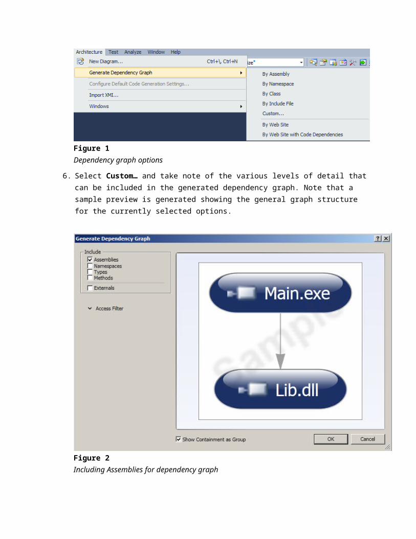
Figure 2Including Assemblies for dependency graph
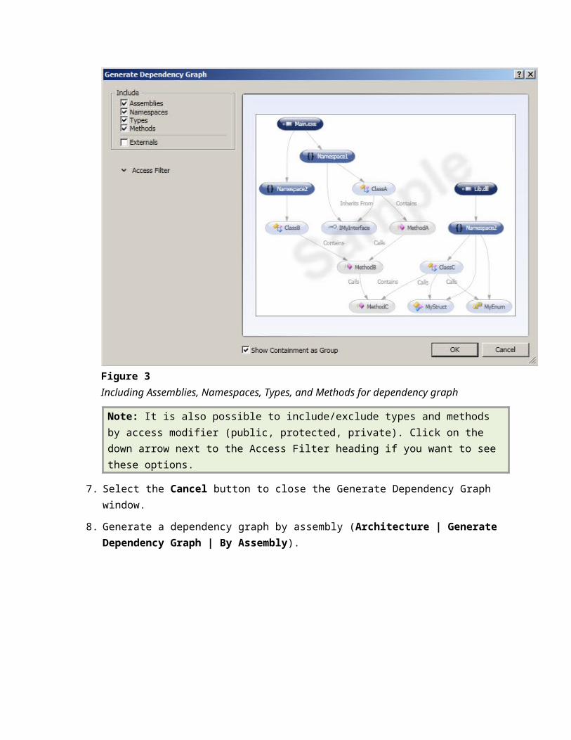
Figure 3Including Assemblies, Namespaces, Types, and Methods for dependency graph
Note: It is also possible to include/exclude types and methods by access modifier (public, protected, private). Click on the down arrow next to the Access Filter heading if you want to see these options.
7. Select the Cancel button to close the Generate Dependency Graph window.
8. Generate a dependency graph by assembly (Architecture | Generate Dependency Graph | By Assembly).
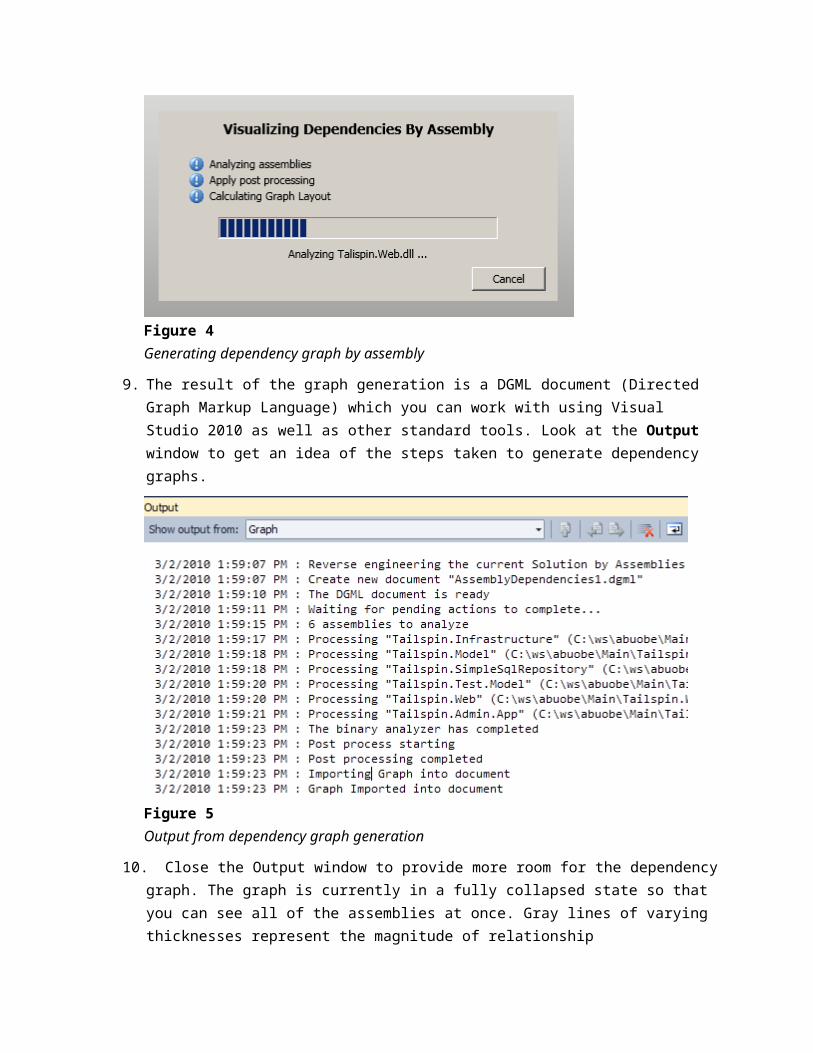
Figure 4Generating dependency graph by assembly
9. The result of the graph generation is a DGML document (Directed Graph Markup Language) which you can work with using Visual Studio 2010 as well as other standard tools. Look at the Output window to get an idea of the steps taken to generate dependency graphs.
Figure 5Output from dependency graph generation
10. Close the Output window to provide more room for the dependency graph. The graph is currently in a fully collapsed state so that you can see all of the assemblies at once. Gray lines of varying thicknesses represent the magnitude of relationship interdependencies between assemblies, with thicker lines equating to more relationships.
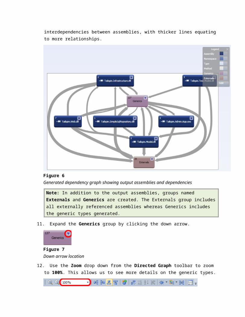
Figure 6Generated dependency graph showing output assemblies and dependencies
Note: In addition to the output assemblies, groups named Externals and Generics are created. The Externals group includes all externally referenced assemblies whereas Generics includes the generic types generated.
11. Expand the Generics group by clicking the down arrow.
Figure 7Down arrow location
12. Use the Zoom drop down from the Directed Graph toolbar to zoom to 100%. This allows us to see more details on the generic types.
Figure 8Location of Zoom drop down
Note: Zooming can also be done with the + and – magnifying glass icons next to the Zoom drop down, or alternatively using Ctrl + mouse scroll wheel.
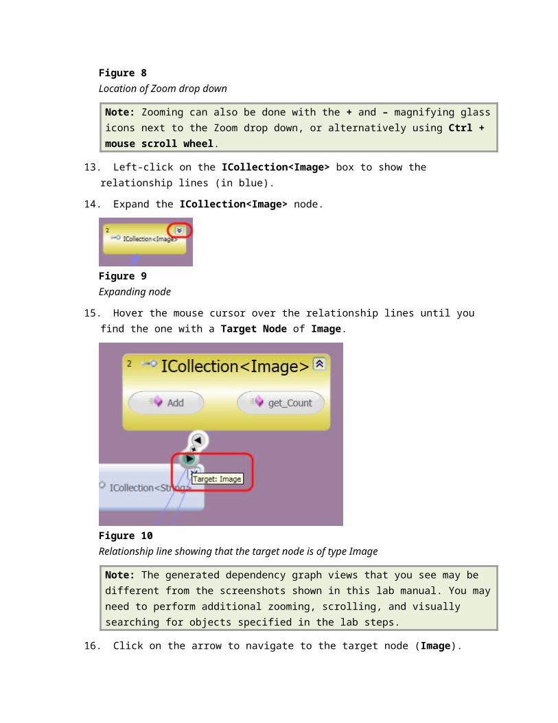
13. Left-click on the ICollection<Image> box to show the relationship lines (in blue).
14. Expand the ICollection<Image> node.
Figure 9Expanding node
15. Hover the mouse cursor over the relationship lines until you find the one with a Target Node of Image.
Figure 10Relationship line showing that the target node is of type Image
Note: The generated dependency graph views that you see may be different from the screenshots shown in this lab manual. You may need to perform additional zooming, scrolling, and visually searching for objects specified in the lab steps.
16. Click on the arrow to navigate to the target node (Image).
Note: The navigation control that appears when hovering over a blue relationship line exposes three actions. The two arrows navigate to either the source or the target node of the relationship (depending upon context). The + button will help you generate a new graph with just the source and target nodes.
17. After the graph is re-built and displayed, the Image class will be shown with all of its relationship lines.
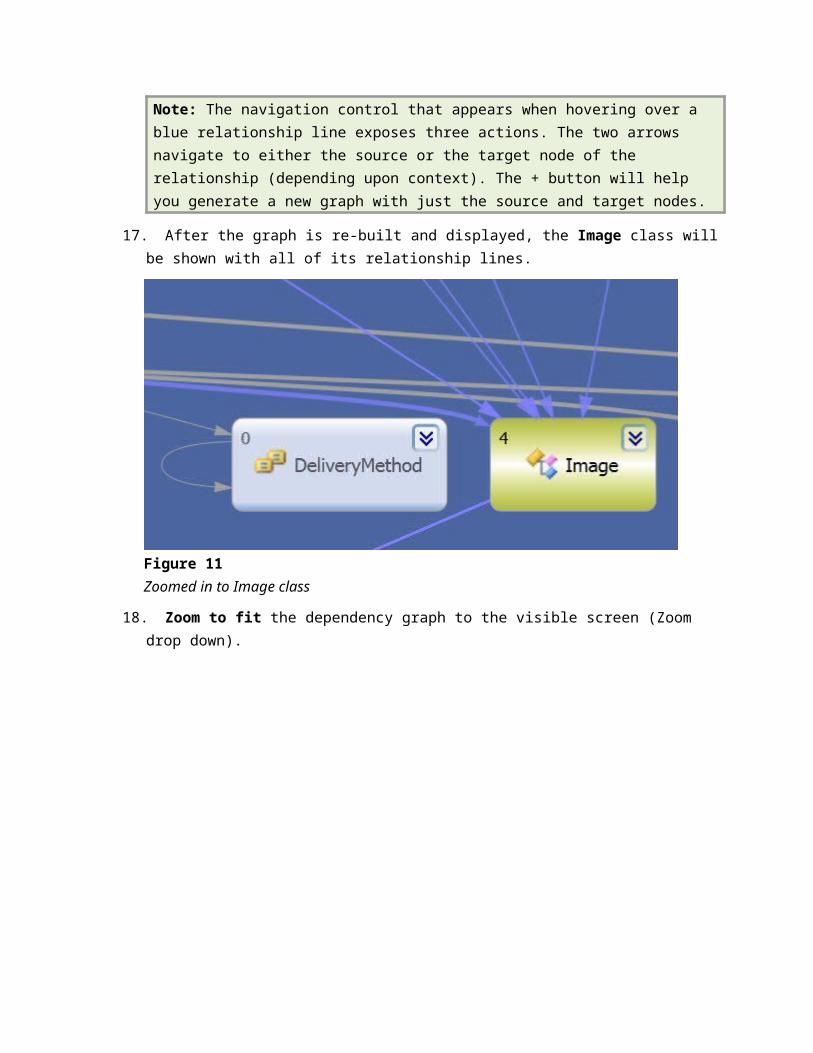
Figure 11Zoomed in to Image class
18. Zoom to fit the dependency graph to the visible screen (Zoom drop down).
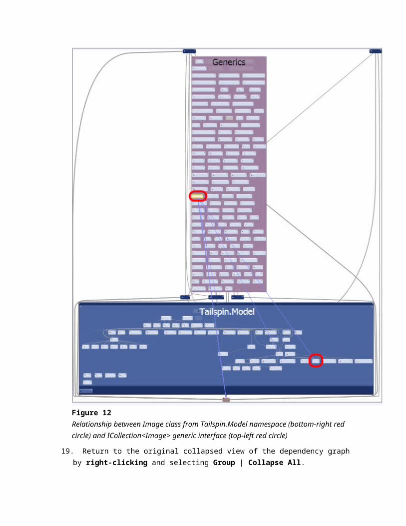
Figure 12Relationship between Image class from Tailspin.Model namespace (bottom-right red circle) and ICollection<Image> generic interface (top-left red circle)
19. Return to the original collapsed view of the dependency graph by right-clicking and selecting Group | Collapse All.
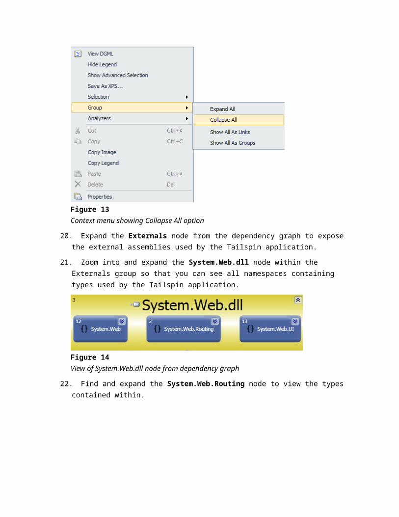
Figure 13Context menu showing Collapse All option
20. Expand the Externals node from the dependency graph to expose the external assemblies used by the Tailspin application.
21. Zoom into and expand the System.Web.dll node within the Externals group so that you can see all namespaces containing types used by the Tailspin application.
Figure 14View of System.Web.dll node from dependency graph
22. Find and expand the System.Web.Routing node to view the types contained within.
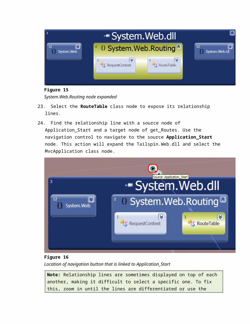
Figure 15System.Web.Routing node expanded
23. Select the RouteTable class node to expose its relationship lines.
24. Find the relationship line with a source node of Application_Start and a target node of get_Routes. Use the navigation control to navigate to the source Application_Start node. This action will expand the Tailspin.Web.dll and select the MvcApplication class node.
Figure 16Location of navigation button that is linked to Application_Start
Note: Relationship lines are sometimes displayed on top of each another, making it difficult to select a specific one. To fix this, zoom in until the lines are differentiated or use the graph layout buttons to the right of the Zoom drop down in the Directed Graph toolbar.
25. Navigating to the Application_Start node takes you to a drilled-in view by expanding the Tailspin.Web.dll assembly, the Tailspin.Web namespace, the MvcApplication class, and finally the Application_Start method.
Figure 17
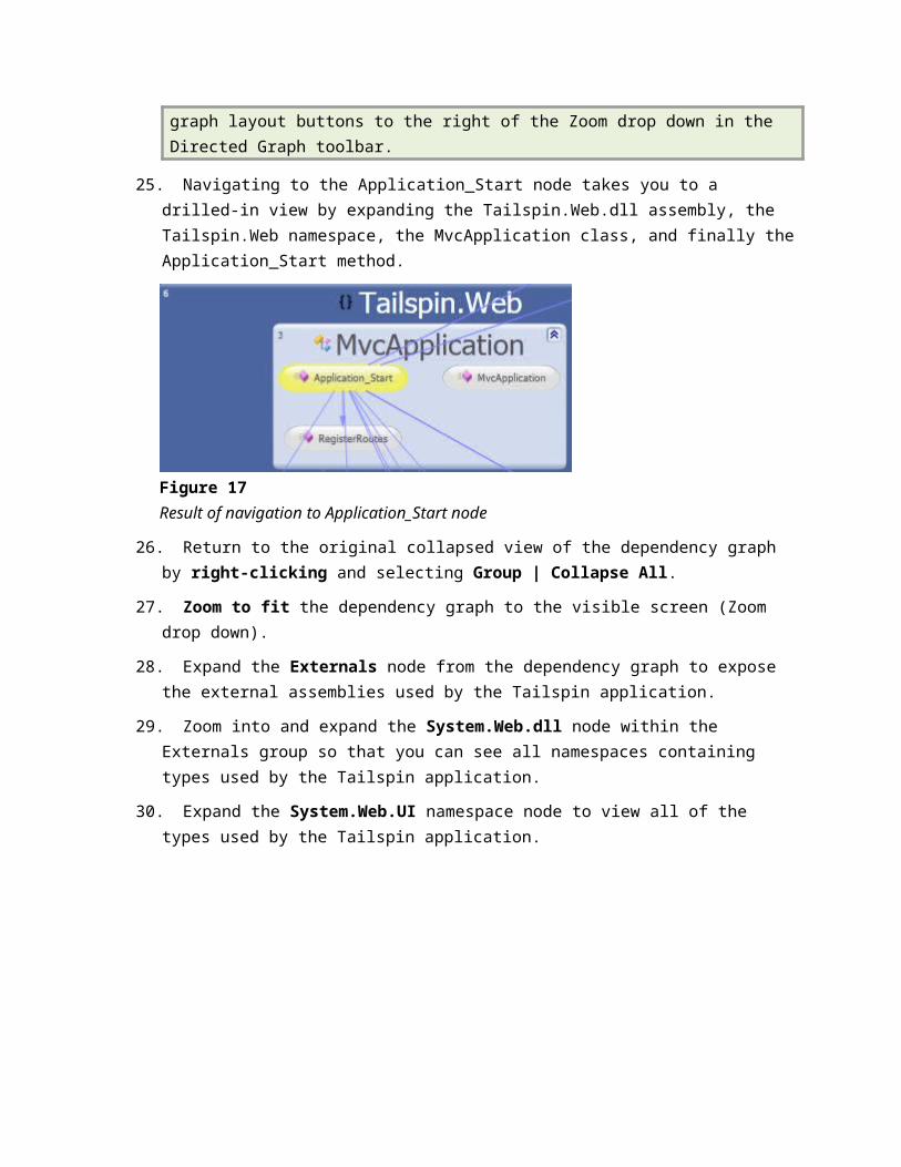
Result of navigation to Application_Start node
26. Return to the original collapsed view of the dependency graph by right-clicking and selecting Group | Collapse All.
27. Zoom to fit the dependency graph to the visible screen (Zoom drop down).
28. Expand the Externals node from the dependency graph to expose the external assemblies used by the Tailspin application.
29. Zoom into and expand the System.Web.dll node within the Externals group so that you can see all namespaces containing types used by the Tailspin application.
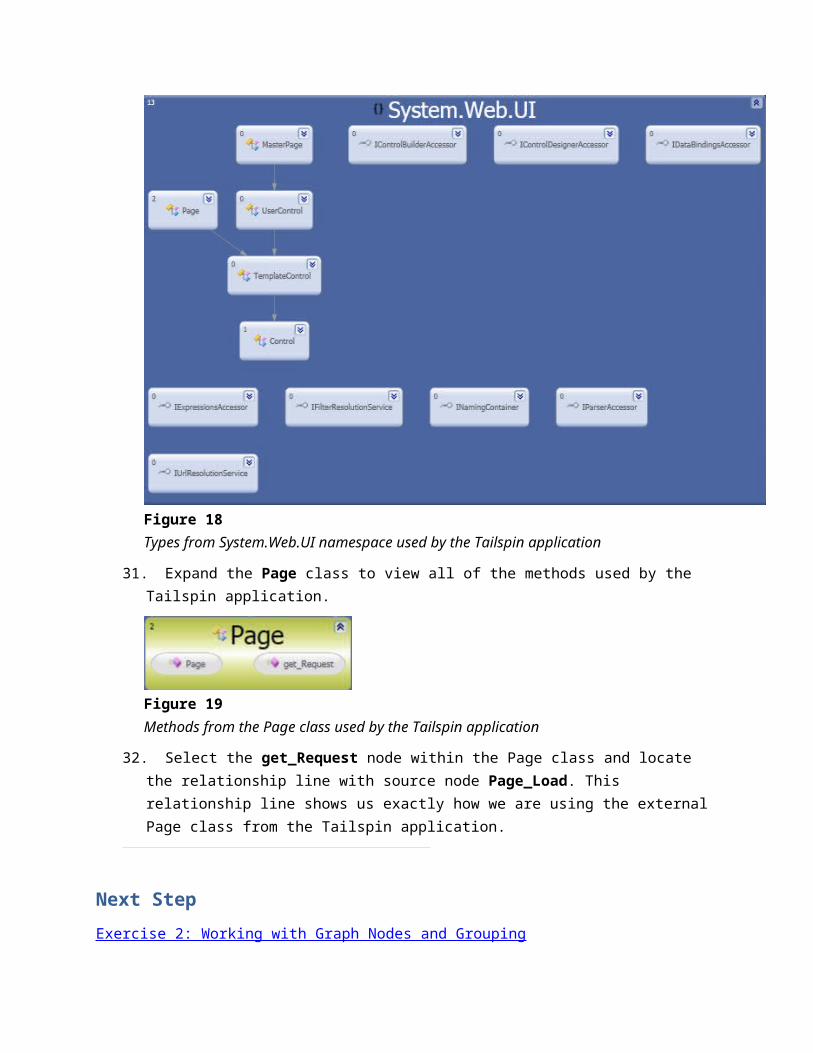
30. Expand the System.Web.UI namespace node to view all of the types used by the Tailspin application.
Figure 18Types from System.Web.UI namespace used by the Tailspin application
31. Expand the Page class to view all of the methods used by the Tailspin application.
Figure 19Methods from the Page class used by the Tailspin application
32. Select the get_Request node within the Page class and locate the relationship line with source node Page_Load. This relationship line shows us exactly how we are using the external Page class from the Tailspin application.
Next Step
Exercise 2: Working with Graph Nodes and Grouping

Exercise 2: Working with Graph Nodes and Grouping
In this exercise, you will learn how to reduce dependency graph complexity by removing unwanted nodes, adjusting the grouping of nodes, and modifying graph node properties.
1. Return to the original collapsed view of the dependency graph by right-clicking and selecting Group | Collapse All.
2. Zoom to fit the dependency graph to the visible screen (Zoom drop down).
3. Expand the Externals node from the dependency graph to expose the external assemblies used by the Tailspin application.
4. Select both of the mscorlib.dll assembly nodes and press the Delete key to remove them from the graph. The rationale behind removing this node, as well as many other commonly used external assemblies and types, might be that it adds too much noise to the graph and makes it difficult to navigate efficiently.
Figure 20Location of mscorlib.dll
Note: Multiple nodes labeled mscorlib.dll exist because the application references two different versions of the assembly.
5. Delete both System.dll nodes from the Externals group as well.
Note: The gray relationship lines connected to the Externals group stop at the boundary of the group. The purpose of this is to reduce the visual complexity of the dependency graph. If you remove the Externals grouping, you will be able to see all the direct relationship lines between external and internal assemblies as well as more detail between assemblies currently grouped within Externals.
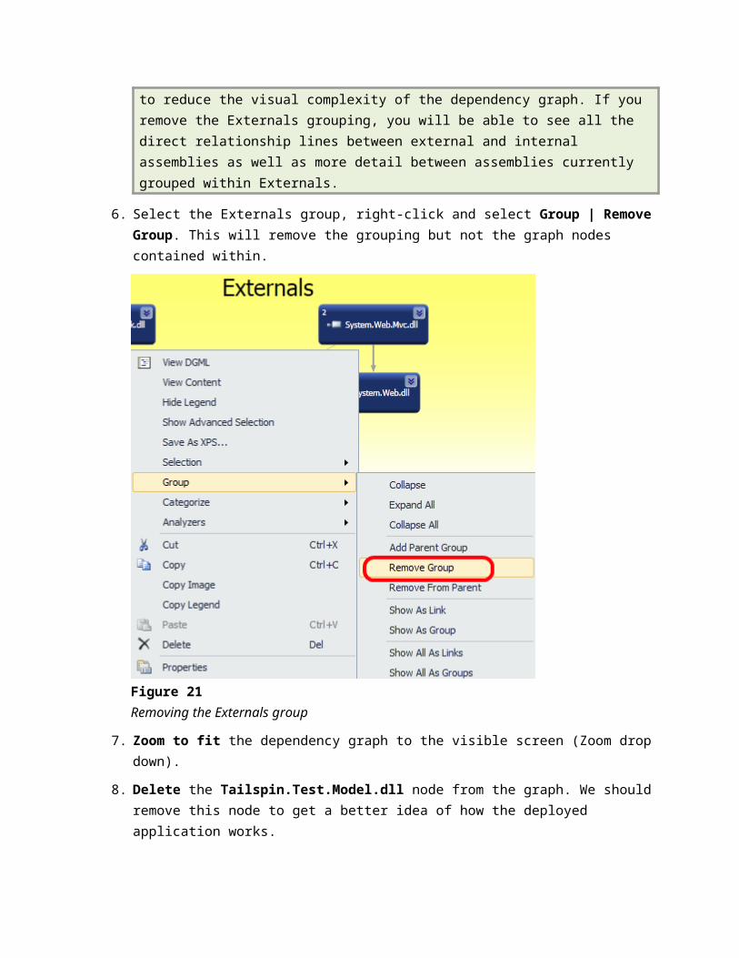
6. Select the Externals group, right-click and select Group | Remove Group. This will remove the grouping but not the graph nodes contained within.
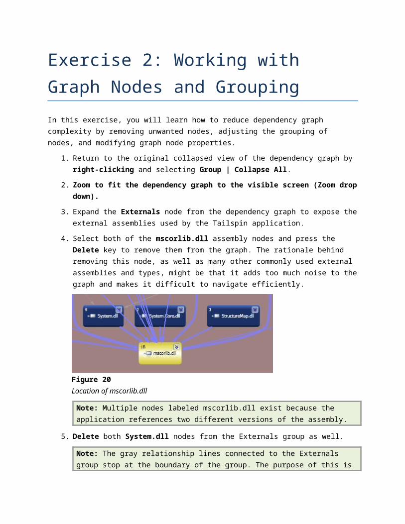
Figure 21Removing the Externals group
7. Zoom to fit the dependency graph to the visible screen (Zoom drop down).
8. Delete the Tailspin.Test.Model.dll node from the graph. We should remove this node to get a better idea of how the deployed application works.
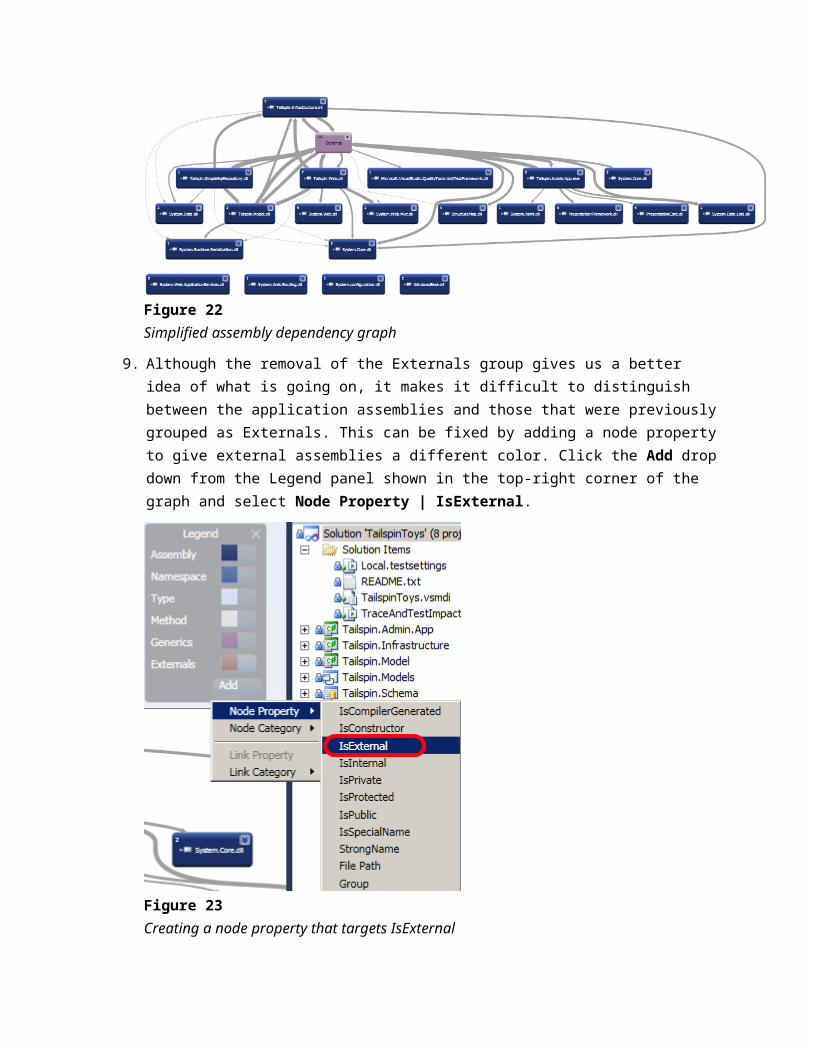
Figure 22Simplified assembly dependency graph
9. Although the removal of the Externals group gives us a better idea of what is going on, it makes it difficult to distinguish between the application assemblies and those that were previously grouped as Externals. This can be fixed by adding a node property to give external assemblies a different color. Click the Add drop down from the Legend panel shown in the top-right corner of the graph and select Node Property | IsExternal.
Figure 23Creating a node property that targets IsExternal
10. The IsExternal node property is added to the Legend panel. Locate the IsExternal drop down and select the Background… option to load the Color Set Picker window.
Figure 24Changing the Background color for nodes depending upon the IsExternal state
11. In the Color Set Picker window, select the True drop down and pick the color red (or another color other than blue).
12. Select the OK button to confirm the selection.
Figure 25Dependency graph showing external assembly nodes in red
To give feedback please write to [email protected]
Copyright © 2010 by Microsoft Corporation. All rights reserved.