Embed Size (px)
Citation preview

User Guide 14.6.1© Gaumard Scientific Company, 2014
All Rights Reservedwww.Gaumard.com
Code Blue® III PediatricS300.105
®GaumardSimulators for Health Care Education
The Code Blue® III Pediatric is an interactive educational system developed to assist a certified instructor. It is not a substitute for a comprehensive understanding of the subject matter and not intended for clinical decision making.

2 | User Guide | Code Blue® III Pediatric |
| Code Blue® III Pediatric | User Guide | 3
End User License Agreement
Care and CautionsOverall Warnings ...................................................................... 9General ........................................................................................................ 9Operating Conditions ................................................................................... 9Storage Conditions ...................................................................................... 9Procedures .................................................................................................. 9Cleaning ...................................................................................................... 9Electrical Therapy ........................................................................................ 9ECG and Electrical Therapy Checklist and Warnings ................................. 9
Getting StartedOverview.................................................................................. 12Airway ........................................................................................................ 12Appearance .............................................................................................. 12Breathing ................................................................................................... 12Circulation.................................................................................................. 12Simulator ................................................................................................... 12Other.......................................................................................................... 12Included Accessories ................................................................................. 12
Terminology ............................................................................ 12Facilitator ................................................................................................... 12UNI™ ......................................................................................................... 13Palette Item ............................................................................................... 13Profile ........................................................................................................ 13Provider ..................................................................................................... 13Scenario .................................................................................................... 13Scenario Item ........................................................................................... 13
Equipment Set UpSimulator Set Up ..................................................................... 15Simulator Placement ................................................................................. 15Battery ....................................................................................................... 15
4 | User Guide | Code Blue® III Pediatric |
Computer Set Up .................................................................... 15Control Computer ...................................................................................... 15Communication Module ............................................................................. 15Extended Screen Virtual Monitor (Optional) .............................................. 16Control Tablet PC (Optional) ...................................................................... 17All-in one Touch Virtual Monitor PC (Optional) .......................................... 17Wireless Communication Module (Optional) ............................................. 18
Working with UNI™
Initializing the Simulator ........................................................ 20Profiles And Operating Modes ................................................................... 20Managing Profiles ...................................................................................... 20
UNI™ Interface ........................................................................ 22Connection Status ..................................................................................... 22Session Clock ............................................................................................ 22Power/Stand-By Button ............................................................................. 23Status/Details Controls .............................................................................. 23
Working with Code Blue® III PediatricAirway ...................................................................................... 28Nasal and oral Intubation........................................................................... 28Airway Sounds........................................................................................... 28
Breathing ................................................................................. 29Air Reservoir .............................................................................................. 29Breathing Patterns ..................................................................................... 29Lung Sounds ............................................................................................. 29Ventilation .................................................................................................. 29Compression ............................................................................................. 29
Cardiac .................................................................................... 30Heart Sounds............................................................................................. 30ECG Monitoring ......................................................................................... 30Electrical Therapy ...................................................................................... 30Snap Connectors ....................................................................................... 31
Circulation ............................................................................... 34Palpable Pulses ......................................................................................... 34
| Code Blue® III Pediatric | User Guide | 5
Programmable Blood Pressure ................................................................. 34Intravenous Extremities ............................................................................. 34
Systemic .................................................................................. 36Intramuscular Injection Sites ..................................................................... 36Intraosseous Access.................................................................................. 36
Cephalic................................................................................... 37Central Cyanosis ....................................................................................... 37
Other ........................................................................................ 37O2SAT Monitor Placement Detection ........................................................ 37Speech ...................................................................................................... 38Virtual Vital Signs Monitor (Optional) ......................................................... 38
AppendixFactory Preset Scenarios Flowcharts .................................. 40
More about Scenarios ............................................................ 49Tips on Creating Scenarios ....................................................................... 49Smart Scenarios ........................................................................................ 49
Troubleshooting ..................................................................... 51
Diagnostics ............................................................................. 52
Connecting to the Gaumard Monitors .................................. 52Enabling Dual Display ............................................................................... 52Create an Extended Monitor Connection .................................................. 53
Wireless Ad-Hoc Network ...................................................... 53UNI Network Configuration ........................................................................ 53Gaumard Monitors Network Configuration ................................................ 54Configure The Vital Signs Broadcast ......................................................... 55
Replacing Common Consumables ....................................... 57Replacing the IV Veins .............................................................................. 57
Warranty .................................................................................. 59Exclusive One-Year Limited Warranty ....................................................... 59
6 | User Guide | End User License Agreement |
End User License AgreementThis is a legal agreement between you, the end user, and Gaumard® Scientific Company, Inc. (“Gaumard”). This software is protected by copyright laws and remains the sole property of Gaumard. By installing the GaumardUI (the "Software") media, you agree to be bound by the terms of this agreement. If you do not agree to the terms of this agreement, promptly return the uninstalled media and accompanying items to Gaumard at the address indicated below.
1. Grant of License. Gaumard hereby grants to you (an individual or institution) the right to install and activate the Software on one computer for use with one Interactive patient simulator system. The software may also be installed on any number of other computers at the same institution so that students may access the learning resources. One copy of the software may be made for backup purposes. You may not network this Software, or allow multiple users unless you purchased a multi-user workstation license. Sharing this Software with other individuals or allowing other individuals to view the contents of this Software is in violation of this license.
2. Copyright. The Software is owned by Gaumard and protected by United States copyright laws and international treaty provisions. Therefore, you must treat this Software like any other copyrighted material. You may not make this Software or copies thereof available in any manner or form or use, copy or transfer the Software, in whole or in part, except as provided herein.
3. Other Restrictions. You may not rent or lease this Software to any other party. You may not alter, merge, modify, adapt, reverse engineer, decompile or disassemble the software, or disclose the contents of this Software to any other party.
4. Electronic Transmission of Software. If you received the Software by electronic transmission or by Internet delivery, by installation of the Software, you acknowledge that you have read and understand this license agreement and agree to be bound by its terms and conditions.
5. Term of Agreement. The term of this Agreement and the license granted to you pursuant hereto shall commence upon installation of this Software. This Agreement and the license granted herein may otherwise be terminated by Gaumard in the event that you are in breach of any provision of this Agree¬ment. In the event of termination, you agree to immediately return this Software, accompanying items, and any copies thereof to Gaumard.
6. LIMITED WARRANTY
(A) THE CD-ROM MEDIA (THE "MEDIA") WHICH CONTAINS THIS SOFTWARE IS WARRANTED, FOR A PERIOD OF 30 DAYS FROM THE DATE OF PURCHASE, TO BE FREE FROM DEFECTS IN MATERIAL AND WORKMANSHIP. ELECTRONIC TRANSMISSION IS WARRANTED TO BE FREE FROM DEFECTS AT THE MOMENT OF TRANSMISSION. YOUR SOLE AND EXCLUSIVE REMEDY, AND GAUMARD'S SOLE LIABILITY, IS TO REPLACE THE DEFECTIVE MEDIA OR TO REPEAT THE ELECTRONIC TRANSMISSION PROVIDED THAT YOU NOTIFY GAUMARD IN WRITING OF SUCH DEFECT OR DEFECTIVE TRANSMISSION AND RETURN THE DEFECTIVE MEDIA, IF ANY, DURING THE 30-DAY WARRANTY PERIOD.
| End User License Agreement | User Guide | 7
(B) EXCEPT AND TO THE EXTENT EXPRESSLY PROVIDED IN PARAGRAPH (A), THE SOFTWARE AND ACCOMPANYING WRITTEN MATERIALS ARE PROVIDED ON AN "AS IS" BASIS, WITHOUT ANY WARRANTIES OF ANY KIND, INCLUDING, BUT NOT LIMITED TO, ANY IMPLIED WARRANTIES OF MERCHANTABILITY OR FITNESS FOR ANY PARTICULAR PURPOSE. NO ORAL OR WRITTEN INFORMATION OR ADVICE GIVEN BY GAUMARD, ITS DEALERS, DISTRIBUTORS, AGENTS OR EMPLOYEES SHALL CREATE A WARRANTY OR IN ANY WAY INCREASE THE SCOPE OF THIS WARRANTY, AND YOU MAY NOT RELY ON ANY SUCH INFORMATION OR ADVICE. GAUMARD DOES NOT WARRANT, GUARANTEE, OR MAKE ANY REPRESENTATIONS REGARDING THE USE OR THE RESULTS OF USE, OF THE SOFTWARE OR WRITTEN MATERIALS IN TERMS OF CORRECTNESS, ACCURACY, RELIABILITY, CURRENTNESS, OR OTHERWISE, AND THE ENTIRE RISK AS TO THE RESULTS AND PERFORMANCE OF THE SOFTWARE IS ASSUMED BY YOU. IF THE SOFTWARE OR WRITTEN MATERIALS ARE DEFECTIVE, YOU AND NOT GAUMARD OR ITS DEALERS, DISTRIBUTORS, AGENTS, OR EMPLOYEES, ASSUME THE ENTIRE COST OF ALL NECESSARY SERVICING, REPAIR OR CORRECTION OTHER THAN EXPRESSLY DESCRIBED ABOVE.
(C) NEITHER GAUMARD NOR ANYONE ELSE WHO HAS BEEN INVOLVED IN THE CREATION, PRODUCTION OR DELIVERY OF THIS PRODUCT SHALL BE LIABLE FOR ANY DIRECT, INDIRECT, CONSEQUENTIAL OR INCIDENTAL DAMAGES (INCLUDING DAMAGES FOR LOSS OF BUSINESS PROFITS, BUSINESS INTERRUPTION, LOSS OF BUSINESS INFORMATION, AND THE LIKE) ARISING OUT OF THE USE OR INABILITY TO USE SUCH PRODUCT OR RELATED TO THIS AGREEMENT EVEN IF GAUMARD HAS BEEN ADVISED OF THE POSSIBILITY OF SUCH DAMAGES. GAUMARD SHALL NOT BE LIABLE TO YOU FOR ANY INDIRECT, SPECIAL, INCIDENTAL, OR CONSEQUENTIAL DAMAGES OR LOST PROFITS ARISING OUT OF OR RELATED TO THIS AGREEMENT OR YOUR USE OF THE SOFTWARE AND/OR THE RELATED DOCUMENTATION, EVEN IF GAUMARD HAS BEEN ADVISED OF THE POSSIBILITY OF SUCH DAMAGES. IN NO EVENT SHALL GAUMARD'S LIABILITY HERE UNDER, IF ANY, EXCEED THE PURCHASE PRICE PAID BY YOU FOR THE SOFTWARE.
ALL RIGHTS NOT EXPRESSLY GRANTED IN THIS LICENSE AGREEMENT ARE RESERVED BY GAUMARD.
ACKNOWLEDGMENT
BY INSTALLATION OF THIS SOFTWARE, YOU ACKNOWLEDGE THAT YOU HAVE READ AND UNDERSTAND THE FOREGOING AND THAT YOU AGREE TO BE BOUND BY ITS TERMS AND CONDITIONS. YOU ALSO AGREE THAT THIS AGREEMENT IS THE COMPLETE AND EXCLUSIVE STATEMENT OF AGREEMENT BETWEEN THE PARTIES AND SUPERSEDES ALL PROPOSED OR PRIOR AGREEMENTS, ORAL OR WRITTEN, AND ANY OTHER COMMUNICATIONS BETWEEN THE PARTIES RELATING TO THE LICENSE DESCRIBED HEREIN.

8 | User Guide | Care and Cautions |
Care and Cautions
| Care and Cautions | User Guide | 9
Overall WarningsRemember that damage caused by misuse is not covered by your warranty. It is critical to understand and comply with the following guidelines:
GENERAL
• There are inherent dangers in the use of some medical devices. For simulations that incorporate electrical therapy of any kind, always know your equipment and follow the device manufacturers’ safety guidelines.
• Never disconnect the communications module while the UNI software is running. The software will halt, and the module may be damaged.
• Do not wrap this or any other Gaumard product in newsprint.
• Indelible marks made with ballpoint pens, ink or marker cannot be removed.
• Only use Gaumard’s provided simulated blood. Any other simulated blood containing sugar or any additive may cause blockage and/or interruption of the vasculature system.
WARNING
Vein tubing contains latex which may cause allergic reactions. Users allergic or sensitive to latex should avoid contact. Discontinue use of this product and seek medical attention if an allergic reaction occurs.
• Replacement parts are available from Gaumard Scientific or from your Distributor.
OPERATING CONDITIONS
Operating the simulator outside these ranges may affect performance:
• Operating temperature: 50°-95° F (10°-35° C).
• Humidity: 5%-95% (non-condensing).
STORAGE CONDITIONS
• Storage temperature: 32°-113° F (0°-45° C).
• Humidity: 40%-60% (non-condensing).
• Do not stack or store heavy materials on top of the carton.
PROCEDURES
• Do not attempt to intubate without lubricating the airway adjunct with mineral lubricant (provided). Failure to do so will make intubation very difficult and is likely to result in damage.
• Mouth to mouth resuscitation without a barrier device is not recommended, as it will contaminate the airway.
• Treat the simulator with the same precautions that would be used with a real patient.
• The use of needles larger than 23 gauge will reduce the lifetime of the lower arms’ skin and veins.
• When the arm veins require replacement, contact Gaumard to arrange for a lower arm exchange. Refer to the “Consumables and Replacement Parts” section of this guide, and contact customer service for more information.
CLEANING
• The simulator should be cleaned with a cloth dampened with diluted liquid dish washing soap.
• Remove all traces of any lubricant.
• Do not clean with harsh abrasives.
• Do not use povidone iodine on the simulator.
• Dry thoroughly.
• The simulator is “splash-proof” but not water-proof. Do not submerge or allow water to enter the interior of the simulator.
ELECTRICAL THERAPY
• Defibrillation is only allowed on the large sternum and apex sites. NEVER deliver a shock to ECG electrode targets on the shoulders or waist. Doing so will not create a fire hazard, nor is there risk of shock to the provider, but internal damage in the simulator may result. This situation is considered improper use and is NOT covered by the simulator warranty. The system will require repair at our facility.
• Always treat the simulator as a real patient.
ECG AND ELECTRICAL THERAPY CHECKLIST AND WARNINGS
• Only deliver electrical therapy when the simulator is fully assembled, dry, and undamaged.
• Make sure the defibrillation patches on the simulator are in good condition, including removing any and all gel residue on the defibrillation patches from previous use(s).
10 | User Guide | Care and Cautions |
• It is a good practice to remove gel residues after every use. Failure to do so will leave behind a film of electrode gel that hardens causing arcing and pitting.
• Do not re-use the gel-adhesive pads. Do not leave them on for next day use.
• Use hard paddles or wet-gel pads preferably.
• Avoid using solid-gel pads since they present higher risk of burning the simulator’s skin.
• Gel pads have a shelf life. Make sure they are not expired to avoid arcing.
• Make sure the simulator is not in contact with any electrically conductive surfaces.
• Use the simulator only in a well-ventilated area, free of all flammable gases.
• NEVER attempt to service or modify any of the electrical connections, especially those between conductive skin sites and the internal electronics.
• Discontinue use if any wires are found exposed with damaged insulation.
• Real medical products, especially electrodes, sometimes use powerful adhesives that can be difficult to remove. A gentle, degreasing cleanser may be needed.
• Electrode gel on the skin between any two electrode targets can become a pathway for electrical current, just as in real life. If this occurs, the pediatric’s skin can be burned.
• Do not allow defibrillation pads to overlap ECG sites. Doing so may damage the simulator and cause arcing.
• Should dark traces appear on the conductive patches due to gel residue or previous arcing, use a pencil eraser to remove the traces and then clean with alcohol.
• DO NOT SCRATCH the conductive patches with abrasive objects; doing so will cause irreversible damage to the conductive sites and subsequently cause arcing.

| Getting Started | User Guide | 11
Getting Started
12 | User Guide | Getting Started |
OverviewYour simulator is an advanced life support training simulator equipped with the following features:
AIRWAY
• Oral and nasal intubation
• Use an ET tube or LMA
• Perform Sellick’s maneuver
• Airway sounds
• Sensors detect depth of intubation
• Unilateral chest rise with right main stem intubation
• Visible gastric inflation with esophageal intubation
APPEARANCE
• Color responds to hypoxic events and interventions (healthy, mild cyanosis, severe cyanosis)
• Articulated neck, jaw, arms and legs
BREATHING
• Continuous breathing operates temporarily using the air reservoir.
• Breathing patterns
• Left and right lung sounds synchronized with breathing
• Accommodates assisted ventilation
• Ventilation is measured and logged
• Gastric distension with excessive BVM ventilation
CIRCULATION
• Conductive skin regions allow for ECG monitoring with real equipment
• Heart sounds may be auscultated and are synchronized with ECG
• Depth of chest compressions are measured and logged in cm or inches
• Bilateral carotid and femoral pulses operate temporarily using the air reservoir
• Left brachial and radial pulses operate temporarily using the air reservoir.
• Blood pressure auscultation in left arm with modified BP cuff
• Korotkoff sounds audible between systolic and diastolic pressures
• Oxygen saturation placement detection on the left index finger
• Defibrillate and pace using real devices
• Defibrillation snap connectors
SIMULATOR
• Full size pediatric simulator
• Realistic airway with tongue, vocal cords, trachea and esophagus
• Preprogrammed speech responses
• Ribcage
• Intraosseous access at right tibia
• IV training on the right arm
• Intramuscular injection sites in deltoids and quadriceps for placement exercises
OTHER
• Powerful yet intuitive user controller and interface software
INCLUDED ACCESSORIES
• Multimedia laptop
• Genuine Windows® 7
• USB communications module
• Communication cable
See shipping manifest for an up to date equipment list.
TerminologyIt is wise to spend a moment familiarizing yourself with some of the terminology that will be used to discuss simulation with the Code Blue III system.
FACILITATOR
The person conducting the simulation; an instructor or lab staff member.
| Getting Started | User Guide | 13
UNI™
The Code Blue III Pediatric User Interface software application, used to control the simulator and evaluate care providers.
PALETTE ITEM
Any full or partial set of physiological parameters that have been grouped and saved together under a single name.
PROFILE
A unique configuration, including custom Palette, Scenarios, and options. Each Profile acts as a separate program, in that changes made to one profile have no effect on others.
PROVIDER
A person participating in the simulation as a healthcare provider.
SCENARIO
A saved sequence of physiological states, like a “playlist.” Scenarios provide a level of automation that unburdens the facilitator and allows standardized presentation of symptoms.
SCENARIO ITEM
A Palette Item that is part of a scenario. Scenario Items may also represent a fixed delay period (“Wait”) or a pause (“Wait Indefinitely”).

14 | User Guide | Equipment Set Up |
Equipment Set Up
| Equipment Set Up | User Guide | 15
Simulator Set Up
SIMULATOR PLACEMENT
Prepare the simulation area prior unpacking the simulator. The simulator’s designated area should have ample space for multiple participants to move about freely.
Remove the simulator from the blue case with the assistance of at least two persons. Avoid lifting the simulator by the arms as it could damage the shoulder joints. Rest the simulator on a patient table capable of supporting the weight of a real Pediatric patient.
BATTERY
Code Blue III Pediatric is equipped with an internal battery that allows the simulator to operate while untethered.
Internal battery duration is approximately 6 hours.
CHARGING THE BATTERY
To charge the battery:
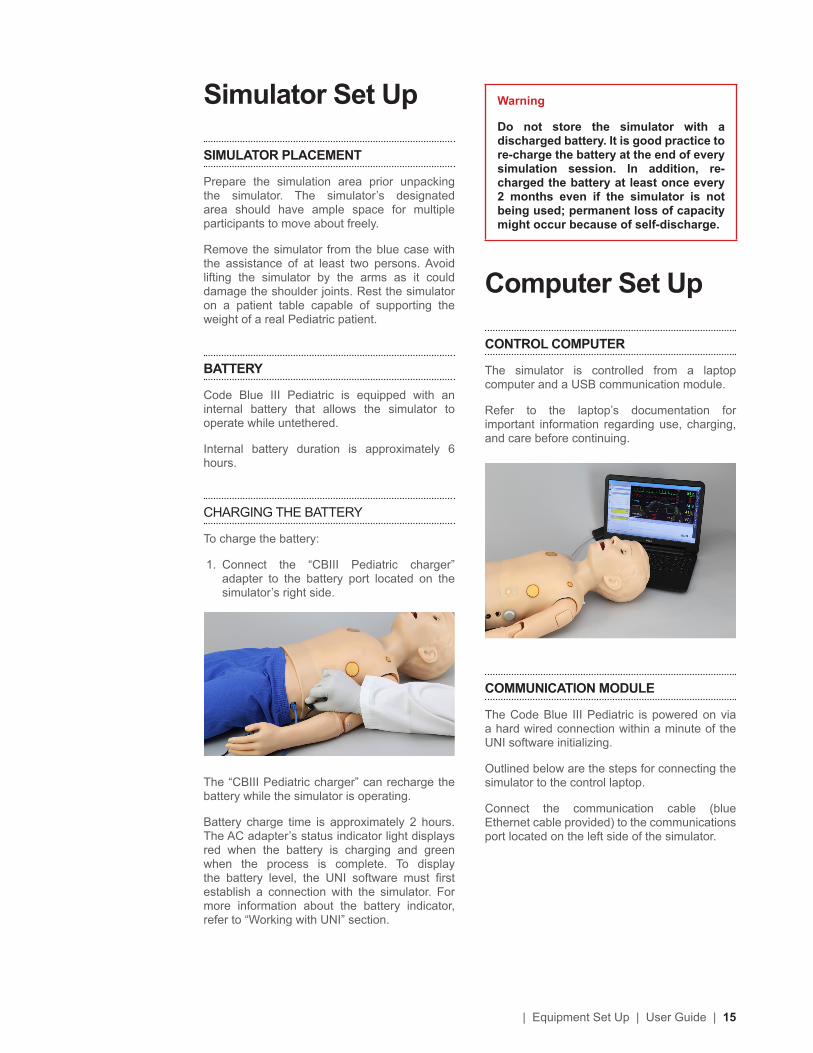
1. Connect the “CBIII Pediatric charger” adapter to the battery port located on the simulator’s right side.
The “CBIII Pediatric charger” can recharge the battery while the simulator is operating.
Battery charge time is approximately 2 hours. The AC adapter’s status indicator light displays red when the battery is charging and green when the process is complete. To display the battery level, the UNI software must first establish a connection with the simulator. For more information about the battery indicator, refer to “Working with UNI” section.
Warning
Do not store the simulator with a discharged battery. It is good practice to re-charge the battery at the end of every simulation session. In addition, re-charged the battery at least once every 2 months even if the simulator is not being used; permanent loss of capacity might occur because of self-discharge.
Computer Set Up
CONTROL COMPUTER
The simulator is controlled from a laptop computer and a USB communication module.
Refer to the laptop’s documentation for important information regarding use, charging, and care before continuing.
COMMUNICATION MODULE
The Code Blue III Pediatric is powered on via a hard wired connection within a minute of the UNI software initializing.
Outlined below are the steps for connecting the simulator to the control laptop.
Connect the communication cable (blue Ethernet cable provided) to the communications port located on the left side of the simulator.
16 | User Guide | Equipment Set Up |
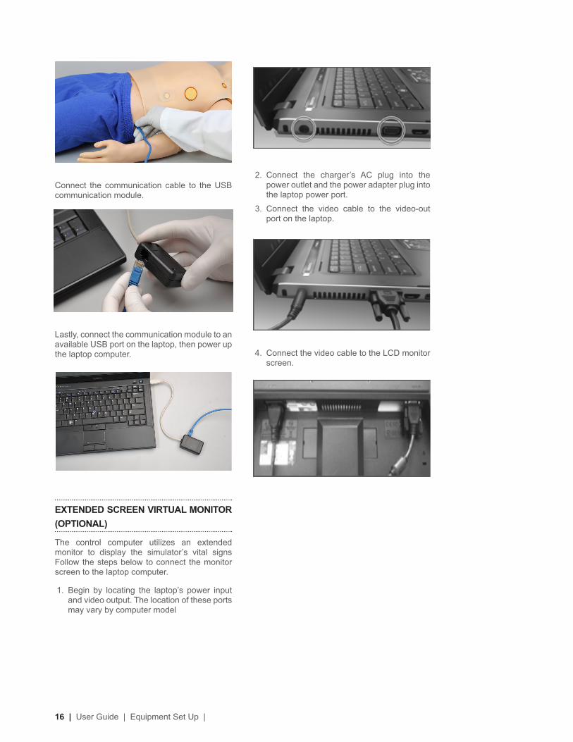
2. Connect the charger’s AC plug into the power outlet and the power adapter plug into the laptop power port.
3. Connect the video cable to the video-out port on the laptop.
4. Connect the video cable to the LCD monitor screen.
Connect the communication cable to the USB communication module.
Lastly, connect the communication module to an available USB port on the laptop, then power up the laptop computer.
EXTENDED SCREEN VIRTUAL MONITOR (OPTIONAL)
The control computer utilizes an extended monitor to display the simulator’s vital signs Follow the steps below to connect the monitor screen to the laptop computer.
1. Begin by locating the laptop’s power input and video output. The location of these ports may vary by computer model
| Equipment Set Up | User Guide | 17
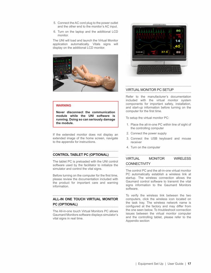
VIRTUAL MONITOR PC SETUP
Refer to the manufacturer’s documentation included with the virtual monitor system components for important safety, installation, and start-up information before turning on the computer for the first time.
To setup the virtual monitor PC:
1. Place the all-in-one PC within line of sight of the controlling computer
2. Connect the power supply
3. Connect the USB keyboard and mouse receiver
4. Turn on the computer
VIRTUAL MONITOR WIRELESS CONNECTIVITY
The control PC and the all-in-one virtual monitor PC automatically establish a wireless link at startup. The wireless connection allows the Gaumard control software to transmit the vital signs information to the Gaumard Monitors software.
To verify the wireless link between the two computers, click the wireless icon located on the task tray. The wireless network name is configured at the factory and may differ from the one seen below. To troubleshoot connection issues between the virtual monitor computer and the controlling tablet, please refer to the Appendix section
5. Connect the AC cord plug to the power outlet and the other end to the monitor’s AC input.
6. Turn on the laptop and the additional LCD monitor.
The UNI will load and launch the Virtual Monitor application automatically. Vitals signs will display on the additional LCD monitor.
WARNING
Never disconnect the communication module while the UNI software is running. Doing so can seriously damage the module.
If the extended monitor does not display an extended image of the home screen, navigate to the appendix for instructions.
CONTROL TABLET PC (OPTIONAL)
The tablet PC is preloaded with the UNI control software used by the facilitator to initialize the simulator and control the vital signs.
Before turning on the computer for the first time, please review the documentation included with the product for important care and warning information.
ALL-IN ONE TOUCH VIRTUAL MONITOR PC (OPTIONAL)
The All-in-one touch Virtual Monitors PC allows Gaumard Monitors software displays simulator’s vital signs in real time.
18 | User Guide | Equipment Set Up |
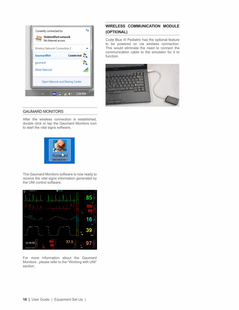
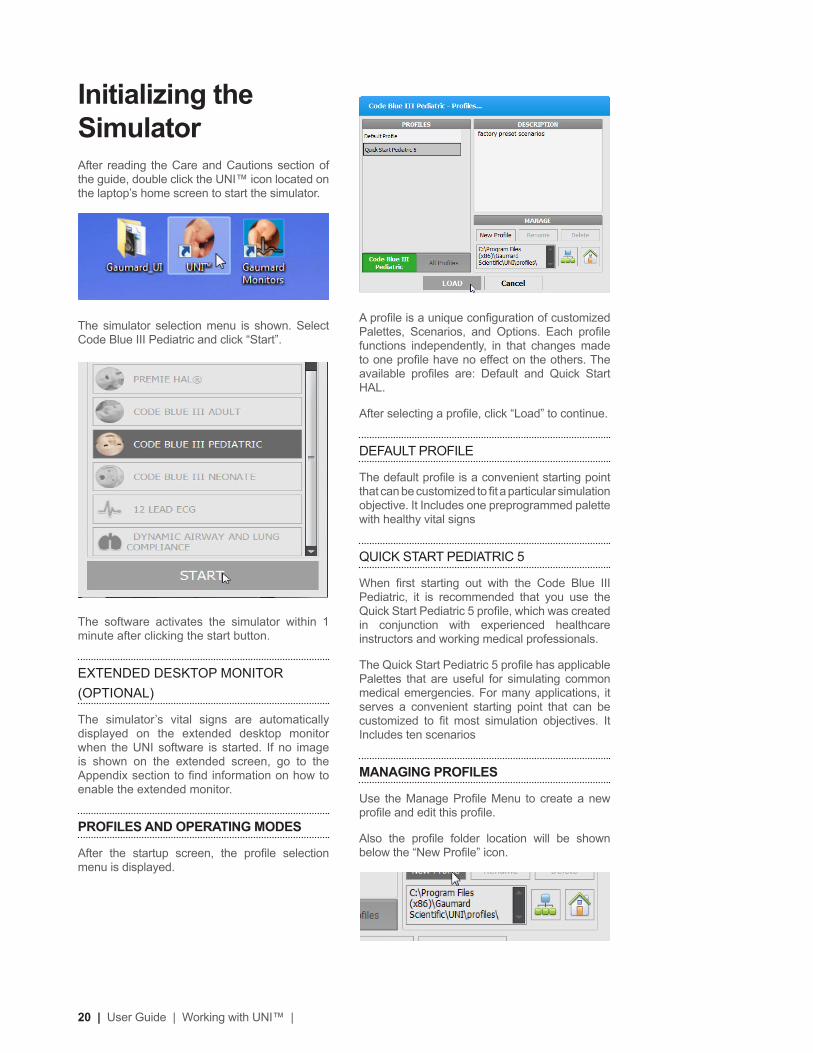
WIRELESS COMMUNICATION MODULE (OPTIONAL)
Code Blue III Pediatric has the optional feature to be powered on via wireless connection. This would eliminate the need to connect the communication cable to the simulator for it to function.
GAUMARD MONITORS
After the wireless connection is established, double click or tap the Gaumard Monitors icon to start the vital signs software.
The Gaumard Monitors software is now ready to receive the vital signs information generated by the UNI control software.
For more information about the Gaumard Monitors , please refer to the “Working with UNI” section.

| Working with UNI™ | User Guide | 19
Working with UNI™
20 | User Guide | Working with UNI™ |
Initializing the SimulatorAfter reading the Care and Cautions section of the guide, double click the UNI™ icon located on the laptop’s home screen to start the simulator.
The simulator selection menu is shown. Select Code Blue III Pediatric and click “Start”.
The software activates the simulator within 1 minute after clicking the start button.
EXTENDED DESKTOP MONITOR (OPTIONAL)
The simulator’s vital signs are automatically displayed on the extended desktop monitor when the UNI software is started. If no image is shown on the extended screen, go to the Appendix section to find information on how to enable the extended monitor.
PROFILES AND OPERATING MODES
After the startup screen, the profile selection menu is displayed.
A profile is a unique configuration of customized Palettes, Scenarios, and Options. Each profile functions independently, in that changes made to one profile have no effect on the others. The available profiles are: Default and Quick Start HAL.
After selecting a profile, click “Load” to continue.
DEFAULT PROFILE
The default profile is a convenient starting point that can be customized to fit a particular simulation objective. It Includes one preprogrammed palette with healthy vital signs
QUICK START PEDIATRIC 5
When first starting out with the Code Blue III Pediatric, it is recommended that you use the Quick Start Pediatric 5 profile, which was created in conjunction with experienced healthcare instructors and working medical professionals.
The Quick Start Pediatric 5 profile has applicable Palettes that are useful for simulating common medical emergencies. For many applications, it serves a convenient starting point that can be customized to fit most simulation objectives. It Includes ten scenarios
MANAGING PROFILES
Use the Manage Profile Menu to create a new profile and edit this profile.
Also the profile folder location will be shown below the “New Profile” icon.
| Working with UNI™ | User Guide | 21
Use the “Map Profiles folder“ icon to select the location of the new profile to be created on the server.
Select the server location and click “Make New Folder” to create the profile folder.
Assign a name to the folder and click “OK”
The new profile folder location will show up. Then proceed to create a new profile, see instructions detailed below.
Use the “Home” icon to reset to default profiles folder.
CREATING A NEW PROFILE
Profiles store palette, scenario, and option settings independently; changes made to one profile have no effect on the others. Below are some examples on how profiles are used.
• Assign one profile to each user of your Gaumard simulator system
• Use profiles to organize and protect palettes and scenarios
• Create a profile dedicated to a specific academic course taught by multiple instructors
• Devote an entire profile to one particular subject area, or even one particular scenario
To create a new profile, click “New Profile”.
Enter a name for the new profile followed by a description.
Enable the PIN protection to prevent unauthorized users from accessing or making changes to this profile.
Lastly, click “Create” to save the new profile.
Click “Rename” or “Delete” to change the name of delete this new profile
22 | User Guide | Working with UNI™ |
CONNECTION STATUS
Full bars indicate excellent communication between the computer and the simulator (i.e., normal operation).
The indicator is clear when no attempts to communicate with the simulator are being made; for example when the communication module is not connected to the computer.
BATTERY INDICATOR
The battery status indicator progresses as the battery in the simulator is used. The exclamation mark indicator is shown when there is no communication and battery information cannot be retrieved.
When the battery icon is depleted, the simulator is set to STAND-BY mode automatically to protect some of the simulator’s internal components. Simulator will not initialize until connected to the charger or the battery is replaced with a fully charged spare.
Internal battery duration is approximately 6 hours
When the battery icon is depleted, the simulator is set to STAND-BY mode automatically to protect some of the simulator’s internal components. Simulator will not initialize until connected to the charger or the battery is replaced with a fully charged spare.
AIR RESERVOIR
The air reservoir indicator shows the percentage of pressurized air held in the system’s internal reservoir.
Filling the reservoir will enable the pulses and the breathing for a brief time.
To fill the reservoir refer to the “Working with the Simulator” section.
SESSION CLOCK
The session timer allows the facilitator to maintain a chronological record for individual simulation sessions. The session timer can be reset from the file menu when a new simulation session begins, or by clicking the session time icon and then Reset Session Clock. Events
UNI™ InterfaceThe UNI software is used control the simulator, monitor the vital signs, and evaluate the provider’s performance. The simulation technician or instructor carrying out the simulation operates the UNI software.
| Working with UNI™ | User Guide | 23
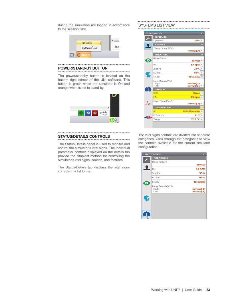
SYSTEMS LIST VIEW
The vital signs controls are divided into separate categories. Click through the categories to view the controls available for the current simulator configuration.
during the simulation are logged in accordance to the session time.
POWER/STAND-BY BUTTON
The power/standby button is located on the bottom right corner of the UNI software. This button is green when the simulator is On and orange when is set to stand-by.
STATUS/DETAILS CONTROLS
The Status/Details panel is used to monitor and control the simulator’s vital signs. The individual parameter controls displayed on the details tab provide the simplest method for controlling the simulator’s vital signs, sounds, and features.
The Status/Details tab displays the vital signs controls in a list format.
24 | User Guide | Working with UNI™ |
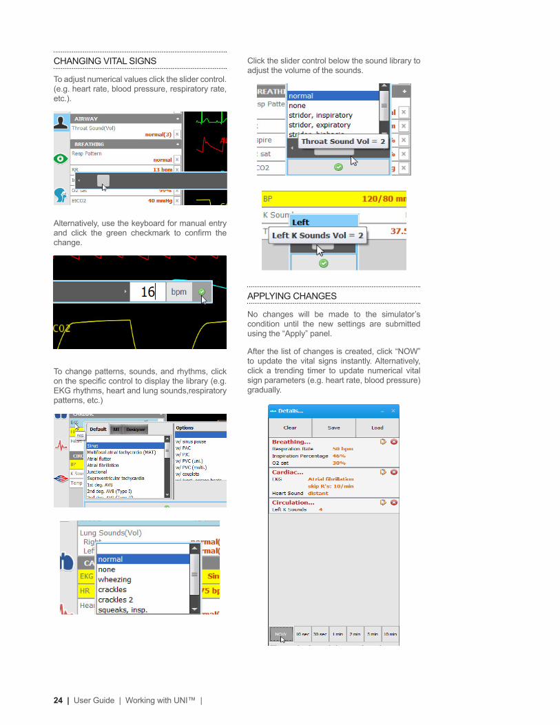
Click the slider control below the sound library to adjust the volume of the sounds.
APPLYING CHANGES
No changes will be made to the simulator’s condition until the new settings are submitted using the “Apply” panel.
After the list of changes is created, click “NOW” to update the vital signs instantly. Alternatively, click a trending timer to update numerical vital sign parameters (e.g. heart rate, blood pressure) gradually.
CHANGING VITAL SIGNS
To adjust numerical values click the slider control. (e.g. heart rate, blood pressure, respiratory rate, etc.).
Alternatively, use the keyboard for manual entry and click the green checkmark to confirm the change.
To change patterns, sounds, and rhythms, click on the specific control to display the library (e.g. EKG rhythms, heart and lung sounds,respiratory patterns, etc.)
| Working with UNI™ | User Guide | 25
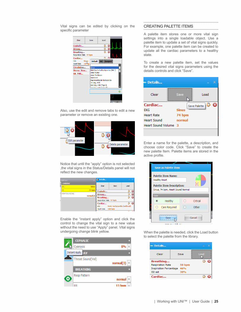
CREATING PALETTE ITEMS
A palette item stores one or more vital sign settings into a single loadable object. Use a palette item to update a set of vital signs quickly. For example, one palette item can be created to update all the cardiac parameters to a healthy state.
To create a new palette item, set the values for the desired vital signs parameters using the details controls and click “Save”.
Enter a name for the palette, a description, and choose color code. Click “Save” to create the new palette Item. Palette items are stored in the active profile.
When the palette is needed, click the Load button to select the palette from the library.
Vital signs can be edited by clicking on the specific parameter
Also, use the edit and remove tabs to edit a new parameter or remove an existing one.
Notice that until the “apply” option is not selected ,the vital signs in the Status/Details panel will not reflect the new changes.
Enable the “instant apply” option and click the control to change the vital sign to a new value without the need to use “Apply” panel. Vital signs undergoing change blink yellow.
26 | User Guide | Working with UNI™ |
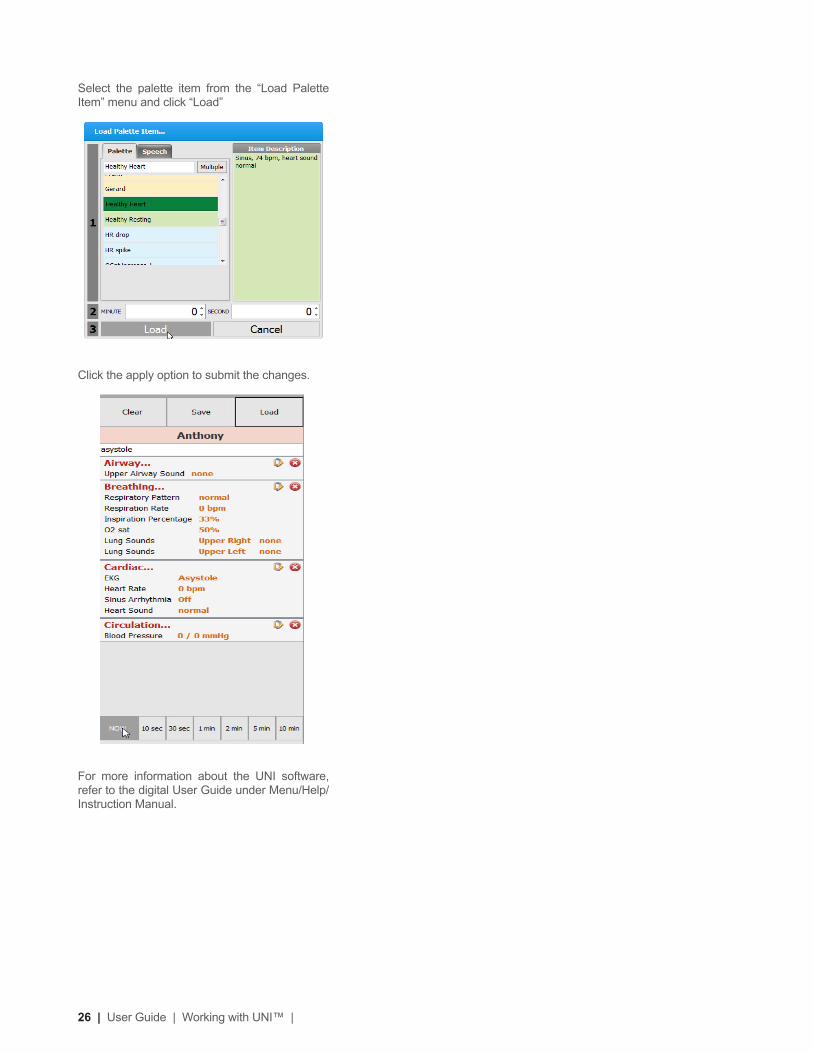
Select the palette item from the “Load Palette Item” menu and click “Load”
Click the apply option to submit the changes.
For more information about the UNI software, refer to the digital User Guide under Menu/Help/Instruction Manual.

| Working with Code Blue® III Pediatric | User Guide | 27
Working with Code Blue® III Pediatric
28 | User Guide | Working with Code Blue® III Pediatric |
Airway
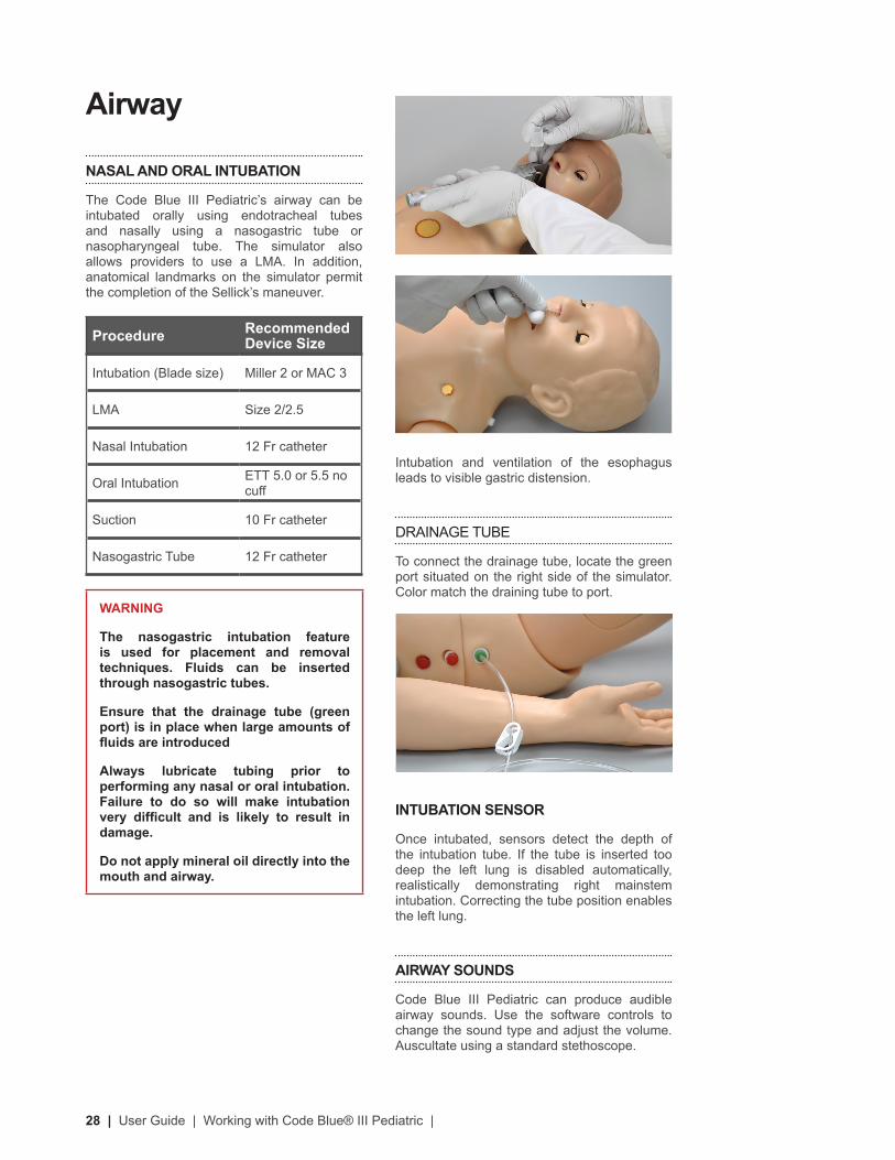
NASAL AND ORAL INTUBATION
The Code Blue III Pediatric’s airway can be intubated orally using endotracheal tubes and nasally using a nasogastric tube or nasopharyngeal tube. The simulator also allows providers to use a LMA. In addition, anatomical landmarks on the simulator permit the completion of the Sellick’s maneuver.
Procedure Recommended Device Size
Intubation (Blade size) Miller 2 or MAC 3
LMA Size 2/2.5
Nasal Intubation 12 Fr catheter
Oral Intubation ETT 5.0 or 5.5 no cuff
Suction 10 Fr catheter
Nasogastric Tube 12 Fr catheter
WARNING
The nasogastric intubation feature is used for placement and removal techniques. Fluids can be inserted through nasogastric tubes.
Ensure that the drainage tube (green port) is in place when large amounts of fluids are introduced
Always lubricate tubing prior to performing any nasal or oral intubation. Failure to do so will make intubation very difficult and is likely to result in damage.
Do not apply mineral oil directly into the mouth and airway.
Intubation and ventilation of the esophagus leads to visible gastric distension.
DRAINAGE TUBE
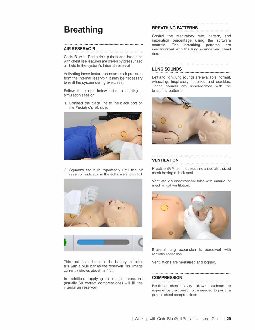
To connect the drainage tube, locate the green port situated on the right side of the simulator. Color match the draining tube to port.
INTUBATION SENSOR
Once intubated, sensors detect the depth of the intubation tube. If the tube is inserted too deep the left lung is disabled automatically, realistically demonstrating right mainstem intubation. Correcting the tube position enables the left lung.
AIRWAY SOUNDS
Code Blue III Pediatric can produce audible airway sounds. Use the software controls to change the sound type and adjust the volume. Auscultate using a standard stethoscope.
| Working with Code Blue® III Pediatric | User Guide | 29
Breathing
AIR RESERVOIR
Code Blue III Pediatric’s pulses and breathing with chest rise features are driven by pressurized air held in the system’s internal reservoir.
Activating these features consumes air pressure from the internal reservoir. It may be necessary to refill the system during exercises.
Follow the steps below prior to starting a simulation session:
1. Connect the black line to the black port on the Pediatric’s left side.
2. Squeeze the bulb repeatedly until the air reservoir indicator in the software shows full
This tool located next to the battery indicator fills with a blue bar as the reservoir fills. Image currently shows about half full.
In addition, applying chest compressions (usually 60 correct compressions) will fill the internal air reservoir
BREATHING PATTERNS
Control the respiratory rate, pattern, and inspiration percentage using the software controls. The breathing patterns are synchronized with the lung sounds and chest rise.
LUNG SOUNDS
Left and right lung sounds are available: normal, wheezing, inspiratory squeaks, and crackles. These sounds are synchronized with the breathing patterns.
VENTILATION
Practice BVM techniques using a pediatric sized mask having a thick seal.
Ventilate via endotracheal tube with manual or mechanical ventilation.
Bilateral lung expansion is perceived with realistic chest rise.
Ventilations are measured and logged.
COMPRESSION
Realistic chest cavity allows students to experience the correct force needed to perform proper chest compressions.
30 | User Guide | Working with Code Blue® III Pediatric |
Depth of chest compressions are measured and logged in cm or inches.
Proper chest compressions during CPR result in palpable carotid and femoral pulses.
Cardiac
HEART SOUNDS
Code Blue III Pediatric is equipped with realistic heart sounds (normal, distant, systolic murmur, S3 and S4) which are tied to a user defined heart rate and selectable rhythms
ECG MONITORING
One of Code Blue III Pediatric’s most exciting features is the accommodation of real ECG monitoring. In most cases, no special instruction is necessary to use such devices. The Pediatric’s conductive skin sites allow the attachment of real ECG electrodes. This feature permits the user to track cardiac rhythms with their own equipment just like with a human patient.
INSTRUCTIONS FOR USE
1. Turn on the simulator. Refer to the Equipment Set-Up section.
2. Connect the ECG lead wires on the Pediatric’s ECG sites.
3. Turn on the ECG monitor.
ELECTRICAL THERAPY
Code Blue III Pediatric conductive skin sites allow the attachment of real ECG electrodes. This feature permits the user to track cardiac rhythms with their own equipment just like with a human patient.
Defibrillation is only allowed on the large sternum and apex sites, circled GREEN below. NEVER deliver a shock to ECG electrode targets on the shoulders or waist, marked RED below. Doing so will not create a fire hazard, nor is there risk of shock to the provider, but internal damage in Code Blue III Pediatric may result. This situation is considered improper use and is NOT covered by the Code Blue III warranty.
| Working with Code Blue® III Pediatric | User Guide | 31
Feature Maximum
Defibrillation 150 Jules
The snap sites provide the same electrical therapy functionality as the gold patches. This includes a detectable heart rhythm, cardioversion, pacing, and the detection of electrical therapy by the Gaumard software.
The snap connections are only functional when the internal “Defibrillation snap harness” is installed between the ECG module connector and the chest skin connector.
When the “Defibrillation snap harness” is connected, the chest skin sternum and apex gold patches are disabled.
The sternum and apex gold patches on Code Blue III Pediatric’s chest skin are connected as a standard.
To install the defibrillation snaps and enable snap sites follow the instructions.
1. Turn off the simulator.
2. Unscrew and remove the silver knobs at the Pediatric’s waist.
3. Carefully remove the chest skin on the manikin’s left side by detaching the skin from the back and pulling it up as seen below.
There are inherent dangers in the use of some medical devices. For simulations that incorporate electrical therapy of any kind, always know your equipment, and follow the device manufacturers’ safety guidelines.
SNAP CONNECTORS
The chest skin Apex Snap connectors and “Snap Adapter Cable” allow providers to deliver electrical therapy at the sternum and apex sites without the use and frequent replacement of pads or patches.
Sternum Snap
Apex Snap
INSTRUCTIONS FOR USE
1. Turn on the simulator. Refer to the Equipment Set-Up section.
2. Connect the ECG lead wires on the Pediatric’s ECG sites.
3. Turn on the ECG monitor.
ELECTRICAL THERAPY
Code Blue III Pediatric conductive skin sites allow the attachment of real ECG electrodes. This feature permits the user to track cardiac rhythms with their own equipment just like with a human patient.
Defibrillation is only allowed on the large sternum and apex sites, circled GREEN below. NEVER deliver a shock to ECG electrode targets on the shoulders or waist, marked RED below. Doing so will not create a fire hazard, nor is there risk of shock to the provider, but internal damage in Code Blue III Pediatric may result. This situation is considered improper use and is NOT covered by the Code Blue III warranty.
32 | User Guide | Working with Code Blue® III Pediatric |
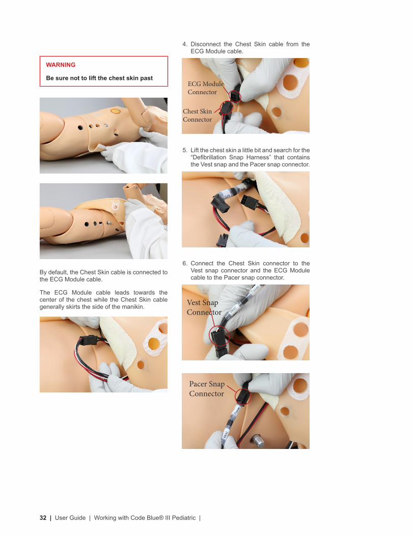
4. Disconnect the Chest Skin cable from the ECG Module cable.
5. Lift the chest skin a little bit and search for the “Defibrillation Snap Harness” that contains the Vest snap and the Pacer snap connector.
6. Connect the Chest Skin connector to the Vest snap connector and the ECG Module cable to the Pacer snap connector.
WARNING
Be sure not to lift the chest skin past
By default, the Chest Skin cable is connected to the ECG Module cable.
The ECG Module cable leads towards the center of the chest while the Chest Skin cable generally skirts the side of the manikin. Vest Snap
Connector
Pacer Snap Connector
Chest Skin Connector
ECG Module Connector
| Working with Code Blue® III Pediatric | User Guide | 33
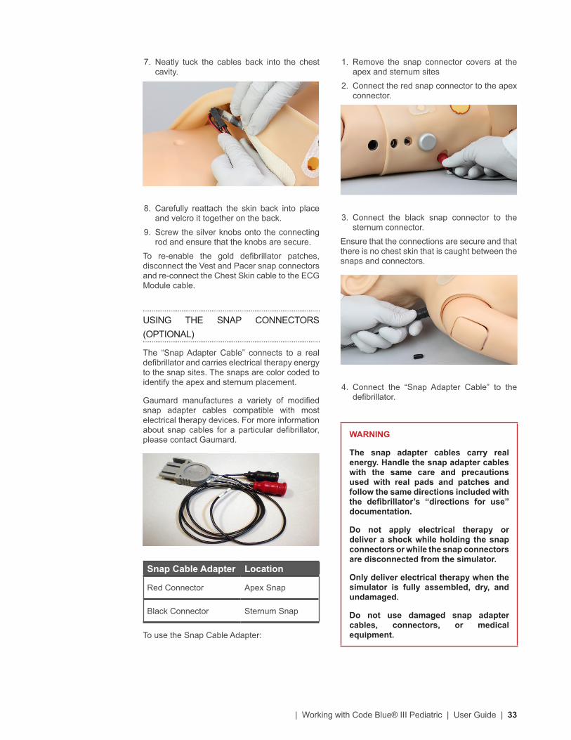
1. Remove the snap connector covers at the apex and sternum sites
2. Connect the red snap connector to the apex connector.
3. Connect the black snap connector to the sternum connector.
Ensure that the connections are secure and that there is no chest skin that is caught between the snaps and connectors.
4. Connect the “Snap Adapter Cable” to the defibrillator.
WARNING
The snap adapter cables carry real energy. Handle the snap adapter cables with the same care and precautions used with real pads and patches and follow the same directions included with the defibrillator’s “directions for use” documentation.
Do not apply electrical therapy or deliver a shock while holding the snap connectors or while the snap connectors are disconnected from the simulator.
Only deliver electrical therapy when the simulator is fully assembled, dry, and undamaged.
Do not use damaged snap adapter cables, connectors, or medical equipment.
7. Neatly tuck the cables back into the chest cavity.
8. Carefully reattach the skin back into place and velcro it together on the back.
9. Screw the silver knobs onto the connecting rod and ensure that the knobs are secure.
To re-enable the gold defibrillator patches, disconnect the Vest and Pacer snap connectors and re-connect the Chest Skin cable to the ECG Module cable.
USING THE SNAP CONNECTORS (OPTIONAL)
The “Snap Adapter Cable” connects to a real defibrillator and carries electrical therapy energy to the snap sites. The snaps are color coded to identify the apex and sternum placement.
Gaumard manufactures a variety of modified snap adapter cables compatible with most electrical therapy devices. For more information about snap cables for a particular defibrillator, please contact Gaumard.
Snap Cable Adapter Location
Red Connector Apex Snap
Black Connector Sternum Snap
To use the Snap Cable Adapter:
34 | User Guide | Working with Code Blue® III Pediatric |
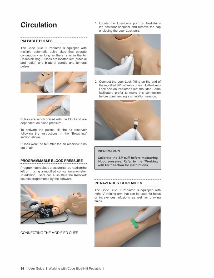
1. Locate the Luer-Lock port on Pediatric’s left posterior shoulder and remove the cap enclosing the Luer-Lock port.
2. Connect the Luer-Lock fitting on the end of the modified BP cuff extra branch to the Luer-Lock port on Pediatric’s left shoulder. Some facilitators prefer to make this connection before commencing a simulation session.
INFORMATION
Calibrate the BP cuff before measuring blood pressure. Refer to the “Working with UNI” section for instructions.
INTRAVENOUS EXTREMITIES
The Code Blue III Pediatric is equipped with right IV training arm that can be used for bolus or intravenous infusions as well as drawing fluids.
Circulation
PALPABLE PULSES
The Code Blue III Pediatric is equipped with multiple automatic pulse sites that operate continuously as long as there is air in the Air Reservoir Bag. Pulses are located left (brachial and radial) and bilateral carotid and femoral pulses.
Pulses are synchronized with the ECG and are dependent on blood pressure.
To activate the pulses, fill the air reservoir following the instructions in the “Breathing” section above.
Pulses won’t be felt after the air reservoir runs out of air.
PROGRAMMABLE BLOOD PRESSURE
Programmable blood pressure can be read on the left arm using a modified sphygmomanometer. In addition, users can auscultate the Korotkoff sounds programmed by the software.
CONNECTING THE MODIFIED CUFF
| Working with Code Blue® III Pediatric | User Guide | 35
Pull the plunger to create suction, which will collapse the veins. Disconnect the syringe tube from the port on the torso while maintaining suction. The port will seal, and the veins will remain collapsed.
For simulation of high volume infusions, it is necessary to leave the drain tube attached to the simulator. Place the distal end of the tube in a suitable outlet or container.
After filling the vasculature, you can perform the following procedures:
• Intraosseous Access on the right leg
• IV Training on the right arm
WARNING
Do not attempt to fill IV system without the drain hose in place.
Always leave the drain hose connected when injecting fluids into the system.
Use only Gaumard’s provided simulated blood. Any other simulated blood brand containing sugar or any additive may cause blockage and/or interruption of the vasculature system.
FILLING THE VASCULATURE
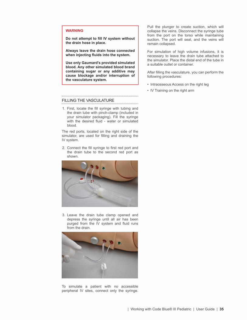
1. First, locate the fill syringe with tubing and the drain tube with pinch-clamp (included in your simulator packaging). Fill the syringe with the desired fluid - water or simulated blood.
The red ports, located on the right side of the simulator, are used for filling and draining the IV system.
2. Connect the fill syringe to first red port and the drain tube to the second red port as shown.
3. Leave the drain tube clamp opened and depress the syringe until all air has been purged from the IV system and fluid runs from the drain.
To simulate a patient with no accessible peripheral IV sites, connect only the syringe.
36 | User Guide | Working with Code Blue® III Pediatric |
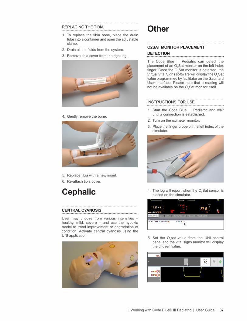
INTRAOSSEOUS ACCESS
I/O access is used for the infusion of fluids, blood and/or drugs directly into the bone marrow of the tibia or other large bone. Setting up an intraosseous access line is an invasive procedure that can be simulated with the Code Blue III Pediatric.
The following procedure describes how to use the I/O access feature:
1. Follow the instructions “Filling the vasculature” to fill the tibia bone with fluids.
2. Palpate tibial tuberosity.
3. Insert bone aspiration needle below tibial tuberosity. Note the sharp decrease in needle resistance as it passes into the bone marrow cavity. Remove stylet, aspirate bone marrow, and infuse fluids.
WARNING
Always drain and flush the reservoirs after every simulation.
Systemic
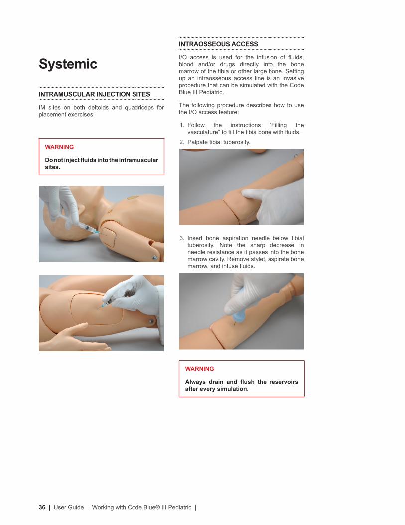
INTRAMUSCULAR INJECTION SITES
IM sites on both deltoids and quadriceps for placement exercises.
WARNING
Do not inject fluids into the intramuscular sites.
| Working with Code Blue® III Pediatric | User Guide | 37
Other
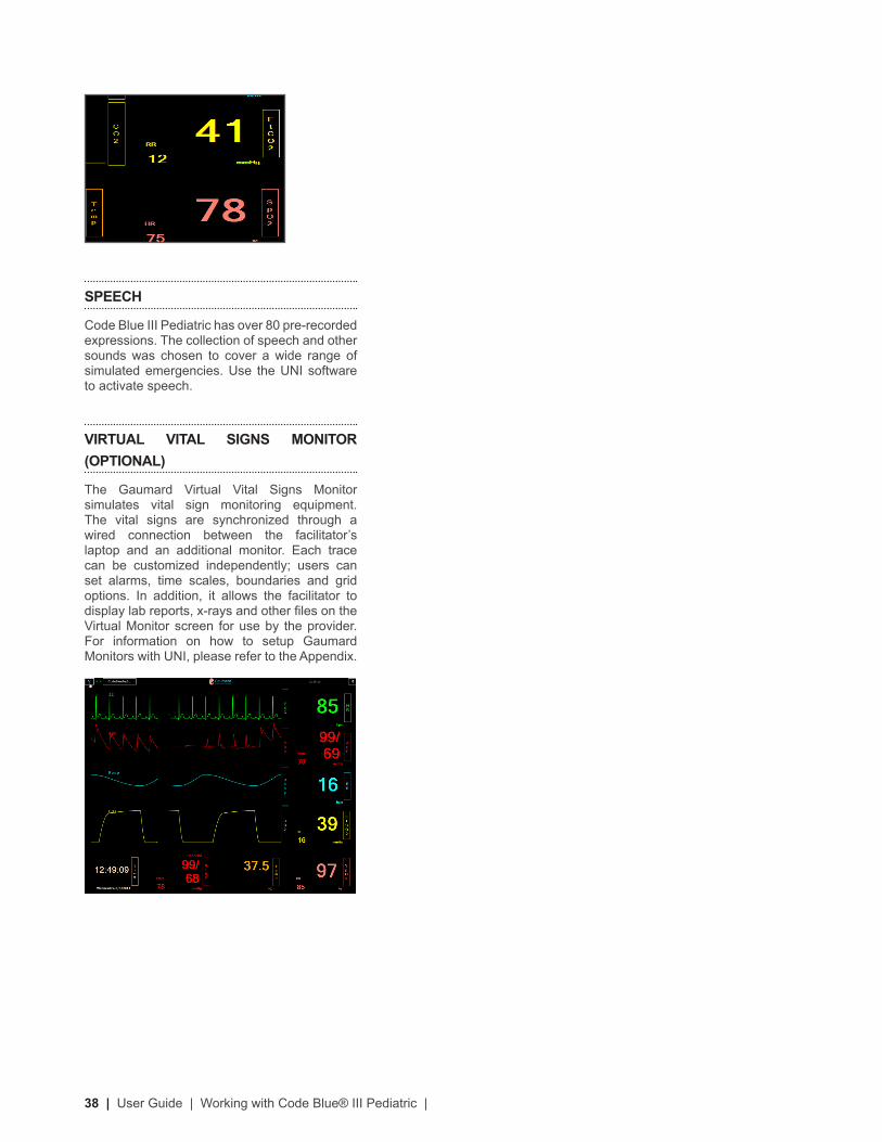
O2SAT MONITOR PLACEMENT DETECTION
The Code Blue III Pediatric can detect the placement of an O2Sat monitor on the left index finger. Once the O2Sat monitor is detected, the Virtual Vital Signs software will display the O2Sat value programmed by facilitator on the Gaumard User Interface. Please note that a reading will not be available on the O2Sat monitor itself.
INSTRUCTIONS FOR USE
1. Start the Code Blue III Pediatric and wait until a connection is established.
2. Turn on the oximeter monitor.
3. Place the finger probe on the left index of the simulator.
4. The log will report when the O2Sat sensor is placed on the simulator.
5. Set the O2sat value from the UNI control panel and the vital signs monitor will display the chosen value.
REPLACING THE TIBIA
1. To replace the tibia bone, place the drain tube into a container and open the adjustable clamp.
2. Drain all the fluids from the system.
3. Remove tibia cover from the right leg.
4. Gently remove the bone.
5. Replace tibia with a new insert.
6. Re-attach tibia cover.
Cephalic
CENTRAL CYANOSIS
User may choose from various intensities – healthy, mild, severe – and use the hypoxia model to trend improvement or degradation of condition. Activate central cyanosis using the UNI application.
38 | User Guide | Working with Code Blue® III Pediatric |
SPEECH
Code Blue III Pediatric has over 80 pre-recorded expressions. The collection of speech and other sounds was chosen to cover a wide range of simulated emergencies. Use the UNI software to activate speech.
VIRTUAL VITAL SIGNS MONITOR (OPTIONAL)
The Gaumard Virtual Vital Signs Monitor simulates vital sign monitoring equipment. The vital signs are synchronized through a wired connection between the facilitator’s laptop and an additional monitor. Each trace can be customized independently; users can set alarms, time scales, boundaries and grid options. In addition, it allows the facilitator to display lab reports, x-rays and other files on the Virtual Monitor screen for use by the provider. For information on how to setup Gaumard Monitors with UNI, please refer to the Appendix.

| Appendix | User Guide | 39
Appendix
40 | User Guide | Appendix |
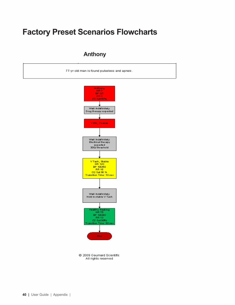
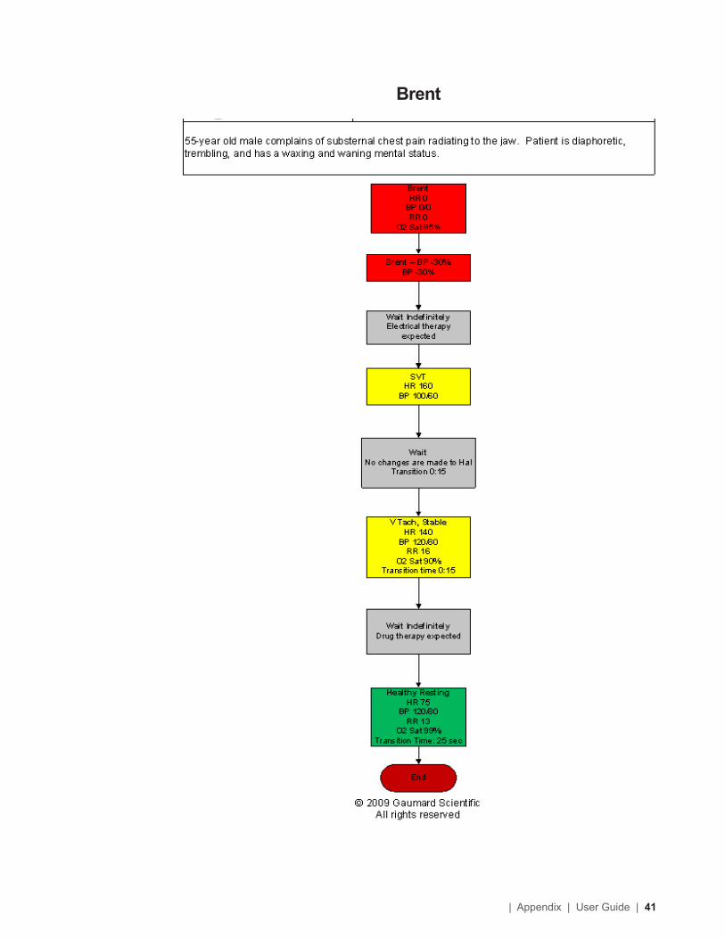
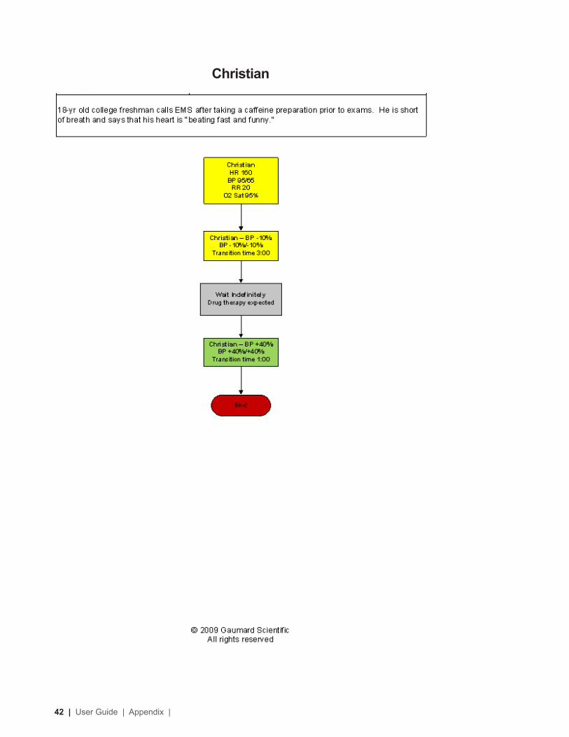
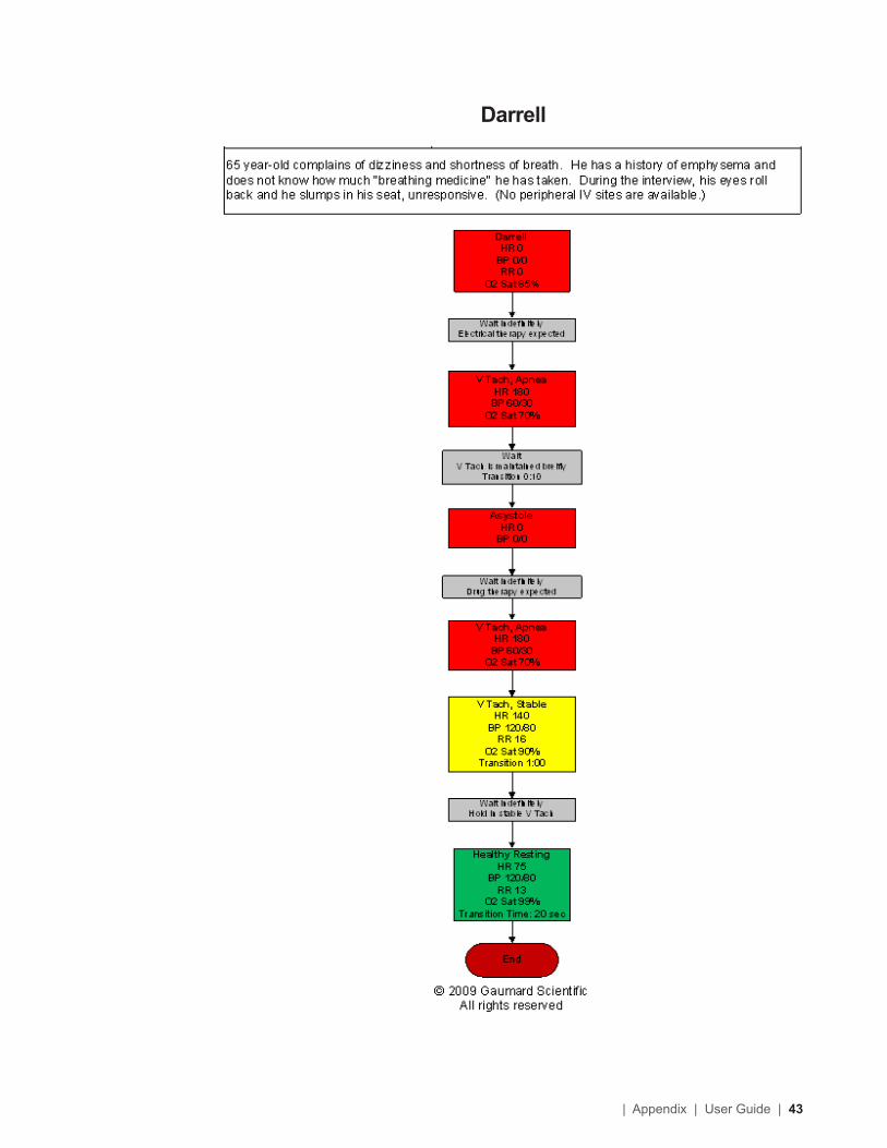
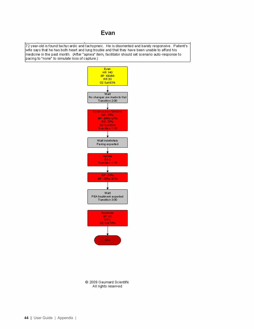
Anthony
Factory Preset Scenarios Flowcharts
| Appendix | User Guide | 41
Brent
42 | User Guide | Appendix |
Christian
| Appendix | User Guide | 43
Darrell
44 | User Guide | Appendix |
Evan
| Appendix | User Guide | 45
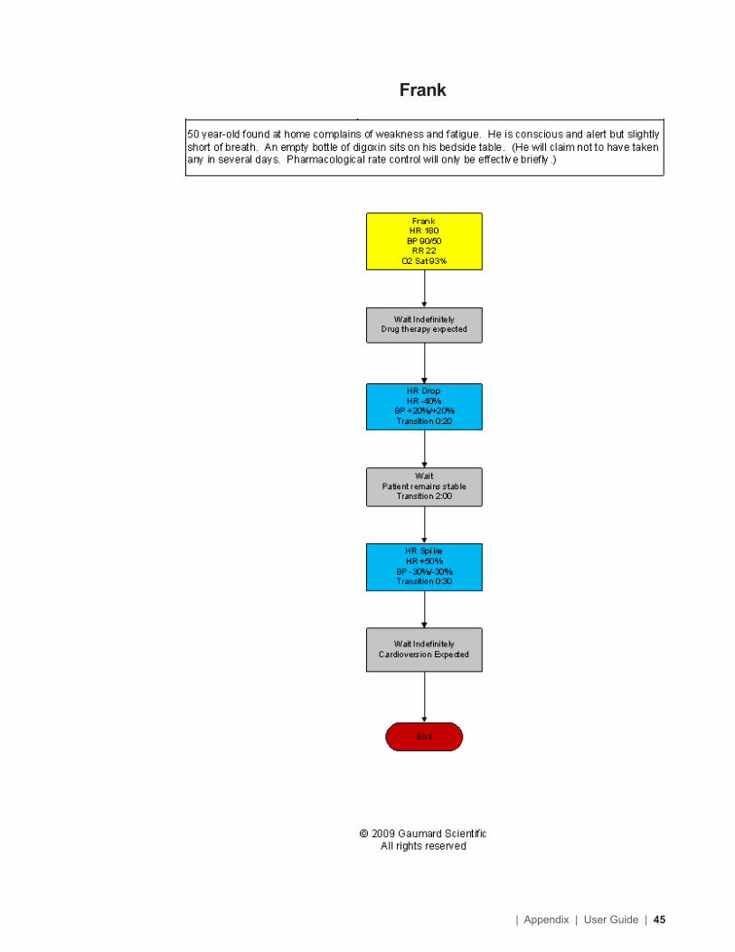
Frank
46 | User Guide | Appendix |
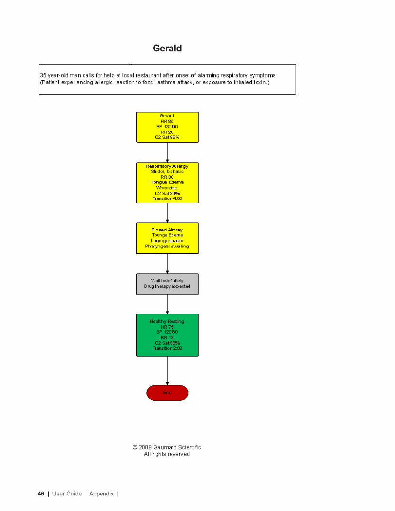
Gerald
| Appendix | User Guide | 47
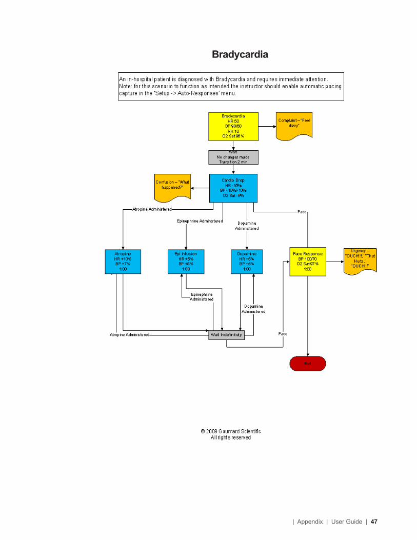
Bradycardia
48 | User Guide | Appendix |
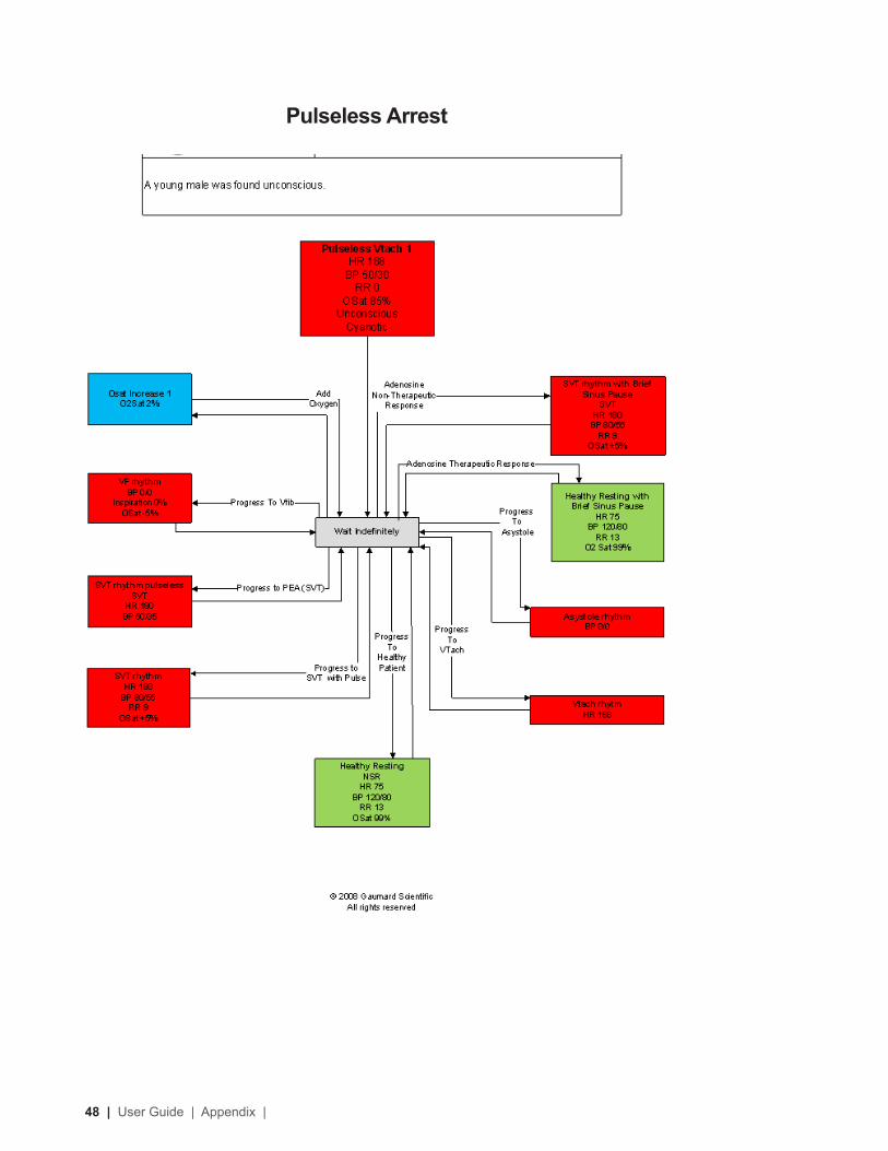
Pulseless Arrest
| Appendix | User Guide | 49
More about ScenariosTIPS ON CREATING SCENARIOS
THINKING IN TERMS OF PALETTE ITEMS
As described previously, palette items represent complete or partial groups of settings that have been stored as a single item. We learned how applying partial states will hold constant all settings that are left unspecified.
Not only does it take time to customize the palette, but a very large palette also becomes difficult to navigate. So, it is desirable to minimize the number of palette Items in each profile. To accomplish this, an experienced facilitator tries to create items that are as generally applicable as possible and can, thus, be applied to a wide range of scenarios. The key is to only include in your palette Items the settings that are directly related to the physiological event represented by that palette Item.
SMART SCENARIOS
After reading the Details, Palette, and Scenarios sections of this guide, it should be clear how to build a scenario. You may have already tried building your own or modifying some of the factory presets. The following four guidelines will refine your ability to build the best possible scenarios.
HOW WILL THE SCENARIO BEGIN?
The first thing to consider is the initial condition of the patient. Create a Palette Item to describe this condition. Make sure that this first step in the scenario is a complete state, indicate some selection for each and every available setting on the Details page. Remember that only the settings you specify will cause a change in Code Blue III Pediatric, and all other settings will remain constant. So, by starting with a complete state, Code Blue III Pediatric condition will always be the same when the scenario starts, regardless of what he was doing previously.
Likewise, the “transition duration” of the first step in the scenario should be zero, indicating that changes are applied immediately.
INCLUDE NOTES TO GUIDE THE FACILITATOR DURING THE SIMULATION.
It is common for scenario designers, especially those who act as facilitators, to neglect the importance of notes in the scenario. They think that they will remember the learning objectives, patient history, and other details at the time they are ready to conduct the simulation. They usually don’t, especially when revisiting a scenario months after creating it.
When you add “Wait” and “Wait Indefinitely” steps to a scenario, you have an opportunity to edit the item description. Use this description field to hold notes to the facilitator. Typically, scenario designers write notes in that space to indicate what the provider(s) or facilitator should be doing at that point.
Further, when saving the scenario, you may edit the scenario description. This is the best place to put patient history and any other longer notes and instructions.
ASSUME THAT PROVIDERS WILL DO THE RIGHT THING.
Usually, you should create a scenario with the assumption that the providers will perform correctly. As long as they do, the scenario can be allowed to continue.
Naturally, you must be prepared for what might happen to Code Blue III Pediatric when providers deviate from expectations. The consequences of such deviations can sometimes be included in the scenario, punctuated by “Wait Indefinitely” items. In other cases, the simulation will require more direct control by the facilitator via either the Palette or Details page. Ultimately you can use the branching scenario feature to make scenarios with more than one path.
CHOOSE AUTO-RESPONSE SETTINGS BASED ON THE SCENARIO CONTENT AND THE OBJECTIVES.
As you’ve seen, auto-responses can be used to free the facilitator’s attention. They also enhance realism by presenting instant reactions to the care providers. On the other hand, sometimes it is not possible or desirable to determine the responses before the simulation begins. Different environments and applications call for different settings.
50 | User Guide | Appendix |
Some teaching practices are best done with the auto-response settings in Prompt mode. Responses must be triggered by a vigilant facilitator. Though it is slower and requires more attention, the benefit of Prompt over other modes is that the simulation can be allowed to go in any direction, and it will be possible to choose the response on a case-by-case basis.
Other learning exercises require a higher degree of automation. For such applications, most facilitators choose Auto mode for the auto-response settings. The key issue is standardized timing of symptom presentation. A consistent, repeatable simulation is essential for fair assessment of that care provider in relation to others and for the broader interpretation of results in the context of training validation studies.
When in doubt, it is best to choose Prompt mode, in which the facilitator will be given direct control of the responses as events are detected.
| Appendix | User Guide | 51
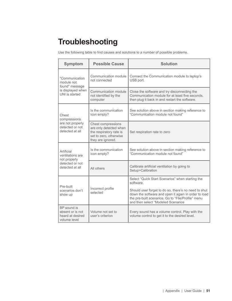
TroubleshootingUse the following table to find causes and solutions to a number of possible problems.
Symptom Possible Cause Solution
"Communication module not found" message is displayed when UNI is started
Communication module not connected
Connect the Communication module to laptop’s USB port.
Communication module not identified by the computer
Close the software and try disconnecting the Communication module for at least five seconds, then plug it back in and restart the software.
Chest compressions are not properly detected or not detected at all
Is the communication icon empty?
See solution above in section making reference to “Communication module not found”
Chest compressions are only detected when the respiratory rate is set to zero, otherwise they are ignored.
Set respiration rate to zero
Artificial ventilations are not properly detected or not detected at all
Is the communication icon empty?
See solution above in section making reference to “Communication module not found”
All others Calibrate artificial ventilation by going to Setup>Calibration
Pre-built scenarios don’t show up
Incorrect profile selected
Select “Quick Start Scenarios” when starting the software.
Should user forget to do so, there’s no need to shut down the software and open it again in order to load the pre-built scenarios. Go to “File/Profile” menu and then select “Modeled Scenarios
BP sound is absent or is not heard at desired volume level
Volume not set to user’s criterion
Every sound has a volume control. Play with the volume control to get it to the desired level.
52 | User Guide | Appendix |
DiagnosticsThe diagnostics tool is used to test the status of the modules that control the simulator’s features and functions. On the menu bar, click Help>Diagnostics to open the Diagnostics window.
This window is very useful for troubleshooting because it gives the user feedback on all of the working modules inside the simulator.
To run a complete module test, click “Check All Modules”.
You can also check individual modules by clicking on the specific module you wish to check and then clicking on the “Check Single Module” button. The button will flash green when pressed.
Active modules report light blue, and inactive and not installed modules report black. If there is a specific module that fails to respond please contact Technical Support for advanced troubleshooting steps.
Connecting to the Gaumard MonitorsTo connect the virtual monitor to the UNI, you must have the laptop joined to the additional monitor, and you must properly the extended monitor. The section below describes in detail how to do both of these things.
ENABLING DUAL DISPLAY
The Code Blue III Pediatric system uses an extended screen to display the vital signs information. Enable the extended displays using the instructions below. Prior to configuring the extended displays, the monitor must be connected and powered on.
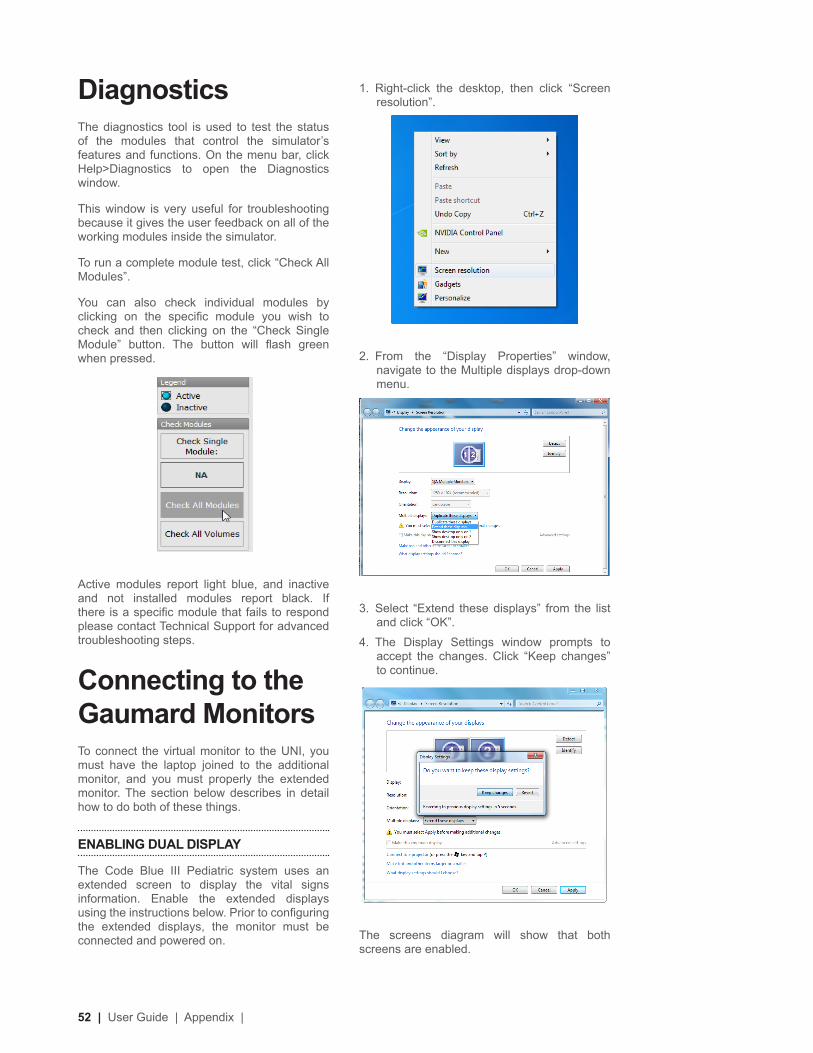
1. Right-click the desktop, then click “Screen resolution”.
2. From the “Display Properties” window, navigate to the Multiple displays drop-down menu.
3. Select “Extend these displays” from the list and click “OK”.
4. The Display Settings window prompts to accept the changes. Click “Keep changes” to continue.
The screens diagram will show that both screens are enabled.
| Appendix | User Guide | 53
5. Click “OK” to save changes.
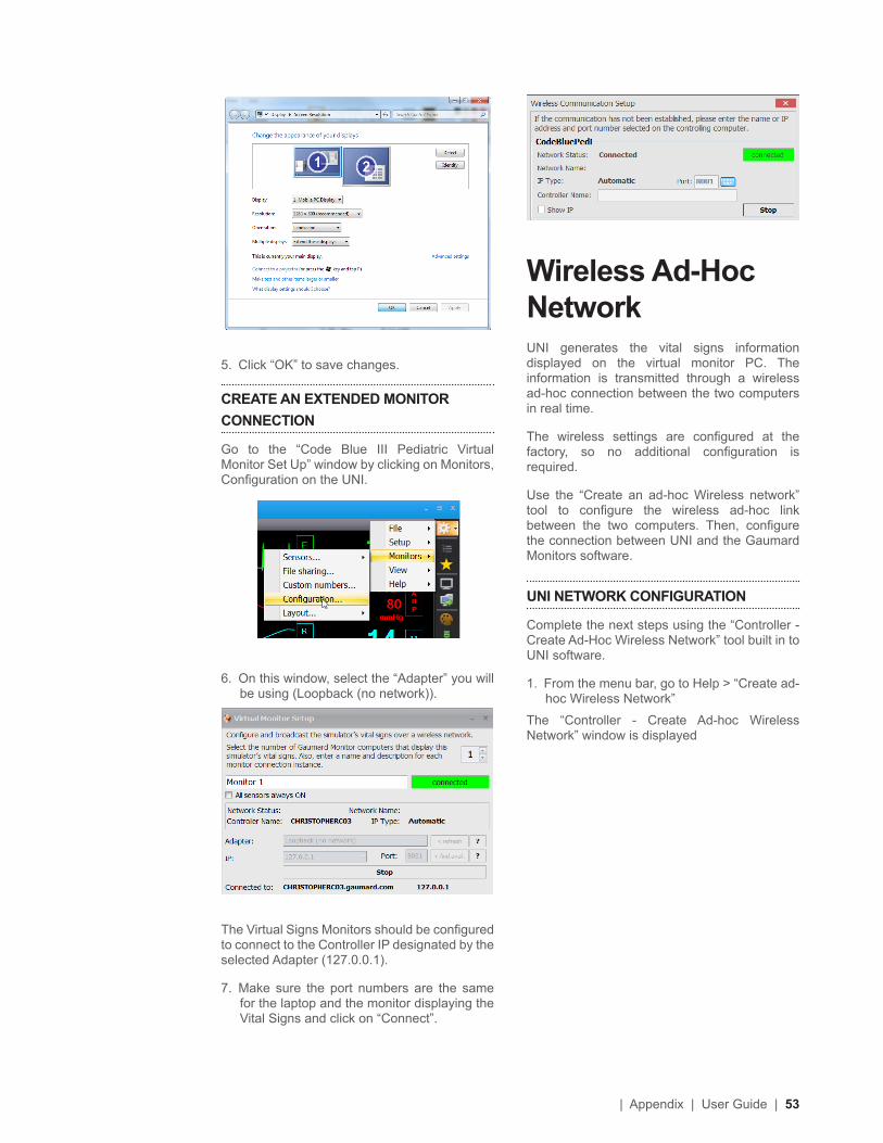
CREATE AN EXTENDED MONITOR CONNECTION
Go to the “Code Blue III Pediatric Virtual Monitor Set Up” window by clicking on Monitors, Configuration on the UNI.
6. On this window, select the “Adapter” you will be using (Loopback (no network)).
The Virtual Signs Monitors should be configured to connect to the Controller IP designated by the selected Adapter (127.0.0.1).
7. Make sure the port numbers are the same for the laptop and the monitor displaying the Vital Signs and click on “Connect”.
Wireless Ad-Hoc NetworkUNI generates the vital signs information displayed on the virtual monitor PC. The information is transmitted through a wireless ad-hoc connection between the two computers in real time.
The wireless settings are configured at the factory, so no additional configuration is required.
Use the “Create an ad-hoc Wireless network” tool to configure the wireless ad-hoc link between the two computers. Then, configure the connection between UNI and the Gaumard Monitors software.
UNI NETWORK CONFIGURATION
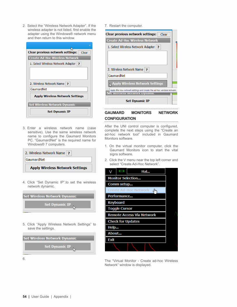
Complete the next steps using the “Controller - Create Ad-Hoc Wireless Network” tool built in to UNI software.
1. From the menu bar, go to Help > “Create ad-hoc Wireless Network”
The “Controller - Create Ad-hoc Wireless Network” window is displayed
54 | User Guide | Appendix |
2. Select the “Wireless Network Adapter”. If the wireless adapter is not listed, first enable the adapter using the Windows® network menu and then return to this window.
3. Enter a wireless network name (case sensitive). Use the same wireless network name to configure the Gaumard Monitors PC. “GaumardNet” is the required name for Windows® 7 computers.
4. Click “Set Dynamic IP”.to set the wireless network dynamic.
5. Click “Apply Wireless Network Settings” to save the settings.
6.
7. Restart the computer.
GAUMARD MONITORS NETWORK CONFIGURATION
After the UNI control computer is configured, complete the next steps using the “Create an ad-hoc network tool” included in Gaumard Monitors software.
1. On the virtual monitor computer, click the Gaumard Monitors icon to start the vital signs software.
2. Click the V menu near the top left corner and select “Create Ad-Hoc Network”.
The “Virtual Monitor - Create ad-hoc Wireless Network” window is displayed.
| Appendix | User Guide | 55
BROADCAST
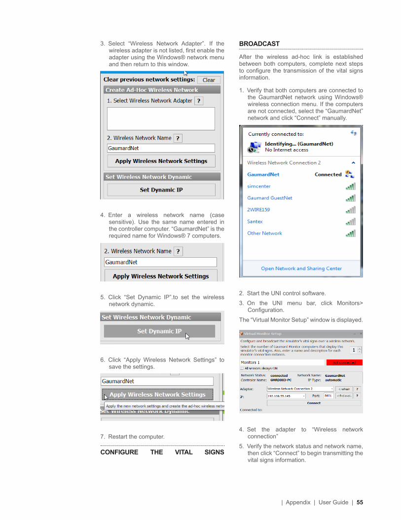
After the wireless ad-hoc link is established between both computers, complete next steps to configure the transmission of the vital signs information.
1. Verify that both computers are connected to the GaumardNet network using Windows® wireless connection menu. If the computers are not connected, select the “GaumardNet” network and click “Connect” manually.
2. Start the UNI control software.
3. On the UNI menu bar, click Monitors> Configuration.
The “Virtual Monitor Setup” window is displayed.
4. Set the adapter to “Wireless network connection”
5. Verify the network status and network name, then click “Connect” to begin transmitting the vital signs information.
3. Select “Wireless Network Adapter”. If the wireless adapter is not listed, first enable the adapter using the Windows® network menu and then return to this window.
4. Enter a wireless network name (case sensitive). Use the same name entered in the controller computer. “GaumardNet” is the required name for Windows® 7 computers.
5. Click “Set Dynamic IP”.to set the wireless network dynamic.
6. Click “Apply Wireless Network Settings” to save the settings.
7. Restart the computer.
CONFIGURE THE VITAL SIGNS
56 | User Guide | Appendix |
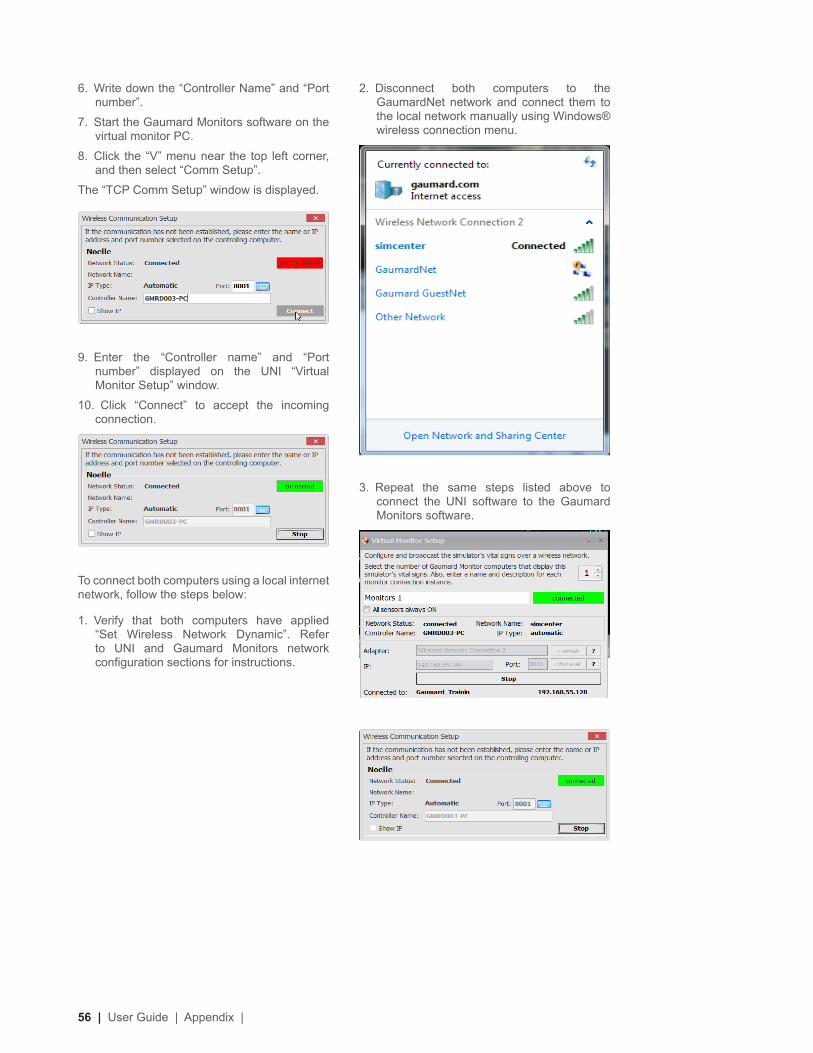
2. Disconnect both computers to the GaumardNet network and connect them to the local network manually using Windows® wireless connection menu.
3. Repeat the same steps listed above to connect the UNI software to the Gaumard Monitors software.
6. Write down the “Controller Name” and “Port number”.
7. Start the Gaumard Monitors software on the virtual monitor PC.
8. Click the “V” menu near the top left corner, and then select “Comm Setup”.
The “TCP Comm Setup” window is displayed.
9. Enter the “Controller name” and “Port number” displayed on the UNI “Virtual Monitor Setup” window.
10. Click “Connect” to accept the incoming connection.
To connect both computers using a local internet network, follow the steps below:
1. Verify that both computers have applied “Set Wireless Network Dynamic”. Refer to UNI and Gaumard Monitors network configuration sections for instructions.
| Appendix | User Guide | 57
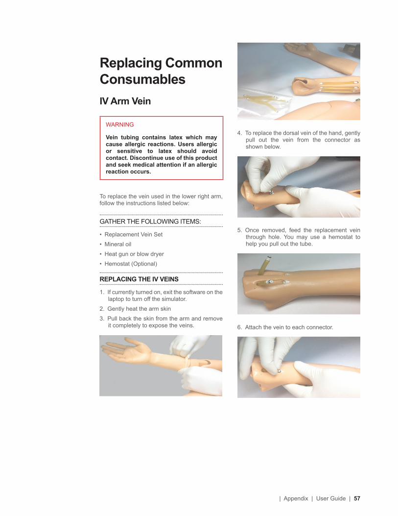
4. To replace the dorsal vein of the hand, gently pull out the vein from the connector as shown below.
5. Once removed, feed the replacement vein through hole. You may use a hemostat to help you pull out the tube.
6. Attach the vein to each connector.
Replacing Common ConsumablesIV Arm Vein
WARNING
Vein tubing contains latex which may cause allergic reactions. Users allergic or sensitive to latex should avoid contact. Discontinue use of this product and seek medical attention if an allergic reaction occurs.
To replace the vein used in the lower right arm, follow the instructions listed below:
GATHER THE FOLLOWING ITEMS:
• Replacement Vein Set
• Mineral oil
• Heat gun or blow dryer
• Hemostat (Optional)
REPLACING THE IV VEINS
1. If currently turned on, exit the software on the laptop to turn off the simulator.
2. Gently heat the arm skin
3. Pull back the skin from the arm and remove it completely to expose the veins.
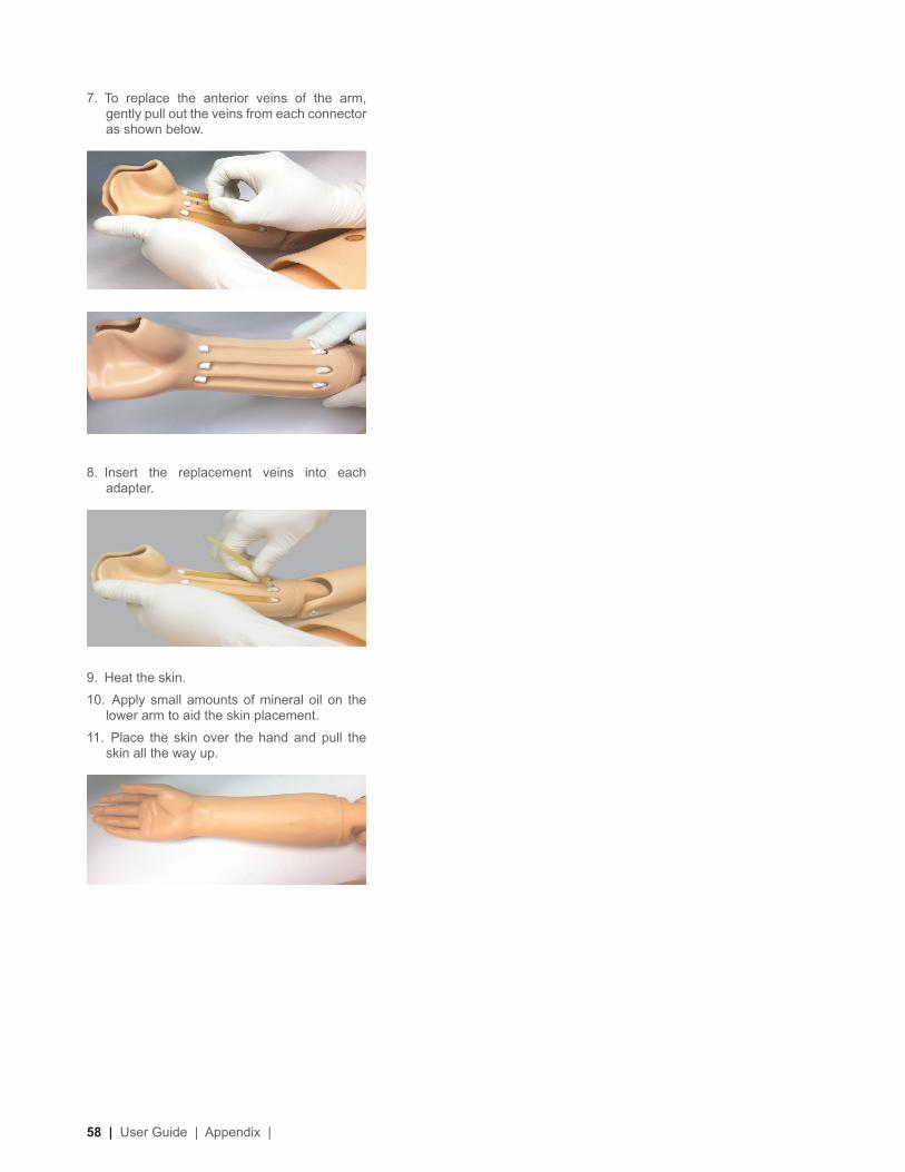
58 | User Guide | Appendix |
7. To replace the anterior veins of the arm, gently pull out the veins from each connector as shown below.
8. Insert the replacement veins into each adapter.
9. Heat the skin.
10. Apply small amounts of mineral oil on the lower arm to aid the skin placement.
11. Place the skin over the hand and pull the skin all the way up.

| Appendix | User Guide | 59
WarrantyEXCLUSIVE ONE-YEAR LIMITED WARRANTY
Gaumard warrants that if the accompanying Gaumard product proves to be defective in material or workmanship within one year from the date on which the product is shipped from Gaumard to the customer, Gaumard will, at Gaumard’s option, repair or replace the Gaumard product.
This limited warranty covers all defects in material and workmanship in the Gaumard product, except:
Damage resulting from accident, misuse, abuse, neglect, or unintended use of the Gaumard product;
Damage resulting from failure to properly maintain the Gaumard product in accordance with Gaumard product instructions, including failure to property clean the Gaumard product; and
Damage resulting from a repair or attempted repair of the Gaumard product by anyone other than Gaumard or a Gaumard representative.
This one-year limited warranty is the sole and exclusive warranty provided by Gaumard for the accompanying Gaumard product, and Gaumard hereby explicitly disclaims the implied warranties of merchantability, satisfactory quality, and fitness for a particular purpose. Except for the limited obligations specifically set forth in this one-year limited warranty, Gaumard will not be liable for any direct, indirect, special, incidental, or consequential damages, whether based on contract, tort, or any other legal theory regardless of whether Gaumard has been advised of the possibilities of such damages. Some jurisdictions do not allow disclaimers of implied warranties or the exclusion or limitation of consequential damages, so the above disclaimers and exclusions may not apply and the first purchaser may have other legal rights.
This limited warranty applies only to the first purchaser of the product and is not transferable. Any subsequent purchasers or users of the product acquire the product “as is” and this limited warranty does not apply.
This limited warranty applies only to the products manufactured and produced by Gaumard. This limited warranty does not apply to any products provided along with the Gaumard product that are manufactured by third parties. For example, third-party products such as computers (desktop, laptop, tablet, or handheld) and monitors (standard or touch-screen) are not covered by this limited warranty. Gaumard does not provide any warranty, express or implied, with respect to any third-party products. Defects in third-party products are covered exclusively by the warranty, if any, provided by the third-party.
Any waiver or amendment of this warranty must be in writing and signed by an officer of Gaumard.
In the event of a perceived defect in material or workmanship of the Gaumard product, the first purchaser must:
Contact Gaumard and request authorization to return the Gaumard product. Do NOT return the Gaumard product to Gaumard without prior authorization.
Upon receiving authorization from Gaumard, send the Gaumard product along with copies of (1) the original bill of sale or receipt and (2) this limited warranty document to Gaumard at 14700 SW 136 Street, Miami, FL, 33196-5691 USA.
If the necessary repairs to the Gaumard product are covered by this limited warranty, then the first purchaser will pay only the incidental expenses associated with the repair, including any shipping, handling, and related costs for sending the product to Gaumard and for sending the product back to the first purchaser. However, if the repairs are not covered by this limited warranty, then the first purchaser will be liable for all repair costs in addition to costs of shipping and handling.
Extended Warranty In addition to the standard one year of coverage, the following support plans are available: Two-Year Extension (covers second and third years)
Call for pricing (USA only)

Contact UsE-mail Technical Support: [email protected]
Before contacting Tech Support you must:
1. Have the simulator’s Serial Number
2. Be next to the simulator if troubleshooting is needed.
E-mail Sales and Customer Service: [email protected]
Phone: Toll-free in the USA: (800) 882-6655
Worldwide: 01 (305) 971-3790
Fax: (305) 667-6085
Post: Gaumard Scientific
14700 SW 136 Street
Miami, FL 33196-5691
USA
Office hours: Monday-Friday, 8:30am - 4:30pm EST (GMT-5, -4 Summer Time)
General Information
Gaumard®, ZOE®, Michelle®, Mike®, PEDI®, Susie Simon®, Susie®, Simon® Code Blue®, SIMA Models®, SIMA GYN/AID®, Virtual Instruments®, Codemaker®, Code Blue®, NOELLE®, Simulation Made Easy™, HAL®, CPRLink™, Zack™, RITA™, Chloe™, Seatbelt Susie™, Krash Kids™, Premie™, UNI™, Omni®, SmartSkin™ are Trademarks of
© Gaumard Scientific Company, 2014All rights reserved.Gaumard®, NOELLE®, HAL® are trademarks of Gaumard Scientific Company, Inc.Patented; Other Patents PendingAlways dispose of this product and its components in compliance with local laws and regulations.
®GaumardSimulators for Health Care Education


![Pediatric Code Blue 3 [Read-Only] - Virginia … 1 Pediatric Code Blue FOCUS on Medications Objectives The learner will be able to: 1. List commonly used pediatric code drugs based](https://img.pdfslide.us/doc/110x75/5ccdd14888c993fb7c8bc86e/pediatric-code-blue-3-read-only-virginia-1-pediatric-code-blue-focus-on-medications.jpg)