Embed Size (px)
Citation preview
5600 East Commerce
Coconino County Drainage Design
Criteria Manual
5600 East Commerce
Flagstaff, Arizona 86004
(928) 679-8300 Office
(928) 679-8301 Fax
Website: www.coconino.az.gov/PublicWorks
Revised August 2020
DRAINAGE DESIGN CRITERIA MANUAL
i August 2020
Table of Contents
1.0 GENERAL CONDITIONS AND REQUIREMENTS ............................................ 1
1.1 PURPOSE AND INTENT .................................................................................... 1
1.2 LEGAL AUTHORITY .......................................................................................... 1
1.3 APPLICABILITY ............................................................................................... 1
1.4 REFERENCES ................................................................................................... 2
1.5 DEVIATION FROM ADOPTED STANDARDS ........................................................ 2
2.0 DRAINAGE REPORTS ................................................................................ 3
2.1 GENERAL INFORMATION ................................................................................. 3
2.2 APPLICABILITY REQUIREMENTS ..................................................................... 3
2.2.1 Subdivision Applications ................................................................... 4
2.2.2 Rezoning Applications ....................................................................... 4
2.3 FLOODPLAIN STUDIES AND MAP REVISIONS ................................................... 4
2.3.1 General Guidelines ............................................................................ 5
2.4 DRAINAGE REPORT REQUIREMENTS ................................................................ 6
2.4.1 Drainage Statement .......................................................................... 6
2.4.2 Phase I Drainage Report ................................................................... 6
2.4.2.1 REPORT CONTENTS ..................................................................... 7
2.4.2.2 DRAWING CONTENTS .................................................................. 8
2.4.3 Phase II Drainage Report .................................................................. 9
2.4.3.1 REPORT CONTENTS ................................................................... 10
2.4.3.2 DRAWING CONTENTS ................................................................ 15
2.5 SUBMITTAL REQUIREMENTS .......................................................................... 16
3.0 HYDROLOGY .......................................................................................... 18
3.1 GENERAL INFORMATION ............................................................................... 18
3.2 QUICK REFERENCE GUIDE ............................................................................. 18
3.3 MODIFICATIONS AND DEVIATIONS ............................................................... 19
3.3.1 Review and Approval ....................................................................... 19
3.3.2 Requirements for Drainage Reports................................................. 19
3.3.3 Minimum Time of Concentration (Tc)............................................... 19
3.3.4 Selection of Runoff Coefficient (C)................................................... 19
3.3.5 Rainfall Losses ................................................................................ 20
4.0 HYDRAULICS.......................................................................................... 23
4.1 GENERAL INFORMATION ............................................................................... 23
DRAINAGE DESIGN CRITERIA MANUAL
ii August 2020
4.2 QUICK REFERENCE GUIDE ............................................................................. 23
4.3 MODIFICATIONS AND DEVIATIONS ............................................................... 24
4.3.1 Review and Approval ....................................................................... 24
4.3.2 Requirements for Drainage Reports................................................. 24
4.3.3 Street Drainage ............................................................................... 24
4.3.3.1 COUNTY STREET DRAINAGE POLICIES ......................................... 24
4.3.3.2 DESIGN FREQUENCY AND ALLOWABLE SPREAD ............................. 24
4.3.3.3 CATCH BASIN SELECTION .......................................................... 25
4.3.3.4 INLET CLOGGING ...................................................................... 25
4.3.3.5 ROADSIDE DITCHES .................................................................. 26
4.3.4 Storm Drains ................................................................................... 26
4.3.4.1 COUNTY STORM DRAIN POLICIES ................................................ 26
4.3.4.2 MANHOLES AND JUNCTION STRUCTURES ..................................... 27
4.3.4.3 STORM DRAIN DESIGN .............................................................. 29
4.3.4.4 STORM DRAIN CONDUIT MATERIAL SELECTION ............................ 31
4.3.5 Culvert and Bridge Requirements .................................................... 33
4.3.5.1 SIZING .................................................................................... 33
4.3.5.2 VELOCITY ................................................................................ 35
4.3.5.3 MATERIALS .............................................................................. 35
4.3.5.4 MINIMUM COVER ...................................................................... 35
4.3.5.5 LOW WATER CROSSINGS ........................................................... 36
4.3.5.6 INLETS AND OUTLETS................................................................ 36
4.3.6 Open Channels ................................................................................ 37
4.3.6.1 COUNTY OPEN CHANNEL POLICY ................................................. 37
4.3.6.2 COMPOSITE CHANNELS ............................................................. 38
4.3.6.3 NATURAL CHANNELS ................................................................. 39
4.3.6.4 VELOCITY ................................................................................ 39
4.3.6.5 GRADE CONTROL ...................................................................... 40
4.3.6.6 CHANNEL LININGS .................................................................... 40
4.3.6.7 MAINTENANCE .......................................................................... 40
4.3.7 Stormwater Storage ........................................................................ 40
4.3.7.1 COUNTY STORMWATER STORAGE POLICY..................................... 40
4.3.7.2 DETENTION FACILITY DESIGN .................................................... 43
5.0 FIRST FLUSH .......................................................................................... 49
DRAINAGE DESIGN CRITERIA MANUAL
iii August 2020
5.1 GENERAL INFORMATION ............................................................................... 49
5.2 DEFINITIONS ................................................................................................ 49
5.3 FIRST FLUSH POLICY .................................................................................... 49
5.4 REFERENCES ................................................................................................. 50
List of Tables
TABLE 3-1 HYDROLOGY REFERENCES ...................................................................... 18 TABLE 3-2 SURFACE RETENTION LOSS AND EFFECTIVE IMPERVIOUS AREA ESTIMATES FOR VARIOUS LAND USES .......................................................................................... 20 TABLE 4-1 HYDRAULIC REFERENCES ....................................................................... 23 TABLE 4-2 INLET CLOGGING FACTORS .................................................................... 25 TABLE 4-3 MANHOLE SPACING CRITERIA ................................................................. 28 TABLE 4-4 CULVERT DESIGN .................................................................................. 34 TABLE 4-5 CULVERT CLOGGING FACTORS ................................................................ 35
DRAINAGE DESIGN CRITERIA MANUAL
1 August 2020
1.0 GENERAL CONDITIONS AND REQUIREMENTS
1.1 PURPOSE AND INTENT
This Manual has been developed to assist in the design and evaluation of public and private stormwater management facilities within the boundaries of Coconino County, Arizona. Stormwater management policies, design procedures and design criteria are presented herein for conducting hydrologic and hydraulic studies, designs and
evaluations. Although the intent of this chapter is to establish uniform design practices, it neither replaces the need for engineering judgment nor precludes the use of information not presented. Other accepted engineering procedures may be used to conduct hydrologic and hydraulic studies if prior approval from the County Engineer is obtained.
The overall goals for the development of this manual are to:
• Ensure compliance with applicable floodplain and stormwater management regulations, policies and design criteria.
• Minimize public expenditures for drainage projects.
• Minimize the review time of drainage report and/or grading and drainage plan submittals.
• Provide consistent policies and criteria that will result in uniform practices and
drainage infrastructure within Coconino County.
• Improve the water quality of stormwater runoff within Coconino County.
Compliance with the requirements in this Manual does not relieve the owner, developer, engineer or contractor from obtaining and following the permit requirements of other applicable agencies.
1.2 LEGAL AUTHORITY
Coconino County, a political subdivision of the State of Arizona, shall not knowingly issue any permit(s) - for construction or improvements on any property - which will allow an adversely impacting alteration of the volume, velocity or location of waters entering or exiting adjoining properties.
The property owners or their authorized representatives applying for County issued permits must obtain a written approval from the County Engineer or his/her designee
before issuance of permits. If the permit approval requires engineering analysis, then the engineer’s report and construction plans must conform to the principles and practices in this Coconino County Drainage Design Criteria Manual and Engineering Design and Construction Manual.
1.3 APPLICABILITY
The policies, design criteria and procedures presented in this Manual are applicable to the design and analysis of drainage facilities of both public improvement and
DRAINAGE DESIGN CRITERIA MANUAL
2 August 2020
private development projects within Coconino County. However, the applicability of many of the items contained herein may have limited ranges.
The hydrologic and hydraulic design criteria presented in this Manual are based on
generally accepted engineering procedures and criteria, but the direct applicability of these criteria to an individual project must be verified by an Arizona Registered Professional Civil Engineer.
1.4 REFERENCES
The latest version of the Arizona Department of Transportation (ADOT) Highway Drainage Design Manual, Volume 2 – Hydrology has been adopted for hydrologic
computations. The latest version of the Flood Control District of Maricopa County (FCDMC) Drainage Design Manual – Hydraulics has been adopted for hydraulic computations. Where certain exclusions, modification or supplements to the sections of the adopted manuals are required, they are stated within the specific chapter of this Manual. If a subsequent update to the ADOT or FCDMC is in conflict with this Manual, the Engineer shall seek clarification from the County Engineer.
1.5 DEVIATION FROM ADOPTED STANDARDS
The County Engineer or his/her designee may approve a Waiver that would allow deviations from these standards under the criteria outlined in the Waiver Request Form. All known deviations must be approved before approval of the Engineering Plans for construction. The latest version of Waiver Request Form can be found on the Coconino County website.

DRAINAGE DESIGN CRITERIA MANUAL
3 August 2020
2.0 DRAINAGE REPORTS
2.1 GENERAL INFORMATION
Drainage reports and/or engineered grading and drainage plans are required to:
• Analyze the impact that the proposed development or project will have on stormwater discharges;
• Provide adequate data to ensure that the development is designed to be
protected from flooding and conforms to applicable floodplain and stormwater management regulations;
• Provide data for the design of public and private drainage facilities.
Drainage reports shall be of sufficient detail to demonstrate that the development or project will not create drainage or flooding problems and that any on-site drainage facilities are properly sized to detain and/or convey the design storm flows.
The purpose of this Chapter is to present criteria for submittals of drainage reports, floodplain studies, grading and drainage plans, and public drainage improvement plans to Coconino County for review and approval.
2.2 APPLICABILITY REQUIREMENTS
Drainage reports will be required for the following land development activities:
• Residential, commercial, and industrial subdivisions
• Any multi-family residential or commercial development, parking lot or park
• Application for rezoning in conjunction with a qualifying development project
• Public improvements involving new streets, culverts, storm drains, open channels, and private/public detention facilities or other drainage infrastructure
• Application for Conditional Letter of Map Revision (CLOMR) or Letter of Map Revision (LOMR) to the Federal Emergency Management Agency (FEMA)
• Any other improvements which, in the opinion of the County Engineer, require a report
A drainage report may also be required for application for a building permit, floodplain use permit, or grading permit if site conditions warrant or if, in the opinion from the County Engineer or his/her designee, drainage issues affect the development of the site.
Drainage reports submitted to the County for review and approval shall be prepared and sealed by an Arizona Registered Professional Civil Engineer who demonstrates proficiency in the specific area of design. Drainage reports shall conform to the Phase I or Phase II criteria set forth in this Manual.
DRAINAGE DESIGN CRITERIA MANUAL
4 August 2020
Coconino County recommends discussing all proposed drainage submittals with County Engineering staff before preparation or submittal.
2.2.1 Subdivision Applications
Subdivision drainage studies shall analyze all drainage basins within a tributary area at the point that they enter the subdivision or confluence within the subdivision.
The size limitation for the various types of delineations may be adjusted up or down depending on the conditions of the specific subdivision with the approval of the County Engineer. If channelization of an existing drainageway is proposed, both a pre-development and post-development analysis will be necessary to illustrate the
effects of the proposed improvements.
2.2.2 Rezoning Applications
Drainage reports and plans for rezoning applications submitted in conjunction with a development project need to address the manner in which stormwater is to be managed in conjunction with development of the project. Most rezoning applications will require submittal of a Phase I Drainage Report (See Section 2.4.2). Detailed
hydrologic and hydraulic analyses will not be required for most rezoning applications, unless the County Engineer determines that the site drainage is a limiting factor in the successful development of the subject site.
2.3 FLOODPLAIN STUDIES AND MAP REVISIONS
Detailed floodplain studies (i.e., Technical Data Support Notebooks) are required for the following applications to FEMA:
• Conditional Letter of Map Revision (CLOMR)
• Letter of Map Revision (LOMR)
• Physical Map Revision (PMR)
Floodplain studies may also be required by the County Engineer for the following:
• Conditional Letter of Map Amendment (CLOMA)
• Conditional Letter of Map Revision Based on Fill (CLOMR-F)
All FEMA applications must be reviewed by the County Engineer before submitting to FEMA. The Coconino County Floodplain Overlay should be consulted for locations where the above FEMA applications may be required. Flood studies may also be required by the County Engineer for other development(s) that may adversely affect floodplain depths.
It may also be necessary to determine areas where floodplain delineations and
drainage analysis may be appropriate, and to justify the method used to calculate and identify the hazard areas:
DRAINAGE DESIGN CRITERIA MANUAL
5 August 2020
• Detailed Floodplain Study: Drainage basin areas greater than 160 acres will include an HEC-RAS or other backwater analysis.
• Approximate Floodplain Study: Drainage basin areas between 40 and 160 acres
will include at a minimum a normal depth analysis of flooding extents.
• Drainage Path Analysis: Drainage basin areas between 10 and 40 acres will identify and quantify flows for all drainage paths.
Floodplain studies submitted to the County for review and approval shall be prepared and sealed by an Arizona Registered Professional Civil Engineer with demonstrated proficiency in hydrologic and hydraulic modeling.
Coconino County will review all floodplain studies for technical compliance and completeness. Review and approval by the Arizona Department of Water Resources (ADWR) may be required for all floodway revisions and new hydrologic studies. All local and federal review fees associated with map revision requests are the responsibility of the applicant.
Specific guidelines for flood risk mapping can be found in Code of Federal
Regulations and the FEMA Policy Standards for Flood Risk Analysis and Mapping (FEMA Policy 204-078-1) February 2019 or latest revision and/or addendum.
Floodplain study report formats shall be in accordance with ADWR State Standard 1 – State Standard for Technical Support Data Notebook, August 2012 or latest revision.
Hydrologic modeling performed in FEMA studies shall be in accordance with the
Chapter 3 of this Manual and shall utilize a FEMA accepted hydrologic model.
Likewise, hydraulic studies shall be in accordance with Chapter 4 of this Manual and shall utilize a FEMA accepted hydraulic model.
2.3.1 General Guidelines
Hydraulic models required for map revision requests to FEMA are typically as follows:
1. Duplicate Effective Model (natural and floodway models, when available)
• Using the same computer program (e.g., HEC-2, HEC-RAS), run the model on your computer and check the result with the output to make sure the model was duplicated
• Assures the baseline is correct and the revised model will tie back into the effective model upstream of the revised reach
2. Corrected Effective Model
• Using a newer version of the same program
DRAINAGE DESIGN CRITERIA MANUAL
6 August 2020
• More detailed cross sections that reflect conditions that existed when the original model was developed
• Fix technical errors
• An improved computer model or improved bridge routine
• Add bridges, culverts, or other structures that existed but were not modeled
• Becomes the new base model to measure impacts of development/construction
3. Existing Conditions Model
• Update the corrected effective model to include existing conditions natural changes in the floodplain
• Reflects fill in the floodway fringe since original model was developed, and other channel improvements
• Other bridges and culverts
• Used as baseline model to measure the effects solely attributed to the
“project" as reflected by the post-project model
4. Post-Project Model
• Reflects the project (built or proposed) and determines the impacts of the project
2.4 DRAINAGE REPORT REQUIREMENTS
Where floodway analysis is required, the approach shall conform to current FEMA
requirements.
2.4.1 Drainage Statement
For projects NOT affected by significant offsite flows or as approved by the County Engineer, a Drainage Statement demonstrating that no offsite flows affect the site may be put on the plans and submitted in a memorandum.
Rational Method calculations may be utilized for sites with all affective drainage
basins totaling an area of less than 160 acres.
2.4.2 Phase I Drainage Report
The Phase I Report will review, at a conceptual level, the feasibility and design characteristics of the proposed development or project. The Phase I Drainage Report shall be on 8.5" x 11” paper (except drainage maps) and be properly bound. An electronic version of the report and models shall also be submitted. The report
DRAINAGE DESIGN CRITERIA MANUAL
7 August 2020
shall be in accordance with the following outline and contain at a minimum the applicable information listed.
2.4.2.1 REPORT CONTENTS
General Location and Description
A. Location
• Owner/Developer Name
• Assessor’s Parcel Number(s)
• City, County, State Highway and local streets within ¼ mile of the subdivision or the area to be served by the drainage improvements
• Major drainageways and facilities
• Names of surrounding developments
• General project description
B. Description of Property
• Area in acres
• Ground cover (type of ground cover and vegetation)
• Major drainageways, floodplains
• Existing irrigation facilities, such as ditches and canals
• Existing and proposed land use
• Description and location of existing or proposed wastewater treatment and disposal system
Drainage Basins and Sub-Basins
A. Major Basin Description
• Reference to all drainageway planning studies such as flood hazard delineation reports, drainageway planning reports, and flood insurance rate map (FIRMs)
• Basin drainage characteristics, existing and planned land uses within the basin.
• Identification of all nearby irrigation facilities within ½ mile of the property boundary, which will influence or be influenced by the local drainage.
• Soils Classification Map
• Identification of all detention facilities
DRAINAGE DESIGN CRITERIA MANUAL
8 August 2020
B. Sub-Basin descriptions shall include all of the above and the following:
• Discussion of historic drainage patterns of the property in question
• Discussion of off-site drainage patterns and impact on development under
existing and fully developed basin conditions,
• Discussion of proposed methods for managing stormwater quality during the construction phase
Drainage Facility Design
A. General Concept
• Discussion of existing drainage patterns
• Discussion of off-site runoff considerations
• Discussion of anticipated and proposed drainage patterns and improvements
• Discussion of the content of tables, charts, figures, maps or drawings presented in the report
B. Discussion of hydrologic, hydraulic, and other analysis methodologies used
in the report
C. Specific Details
• Discussion of drainage problems encountered and solutions at specific design points
• Discussion of detention storage and outlet design
• Discussion of first flush strategies
References
• Reference all criteria, master plans, and technical information used in support of drainage concept.
2.4.2.2 DRAWING CONTENTS
All report figures shall be a maximum of 36" X 48" in size.
General Location Map
A map shall be provided in sufficient detail to identify drainage patterns entering and leaving the development and general drainage patterns. The map should be at a suitable scale to show the path of all drainage from the upper end of any off-site basins to the defined major drainageways. The map shall identify any major facilities on or affecting the property (i.e., development, irrigation ditches, existing detention facilities, culverts, storm sewers, etc.) along the flow path to the nearest
DRAINAGE DESIGN CRITERIA MANUAL
9 August 2020
drainageway. Basins and divides are to be identified and topographic contours are to be included.
Floodplain Information
The location of the parcel shall be plotted on the appropriate FEMA FIRM or Floodway Map, if available, and a copy provided in the report.
Drainage Plan:
Map(s) of the proposed development at a scale of 1" = 20' to 1" = 200' on a 24" X 36" drawing shall be included. The plan shall show the following:
1. Existing topographic contours at 5-foot maximum intervals. In terrain where
the slope exceeds 15%, the maximum interval is 20 feet. The contours shall extend a minimum of 100 feet beyond the property lines. Depending on the proposed use and site conditions, USGS Topographic Quadrangle maps may be acceptable upon approval of the County Engineer.
2. All existing drainage facilities, both onsite and offsite, that significantly impact the site.
3. Approximate flooding limits.
4. Conceptual major drainage facilities, including detention basins, storm drains, sewage facilities, swales, riprap, and outlet structures in the detail consistent with the proposed development plan.
5. Major drainage boundaries and sub-boundaries, both off-site and on-site. When defining basin and sub-basin boundaries, define them along basin
divides that actually drain to the concentration point, not along property lines or other arbitrary lines.
6. Any off-site features influencing development.
7. Proposed flow directions and, if available, proposed contours.
8. Legend to define map symbols.
9. Title block in lower right corner.
10. Tabular reference of basin, area, peak runoff rates for each storm frequency.
2.4.3 Phase II Drainage Report
The purpose of the Phase II Drainage Report is to identify and define detailed solutions to the problems which may occur on-site and off-site, as a result of the development. In addition, those drainage problems that exist on-site before development must be addressed. The Phase II Drainage Report shall be submitted
during the subdivision process with the application for a Preliminary Plan. All reports shall be on 8.5” x 11” paper (except drainage maps) and properly bound. An
DRAINAGE DESIGN CRITERIA MANUAL
10 August 2020
electronic version of the report and models shall also be submitted. The drawings, computer disks, figures, plates and tables shall be bound with the report. The report shall include a cover letter presenting the preliminary design for review and shall
be prepared by or supervised by an Arizona Registered Professional Civil Engineer. The report shall contain a signed seal and certification sheet as follows:
"This report and drainage plan for the Phase II drainage design of (Name of Development) was prepared by me (or under my direct supervision) in accordance with the provisions of the "Drainage Planning submittal Requirements" of Coconino County and other regulations of the Coconino
County Flood Control District. I understand that Coconino County does not, and will not, assume liability for the calculations, design elements, or drainage facilities designed by others."
The following statement is required on all grading and drainage plans:
"Adequate drainage, erosion and sediment control measures, best management practices, and/or other stormwater management facilities shall
be provided and maintained at all times during construction. Damages to adjacent property and/or the construction site caused by the contractor’s or property owner's failure to provide and maintain adequate drainage and erosion/sediment control for the construction area shall be the responsibility of the contractor and/or property owner."
2.4.3.1 REPORT CONTENTS
The Phase II Drainage Report shall be in accordance with the following outline and contain the applicable information listed:
General Location and Description
A. Location
• Owner/ Developer Name
• Assessor’s Parcel Number(s)
• Township, range, section
• Local streets within and adjacent to the subdivision with ROW width shown
• Major drainageways, facilities and easements
• Names of surrounding development, land uses, and identification of present zoning
B. Description of Property
• Area in acres
• Ground cover (type of trees, shrubs, vegetation, general soil conditions, topography, and slope)
• All drainageways and floodplains
DRAINAGE DESIGN CRITERIA MANUAL
11 August 2020
• Project description
• Irrigation facilities
• Proposed land use
Drainage Basins and Sub-Basins
A. Major Basin Description
• References to all drainageway planning studies, such as flood hazard delineation reports, drainageway planning reports, and flood insurance rate maps
• Major basin drainage characteristics, existing and planned land uses
• Identification of all irrigation facilities within the basin, which will influence or be influenced by the local drainage
• Soils Classification Map
• Identification of all detention facilities
B. Sub-Basin Description
• Discussion of historic drainage patterns of the property in question
• Discussion of off-site drainage flow patterns and the impact on development under existing and fully developed basin conditions, as defined by the Community Development Department
Drainage Design Criteria
A. Regulations
• Discussion of the optional provisions selected
B. Development Criteria and Constraints
• Discussion of previous drainage studies (i.e., project master plans or Phase 1 Drainage Reports) for the site in question that influence or are influenced by the drainage design and how the plan will affect drainage design for the site
• Discussion of existing drainage studies prepared for adjacent projects
• Discussion of the drainage impact of site constraints, such as streets, utilities, existing structures and developments
C. Hydrologic Criteria and Results
• Identify design rainfall depths and/or intensities
• Identify runoff calculation method
• Identify detention discharge/volumes and storage calculation method
DRAINAGE DESIGN CRITERIA MANUAL
12 August 2020
• Identify design storm recurrence intervals
• Discussion and justification of other criteria or calculation methods used that are not presented in or referenced by this Manual
• Summary table of pre and post-development watershed areas and peak discharges for the 2, 10, 25, and 100-year return periods for the controlling storm duration
D. Hydraulic Criteria
• Identify references/methodologies used in performing hydraulic analysis
• Discussion of other drainage facility design criteria used that are not
presented within this Manual
E. Variances from this Manual
• Discussion of any deviations from the Manual including the approved County waiver
Drainage Facility Design
A. General Concept
• Discussion of existing drainage patterns
• Discussion of off-site runoff considerations and compliance with applicable criteria
• Discussion of the content of tables, charts, figures, plates or drawings presented in the report
• Discussion of proposed drainage patterns and/or improvements
• Discussion of the stormwater runoff quality aspects of the drainage design including those activities necessary to control erosions and sedimentation during construction
B. Drainage Design (as applicable)
Storm Drain Systems:
• Storm drain plans including profile(s)
• The design frequency, discharge, and pipe capacity
• Pipe size, length, type, and slope(s), inlet/outlet invert elevations
• Outlet treatment
• Invert elevations in and out and rim elevations for all manholes and junction structures
• Existing and proposed grades and pipe cover
• Proposed utility crossings and vertical separations
DRAINAGE DESIGN CRITERIA MANUAL
13 August 2020
• Typical trench detail(s)
Open Channels:
• The design frequency, design discharge, and channel capacity
• Velocities at the design discharge for all different grades
• Channel grade(s)
• Typical cross-sections(s)
• Transition details
• Hydraulic Grade Line (HGL) and available freeboard
• Channel lining(s)
• Drainage easement or right-of-way widths and setbacks
• Hydraulic calculations
• Scour and erosion protection measures
Culverts:
• Design frequency and design discharge
• Culvert slope and design velocities
• Inlet and outlet invert elevations
• Hydraulic calculations for inlet and outlet control conditions
• Design and allowable headwater and tailwater elevations
• Headwalls
• Inlet and outlet erosion and scour protection measures
• Plotted headwater elevation(s) with contours in plan view
• Culvert profile w/ controlling headwater elevation, pipe size and type, and slope
• Typical trench detail
• Temporary erosion and sediment control measures for channel construction or culvert/bridge crossings shall also be included on public improvement plans
C. Specific Details
• Discussion of drainage problems encountered and solutions at specific design points
• Discussion of detention storage and outlet design
• Discussion of maintenance access and aspects of the design
• Discussion of easements and tracts for drainage purposes
DRAINAGE DESIGN CRITERIA MANUAL
14 August 2020
• First flush calculations
D. Conclusions
• Compliance with Standards
• Discussion of compliance with Coconino County Drainage Design Criteria
E. Drainage Plan
• Discussion of influence of proposed development on existing drainage conditions
• Discussion of effectiveness of the drainage design to control damage from storm runoff
References
• Reference all criteria and technical information used.
Appendices
A. Hydrologic Computations
• Land-use assumptions regarding adjacent properties
• Initial and major storm runoff at specific design points
• Historic and fully developed (pre/post) runoff computations at specific design points
• Hydrographs at critical design points
• Time of concentration and runoff coefficients
• Unit hydrograph parameters
• Soil characteristics and maps
• Rainfall/runoff calculations and summaries
• Indirect verification
• Other as warranted
B. Hydraulic Computations
• Culvert capacities
• Storm drain capacities
• Hydraulic grade line calculations
• Gutter capacities
• Storm inlet capacity, including inlet control rating at connection to storm
DRAINAGE DESIGN CRITERIA MANUAL
15 August 2020
drain
• Open channel design
• Roadside ditch capacities
• Check dam and/or channel drop design
• Detention area/volume capacity and outlet design, details, and all supporting calculations. Depths of detention basins
• Downstream/outfall system capacity to the major drainageway system
• Scour and erosion protection design
• Other as warranted
2.4.3.2 DRAWING CONTENTS
All report figures shall be a maximum of 36" X 48" in size.
General Location Map
A map shall be provided in sufficient detail to identify drainage flows entering and leaving the development and general drainage patterns. The map should be at a
suitable scale and show the path of all drainage from the upper end of any off-site basin to the defined major drainageways. The map shall identify any major construction (e.g., development, irrigation ditches, existing detention facilities, storm drains along the entire path of drainage. Basins and divides are to be identified and topographic contours are to be included. USGS Quadrangle maps (7.5 - minute) are acceptable.
Floodplain Information
The location of the parcel shall be plotted on the appropriate FEMA FIRM and Floodway Map, if available, and a copy provided in the report.
Drainage Plan
Map(s) of the proposed development at a scale of 1” = 20' to 1” = 200' on a 24" X 36" drawing(s) shall be included. The plan(s) shall show the following:
1. Existing (dashed lines) and proposed (solid line) contours at 2-foot maximum intervals. In terrain where the slope exceeds 15%, the maximum interval is 10-feet. The contours shall extend a minimum of 100-feet beyond the property lines. All survey shall be in NAVD88 vertical datum.
2. Property lines, tracts and easements (note the type of easement)
3. Streets, indicating right-of-way width, extents of pavement, curb and
gutter
4. Existing and proposed drainage facilities and structures, including irrigation ditches, roadside ditches, drainageways, gutter flow directions and culverts. All pertinent information, such as material, size, shape, slope and
DRAINAGE DESIGN CRITERIA MANUAL
16 August 2020
location shall also be included
5. Overall drainage area boundary and drainage sub-area boundaries, both off-site and on-site when defining basin and sub-basin boundaries, define
them along basin divides that actually drain to the concentration point, not along property lines or other arbitrary lines.
6. First Flush treatment details if applicable.
7. Proposed type of street flow (i.e., vertical curb or combination curb and gutter), roadside ditch, gutter slope and flow direction, and valley gutters
8. Proposed storm drains and open drainageways, including inlets, outlets,
manholes, culverts, other appurtenances, and channel protection
9. Proposed outfall point for runoff from the developed area and drainage facilities to convey flows to the final outfall point without damage to downstream properties
10. Routing and accumulation of peak discharges at various critical points for the storm runoff event listed on the drawing
11. Routing and accumulation of flows at various critical points for the runoff from various storm frequencies listed in a table on the drawing
12. Volumes, release rates and locations for detention storage facilities and information on outlet works. This shall include design drawings, consisting of plan views, cross-sections and details of the basin, as well as the outlet/inlet works.
13. Identify all flood hazard areas (pre and post development, if applicable), detailed delineations (drainage basins greater than 160 acres), approximate delineations (drainage basins between 40 and 160 acres), and drainage paths (drainage basins between 10 and 40 acres.).
14. Location and elevation of all floodplains affecting the property (detailed delineations)
15. Location and elevations of all existing and proposed utilities affected by or affecting the drainage design
16. Identification of drainage patterns through the development
17. Definition of flow path leaving the development through the downstream properties ending at a major drainageway
18. Legend to define map symbols
19. Title block in lower right-hand comer
20. Location of stormwater pollution prevention activities and identify methods of controlling erosion and sedimentation during grading and construction phase(s).
2.5 SUBMITTAL REQUIREMENTS
All drainage report and plan submittals presented to Coconino County for review
shall be prepared and sealed by an Arizona Registered Professional Civil Engineer
DRAINAGE DESIGN CRITERIA MANUAL
17 August 2020
who demonstrates proficiency in the specific area of design.
The engineer shall be held solely responsible for the correctness and adequacy of all data, drawings, calculations, and reports submitted to the County for review and
approval. In addition, the engineer shall comply with all local, state, and federal floodplain regulations in the design of a development.
The Engineering Division will review drainage report and plan submittals for completeness and general compliance with all applicable local, state, and federal requirements. Approval by the County does not necessarily imply that the design is appropriate, nor that the development is in strict compliance with all applicable
regulations and standards. Review and approval of drainage submittals shall not create liability on the part of the County or its employees for any flood damages that may result from reliance upon any administrative decision made by the County or its employees.
When design procedures, equations, and data not included in this Manual are used, the engineer must provide the County enough information on the methods and data
to enable County staff to evaluate their applicability
DRAINAGE DESIGN CRITERIA MANUAL
18 August 2020
3.0 HYDROLOGY
3.1 GENERAL INFORMATION
Coconino County has adopted the Arizona Department of Transportation Highway Drainage Design Manual, Volume 2 – Hydrology (ADOT Hydrology Manual) for the use of all hydrologic analyses in Coconino County. Coconino County has also established a first flush policy which is outlined in Chapter 5 of this Manual. The
County Engineer has the discretion for modifications and/or the approval of additional analyses as deemed appropriate.
The ADOT Hydrology Manual is adopted in whole with the exceptions defined in the following sections. At the time of the publishing of this Manual the current ADOT Hydrology Manual was the Second Edition, dated 2014.
3.2 QUICK REFERENCE GUIDE
The following is a quick reference guide for hydrologic analysis in Coconino County.
TABLE 3-1 HYDROLOGY REFERENCES
Topic Notes
Rainfall depths and intensities
NOAA Atlas 14
NOAA Atlas 14 data can be accessed through NOAA’s Hydrometeorological Design Studies Center
The frequency storm shall be used for the
temporal rainfall distribution unless justified by the engineer
Rational Method Acceptable for drainage areas less than or equal to 160 acres
Time of Concentration Tc ≥10 minutes (See Section 3.3.3 for
exceptions)
Rainfall-Runoff Modeling
Unit Hydrograph method, for drainage areas greater than 160 acres.
HEC-HMS is the preferred methodology for rainfall-runoff modeling and the 24-hour storm duration shall be modeled
Rainfall Losses Green and Ampt
Unit Hydrographs Clark Unit Hydrograph
DRAINAGE DESIGN CRITERIA MANUAL
19 August 2020
Channel Routing Muskingum-Cunge, Kinematic Wave, and Modified Puls Routing are acceptable methods
Storage Routing Level Pool Storage Routing
Transmission Losses Transmission Losses are not permitted in Coconino County without prior approval from the County Engineer
Regional Regression The USGS Scientific Investigations Report 2014-5211: Methods for Estimating Magnitude and Frequency of Floods in Arizona, Developed with Unregulated and Rural Peak-Flow Data through Water year 2010 shall be utilized for regression
analyses.
The USGS StreamStats tool may be used for verification and comparative purposes only
3.3 MODIFICATIONS AND DEVIATIONS
3.3.1 Review and Approval
Review and approval will be required by Coconino County in all instances where the ADOT Hydrology Manual requires review and approval.
3.3.2 Requirements for Drainage Reports
The requirements and methodologies for the documentation of hydrologic and hydraulic analyses in Coconino County are described in Chapter 2 – Drainage
Reports.
3.3.3 Minimum Time of Concentration (Tc)
A minimum Time of Concentration (Tc) of 10-minutes shall be used in the estimation of rainfall intensity; however, there may be instances where a shorter Tc may be more appropriate and may be required by the County Engineer. At no time will a Tc less than 5-minutes be allowed.
3.3.4 Selection of Runoff Coefficient (C)
There may be instances in Coconino County where a custom runoff coefficient (C) that differs from the curves presented in the ADOT Hydrology Manual may be more appropriate.
In all cases where a custom runoff coefficient (C) is used, justification for this value must be presented and documented as well as a comparison made to the available
DRAINAGE DESIGN CRITERIA MANUAL
20 August 2020
runoff coefficients (C) in the ADOT Hydrology Manual. All custom runoff coefficients (C) must be approved by the County Engineer.
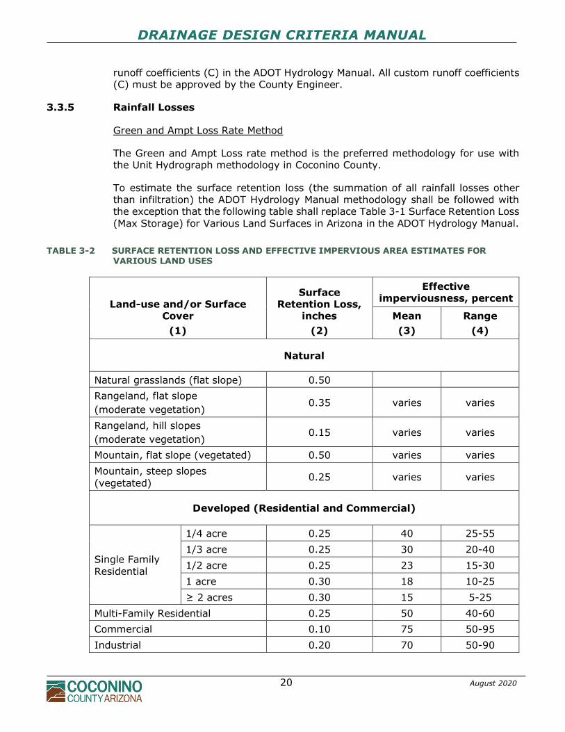
3.3.5 Rainfall Losses
Green and Ampt Loss Rate Method
The Green and Ampt Loss rate method is the preferred methodology for use with the Unit Hydrograph methodology in Coconino County.
To estimate the surface retention loss (the summation of all rainfall losses other than infiltration) the ADOT Hydrology Manual methodology shall be followed with the exception that the following table shall replace Table 3-1 Surface Retention Loss
(Max Storage) for Various Land Surfaces in Arizona in the ADOT Hydrology Manual.
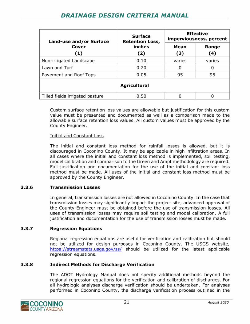
TABLE 3-2 SURFACE RETENTION LOSS AND EFFECTIVE IMPERVIOUS AREA ESTIMATES FOR VARIOUS LAND USES
Land-use and/or Surface Cover
(1)
Surface Retention Loss,
inches
(2)
Effective imperviousness, percent
Mean
(3)
Range
(4)
Natural
Natural grasslands (flat slope) 0.50
Rangeland, flat slope
(moderate vegetation) 0.35 varies varies
Rangeland, hill slopes
(moderate vegetation) 0.15 varies varies
Mountain, flat slope (vegetated) 0.50 varies varies
Mountain, steep slopes
(vegetated) 0.25 varies varies
Developed (Residential and Commercial)
Single Family
Residential
1/4 acre 0.25 40 25-55
1/3 acre 0.25 30 20-40
1/2 acre 0.25 23 15-30
1 acre 0.30 18 10-25
≥ 2 acres 0.30 15 5-25
Multi-Family Residential 0.25 50 40-60
Commercial 0.10 75 50-95
Industrial 0.20 70 50-90
DRAINAGE DESIGN CRITERIA MANUAL
21 August 2020
Land-use and/or Surface Cover
(1)
Surface Retention Loss,
inches
(2)
Effective imperviousness, percent
Mean
(3)
Range
(4)
Non-irrigated Landscape 0.10 varies varies
Lawn and Turf 0.20 0 0
Pavement and Roof Tops 0.05 95 95
Agricultural
Tilled fields irrigated pasture 0.50 0 0
Custom surface retention loss values are allowable but justification for this custom value must be presented and documented as well as a comparison made to the allowable surface retention loss values. All custom values must be approved by the County Engineer.
Initial and Constant Loss
The initial and constant loss method for rainfall losses is allowed, but it is discouraged in Coconino County. It may be applicable in high infiltration areas. In all cases where the initial and constant loss method is implemented, soil testing, model calibration and comparison to the Green and Ampt methodology are required. Full justification and documentation for the use of the initial and constant loss method must be made. All uses of the initial and constant loss method must be
approved by the County Engineer.
3.3.6 Transmission Losses
In general, transmission losses are not allowed in Coconino County. In the case that transmission losses may significantly impact the project site, advanced approval of the County Engineer must be obtained before the use of transmission losses. All uses of transmission losses may require soil testing and model calibration. A full
justification and documentation for the use of transmission losses must be made.
3.3.7 Regression Equations
Regional regression equations are useful for verification and calibration but should not be utilized for design purposes in Coconino County. The USGS website, https://streamstats.usgs.gov/ss/ should be utilized for the latest applicable regression equations.
3.3.8 Indirect Methods for Discharge Verification
The ADOT Hydrology Manual does not specify additional methods beyond the regional regression equations for the verification and calibration of discharges. For all hydrologic analyses discharge verification should be undertaken. For analyses performed in Coconino County, the discharge verification process outlined in the
DRAINAGE DESIGN CRITERIA MANUAL
22 August 2020
Yavapai County Drainage Design Manual – Hydrology, Section 7.11 Indirect Methods for Discharge Verification should be followed with the exception of utilizing the Regional Regression equations as discussed in Section 3.3.7 of this Manual.
This process utilizes three indirect procedures for verification, and in general, all three procedures should be followed. They include the following:
• A graph of numerous peak discharges versus drainage area curves
• A graph of estimated 100-year discharges and maximum recorded discharges versus drainage area for gaged watersheds in Arizona
• Regression equations and data graphs for flood regions in Coconino County
These indirect procedures should be followed and documented as part of the drainage report.
3.3.9 Watersheds above 7000 Feet
When watersheds are located above 7000 feet, the engineer shall consider rain on snow or rain on frozen ground in calculating stormwater runoff. The engineer shall document and justify the procedures utilized in the Drainage Report. An example of
possible justification would be analyzing local gages and identifying when seasonal peak discharges occur for a specific area.
DRAINAGE DESIGN CRITERIA MANUAL
23 August 2020
4.0 HYDRAULICS
4.1 GENERAL INFORMATION
Coconino County has adopted the Flood Control District’s Drainage Design Manual for Maricopa County-Hydraulics (FCDMC Hydraulics Manual) for the use of all hydraulic analyses in Coconino County. The County Engineer has the discretion for modifications and/or the approval of additional analyses as deemed appropriate.
The FCDMC Hydraulics Manual is adopted in whole with the exceptions defined in the following sections. At the time of the publishing of this Manual the current FCDMC Hydraulics Manual was the Fourth Edition dated December 14, 2018.
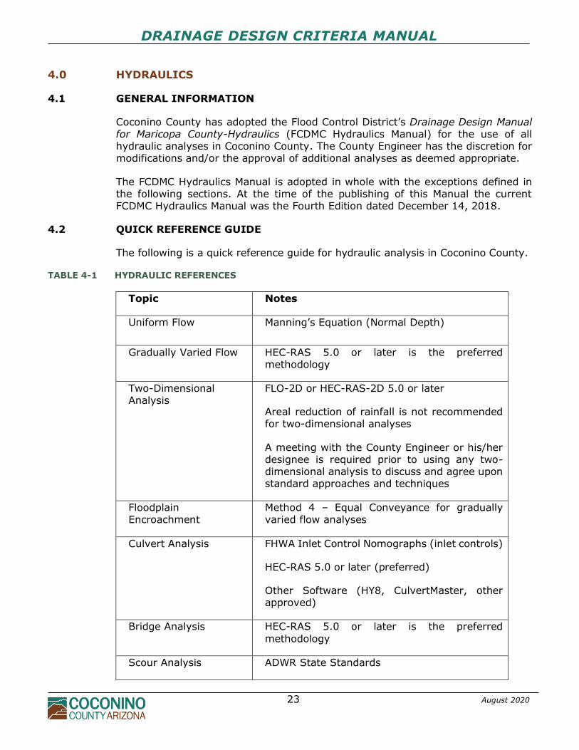
4.2 QUICK REFERENCE GUIDE
The following is a quick reference guide for hydraulic analysis in Coconino County.
TABLE 4-1 HYDRAULIC REFERENCES
Topic Notes
Uniform Flow Manning’s Equation (Normal Depth)
Gradually Varied Flow HEC-RAS 5.0 or later is the preferred methodology
Two-Dimensional Analysis
FLO-2D or HEC-RAS-2D 5.0 or later
Areal reduction of rainfall is not recommended for two-dimensional analyses
A meeting with the County Engineer or his/her designee is required prior to using any two-dimensional analysis to discuss and agree upon standard approaches and techniques
Floodplain Encroachment
Method 4 – Equal Conveyance for gradually varied flow analyses
Culvert Analysis FHWA Inlet Control Nomographs (inlet controls)
HEC-RAS 5.0 or later (preferred)
Other Software (HY8, CulvertMaster, other approved)
Bridge Analysis HEC-RAS 5.0 or later is the preferred
methodology
Scour Analysis ADWR State Standards
DRAINAGE DESIGN CRITERIA MANUAL
24 August 2020
4.3 MODIFICATIONS AND DEVIATIONS
4.3.1 Review and Approval
Review and approval will be required by Coconino County in all instances where the
FCDMC Hydraulics Manual requires review and approval.
4.3.2 Requirements for Drainage Reports
The requirements and methodologies for the documentation of hydrologic and hydraulic analyses in Coconino County are described in Chapter 2 – Drainage Reports.
4.3.3 Street Drainage
4.3.3.1 COUNTY STREET DRAINAGE POLICIES
1. Street drainage and roadways shall be designed to maintain the natural drainage patterns existing before development, whenever possible.
2. The street section shall be designed to convey local runoff only and shall not be
used as major stormwater carriers for contributing watersheds.
3. Drainage facilities shall be installed to convey runoff under streets or street
grades shall be set so diversion of runoff or ponding will not occur on adjacent properties.
4. Typical section street cross slopes shall not be decreased or increased, and curb
heights shall not be increased to create more carrying capacity for runoff. Curb overtopping is not permitted for the 10-year design storm.
5. Public streets with inverted crowns are prohibited.
6. Existing alleys shall not be used to convey runoff unless the entire alley is
designed and constructed to convey runoff to the nearest downstream street.
7. Drainage facilities shall be placed to intercept runoff from sources outside the street section to avoid concentrated flows onto and over sidewalks or curb and gutter.
8. In all cases, street drainage shall be confined to the public right-of-way. Runoff which leaves the right-of-way shall do so in a controlled manner and shall be conveyed in an appropriate tract or drainage easement.
4.3.3.2 DESIGN FREQUENCY AND ALLOWABLE SPREAD
For local curbed street sections, runoff from the 10-year design storm must be contained between the curbs of the street and the 100-year flow within the right-
of-way.
DRAINAGE DESIGN CRITERIA MANUAL
25 August 2020
For collector and arterial curbed street sections, at least one twelve (12) foot travel lane in each direction must remain free from flooding for the 10-year design storm and the 100-year flow must be contained within the right-of-way. If either of the
above two criteria are exceeded, storm drain facilities will be required. In all instances, the 10-year design storm must be contained within the combined street gutter and storm drain system.
4.3.3.3 CATCH BASIN SELECTION
Catch basin inlets for use within right-of-way, an easement, or public property shall be per MAG Standard Details. Slotted drain inlets are only permitted for special
circumstances, as approved by the County Engineer, where standard drainage inlets will not suffice. Slotted drain inlets on a longitudinal grade function best when designed and constructed in conjunction with a curb opening inlet and when debris is not a factor. Slotted inlets for public storm drains are not permitted in sump locations due to high clogging potential and sediment deposition problems in the pipe section.
Transverse Slotted drains function best for shallow low velocity sheet flow (e.g., in parking lots) but are not recommended for more concentrated flow due to the small opening width and low splash over velocity threshold. Slotted drain inlets, when used, shall be set in concrete for vehicular loading and to
maintain constant grade. They should be accessible at both ends of the pipe for maintenance/cleaning. This may be accomplished by extending the pipe ends beyond the area requiring the opening length.
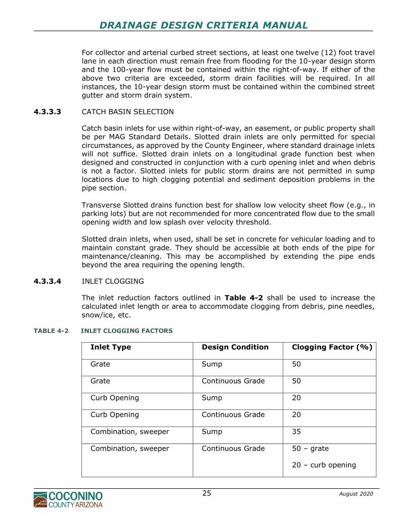
4.3.3.4 INLET CLOGGING
The inlet reduction factors outlined in Table 4-2 shall be used to increase the calculated inlet length or area to accommodate clogging from debris, pine needles,
snow/ice, etc.
TABLE 4-2 INLET CLOGGING FACTORS
Inlet Type Design Condition Clogging Factor (%)
Grate Sump 50
Grate Continuous Grade 50
Curb Opening Sump 20
Curb Opening Continuous Grade 20
Combination, sweeper Sump 35
Combination, sweeper Continuous Grade 50 – grate
20 – curb opening
DRAINAGE DESIGN CRITERIA MANUAL
26 August 2020
Combination, equal length Sump 50
Combination, equal length Continuous Grade 50
Slotted Drain Continuous Grade 20
4.3.3.5 ROADSIDE DITCHES
Roadside ditches or channels for rural, uncurbed street sections shall be designed for the 25-year design storm. The runoff shall be contained within the roadside
channels with the allowable water depth elevation below the roadway subgrade to avoid unnecessary saturation of the subgrade and/or aggregate base course shoulder. The minimum depth of a roadside channel shall be 1.5 feet and shall be designed per the typical sections in the County's Engineering Design and Construction Manual.
The underlying soil conditions, depth of flows, flow velocities, and maintenance shall be considered in the roadside channel design. Long reaches of riprap lined roadside channels should be avoided, if possible, due to long-term maintenance problems.
4.3.4 Storm Drains
4.3.4.1 COUNTY STORM DRAIN POLICIES
1. All offsite runoff from whatever source must be considered in the design of a
storm drain system if such runoff could affect the street that the storm drain is serving.
2. Storm drain systems serving collector and arterial streets must keep one 12-foot lane of traffic open in each direction for the 10-year design storm and the 100-year storm within the right-of-way. Storm drain systems for local streets
must keep the 10-year design flow between the curbs.
3. The minimum design frequency for all public storm drain facilities shall be the 10-year design storm. The 100-year design storm must also be analyzed to ensure that the 100-year storm is maintained within the right-of-way.
4. The minimum easement width for public storm drains 36 inches in diameter or less shall be 16 feet. For multiple pipe installations or pipe diameter greater than 36 inches, the easement width shall be the conduit width(s) plus 8 feet on each side of the conduit measured from its edge.
5. The minimum acceptable diameter for any public storm drain pipe is 18 inches.
Mainline storm drains shall be at least 24 inches in diameter.
6. New storm drains and manholes shall not run longitudinally under existing or future curb and gutter or sidewalk, whenever possible.
7. When connecting into an existing storm drain system, the existing storm drain
DRAINAGE DESIGN CRITERIA MANUAL
27 August 2020
systems shall be analyzed to determine available capacity.
8. Hydraulic grade line computing software such as StormCAD, SWMM, and
SewerGEMS may be used.
Maintenance Considerations
It is essential that maintenance be considered during both the design and construction of storm drain systems. Common maintenance problems associated with storm drains include debris, sedimentation, scour, piping, roadway or embankment settlement, and structural damage to the conduit. The likelihood of
scour and abrasion inside the conduit should also be considered during design. Access for inspection and maintenance of storm drains as well as drainage inlets must also be considered.
Clearing accumulated debris and sediment from storm drain and inlets is a routine maintenance requirement for any facility owner, however this problem is often overlooked during construction and adequate sediment/erosion control precautions
should be undertaken.
Piping, roadway or embankment settlement, and structural damage problems, when they occur, are usually attributed to poor construction practices and can be avoided through proper design, installation specifications and inspections.
4.3.4.2 MANHOLES AND JUNCTION STRUCTURES
Location and Spacing Manhole location and spacing criteria has been developed primarily for storm drain maintenance requirements. At a minimum, manholes are required for the following locations:
1. At junctions where two or more storm drains converge (not including laterals from adjacent catch basins)
2. At vertical deflections 3. Changes in pipe size 4. At horizontal alignment changes as outlined below:
PIPE DIAMETER (INCHES) DEFLECTION 18–42 >22 ½ degrees 42 and up > 45 degrees
5. Manholes may also be required by the County Engineer at other locations to
facilitate maintenance.
Manholes at vertical deflections shall be at or as close as practical to the point of deflection, with allowance for manufactured bends. If the manhole is not at the point of deflection, it shall be located immediately upstream of the deflection.
In addition to the above criteria, manholes will be required at intermediate points
DRAINAGE DESIGN CRITERIA MANUAL
28 August 2020
along long runs of storm drain in accordance with the criteria outlined in Table 4-3.
TABLE 4-3 MANHOLE SPACING CRITERIA
Pipe Diameter (in) Maximum Distance (ft)
18-24 300
27-36 400
42 and up 500
If possible, manholes shall not be located in traffic lanes. However, if it is not possible to avoid locating a manhole in a traffic lane, every effort shall be made to
avoid locating it within a street intersection and/or the vehicle wheel path.
Manhole Configurations Storm drain manholes shall be constructed in accordance with current adopted MAG Standard Details. For storm drains 36 inches and larger, a vertical riser or
prefabricated "tee" to the storm drain may be used with prior approval from the County Engineer and special design considerations. A pressure manhole shaft and pressure frame and cover are required whenever the design hydraulic grade line elevation at the manhole is within 12 inches of the adjacent ground elevation.
To differentiate storm drain manholes from sewer or communication conduits, the manhole cover shall have the words "STORM DRAIN" cast into the top surface of the cover in accordance with MAG Standard Detail 424 lettering requirements. Manhole depths shall be determined by the storm drain profile and surface
topography. Common depths range from 5-13 feet. Manholes which are shallower or deeper may require special design considerations. Deep manholes (greater than 12 feet) shall be 60-inches in diameter and must be designed to withstand soil pressures. If a manhole will extend below the water table, it must also be designed to withstand hydrostatic pressure and/or seepage. Manhole shafts shall be 60 inches in diameter for storm drain pipes 36 inches in diameter or greater.
Manhole Shaping A minimum drop of 0.10 foot is required through all storm drain manholes. A drop of 0.3 feet is preferred for a manhole with two contributing laterals, if possible. Where a storm drain changes direction through a manhole without increasing in
size, a drop of 0.4 feet is preferred, if possible.
DRAINAGE DESIGN CRITERIA MANUAL
29 August 2020
4.3.4.3 STORM DRAIN DESIGN
Design Velocity and Slope
The minimum allowable storm drain slope for any storm drain pipe shall be 0.5% or the slope which will produce a velocity of 3 feet per second for the pipe flowing full, whichever is greater. Slopes less than 0.5 % require special approval by the County Engineer. Desirable minimum velocity is 5 feet per second, however all storm drains shall be
designed such that the minimum self-cleaning velocity will be 3 feet per second flowing full. The minimum slopes necessary to ensure a velocity of 3 ft/sec in storm drains can be calculated by the equation below:
𝑠 = (𝑛𝑉)2
2.208𝑅4
3⁄
where: s = the slope of the hydraulic grade line, ft/ft n = Manning's roughness coefficient V = the mean velocity (3 ft/sec) R = the hydraulic radius, ft.
The following relative flow conditions for different depths in a circular pipe should also be noted:
1. Peak flow occurs at 93 percent of the height of the pipe. This means that if a pipe is designed for full flow, the design will be slightly conservative.
2. The velocity in a pipe flowing half-full is the same as the velocity for full flow. 3. Flow velocities for surcharged storm drains with hydraulic grade line
elevations above the top of pipe (pressure flow) are greater than velocities at full flow.
4. As the depth of flow drops below half-full, the flow velocity drops off rapidly.
Alignment
Storm drains shall be straight, with uniform slopes between manholes, whenever possible. Curved storm drains may be permitted when long radius curves are necessary to conform to street layout, however, storm drains smaller than 4 feet in diameter should not be designed with curves. Long radius bends are available from many suppliers and are preferred as a means of changing direction in storm drains
4 foot in diameter or larger, unless a manhole is required. The radius of curvature specified should coincide with standard curves available in the type of material utilized. The minimum radius shall not be less than 100 feet.
Storm Drain Conduit Size
The minimum pipe diameter for public storm drains shall be 18 inches in diameter for laterals and 24 inches in diameter for mainlines. The use of elliptical or arched
DRAINAGE DESIGN CRITERIA MANUAL
30 August 2020
pipe for storm drains is not recommended and must be approved by the County Engineer before use. Storm drain pipe sizes shall increase in the downstream direction. Decreasing the pipe size in the downstream direction is not permitted
even for flow on a steeper slope or for pressure profiles.
Separation Requirements Installation and backfill requirements for public storm drains shall be in accordance with Coconino County Engineering Design & Construction Standards.
Vertical and horizontal separation requirements for storm drain conduit to waterlines shall be the same as for sewer pipes per the Coconino County Engineering Design and Construction Manual. The minimum clearance between storm drains and all other dry underground
utilities shall be the same as sewer pipes per the Coconino County Engineering Design and Construction Manual. Utility crossings shall be at angles greater than 45 degrees, if possible. Crossings of open channels may require extra depth, concrete encasement, channel stabilization or other protective measures where scour is anticipated.
Storm Drain Outfalls All storm drain systems will have an outfall where the flow is discharged into either a natural watercourse, artificial channel, another storm drain system, or other drainage facility. Several aspects of storm drain outlet design must be given
consideration, including but not limited to the invert of the storm drain outlet, tailwater elevation(s), type of receiving watercourse, orientation of the outlet, and local scour. If the outfall is a wash or stream, it may be necessary to consider the coincidental probability of two hydrologic events occurring at the same time. There may be
instances where excessive tailwater causes flow to back up in the storm drain system and possibly cause surcharging out inlets and manholes. The invert of the storm drain outlet shall be a minimum of 1 foot above the channel invert at the same point, whenever possible. The tailwater depth at the storm drain outlet must be considered carefully for
purposes of evaluating the hydraulic grade line. Storm drains that discharge into open channels shall be provided with an appropriate headwall/wingwall. Projecting outlets are not permitted. The orientation of a storm drain outlet into a wash or channel should be positioned so the discharge
is pointed in the downstream direction. This will reduce turbulence and the potential for local scour. If the outlet is perpendicular to the direction of flow in the receiving channel, erosion of the opposite channel bank must be considered. If an erosion potential exists, a channel bank lining of riprap or other appropriate material will be required. An energy dissipater may be required if outlet velocities warrant.
DRAINAGE DESIGN CRITERIA MANUAL
31 August 2020
4.3.4.4 STORM DRAIN CONDUIT MATERIAL SELECTION
Factors such as life expectancy, durability, physical strength, depth of cover, joint tightness, hydraulic performance, ease of handling, installation costs, and
maintenance should all be considered in the selection of storm drain materials to maximize performance and cost effectiveness. Permissible pipe materials for public storm drain systems are:
1. Corrugated Metal Pipe (CMP) - 14 Ga., Annular, Aluminized Steel Type 2 per
MAG Section 760. 2. CMP - 14 Ga., Helical Corrugated, Aluminized Steel Type 2 per MAG Section
760. 3. Reinforced Concrete Pipe (RCP) per MAG Section 735. 4. Spiral Rib Metal Pipe (SRP) per MAG Section 760. 5. High Density Polyethylene Pipe (HDPE) per MAG Section 738.
6. Reinforced Concrete Box (RCB) per FCDMC DDM Subsection 5.3.2. All storm drain conduit shall be of sufficient structural strength to withstand AASHTO HS-20-44 loading at a minimum. Special designs may be required depending on loading requirements and depths of backfill.
Corrugated Metal Pipe (CMP) CMP shall be per MAG Standard Specification 760. All metal pipe shall be a minimum of 14-gauge, Aluminized Steel Type 2 pipe. Thicker gauge pipe may be warranted with increases in fill height per manufacturers recommendations.
Standard CPM joints shall be either rivet lap joint construction (annular corrugations) or continuous lock or welded seam (helical corrugations) and wrapped with non-woven geotextile filter fabric or “O” ring gaskets. Reinforced Concrete Pipe (RCP)
Non-reinforced concrete pipe is not permitted for public storm drain systems. All RCP shall be a minimum of Class III under public roadways and shall be manufactured in accordance with the following standards:
*MAG Section 735 - Reinforced Concrete Pipe. *ASTM C76 - Reinforced Concrete Culvert, Storm Drain and Sewer Pipe.
*ASTM C443 - Reinforced Low-Head Concrete Pressure Pipe. *ASTM C443 - Joints for Circular Concrete Sewer and Culvert Pipe, Using Rubber Gaskets ASTM C665 - Reinforced Concrete D-Load Culvert, Storm Drain and Sewer Pipe.
Material standards for concrete aggregate, steel reinforcing, Portland cement, and gaskets are also referenced in the above specifications. RCP should be designed for each individual project. Indirect design is typically used and is presented in the Concrete Pipe Handbook (SAMM or 3EB) prepared by the American Concrete Pipe Association.
DRAINAGE DESIGN CRITERIA MANUAL
32 August 2020
The maximum allowable velocity for standard RCP shall be 20 ft/sec. Velocities greater than 20 ft/sec. may require increases in the compressive strength of the
concrete, increases in specific hardness of the concrete aggregate, increased the cover over the reinforcing steel, or providing plastic lining. Joints for RCP shall be bell and spigot ends with O-ring rubber gaskets conforming to ASTM C443 to provide a watertight joint.
Spiral Rib Steel Pipe (SRP) The minimum pipe thickness shall be 14 gauge for pipe diameters of 18-60 inches and 12 gauge for pipe diameters of 60-72 inches. SRP with diameters greater than 72 inches will require structural design to determine adequate gauge thickness.
Materials for SRP shall meet the following standards:
*AASHTO M274 - Steel Sheet, Aluminum Coated (Type 2) for Corrugated Steel Pipe. *ASTM A819 - Steel Sheet, Aluminum Coated (Type 2) for Storm Sewer and Drainage Pipe.
Pipe shall be manufactured in accordance with the following standards:
*AASHTO M36 - Corrugated Steel Pipe, Metallic-Coated, for Sewers and Drains. *ASTM A760 - Corrugated Steel Pipe, Metallic-Coated, for Sewers and Drains.
*MAG Section 760 - Coating Corrugated Metal Pipe and Arches. SRP shall be designed in accordance with the following standards:
*AASHTO Standard Specification for Highway Bridges, Section 12 - Soil-Corrugated Metal Structure Interaction Systems.
*ASTM A796 - Structural Design of Corrugated Steel Pipe, Pipe Arches, and Arches for Storm and Sanitary Sewers and Other Buried Structures.
Joints for SRP shall be coupling bands conforming to AASHTO M36 with 0-ring gaskets to produce a watertight joint. Coupling bands shall be a minimum of 10½ inches wide and shall be made from aluminized steel of the same thickness as the
pipe. Hardware for coupling bands shall conform to AASHTO M36 and rubber gaskets shall meet the requirements of AASHTO M198. High Density Polyethylene Pipe (HDPE)
HDPE is only allowed for pipe diameters from 18 to 36 inches. HDPE pipe shall meet the following standards:
*MAG Sections 601, 603, and 738. *ASTM F-894.
DRAINAGE DESIGN CRITERIA MANUAL
33 August 2020
HDPE pipe shall be designed so that deflections are limited to 5 percent. Deflections should be determined using the Modified Iowa Deflection Formula.
Joints for HDPE shall be bell and spigot type joints and elastomeric gaskets to provide a watertight joint. Split couplings shall not be used. Joints shall meet AASHTO M294 standards. Mandrill testing may be required at the discretion of the County Engineer. Reinforced Concrete Box (RCB)
Refer to FCDMC DDM Subsection 5.3.2 for design and construction of RCB.
4.3.5 Culvert and Bridge Requirements
Culverts are typically used to convey stormwater through an embankment or may serve as the primary outlet for detention facilities. Culverts are typically aligned with natural washes, watercourses, or open channels which serve as the primary
outfall for local and regional drainageways. The design of culverts is influenced by purpose, hydraulic efficiency, site topography, effects on adjacent property, and cost.
Bridges are typically not practical or warranted for most roadway crossings in Coconino County. However, when bridges are applicable, they shall be designed to convey the 100-year event runoff under the road with at least 2-feet of freeboard
below the bridge low chord, including the effects of pier clogging.
If constructing a culvert or bridge crossing is impracticable for a planned single family development, a low water crossing may be an alternative option. Refer to Section 4.3.5.5 for low water crossing requirements.
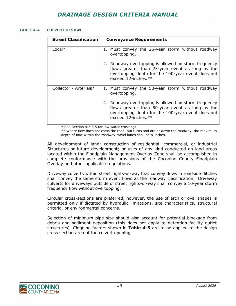
4.3.5.1 SIZING
Minimum diameter for public roadway culverts shall be 18 inches. 12-inch diameter
pipes are permissible for private residential driveway crossings when adequate cover cannot be maintained, if hydraulically adequate. Roadway culverts shall be designed to convey the frequency storm indicated in Table 4-4.
DRAINAGE DESIGN CRITERIA MANUAL
34 August 2020
TABLE 4-4 CULVERT DESIGN
Street Classification Conveyance Requirements
Local* 1. Must convey the 25-year storm without roadway overtopping.
2. Roadway overtopping is allowed on storm frequency flows greater than 25-year event as long as the
overtopping depth for the 100-year event does not exceed 12-inches.**
Collector / Arterials* 1. Must convey the 50-year storm without roadway overtopping.
2. Roadway overtopping is allowed on storm frequency
flows greater than 50-year event as long as the overtopping depth for the 100-year event does not exceed 12-inches.**
* See Section 4.3.5.5 for low water crossings
** Where flow does not cross the road, but turns and drains down the roadway, the maximum
depth of flow within the roadway travel lanes shall be 8-inches.
All development of land; construction of residential, commercial, or industrial Structures or future development; or uses of any kind conducted on land areas
located within the Floodplain Management Overlay Zone shall be accomplished in complete conformance with the provisions of the Coconino County Floodplain Overlay and other applicable regulations.
Driveway culverts within street rights-of-way that convey flows in roadside ditches shall convey the same storm event flows as the roadway classification. Driveway
culverts for driveways outside of street rights-of-way shall convey a 10-year storm frequency flow without overtopping. Circular cross-sections are preferred, however, the use of arch or oval shapes is permitted only if dictated by hydraulic limitations, site characteristics, structural criteria, or environmental concerns.
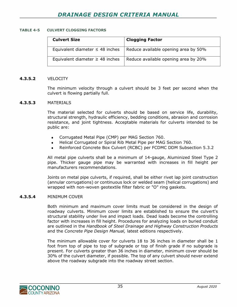
Selection of minimum pipe size should also account for potential blockage from debris and sediment deposition (this does not apply to detention facility outlet structures). Clogging factors shown in Table 4-5 are to be applied to the design cross section area of the culvert opening.
DRAINAGE DESIGN CRITERIA MANUAL
35 August 2020
TABLE 4-5 CULVERT CLOGGING FACTORS
Culvert Size Clogging Factor
Equivalent diameter ≤ 48 inches Reduce available opening area by 50%
Equivalent diameter ≥ 48 inches Reduce available opening area by 20%
4.3.5.2 VELOCITY
The minimum velocity through a culvert should be 3 feet per second when the culvert is flowing partially full.
4.3.5.3 MATERIALS
The material selected for culverts should be based on service life, durability, structural strength, hydraulic efficiency, bedding conditions, abrasion and corrosion
resistance, and joint tightness. Acceptable materials for culverts intended to be public are:
• Corrugated Metal Pipe (CMP) per MAG Section 760.
• Helical Corrugated or Spiral Rib Metal Pipe per MAG Section 760.
• Reinforced Concrete Box Culvert (RCBC) per FCDMC DDM Subsection 5.3.2 All metal pipe culverts shall be a minimum of 14-gauge, Aluminized Steel Type 2 pipe. Thicker gauge pipe may be warranted with increases in fill height per
manufacturers recommendations. Joints on metal pipe culverts, if required, shall be either rivet lap joint construction (annular corrugations) or continuous lock or welded seam (helical corrugations) and wrapped with non-woven geotextile filter fabric or "O" ring gaskets.
4.3.5.4 MINIMUM COVER
Both minimum and maximum cover limits must be considered in the design of roadway culverts. Minimum cover limits are established to ensure the culvert's structural stability under live and impact loads. Dead loads become the controlling factor with increases in fill height. Procedures for analyzing loads on buried conduit are outlined in the Handbook of Steel Drainage and Highway Construction Products and the Concrete Pipe Design Manual, latest editions respectively.
The minimum allowable cover for culverts 18 to 36 inches in diameter shall be 1 foot from top of pipe to top of subgrade or top of finish grade if no subgrade is present. For culverts greater than 36 inches in diameter, minimum cover should be 30% of the culvert diameter, if possible. The top of any culvert should never extend above the roadway subgrade into the roadway street section.
DRAINAGE DESIGN CRITERIA MANUAL
36 August 2020
4.3.5.5 LOW WATER CROSSINGS
Low water crossings or vented fords are allowable for areas of shallow or distributary flow, where the County Engineer and his/her designee agrees that a culvert or
bridge crossing is impracticable, if the following design criteria is met:
1. The maximum water depth crossing the roadway travel lanes for the 100-year peak discharge does not exceed 12-inches, and
2. The velocity does not exceed 8 feet per second (ft/s), and 3. Low water crossing surfaces are to be constructed per MAG Standard Detail
552 (Concrete Surface) or comparable all-weather surface as approved by the County Engineer, and
4. The crossing accesses a single-family home development A waiver process is available to individual parcel applicants seeking single family type developments who believe a culverted, bridge, or low water crossing as
described above is impracticable. The waiver request must describe that meeting this requirement:
1. Is financially impractical, and/or
2. Would significantly change historical flow patterns or would result in
significant adverse impacts to properties. If waived, the applicant must provide a notarized letter, recorded as an addendum to the property deed at the County Recorder’s Office, that acknowledges the design is not in compliance with County standards. A template letter of non-compliance is
available from the County Community Development Department. If the legal access does not allow access to the lots, parcels or fractional interests by emergency vehicles, neither the county nor its agents or employees are liable from damages resulting from the failure of emergency vehicles to reach the lot, parcel, or fractional interest.
If low water roadway crossings of washes with a 100-year peak discharge of 500 cfs or greater are approved for a development, signage, barricades or other flood warning devices may be required at the discretion of the County Engineer, for public safety and welfare.
4.3.5.6 INLETS AND OUTLETS
Culvert inlets shall match the geometry of the roadway embankment whenever possible. To reduce headwater elevations, improve inlet capacity, and prevent damage to roadway embankments and culvert ends, the use of concrete headwalls and wingwalls, side or slope tapered inlets, and beveled edges may be required. Commercial end sections are permitted on culverts 36 inches in diameter or less, if
the design headwater is acceptable and other embankment protection measures are used. Concrete headwalls are required on all public culverts greater than 36 inches in diameter.
DRAINAGE DESIGN CRITERIA MANUAL
37 August 2020
Aprons may be required if high headwater depths are encountered or the approach velocity in the channel will cause scour. Aprons shall extend at least one pipe diameter beyond the pipe invert and shall not protrude above the normal channel
or streambed elevation. Concrete headwalls and aprons shall be constructed in accordance with MAG Standard Details and/or Arizona Department of Transportation, Highways Division, Structures Section Standard Drawings.
Metal pipe culverts with a span or diameter greater than 48 inches shall have a cutoff wall where the outlet velocity and downstream bed material may result in local scour. Inlet riprap protection for commercial end sections shall extend around and over the top of the inlet a minimum of 2 feet. Roadways designed for overtopping will
require additional slope protection for the upstream and downstream spillway sections. Drop inlets should typically be used when the upstream channel sides and bottom are bank protected and significant sediment loads are not anticipated; to avoid sediment deposition and plugging of grated inlets. It should be noted that HDS-5
inlet control nomographs do not apply to drop inlets since the additional losses caused by the plunging flow are not accounted for. In this case, the analysis for a storm drain inlet should be used.
Maintenance Considerations
It is essential that maintenance be considered during both the design and construction of culverts. Common maintenance problems associated with culverts
include debris, sedimentation, scour, piping, roadway or embankment settlement, and structural damage to the conduit. The likelihood of scour and abrasion inside the conduit should also be considered during design. Access for inspection and maintenance of culverts must also be considered.
Clearing accumulated debris and sediment from culverts is a routine maintenance requirement for any facility owner, however this problem is often overlooked during
construction and adequate sediment/erosion control precautions should be undertaken.
Piping, roadway or embankment settlement, and structural damage problems, when they occur, are usually attributed to poor construction practices and can be avoided through proper design, installation specifications and inspections.
4.3.6 Open Channels
4.3.6.1 COUNTY OPEN CHANNEL POLICY
1. All open channel designs and/or related activities shall meet the minimum requirements and/or design criteria for Coconino County, Federal Emergency Management Agency, U.S. Army Corps of Engineers 404 permitting, and the
Arizona Department of Environmental Quality, as applicable.
DRAINAGE DESIGN CRITERIA MANUAL
38 August 2020
2. Safety of the public shall be considered in the selection of location and cross-
sectional geometry of artificial channels.
3. The design of artificial channels shall consider the frequency and type of
maintenance expected and make allowance for access of maintenance equipment. Soil cement linings are not permitted for open channels intended to become public and are discouraged for all channels due to maintenance problems.
4. All artificial open channel drainage systems shall be designed for the 25-year
design storm at a minimum and checked with the 100-year design storm to determine available freeboard, minimum finished floor for structure elevations adjacent to the channel, and the potential for flood damages.
5. Channels shall be designed to follow natural drainage alignments whenever possible. Environmental impacts of modifications to natural channels, including disturbance of wildlife habitat, wetlands, and stream bank stability shall be assessed and meet any applicable regulations.
6. The County Engineer may require the Engineer to analyze the downstream
impacts for channels that alter the time-of-concentration and/or the flow attenuation of existing conditions drainageways.
7. All channels which are to be maintained by Coconino County must be dedicated to the County either in fee title or granted as drainage easement and must be formally accepted for maintenance by the County.
8. Unless proper authorization from Coconino County and the adjacent property
owner(s) is obtained, open channels must enter and exit a site where the channel historically flowed.
9. The lining proposed for public channels must be approved by the County
Engineer.
4.3.6.2 COMPOSITE CHANNELS
One of the most influencing factors in the design of artificial channels is the channel lining. The most prominent channel lining types include earth (natural), grass, rock, concrete, and other biotechnical or synthetic measures. These linings can be used alone or in combination to form a composite channel.
Trapezoidal or compound cross-sections are required for public open channels, unless prior approval of an alternate design is obtained from the County Engineer. Channel side slopes shall be stable throughout the entire length and will be dependent upon the channel bank or lining material. Slope stability analysis may be
required in some instances. Side slopes shall be no steeper than 3H:1V for natural vegetal or earth linings and 2H:1V for ungrouted riprap lining. Side slopes for rigid lined channels may be steeper depending on the structural stability of the lining.
DRAINAGE DESIGN CRITERIA MANUAL
39 August 2020
The depth of public open channels shall be determined by computation of the uniform flow depth for the design discharge plus a minimum of one foot of freeboard (see FCDMC Hydraulics Manual Section 6.5.4 for additional required freeboard). The
maximum depth for artificial public channels in residential areas should not exceed 3 feet, including freeboard, for safety considerations unless approved by the County Engineer. Sediment transport requirements must be considered for conditions of flow below the design frequency, especially for multi-use corridors, if applicable. Low and high
flow sections shall be considered in the design of channels with large cross sections and/or a design discharge greater than 50 cubic feet per second.
4.3.6.3 NATURAL CHANNELS
Natural washes, not designated by the County or FEMA as regulatory floodplains, which cross private property are encouraged be left in their natural state, if possible, upon development. Planning and other design measures must be used to protect
development adjacent to natural washes from the flooding and erosion typically associated with increased development. As additional runoff from development is added to a natural channel, these channels can experience erosion and may require on-site detention, grade control, and/or localized bank protection. If relocation of a natural stream channel is unavoidable, the cross-section shape,
meander pattern, roughness, sediment transport capacity, and slope should conform to the existing conditions insofar as practicable. Some means of energy dissipation may be necessary when existing conditions cannot be duplicated. U.S. Army Corps of Engineers Section 404 and Section 401 of the Clean Water Act permitting processes may apply for impacts on Waters of the U.S. such as stream channelization, relocation, bank stabilization, or roadways crossings. Approval by
the County does not supersede or waive compliance with other applicable Federal and State laws. A completed NPDES Notice of Intent form and Stormwater Pollution Protection Plan must be submitted for all grading permit applications that will cause a total site disturbance greater than one acre. Natural channels should be analyzed using field observation, surveyed cross-
sections, and Normal Depth/Uniform Flow (Manning's Equation) or step-backwater methods (HEC-2 or HEC-RAS are preferred), as applicable.
4.3.6.4 VELOCITY
The slope of a proposed channel is typically dependent upon the natural topography. However, variations can be accomplished by altering the channel alignment through a development, by adjusting the elevation of inflow and outflow points, or utilizing
grade control. The selected channel configuration, alignment, and slope should result in a stable channel. The minimum allowable channel slope for public channels shall be 0.5 percent. The maximum allowable velocity for any open channel shall be 18 feet per second unless adequately stabilized and only if approved by the County Engineer.
Abrupt changes in channel slope shall be avoided except when necessary to create a desired hydraulic jump or grade control. When abrupt changes in slope are
DRAINAGE DESIGN CRITERIA MANUAL
40 August 2020
unavoidable, the slope changes should not cause the channel top width to vary by more than 15 percent.
The design engineer shall consider the velocity and flow regime in the design and selection of materials for the channel.
4.3.6.5 GRADE CONTROL
It is recommended to incorporate the use of grade control to limit channel slopes/velocities and preclude the need for channel linings at grade control structures. The use of alternate channel treatments other than riprap is strongly
encouraged. Methods developed by the International Erosion Control Association for channel protection and streambank stabilization are recommended.
4.3.6.6 CHANNEL LININGS
Artificial Channels Artificial open channels have a wide variety of applications ranging from landscaping
swales to large flood control facilities. The selection of the open channel lining type is influenced by numerous factors such as hydraulics, structural features, environmental concerns, sociologic impact, risks and liability, maintenance, and economics. Examples of various types of open channels are depicted in FCDMC Hydraulics Manual Figure 6.6.
Soil cement linings are not permitted for open channels intended to become public and are discouraged for all channels due to maintenance problems.
4.3.6.7 MAINTENANCE
Minimum width of fee title dedications or drainage easements for public open channels shall be dependent upon the top width of the channel, required setbacks, and the need for maintenance access roads adjacent to the channel.
Maintenance access shall be provided along at least one side of all new open channels intended to become public. The minimum maintenance access width shall be 12 feet. Maintenance access may either be necessary adjacent to the top of the channel bank, down into the channel bottom, or a combination of both. In all cases, the right-of-way or drainage easement must be of enough width to allow
maintenance vehicles or equipment to operate freely.
4.3.7 Stormwater Storage
4.3.7.1 COUNTY STORMWATER STORAGE POLICY
1. Stormwater detention is required for all new subdivisions, commercial and industrial developments, redevelopment of non-conforming sites (i.e., existing developed sites that do not have detention that have been razed and
vacant for greater than six months), and other developments that the County Engineer deems required for protection of downstream properties. Refer to Chapter 5 for first flush requirements.
DRAINAGE DESIGN CRITERIA MANUAL
41 August 2020
2. Detention for single-family residential structure or lot (i.e., not associated with
a new subdivision) is not required unless requested by the County Engineer.
3. Detention requirements may be waived by the County Engineer for the
following:
a. Residential subdivisions with lot areas >1 acre in area, if it can be shown that such a waiver will not result in any adverse downstream effects, nor
create any disturbance to the existing drainage patterns both within and adjacent to the subdivision.
b. Developments less than 1/4 acre or increases in impervious area of < 5,000 square feet. It must be demonstrated to the satisfaction of the County Engineer that there will be no increase in the potential for damages to adjacent properties and adequate off-site or downstream
drainage capacity is available. c. Developments with drainage basins adjacent to drainage ways with large
contributory basins if it can be shown that time-to-peak for each hydrograph is offset adequately so as not to affect the peak flowrate in the larger basin drainageway.
4. Detention facility storage volume shall be adequate to attenuate the post-development peak discharge rates to pre-development discharge rates for the 2, 10, and 100-year design storms as determined per requirements in Chapter 3. Reservoir routing calculations must be used to demonstrate that the storage volume is adequate.
5. Detention facility outlet structure release rates shall be less than the pre-development peak runoff rates for the 2, 10, and 100-year storm events, with emergency overflow provisions. Emergency overflow weirs shall be provided on all detention basins and designed to safely convey the 100-year peak. Overtopping of the entire length of the top-of-embankment is not acceptable as an emergency overflow weir. Design calculations are required to
demonstrate that developed peak runoff rates from the 2, 10, and 100-year design storms are controlled.
6. The total combined post-development peak flow rates from a development
cannot exceed the total predevelopment peak flow rate for the 2, 10, and 100-year storms. Drainage flows of all frequencies shall enter and depart the
property to be developed in substantially the same manner as under the pre developed condition.
7. The same methodology shall be used for both pre-development and post-
development analyses. Contributing drainage areas shall be analyzed
separately for purposes of estimating the runoff which must be accepted and conveyed through the site. Flows from offsite drainage areas must be routed around local detention ponds and not co-mingled with flows emanating from the development unless approved by the County Engineer.
8. The use of retention or infiltration systems may be permitted in Coconino
DRAINAGE DESIGN CRITERIA MANUAL
42 August 2020
County, especially in cases where the site is land locked, due to topography, with no means of positive outflow. If a retention system is proposed, sufficient supporting data must be provided to ensure adequate storage volume and
evaluate the functionality of all proposed infiltration retention systems, including but not limited to a soils report addressing soil classification, soil erodibility, soil permeability, slope stability, ground water elevations, and percolation test results. Maximum storage time for ponded water in retention facilities is 36 hours.
9. The use of pavement parking lot storage as the primary detention facility is not permitted unless other sites or detention alternatives are not available and approved by the County Engineer.
10. Roof-top detention storage is not permitted for meeting Coconino County
detention requirements.
11. Individual on-lot storage systems within single family residential developments
is not permitted for meeting Coconino County detention requirements. 12. The minimum lowest floor elevation of any structure adjacent to a detention
facility shall be 1 foot above the 100-year water surface elevation in the facility
or the emergency overflow water surface level, whichever is higher. 13. Developments which are phased shall prepare a master stormwater detention
plan for the entire development. The master stormwater detention plan must either be implemented with the first phase, if possible, or detention must stand alone for each phase. Interim temporary detention facilities may be required
for phasing. 14. Road culverts shall not be utilized as outlet structures for detention basins. 15. The point or points at which a pre-development watercourse enters and leaves
a site shall remain substantially the same after the property has been altered
for the development. Drainage in general, including sheet flow, should leave the site as it did in the pre-developed condition. Developers must coordinate with downstream properties if the drainage exiting their property is to be changed (e.g., predevelopment flow was sheet flow and the post-development discharge is a detention outlet pipe or point discharge). The County Engineer may require the developer to obtain a drainage easement or
written permission from adjacent property owners. 16. Discharges from detention facilities shall be designed to enter established
downstream drainage systems (e.g., drainage channels, natural watercourses, public streets, or storm drain systems) whenever possible. If flows are to be
concentrated or ponded on the upstream or downstream side of the site, either a recorded drainage easement or written permission as determined by the County Engineer must be obtained from the affected property owner(s) before issuance of grading or building permits. Discharge velocities shall be reduced or dissipated to provide non-erosive flows and reduce damages to downstream properties.
DRAINAGE DESIGN CRITERIA MANUAL
43 August 2020
17. Coconino County shall only accept large-scale regional detention basins for
operation and maintenance. The County shall not accept small-scale, local on-
site detention basins for operation, maintenance, or liability. 18. Maintenance of local on-site detention facilities shall be the responsibility of
the property owner or homeowner’s association. The County shall reserve the right to periodically inspect any detention facilities to verify that regular maintenance activities are being performed. Final Plats; Covenants,
Conditions, and Restrictions (CC&R’s); and/or Development Plans shall include a special note stating that (1) the owner(s) shall be solely responsible for the operation, maintenance, and liability for all detention facilities; and, (2) Coconino County may periodically inspect said detention facilities to verify that regular maintenance activities are being performed adequately.
19. Coconino County Parks and Recreation Division must review and approve proposed stormwater detention facilities designed within designated public areas or parks. Review and approval from the Parks and Recreation Commission may also be required.
20. No part of a private detention basin shall be constructed in a public right-of-
way or public utility easement. 21. Site designs which consolidate detention areas into a limited number of larger
facilities are preferred over designs which utilize many small facilities. Designs which will demand considerable maintenance, will be difficult to maintain and access, or utilize numerous small facilities will not be permitted if other
alternatives are physically possible. 22. All new subdivisions are required to provide detention for the entire
subdivision, including the respective one-half of all abutting streets to the subdivision. Two or more subdivisions may join together to provide a common detention facility.
4.3.7.2 DETENTION FACILITY DESIGN
Detention facilities which incorporate basins below grade or embankments shall be designed and constructed as permanent drainage structures which are protected from long term erosion and are as maintenance free as possible. Detention basins and related facilities should be designed to minimize the following typical problems:
• grass and vegetation maintenance
• sedimentation control
• bank deterioration
• standing water or soggy surfaces
• mosquito control
• blockage of outlet structures
• litter accumulation
• maintenance of fences and perimeter plantings
DRAINAGE DESIGN CRITERIA MANUAL
44 August 2020
No detention or retention facility shall retain standing water longer than 36 hours unless the facility has been designed and constructed as a permanent body of water with appropriate health, safety, and water quality measures for such a body of
water.
Basin inlet and outlet structures may be at or below grade or a combination of both. Drainage crossings or culverts shall be provided whenever runoff entering or exiting a basin crosses pedestrian paths or sidewalks.
Riprap aprons or other energy dissipating measures should be used at all inflow points (side slope and basin floor) to reduce velocities and discourage sedimentation. Low flow channels are required on the bottom of basins which serve as multi-use areas and are recommended on all basins. Low flow channels should be designed
with a minimum longitudinal slope of 0.5 percent. Concrete lined low flow channels can be designed with a minimum longitudinal slope of 0.2 percent. If any portion of a detention basin is a retaining wall, design information for determining factors of safety against sliding and overturning is required. Provisions shall also be incorporated to prevent seepage through and under the retaining wall.
Location and Configuration In general, open detention facilities located adjacent to streets or buildings are discouraged. No portion of a detention basin will be permitted within any public right-of-way or public utility easement.
Curvilinear or irregular shapes are required for open surface basins, whenever possible. The designer should vary the shape and side slopes of the basin and maximize the linear footage of the perimeter. Curvilinear contours at areas immediately adjacent to walls or structures is encouraged. The basin shape or floor should have a minimum length to width dimension of 4:1.
Designs that incorporate basins in series with two or more stages or terraces are encouraged. Slope and Depth Criteria The following minimum slope and depth criteria are required for multi-use basins
and basins that have unrestricted access:
• A maximum of 2H:1V for protected side slopes and 3H:1V for unprotected side slopes where depths of ponding are less than three feet.
• A maximum of 4:1 for side slopes where depths of ponding exceed 3 feet.
• Basins greater than 6 feet in depth will require a benched configuration with bench widths at least 3 times the height of the slope above it with a minimum width of 6 feet.
• Basins containing human activity areas shall incorporate access slopes of
8H:1V or flatter (12H:1V for ADA compliance) into the design for ingress and egress.
DRAINAGE DESIGN CRITERIA MANUAL
45 August 2020
A minimum freeboard of 0.5 foot above the 100-year high water elevation is recommended for all detention facilities. Freeboard may include adjacent parking
lot areas. The basin floor should be graded to drain toward the basin outlet. The minimum recommended slope is 0.2 percent. A meandering low flow channel across the basin bottom is recommended to accommodate frequent flows and prevent standing water.
Landscaping and Surface Treatment All detention basins shall include appropriate surface treatment and erosion control measures including but not limited to landscaping, seeding, grass or sod, rock, gravel, or any combination thereof. Regardless of basin side slopes, seeding of the
basin to promote vegetation shall be considered in the design to prevent rill and gully erosion. Trees, shrubs, and other native vegetation may be used on basin side slopes and periphery. Any landscaping placed on the basin floor shall not have a density such that it interferes with the stormwater storage function of the basin or regular
maintenance activities. For basins located adjacent to streets, landscaping density shall be increased along the street frontage to screen the basin from the street. Use of decomposed granite or small gradation rock shall be limited to basin side slopes of 3H: 1V or flatter and is not recommended for use on basin floors, in flow channels, or at the basin inlets and outlets. Use of bio-mass filter landscaping
treatment on basin floors is encouraged. Over-excavation will be required to account for any volume displacement from landscaping islands, boulders, or rock riprap placement within the basin and shall be noted on the Grading & Drainage and Landscape Plans.
Outlet Structures Due to multi-frequency detention requirements, multi-stage outlet structures may be necessary in the design of many detention facilities. The outlet structure(s) should be designed to ensure complete basin drainage and can take the form of drop inlets, culverts, weirs, orifices, or any combination thereof. The use of weirs is
encouraged. FCDMC Hydraulics Manual Figure 9.4 illustrates typical outlet structure configurations. Outlet structures that require manual operation to properly function are not permitted. Outlet structures for detention basins shall be sized based on hydrologic reservoir-
routing calculations and stage-discharge relationships. Inlet control should not always be assumed on detention facility outlet pipes; therefore, outlet pipes should be evaluated using the FHWA, HDS-5 procedures. Outlet structures shall be constructed such that they are physically opposite and the longest distance from the inlet structure(s), whenever possible. The distance
DRAINAGE DESIGN CRITERIA MANUAL
46 August 2020
between outlet structures and inflow points should be maximized to lengthen flow paths and detention times and provide effective settling of pollutants and sediment.
Metal outlet pipes projecting from a basin side slope or embankment are not permitted. Appropriate headwalls, commercial end sections, mitered sloped concrete protection, etc. are required for all outlet structures that incorporate only a pipe/culvert as the primary outlet structure. The minimum recommended outlet culvert size for detention facilities is 12 inches.
Orifice plates are permitted provided the orifice plate is permanent, tamper-proof, and connects to a 12-inch minimum diameter outlet pipe. Outlet structures incorporating orifice plates shall include a trash rack to minimize clogging. FCDMC Hydraulics Manual Figure 9.5 illustrates a recommended method of orifice plate construction.
Outlet pipes less than 12 inches in diameter may require adequate sediment and debris collection measures to be incorporated into the basin design to minimize clogging. Outlet structures shall not be oversized to account for debris blockage or clogging. Sediment traps should also be incorporated into the design of all multi-use detention facilities. FCDMC Hydraulics Manual Figure 9.12 illustrates a sediment trap concept.
Outlet pipes which present a hazard to children (e.g., outlet pipe connects directly to a large storm drain system) should be equipped with a bar/grate configuration in accordance with the International Building Code (IBC) safety requirements to prevent entrance of children into the outlet opening.
Local scour at culvert outlets as well as long term degradation downstream of the facility must be considered in the overall basin design. Erosion control measures such as energy dissipators, cut-off walls, riprap aprons or basins, and rock lined channels shall be provided to reduce outlet velocities and allow flows to return to pre-developed conditions, to as great an extent as possible, before exiting onto the downstream property.
Detention Embankments It is recommended that detention facilities be constructed with the storage volume located entirely below the natural ground or finished grade adjacent to the facility. Use of detention embankments or berms is discouraged due to the potential for
downstream flood hazard in the event of failure, however, the following criteria must be incorporated into the detention embankment design, at a minimum:
• Vegetated embankments shall be less than 20 feet in height and shall have side slopes no steeper than 3:1 (horizontal:vertical). Embankments protected
with riprap or other approved erosion control measure shall be no steeper than 2:1.
• A geotechnical engineering study and slope stability analysis is required for embankments exceeding 10 feet in height or for embankment slopes exceeding those given above. It is recommended that ADWR, Guidelines for
the Design and Construction of Small, Low hazard Potential Embankment
DRAINAGE DESIGN CRITERIA MANUAL
47 August 2020
Dams, be utilized for design criteria.
• Top width of the embankment shall be a minimum of 1/2 the height of the embankment.
• Design of spillways shall also incorporate adequate erosion control and energy dissipating measures to ensure the stability of the embankment. The use of concrete spillways is preferred.
• Seepage through the embankment and piping, particularly along the outside
of the primary outlet conduit and spillway wall, must also be considered in the design of the embankment. Soil used for detention embankments should have a relatively low permeability after placement and shall be compacted to a minimum of 95%.
• No detention facility can be designed to be a jurisdictional dam based on
ADWR criteria without approval of the County Engineer.
A minimum of 1 foot of freeboard above the spillway elevation is required for public detention facilities that incorporate an embankment. The spillway elevation should be set equal to or above the 100-year water surface elevation.
Emergency Overflow All detention facilities shall incorporate provisions for emergency overflow for instances where the primary outlet structure fails or storm events greater than the design capacity occur. The overflow shall be designed to pass the post development 100-year peak discharge at a minimum. Design criteria shall incorporate the
protection of the basin and the method of discharge. The overflow must be conveyed downstream in the same manner as it would have under predevelopment, historic conditions. Spillways for detention facilities that employ embankments must be designed to protect the embankment side slopes, particularly on the downstream side. It is
recommended that the spillway be located to direct flow around the embankment on or through natural ground versus placing the spillway directly over the primary outlet structure. The safety of downstream persons, properties, and consequences of embankment failure should be considered and evaluated.
Safety
Detention facilities in general should be open, visible, and accessible so that persons can appreciate any hazard and guard themselves, and so that rescue efforts, if necessary, are not impeded. To reduce the potential dangers associated with detention facilities the following
recommendations are made in the design and construction:
• The ground surface side slopes around the facility should be made rough. • Break up ponding water with islands, boulders and mounds; put solid objects
for holding onto in the ponding area such as large plants or rocks. • Avoid sudden constrictions and high velocities at outlets. Broad open
rectangular weirs are preferable to anything involving the mouths of pipes and/or creating a hazardous vortex at the outlet.
DRAINAGE DESIGN CRITERIA MANUAL
48 August 2020
• Restricting public access and/or identifying potential hazards associated with detention basins, particularly in multi-use areas.
If detention facilities must be designed with steeper side slopes or vertical walls, adequate routes out of the basin should be provided. Signage should be provided to inform the public of the basin purpose and potential safety hazard from stormwater. (e.g., DANGER - This basin is designed to collect stormwater runoff DO NOT ENTER during rainy or threatening weather).
Security Barriers Detention basins designed in accordance with the Slope and Depth Criteria Section and the previous section should preclude the need for security barriers to prevent unauthorized access. Security barriers, with maintenance access gates, are
recommended along the top of all basin side slopes steeper than 3H:1V and where water depths exceed 3 feet. Security barriers may consist of masonry, wood, chain-link, or wrought-iron (pool-type) fencing and must be a minimum height of 72 inches. Fencing, if necessary, should not restrict the hydraulic capacity of inlet or outlet structures.
Appropriate hand railings shall be provided for all retaining walls or inlet/outlet structure headwalls and wingwalls over 30 inches in height. Detail sections of proposed barriers shall be shown on the grading and drainage plans or development plans, as appropriate.
DRAINAGE DESIGN CRITERIA MANUAL
49 August 2020
5.0 FIRST FLUSH
5.1 GENERAL INFORMATION
Coconino County is implementing a First Flush Policy intended to target two main emerging concerns – water quality and volumetric reductions. Water quality concerns can arise when impervious area is added to previously undeveloped sites. Runoff from impervious areas often contains suspended solids and heavy metals
along with other contaminants. This policy is intended to treat water before off-site discharge and utilize Best Management Practices. The County also intends to reduce water volume by promoting infiltration and thus reducing impacts to local infrastructure. This Chapter outlines the County’s First Flush Policy.
5.2 DEFINITIONS
The following definitions shall be utilized:
Detention – Stormwater attenuation or releasing stormwater at or below pre-development rates. Not a volume reduction
First Flush - The delivery of a disproportionately large load of pollutants during short storms or the early part of storms due to the rapid runoff of accumulated pollutants
Retention – Stormwater facility that reduces runoff through infiltration or reuse
Extended Detention – A basin designed for retention and detention. The retention
portion of the basin is the bottom approximately 6” that holds water and allows infiltration or has an underdrain system that filters water
Impervious Area – includes hardscape (parking lots, sidewalks, rooftops, pavement)
5.3 FIRST FLUSH POLICY
The County’s policy is that the following developments shall retain and/or treat the first 0.5” of runoff from developed areas where they meet the requirements for
detention per Section 4.3.7.1 or as required by the County Engineer.
• Commercial & industrial developments
• Subdivisions
• Multi-family developments
• Single-family residential (if required by the County Engineer)
The first flush requirement can be addressed by: (1) retaining the required
minimum first flush volume, (2) treating the first flush discharge, or (3) utilizing a combination of both approaches. The maintenance of first flush facilities shall be the responsibility of the developer, HOA or property owner(s).
DRAINAGE DESIGN CRITERIA MANUAL
50 August 2020
5.4 REFERENCES
Other standards which may apply when appropriate shall include but not be limited to the current versions of the following:
• City of Flagstaff LID Manual