Embed Size (px)
Citation preview
NASA Contractor Report 178407
COCKPIT DATA MANAGEMENT (NASA-CR- 178407) C G C & P I T C A l A HAMAGEBENT ma-1~579
Sc.) 7 8 p CSCL 01D Einal Beport (Eoefng Ccmoercial Airp lane
U R C l c i S 63/04 0128790
J.L. Groce and G.P. Boucek
BOEING COMMERCIAL A I R W E W W " Y P.0. BOX 3707, SEATTLE, WASHINGTON M124
CONTRACT NAS1-18027 February 1988
National Aeronautics and Space Admirustrattun .
Langley Research Center Hampton, Virginia 23665-5225
https://ntrs.nasa.gov/search.jsp?R=19880009195 2018-05-20T02:52:43+00:00Z
~-
NASA Contractor Report 178407
COCKPIT DATA MANAGEMENT
J.L. Groce and G.P. Boucek
BOEING COMMERCIAL AIRPLANE COMPANY PO. BOX 3707, SEATTLE, WASHINGTON 98124
CONTRACT NASI -1 8027 February 1988
NASA National Aeronautics and Space Administration
Langley Research Center Hampton. Virginia 23665-5225
1
TABLE OF CONTENTS Page 0 1.0 SUMMARY . . . . . . . . . . . . . . . . . . . . . . . . . . . . . . . . . . . . . . . . . . . . . . . . . . . . . . . . . . . . . . . . . . . . . 1
1.1 Scope . . . . . . . . . . . . . . . . . . . . . . . . . . . . . . . . . . . . . . . . . . . . . . . . . . . . . . . . . . . . . . . . . . . . . . . 1 1.2 Purpose . . . . . . . . . . . . . . . . . . . . . . . . . . . . . . . . . . . . . . . . . . . . . . . . . . . . . . . . . . . . . . . . . . . . . 1 1.3 Results . . . . . . . . . . . . . . . . . . . . . . . . . . . . . . . . . . . . . . . . . . . . . . . . . . . . . . . . . . . . . . . . . . . . . . 1 1.4 Conclusions . . . . . . . . . . . . . . . . . . . . . . . . . . . . . . . . . . . . . . . . . . . . . . . . . . . . . . . . . . . . . . . . . . 1 1.5 Limitations . . . . . . . . . . . . . . . . . . . . . . . . . . . . . . . . . . . . . . . . . . . . . . . . . . . . . . . . . . . . . . . . . . 2
2.0 INTRODUCTION . . . . . . . . . . . . . . . . . . . . . . . . . . . . . . . . . . . . . . . . . . . . . . . . . . . . . . . . . . . . . . . . 3 2.1 Background . . . . . . . . . . . . . . . . . . . . . . . . . . . . . . . . . . . . . . . . . . . . . . . . . . . . . . . . . . . . . . . . . . 3
2.1.1 National Airspace System Plan . . . . . . . . . . . . . . . . . . . . . . . . . . . . . . . . . . . . . . . . . . . . 3 4
2.2 Program Goals and Objectives . . . . . . . . . . . . . . . . . . . . . . . . . . . . . . . . . . . . . . . . . . . . . . . . . . 5 2.1.2 Air Carrier Flight Deck Technology . . . . . . . . . . . . . . . . . . . . . . . . . . . . . . . . . . . . . . . . .
3.0 GLOSSARY . . . . . . . . . . . . . . . . . . . . . . . . . . . . . . . . . . . . . . . . . . . . . . . . . . . . . . . . . . . . . . . . . . . . 7
4.0 STUDY DESCRIPTION . . . . . . . . . . . . . . . . . . . . . . . . . . . . . . . . . . . . . . . . . . . . . . . . . . . . . . . . . . . 9 4.1 Selection of Problem Areas for Study . . . . . . . . . . . . . . . . . . . . . . . . . . . . . . . . . . . . . . . . . . . . . 9
4.1.1 Mode-S Data Link Problem Areas . . . . . . . . . . . . . . . . . . . . . . . . . . . . . . . . . . . . . . . . . . 9
4.1.1.2 System Control . . . . . . . . . . . . . . . . . . . . . . . . . . . . . . . . . . . . . . . . . . . . . . . . . . 9 4.1.1.3 Negotiating a New ATC Clearance . . . . . . . . . . . . . . . . . . . . . . . . . . . . . . . . . . 9 4.1.1.4 Crew Alerting Requirements . . . . . . . . . . . . . . . . . . . . . . . . . . . . . . . . . . . . . . . 9 4.1.1.5 ATC Route Assignments . . . . . . . . . . . . . . . . . . . . . . . . . . . . . . . . . . . . . . . . . . . 9 4.1.1.6 Clearance Ackno'wledgement . . . . . . . . . . . . . . . . . . . . . . . . . . . . . . . . . . . . . . . 9 4.1.1.7 Storage and Recall of Messages . . . . . . . . . . . . . . . . . . . . . . . . . . . . . . . . . . . . . 10 4.1.1.8 Transferring Data . . . . . . . . . . . . . . . . . . . . . . . . . . . . . . . . . . . . . . . . . . . . . . . . 10 4.1.1.9 Frequency Change . . . . . . . . . . . . . . . . . . . . . . . . . . . . . . . . . . . . . . . . . . . . . . . . 10 4.1.1.10 Loss of Party Line . . . . . . . . . . . . . . . . . . . . . . . . . . . . . . . . . . . . . . . . . . . . . . . . 10
4.1.2 TCAS Problem Areas . . . . . . . . . . . . . . . . . . . . . . . . . . . . . . . . . . . . . . . . . . . . . . . . . . . . . 10 4.1.2.1 Crew Procedures . . . . . . . . . . . . . . . . . . . . . . . . . . . . . . . . . . . . . . . . . . . . . . . . . 10 4.1.2.2 ATC Coordination During or After a Resolution Maneuver . . . . . . . . . . . . . . 10
4.1.3 MLS Problem Areas . . . . . . . . . . . . . . . . . . . . . . . . . . . . . . . . . . . . . . . . . . . . . . . . . . . . . . 10 4.1.3.1 Situational Awareness and Mode Annunciation . . . . . . . . . . . . . . . . . . . . . . . . . 10 4.1.3.2 Back Azimuth Guidance . . . . . . . . . . . . . . . . . . . . . . . . . . . . . . . . . . . . . . . . . . . . 11 4.1.3.3 Approach Procedure and Geometry Definition . . . . . . . . . . . . . . . . . . . . . . . . . . 11
4.1.4 4D Area Navigation Problem Areas . . . . . . . . . . . . . . . . . . . . . . . . . . . . . . . . . . . . . . . . . 11 4.1.4.1 Pilot Awareness of Performance Margins . . . . . . . . . . . . . . . . . . . . . . . . . . . . . 11
4.1.1.1 Input Techniques . . . . . . . . . . . . . . . . . . . . . . . . . . . . . . . . . . . . . . . . . . . . . . . . . 9
4.1.4.2 ATC Time Assignment Desirability . . . . . . . . . . . . . . . . . . . . . . . . . . . . . . . . . . . 11 4.1.4.3 Flight Path Deviations . . . . . . . . . . . . . . . . . . . . . . . . . . . . . . . . . . . . . . . . . . . . . 11
4.1.5 Prioritization and Selection of Problem Areas . . . . . . . . . . . . . . . . . . . . . . . . . . . . . . . . 11 4.2 Crew lhsking Analysis Methodologies . . . . . . . . . . . . . . . . . . . . . . . . . . . . . . . . . . . . . . . . . . . . 12
4.2.1 Overview of Workload Analysis Techniques . . . . . . . . . . . . . . . . . . . . . . . . . . . . . . . . . . 12 4.2.2 TLA Program Description . . . . . . . . . . . . . . . . . . . . . . . . . . . . . . . . . . . . . . . . . . . . . . . . . 13
4.2.2.1 TLA-3 . . . . . . . . . . . . . . . . . . . . . . . . . . . . . . . . . . . . . . . . . . . . . . . . . . . . . . . . . . . 13 4.2.2.1.1 Scenario Structure . . . . . . . . . . . . . . . . . . . . . . . . . . . . . . . . . . . . . . . . . 13 4.2.2.1.2 Task Channel Activity . . . . . . . . . . . . . . . . . . . . . . . . . . . . . . . . . . . . . 15 4.2.2.1.3 TLA Processing Functions . . . . . . . . . . . . . . . . . . . . . . . . . . . . . . . . . . 15
4.2.3 Airplane Type Data Base Selection . . . . . . . . . . . . . . . . . . . . . . . . . . . . . . . . . . . . . . . . . 16 4.3 Development .of Flight Objectives . . . . . . . . . . . . . . . . . . . . . . . . . . . . . . . . . . . . . . . . . . . . . . . . 16
4.2.2.2 TLAT . . . . . . . . . . . . . . . . . . . . . . . . . . . . . . . . . . . . . . . . . . . . . . . . . . . . . . . . . . . . 16 4.2.2.3 TLAP . . . . . . . . . . . . . . . . . . . . . . . . . . . . . . . . . . . . . . . . . . . . . . . . . . . . . . . . . . . 16
TABLE OF CONTENTS (Continued) Page
5.0 SCENARIO DESCRIPTION . . . . . . . . . . . . . . . . . . . . . . . . . . . . . . . . . . . . . . . . . . . . . . . . . . . . . . . . 19 5.1 Normal ILS Approach . . . . . . . . . . . . . . . . . . . . . . . . . . . . . . . . . . . . . . . . . . . . . . . . . . . . . . . . . 19
5.1.1 Flight Plan and ATC Procedures . . . . . . . . . . . . . . . . . . . . . . . . . . . . . . . . . . . . . . . . . . . 19 5.1.2 Crew Procedures . . . . . . . . . . . . . . . . . . . . . . . . . . . . . . . . . . . . . . . . . . . . . . . . . . . . . . . . . 19
5.1.2.1 Conventional Flight Deck . . . . . . . . . . . . . . . . . . . . . . . . . . . . . . . . . . . . . . . . . . . 25 5.1.2.2 Advanced Flight Deck . . . . . . . . . . . . . . . . . . . . . . . . . . . . . . . . . . . . . . . . . . . . . . 25
5.1.3 Incorporation of Data Link in Scenarios . . . . . . . . . . . . . . . . . . . . . . . . . . . . . . . . . . . . . 38 5.2 ILS Approach With Weather Deviation . . . . . . . . . . . . . . . . . . . . . . . . . . . . . . . . . . . . . . . . . . . 38
5.2.1 Current NAS . . . . . . . . . . . . . . . . . . . . . . . . . . . . . . . . . . . . . . . . . . . . . . . . . . . . . . . . . . . . 38 5.2.2 Mode-S Data Link . . . . . . . . . . . . . . . . . . . . . . . . . . . . . . . . . . . . . . . . . . . . . . . . . . . . . . . 38
5.3 ILS Missed Approach With Reroute . . . . . . . . . . . . . . . . . . . . . . . . . . . . . . . . . . . . . . . . . . . . . . 39
5.3.2 Mode-S Data Link . . . . . . . . . . . . . . . . . . . . . . . . . . . . . . . . . . . . . . . . . . . . . . . . . . . . . . . 39 5.4 ILS Approach With TCAS Encounter . . . . . . . . . . . . . . . . . . . . . . . . . . . . . . . . . . . . . . . . . . . . . 39
6.0 DEFINITION OF FLIGHT DECK CONCEPTS . . . . . . . . . . . . . . . . . . . . . . . . . . . . . . . . . . . . . . . . 43 6.1 Mode-S Data Link . . . . . . . . . . . . . . . . . . . . . . . . . . . . . . . . . . . . . . . . . . . . . . . . . . . . . . . . . . . . 43
6.1.1 Controls and Displays (Conventional and Advanced) . . . . . . . . . . . . . . . . . . . . . . . . . . . 43 6.1.1.1 CDU Configuration . . . . . . . . . . . . . . . . . . . . . . . . . . . . . . . . . . . . . . . . . . . . . . . . 43
6.1.1.1.1 Keypad Concept . . . . . . . . . . . . . . . . . . . . . . . . . . . . . . . . . . . . . . . . . . . 43 6.1.1.1.2 Uplink Message Display . . . . . . . . . . . . . . . . . . . . . . . . . . . . . . . . . . . . 43 6.1.1.1.3 Downlink Message Composition . . . . . . . . . . . . . . . . . . . . . . . . . . . . . 43 6.1.1.1.4 LRU Location . . . . . . . . . . . . . . . . . . . . . . . . . . . . . . . . . . . . . . . . . . . . . 49
6.1.2 Conventional Flight Deck Interfaces . . . . . . . . . . . . . . . . . . . . . . . . . . . . . . . . . . . . . . . . . 49 6.1.2.1 Autopilot Interface . . . . . . . . . . . . . . . . . . . . . . . . . . . . . . . . . . . . . . . . . . . . . . . . 49 6.1.2.2 Communication Management System . . . . . . . . . . . . . . . . . . . . . . . . . . . . . . . . . 49
6.1.3 Advanced Flight Deck Interfaces . . . . . . . . . . . . . . . . . . . . . . . . . . . . . . . . . . . . . . . . . . . 49 6.1.3.1 Autopilot Interface . . . . . . . . . . . . . . . . . . . . . . . . . . . . . . . . . . . . . . . . . . . . . . . . 51 6.1.3.2 FMC Interface . . . . . . . . . . . . . . . . . . . . . . . . . . . . . . . . . . . . . . . . . . . . . . . . . . . . 51 6.1.3.3 Information Management System . . . . . . . . . . . . . . . . . . . . . . . . . . . . . . . . . . . . 51
6.2 TCAS . . . . . . . . . . . . . . . . . . . . . . . . . . . . . . . . . . . . . . . . . . . . . . . . . . . . . . . . . . . . . . . . . . . . . . . 51 6.2.1 TCAS Traffic Display . . . . . . . . . . . . . . . . . . . . . . . . . . . . . . . . . . . . . . . . . . . . . . . . . . . . . 51
6.2.1.1 Conventional Flight Deck Implementation . . . . . . . . . . . . . . . . . . . . . . . . . . . . . 51 6.2.1.2 Advanced Flight Deck Implementation . . . . . . . . . . . . . . . . . . . . . . . . . . . . . . . . 54
6.2.2 Time Critical Warning . . . . . . . . . . . . . . . . . . . . . . . . . . . . . . . . . . . . . . . . . . . . . . . . . . . . 54
5.3.1 Current NAS . . . . . . . . . . . . . . . . . . . . . . . . . . . . . . . . . . . . . . . . . . . . . . . . . . . . . . . . . . . . 39
7.0 RESULTS . . . . . . . . . . . . . . . . . . . . . . . . . . . . . . . . . . . . . . . . . . . . . . . . . . . . . . . . . . . . . . . . . . . . . . . 57 7.1 Crew lbsking Effects Due To Mode-S Data Link . . . . . . . . . . . . . . . . . . . . . . . . . . . . . . . . . . . 57
7.1.1 Input Techniques, System Control, and Clearance Acknowledgement . . . . . . . . . . . . . 57 7.1.2 Negotiating a New ATC Clearance . . . . . . . . . . . . . . . . . . . . . . . . . . . . . . . . . . . . . . . . . . 57 7.1.3 Crew Alerting Requirements . . . . . . . . . . . . . . . . . . . . . . . . . . . . . . . . . . . . . . . . . . . . . . 61 7.1.4 ATC Route Assignments . . . . . . . . . . . . . . . . . . . . . . . . . . . . . . . . . . . . . . . . . . . . . . . . . . 61
7.2 Crew lbsking Effects Due to TCAS Crew Procedures and ATC Coordination . . . . . . . . . . . . 61 7.2.1 Pilot Tasking Impact . . . . . . . . . . . . . . . . . . . . . . . . . . . . . . . . . . . . . . . . . . . . . . . . . . . . . 61 7.2.2 Copilot 'hsking Impact . . . . . . . . . . . . . . . . . . . . . . . . . . . . . . . . . . . . . . . . . . . . . . . . . . . 68
iv
.
TABLE OF CONTENTS (Concluded) Page
8.0 CONCLUSIONS AND RECOMMENDATIONS . . . . . . . . . . . . . . . . . . . . . . . . . . . . . . . . . . . . . . . . 71 8.1 Implications for Flight Deck Implementation . . . . . . . . . . . . . . . . . . . . . . . . . . . . . . . . . . . . . . 71
8.1.1 Mode-S Data Link . . . . . . . . . . . . . . . . . . . . . . . . . . . . . . . . . . . . . . . . . . . . . . . . . . . . . . . 71 8.1.2 TCAS . . . . . . . . . . . . . . . . . . . . . . . . . . . . . . . . . . . . . . . . . . . . . . . . . . . . . . . . . . . . . . . . . . 71
8.2 Implications for NAS Upgrade Plans . . . . . . . . . . . . . . . . . . . . . . . . . . . . . . . . . . . . . . . . . . . . . 72 8.3 Integration of Future Airborne and ATC Operations . . . . . . . . . . . . . . . . . . . . . . . . . . . . . . . . 72
9.0 REFERENCES
SUPPLEMENT VOLUME
APPENDIX A: SCENARIO COMMUNICATION EVENTS AND DATA LINK IDU PAGES . . . . . . A1
APPENDIX B: DETAILED MISSION SCENARIOS . . . . . . . . . . . . . . . . . . . . . . . . . . . . . . . . . . . . . . . B1
APPENDIX C: TLA DETAILED RESULTS . . . . . . . . . . . . . . . . . . . . . . . . . . . . . . . . . . . . . . . . . . . . . . C1
V
LIST OF FIGURES
Figure Page
4.1 . Timeline Analysis Simulation System 5.1 . Timeline Analysis Scenarios
5.3 . ILSApproach Procedure . . . . . . . . . . . . . . . . . . . . . . . . . . . . . . . . . . . . . . . . . . . . . . . . . . . . . . . . . . 24
. . . . . . . . . . . . . . . . . . . . . . . . . . . . . . . . . . . . . . . . . . . . . . . 14 22 . . . . . . . . . . . . . . . . . . . . . . . . . . . . . . . . . . . . . . . . . . . . . . . . . . . . . . .
5.2 . Macey Eight Arrival Procedure . . . . . . . . . . . . . . . . . . . . . . . . . . . . . . . . . . . . . . . . . . . . . . . . . . . . 23
5-4 . Captain’s Panel-Conventional Flight Deck . . . . . . . . . . . . . . . . . . . . . . . . . . . . . . . . . . . . . . . . . . 26 5-5 . First Officer’s Panel-Conventional Flight Deck . . . . . . . . . . . . . . . . . . . . . . . . . . . . . . . . . . . . . . 27
. . . . . . . . . . . . . . . . . . . . . . . . . . . . . . . . . . . . . . . . . . . . 5-6 . Center Panel-Conventional Flight Deck 5-7 . Forward Electronic Panel-Conventional Flight Deck
28 29 . . . . . . . . . . . . . . . . . . . . . . . . . . . . . . . . . .
5-8 . Aft Electronic Panel-Conventional Flight Deck . . . . . . . . . . . . . . . . . . . . . . . . . . . . . . . . . . . . . . 30 . . . . . . . . . . . . . . . . . . . . . . . . . . . . . . . . . . . . . . . . . . . . 5-9 . Control Stand-Conventional Flight Deck
5-10 . Captain’s Panel-Advanced Flight Deck 5-11 . First Officer’s Panel-Advanced Flight Deck
31 32 33
. . . . . . . . . . . . . . . . . . . . . . . . . . . . . . . . . . . . . . . . . . . . . . . . . . . . . . . . . . . . . . . . . . . . . . . . . . . . . . . . . . . .
5-12 . Center Panel-Advanced Flight Deck . . . . . . . . . . . . . . . . . . . . . . . . . . . . . . . . . . . . . . . . . . . . . . 34 5-13 . Control Stand and Forward Electronic Panel-Advanced Flight Deck . . . . . . . . . . . . . . . . . . . . 35
5-15 . Mode Select Panel-Advanced Flight Deck . . . . . . . . . . . . . . . . . . . . . . . . . . . . . . . . . . . . . . . . . . 37
6-1 . Mode-S Data Link Main Menu . . . . . . . . . . . . . . . . . . . . . . . . . . . . . . . . . . . . . . . . . . . . . . . . . . . . . 44 6-2 . Uplink Pending Page . . . . . . . . . . . . . . . . . . . . . . . . . . . . . . . . . . . . . . . . . . . . . . . . . . . . . . . . . . . . . 45
. . . . . . . . . . . . . . . . . . . . . . . . . . . . . . . . . . . . . . . . 5-14 . Aft Electronic Panel-Advanced Flight Deck
5-16 . TCAS Encounter 40
36
. . . . . . . . . . . . . . . . . . . . . . . . . . . . . . . . . . . . . . . . . . . . . . . . . . . . . . . . . . . . . . . .
6-3 . ETISReport Page . . . . . . . . . . . . . . . . . . . . . . . . . . . . . . . . . . . . . . . . . . . . . . . . . . . . . . . . . . . . . . . . 46 6-4 . Request for Clearance Page 47
6-5 . Missed Approach Page 48
6-6 . Communication Management System Display in Center Panel-Conventional Flight Deck . . . 50 6-7 . Information Management System Display in Center Panel-Advanced Flight Deck . . . . . . . . . 52 6-8 . TCAS Traffic Display-Conventional Flight Deck 53
6-9 . TCAS Traffic Display-Advanced Flight Deck 55
7.1 . Pilot Internal Vision ‘hsking Advanced Flight Deck-Weather Avoidance
. . . . . . . . . . . . . . . . . . . . . . . . . . . . . . . . . . . . . . . . . . . . . . . . . . . . . . . . . . . . . . . . . . . . . . . . . . . . . . . . . . . . . . . . . . . . . . . . . . . . . . . . . . . . . . . . . . . .
. . . . . . . . . . . . . . . . . . . . . . . . . . . . . . . . . . . . . . . . . . . . . . . . . . . . . . . . . . . . . . . . . . . . . . . . . . . . .
6-10 . TCAS Time Critical Warning Display-Conventional and Advanced Flight Decks . . . . . . . . . . 56 . . . . . . . . . . . . . . . . . 63
vi
LIST OF TABLES
Page 5.1 . TLA Scenarios for Study . . . . . . . . . . . . . . . . . . . . . . . . . . . . . . . . . . . . . . . . . . . . . . . . . . . . . . . . . . 20 5.2 . Problem Areas for Study . . . . . . . . . . . . . . . . . . . . . . . . . . . . . . . . . . . . . . . . . . . . . . . . . . . . . . . . . . 21 7.1 . Impact on Average Channel Activity Due To Data Link Implementation . . . . . . . . . . . . . . . . . . 58 7.2 . Copilot Tasking Impact Due To Data Link-Normal ILS ................................ 59 7.3 . Pilot Tasking Impact Due To Data Link-Normal ILS . . . . . . . . . . . . . . . . . . . . . . . . . . . . . . . . . . 60 7.4 . Pilot Tasking Impact Due To Data Link-Weather Deviation . . . . . . . . . . . . . . . . . . . . . . . . . . . . 62 7.5 . Copilot Tasking Impact Due 'Ib Data Link-Weather Deviation . . . . . . . . . . . . . . . . . . . . . . . . . . 64 7.6 . Pilot 'Igsking Impact Due To Data Link-Missed ApproachReroute . . . . . . . . . . . . . . . . . . . . . . 65 7.7 . Copilot Tasking Impact Due To Data Link-Missed ApproachReroute .................... 66 7.8 . Pilot Tasking Impact Due To TCAS . . . . . . . . . . . . . . . . . . . . . . . . . . . . . . . . . . . . . . . . . . . . . . . . . 67 7.9 . Copilot Tasking Impact Due To TCAS . . . . . . . . . . . . . . . . . . . . . . . . . . . . . . . . . . . . . . . . . . . . . . . 69
vii
1.0 SUMMARY
This report documents the Cockpit Data Management Program study. This study was conducted in response to n s k 3 of NASA contract NAS1-18027.
1.1 SCOPE
This study was a continuation of an FAA effort to alleviate the growing problems of assimilating and managing the flow of data and flight related information in the air carrier flight deck. A previous study (ref. 1) identified an analysis technique known as task analysis which could be applied to this type of investigation. The Microwave Landing System (MLS), Traffic Alert and Collision Avoidance System (TCAS), Mode-S data link, and 4D (time-based) area navigation were evaluated. This study concluded that further experimentation would be required to define the impact on cockpit data management.
The present study applied a computerized version of this task analysis technique to the investigation of these new NAS systems. FAA priorities were established for known problem areas, and the first eight were addressed in this study. Six problem areas were related to Mode-S data link and two problem areas were related to TCAS.
1.2 PURPOSE
The purpose of this study was to address known problem areas associated with the flight deck imple- mentation of Mode-S data link and TCAS. This study determined the nature and extent of known problem areas, and makes recommendations concerning their solution.
1.3 RESULTS
The results of the task analysis of flightcrew tasking in a future ATC environment utilizing Mode-S data link are generally encouraging. The data link enables crew tasking to be reduced for those proce- dures requiring extensive data transfer, such as rerouting. Results show, however, that to realize these benefits the data link system must interface extensively with other flight systems such as a Flight Management Computer.
The results also show that with the CDU implementation of data link utilized in this study, the visual crew activity channel tasking is significantly increased. When combined with the tasking related to flight operations in the airport terminal area, situations occur where the visual channel is fully utilized, leaving no reserve for secondary task performance.
Study results €or flight deck implementation of TCAS are that crew tasking for visual and motor channels is substantially increased during a TCAS encounter. Further, crew coordination with ATC prior to evasive maneuvering in response to a resolution advisory could often be difficult, based on study results indicating little available time between TCAS crew tasks.
1.4 CONCLUSIONS
Conclusions related to the flight deck implementation of Mode-S data link are that data link appears to be a feasible ATC communications medium during periods of low crew activity, such as in cruise flight. It is further concluded, however, that reliance on visual channels for data link crew interface is not desirable during high visual workload periods. It is recommended that alternate means of data link crew interface be investigated which would offload visual channels when desired by the crew.
1
Conclusions related to flight deck implementation of TCAS are that additional research should be undertaken before widespread air carrier use of TCAS is encouraged. The issues of ATC coordination and the relative benefit of certain TCAS features requiring high crew workload (traffic display) should be resolved.
1.5 LIMITATIONS
This study was based on a crew tasking technique known as timeline analysis. Although utilizing a sophisticated computer analysis technique for computing tasking requirements, it is very sensitive to the assumptions, procedures, and scenarios developed as input to the computer program. It should be noted that the timeline analysis technique utilized in this study was based on crew tasking data repre- sentative of the average crewman. It appears logical to assume that a statistical spread of crew skills and training centered on this average would produce results in line with this study. Further, the state of the art in analytically defining cognitive processes lags behind the methods available for physical activity channels. Additional research, based on experimental study and simulation, will be needed to further quantify the impact of Mode-S data link and TCAS on cognitive crew tasking.
2
2.0 INTRODUCTION
Development of the National Airspace System (NASI has proceeded to the point where a re- evaluation of the concepts pertinent to air carrier operations could be beneficial. The very nature of the NAS requires accommodation of a wide range of aircraft and avionics capabilities. While not denying access to unsophisticated light aircraft which require extensive ground installations for accurate navi- gation, the NAS also provides the flexibility for advanced transports to fully utilize their own flight management and flightpath optimization capabilities.
Designed for flexibility, the NAS will continue to evolve in parallel with advances in aircraft and avionics technology. This study will identify key issues and make recommendations to expedite a benefi- cial synergism of evolving flight deck and NAS technologies.
2.1 BACKGROUND
This study was a continuation of an FAA effort to alleviate the growing problems of assimilating and managing the flow of data and flight related information in the air carrier flight deck.
A previous study (ref. 1) identified an analysis technique known as task analysis which could be applied to this type of investigation. This previous study estimated the effect of implementation of four new systems by modifying the baseline scenario of a conventional flight deck airplane. The Microwave Landing System (MLS), Traffic Alert and Collision Avoidance System (TCAS), Mode-S data link, and 4D (time-based) area navigation were evaluated. This previous study concluded that further experimenta- tion would be required to define the impact on cockpit data management.
The present study applied a computerized version of this task analysis technique to the investigation of these new NAS systems. Initially, the study scope included all new NAS programs affecting flight deck operations. Known problem areas related to implementation of MLS, TCAS, Mode-S data link, and 4D were identified, based on government and industry experience. FAA priorities were then established for the problem areas. The first eight problem areas were addressed in the current study. Six problem areas were related to Mode-S data link and two problem areas were related to TCAS.
2.1.1 National Airspace System Plan
Projected air traffic growth, along with increasing concern with aviation safety, motivated planning for the future NAS. The sharp reduction in the controller workforce in 1981 added impetus to the effort and identified a need for a comprehensive plan for NAS modernization. The NAS plan (NASP) was first documented in late 1981 in what has come to be known as the NAS Brown Book (ref. 2). The Brown Book has been updated twice, incorporating additions and changes from congressional and industry hearings and reviews, and to reflect continued future planning.
The NASP incorporates several ongoing programs into a modernization plan that orchestrates the timetable, manning requirements, and funding into a logical sequence.
The modernization of the Air Traffic Control (ATC) computer system is the key to the timing of many other NASP features which require computer automation. The ATC computer system, which is a net- work distributed throughout the US. by a host computer installed at each Air Route Traffic Control Center (ARTCC), will be updated in two phases. First, the original software programs will be rehosted on new computers, replacing the current IBM 9020s with state-of-the-art systems. Second, the original software will be replaced by expanded or new software to more fully utilize the increased capabilities of the new host computers. The new software, which will implement a number of new ATC automation concepts, together with the new host computers is referred to as the Advanced Automation System (AAS).
3
The following features of the NAS Plan have been identified as having the most impact on flight deck operations.
Automated Enroute Air Traffic Control (AERA) is a significant NAS enhancement incorporated within the AAS. As summarized in Reference 3, AERA will provide the controller with the ability to generate conflict-free clearances based on achieving the specific intentions of each flight. AERA also represents a significant move toward a time-based (4D) ATC system by incorporating a time-based conflict probe, determination of ETAS at future flight plan way points, and utilization of comprehensive weather and airplane performance models. AERA has already been partially implemented with the Enroute Metering (ERM) automation program installed in several of today’s IBM 9020 host computers. ERM software calculates an ETA at a point for entrance to the terminal area (meter fix) as a function of the airport arrival rate and the demand on the airport, such that the arrival should be able to proceed inbound for landing with minimum delay. Currently the meter fix time assignment is displayed only to the appropriate sector controller; however, the AERA concept includes transmission of the meter fix time to pilots of 4D-RNAV equipped aircraft via a digital data link. AERA also will provide guidance to the appropriate sector controller to control non-4D-equipped aircraft to cross the meter fix at the re- quired time.
The digital data link utilized by AERA is an integral part of the Mode-S secondary surveillance radar system, another NAS enhancement. The Mode-S data link will interface with other AAS programs such as the central weather processor. The data link will provide a more accurate and reliable medium for ground-to-air clearances, air-to-air coordination, weather data, flight management support, and safety advisories and represents a major change from today’s NAS operating environment.
NAS modernization also encompasses the area of landing guidance. The microwave landing system (MLS) has been recently developed and is targeted in the Brown Book for installation at many US. airports. Initial use of MLS will be primarily as an alternate to the ILS. Later, the use of MLS will encompass area navigation in the terminal areas. It is likely that such refinements will require exten- sive interfaces with other AAS programs.
Although primarily an airborne system operating independently of the ground ATC system, the Traffic Alert and Collision Avoidance System (TCAS) utilizes the Mode-S data link system and is in- cluded in the NASP. TCAS implementation will represent the first significant use of airborne CAS in the air carrier fleet. In its more advanced form, TCAS will provide a cockpit warning of proximate traffic as well as resolution advisories to maneuver the airplane to avoid collision. Interface with the ATC system is particularly required in high density terminal areas. Later development of AERA may include a ground-based conflict resolution service which will also require an interface with TCAS. I
2.1.2 Air Carrier Flight Deck Technology
A wide range of flight deck technologies will be utilized by the various air transports flying in the future NAS.
The Boeing 727 flight deck is representative of a conventional electromechanical flight deck, at one end of the spectrum of technology. Characteristics of this type flight deck are that controls and displays are dedicated to specific functions and that analog devices with electromechanical movements are uti- lized. Numerous dedicated switches and gauges are required to control and annunciate the various airplane system functions. Flight controls are hydraulically powered with manual backup requiring large centrally mounted control columns occupying a significant portion of the flight deck. Require- ments for ATC and company communications require numerous dedicated radio control panels. NASP programs such as Mode-S data link and TCAS, as well as expansion of company communications to
I ACARS, may necessitate additional dedicated controls and displays. Increasing use of some type of an
4
airplane performance control system is also anticipated. The airlines are expected to mitigate the con- tinued use of fuel inefficient early-generation aircraft by employing the precise speed and thrust control provided by a performance control system and its cockpit-mounted control/display unit. All these re- quirements will place a severe burden on the design of a conventional electromechanical flight deck, as available flight deck space diminishes to areas outside the pilot’s primary area of reach and vision.
* At the other end of the spectrum, a flight deck radically different from past concepts is evolving.
Increasing importance of operational efficiency has brought about development of the flight manage- ment system (FMS) to provide accurate prediction and control of optimal flightpaths. Economic factors have also led to fewer crew members on the flight deck, prompting development and incorporation of other workload-reducing features into the FMS. A shift toward an advanced electronic flight deck has been accelerated by rapidly advancing digital microprocessor technology. Microprocessor size and cost reductions along with speed and storage capacity increases have reached the stage where the control of routine system operation can be automated, allowing the crew to assume more of a managerial role. These same technology advances also allow a substantial reduction in required flight deck space by using a single input device to control multiple systems along with the display of a wide range of information on one display surface.
The device most commonly considered for multiple system control is the multifunction or programmable-legend integrated alphanumeric keyboard. This is essentially a device composed of con- trol keys (switches) which are capable of changing function and displaying their function on their programmable-legend keyface. Each switch of a multifunction control addresses computer logic which both determines the function of the switches and initiates the execution of those functions when the switches are activated. Obviously, if the function of the switch is changing, it is important that its current function be displayed. To accomplish this, multifunction switch legends must be changed to reflect which operation they control. With the advent of touch sensitive surfaces, the multifunction keyboard concept has been broadened to include touch panels. Even though the keyboard is the most often mentioned multifunction control device, the advent of more sophisticated voice input devices has opened a new technology for consideration in performing this function.
These devices (either voice or keyboard) which perform the same functions as several control heads have definite advantages over dedicated controls. Space requirements can be reduced by using single input and display devices, which in turn permit the controls and displays to be more optimally located with respect to the pilot’s vision and reach envelopes. Reduction in hardware can lead to lower cost of ownership by not only reducing initial costs, but also installation and maintenance costs. Unit standard- ization will permit information switching in the event of malfunctions. Downtime and the number of spares required could be reduced using standard units.
When combined into a single control display unit (CDU) for a number of systems, the multifunction CDU can aid in reducing crew workload and managing information flow by restricting the information presented to only that which is relevant to the current task or operation while having the other informa- tion available on request. This data management could reduce the clutter and crosschecking problems that can occur when unnecessary information is combined with that which is presently required.
2.2 PROGRAM GOALS AND OBJECTIVES
The purpose of this study was to investigate human factors problems related to flight deck implemen- tation of future NAS programs.
Program goals were to determine the nature and extent of known flight deck problem areas related to the continually increasing burden of data management tasks, which will be placed on flight crews by new ATC and NAS systems. In addition, recommendations were made concerning solutions to these
5 I
problem areas. A related goal was to generate data useful in developing guidelines for the design of new airborne systems impacting flight crew data management tasks.
The following objectives were met in achieving the desired goals:
1. Establish a baseline of crew tasking requirements for conventional and advanced flight decks operating in the current NAS environment.
2. Establish crew tasking requirements for conventional and advanced flight decks operating in a future NAS environment, emphasizing selected known problem areas related to Mode-S data link and TCAS.
3. Evaluate and compare crew task loading data and develop recommendations for further study and research.
4. Identify implications of the study results to NAS upgrade plans for facilitating and improving future airborne and ATC operations.
c
6
3.0 GLOSSARY
ACARS (ARINC Communications and Reporting System)-a digital aidground VHF data link operated by the airlines
Advanced Flight Deck-an air carrier flight deck characterized by electronic displays utilizing digital computers and CRT or flat-panel technology
AFCS (Automatic Flight Control Systemkommonly referred to as the autopilot
AGCS (Advanced Guidance and Control System)-the AFCS and Navigation System utilized on the TSRV
ATC-Air Traffic Control
ATISETIS (Automatic or Enhanced Terminal Information Service)-current airport weather conditions
Back Azimuth-the reciprocal course of a MLS instrument approach, utilized during a go-around or departure
CDU (Control and Display U n i t b a keyboard input and alphanumeric output device
Clearance-a message to an aircraft from an ATC facility authorizing operation within a specific range of constraints
CMS (Communication Management System)-a conceptualized flight deck system for annunciating data -
link messages
Conventional Flight Deck-an air carrier flight deck characterized by electromechanical instrumenta- tion and dedicated controls and displays
-
Cognitive Channel-a channel characterizing human operator performance based on mental thought processes
Data Link-a communications system transferring data rapidly by digital techniques
Downlink-the aircraft originated message in a series of ground-to-air-to-ground messages
EFIS (Electronic Flight Instrument Systemba major component of an advanced flight deck
EHSI (Electronic Horizontal Situation Indicator)-an advanced flight deck CRT display of the HSI
FAA-Federal Aviation Administration
FMC (Flight Management Computer)-the performance and navigation functions required for auto- matic flight
FMS (Flight Management Systemkthe entire automatic flight system including the FMC and autopilot
IDU (Interactive Display U n i t b a general purpose CDU for multiple system control and display
IMC (Instrument Meteorological Conditions)-requiring flight based on instrument flight rules
7
IMS (Information Management Systemba conceptualized advanced flight deck system for annunciating normal system data, including communications via data link
IVSI (Instantaneous Vertical Speed Instrumentbindicates actual rate of climb or descent
Map-one mode of an EHSI display indicating a plan view of the aircraft’s route of flight
MCDU (Multifunction C D U b a CDU designed to be applicable to a wide range of systems
MLS (Microwave Landing Systemba new precision approach aid providing wide proportional azimuth and elevation coverage
Motor Channels-a group of human operator channels defining feet and hand usage
MCP/MSP (Mode SelectXontrol Panell-a glare shield-mounted panel providing autoflight mode selection
NASP) (National Airspace System (Plan))-a comprehensive plan the FAA periodically updates to spec- ify schedule and manpower requirements to modernize the NAS
R. A. (Resolution Advisoryba time critical warning to the pilot that a conflict with an intruder is imminent, based on TCAS logic
T. A. (Traffic Advisoryka caution to the pilot that proximate traffic could imminently become critical based on TCAS logic
TCAS (Traffic Alert and Collision Avoidance Systemban air-based detection and avoidance system utilizing transponder replies and interrogations for sensors
Uplink-the ground originated message in an air-to-ground-to-air data transfer
VMC (Visual Meteorological Conditionsbflight condition allowing visual flight rules
VHF voice communication-current technology radio communications utilizing voice transmissions on VHF frequencies shared with all operators in the same ATC control region
4D RNAV-time-based area navigation
8
4.0 STUDY DESCRIPTION @ 4.1 SELECTION OF PROBLEM AREAS FOR STUDY
This study focused on crew tasking problems in the future NAS, which as can be seen by the previous discussion in Section 2 encompassed four new NAS programs; Mode-S data link, TCAS, MLS, and 4D area navigation. Discussions with government and industry personnel experienced in air carrier flight operations and new NAS technology led to identification of eighteen potential problem areas related to flight deck implementation of these new NAS systems. The following potential problem areas are orga- nized according to the new NAS system it relates to.
4.1.1 Mode-S Data Link Problem Areas
The following nine problem areas are related to Mode-S data link implementation in the transport flight deck.
4.1.1.1 Input Techniques
This problem area relates to the possibility that data link messages could require extensive alphanu- meric data entry that could occupy visual or motor channels to the extent that other crew tasks are impacted. Automation aids may help alleviate this problem.
4.1.1.2 System Control
Channel loading could increase significantly if the same channels used for other airplane system operation are also required for data link system operation. Alternatives such as voice-actuation or multifunction keyboards may alleviate this problem.
4.1.1.3 Negotiating a New ATC Clearance * Procedures need to be developed to obtain alternative clearances from ATC by data link or VHF voice
when the original data link clearance is unsafe or unclear.
4.1.1.4 Crew Alerting Requirements
Crew alerting for normal ATC communications will present new challenges for the flight deck. VHF voice communications provide an inherent alerting function in the structure of the voice message, due to the audible call sign preface which is procedurally required. With data link, another method of annunci- ation must be found, without compromising existing system alerts while including adequate annuncia- tion of message priority and any dedicated alerts (windshear, etc.).
4.1.1.5 ATC Route Assignments
Procedures need to be developed to display and process an uplinked route assignment such that demands on vision and motor channels are minimized. Automatic loading of an FMC temporary flight plan could reduce vision and hand channel tasking for this type of clearance.
4.1 .1.6 Clearance Acknowledgment
Present regulations require pilot acknowledgment of intention to comply with an issued clearance. Data link implementation of this clearance acknowledgment should be studied.
9
4.1.1.7 Storage and Recall of Messages
Some messages will require storage/recall capability (i.e., ATIS reports, other weather information, lengthy routes). Recording of ATC clearances could become a liability issue. Consideration could be given to sharing the use of a memory/recalVdisplay system with ACARS.
4.1.1.8 Transferring Data
Re-entry of data from a data link display to another on-board system could be very time consuming unless automated. The nature of the problem and automation requirements should be addressed.
4.1.1.9 Frequency Change
The most suitable activity channels and procedures for pilot confirmation of a control handoff should be determined.
4.1.1.10 Loss of Party Line
The nature of the information gained by pilots from the VHF voice party line effect should be as- sessed. The impact on the quality and quantity of this information due to data link implementation should be determined, and possible remedies addressed.
4.1.2 TCAS Problem Areas
The following problem areas related to TCAS implementation in the transport flight deck are ad- dressed in this study.
4.1.2.1 Crew Procedures
The nature of TCAS task loading needs to be studied and defined. Evasive maneuvers in IMC and VMC will increase visual and motor channel tasking to differing degrees. The extent to which this tasking is increased should be determined and the nature of the increase defined.
4.1.2.2 ATC Coordination During or After a Resolution Maneuver
Execution of an evasive maneuver due to a TCAS resolution advisory may displace the airplane from its ATC-assigned flightpath. Prompt ATC notification may be required to prevent subsequent future conflicts with other traffic.
4.1.3 MLS Problem Areas
4.1.3.1 Situational Awareness and Mode Annunciation
Previous Piedmont experience with MLS indicated that bearing and distance to the station provided adequate situational awareness for most curved approaches. Differing requirements of conventional (without a map display) and advanced flight decks (with a map display) should be defined. Use of MLS for area navigation in the terminal area may also require new alerting methods for unambiguous navigation mode annunciation. 'llansition from barometric altitude reference to MLS vertical guidance is a concern, as is the point where control should shift from the FMC to the autopilot.
10
4.1.3.2 Back Azimuth Guidance
MLS procedures are being considered that utilize a back azimuth MLS antenna for missed approach/ departure guidance. The back azimuth ground installation geometry requires switching the airborne MLS receiver function and antenna. Crew task loading may be critical a t this point in the flight, and efficient procedures to ensure back azimuth navigation should be developed.
4.1.3.3 Approach Procedure and Geometry Definition
Realization of MLS capabilities to provide segmented and curved approach guidance require a corres- ponding avionics ability to define the desired complex approach procedure. Differing requirements of conventional and advanced flight deck controls and displays should be addressed in providing the abil- ity to specify the approach waypoints, curved arcs, straight segments, multiple glideslopes, and other altitude constraints.
4.1.4 4D Area Navigation Problem Areas
4.1.4.1 Pilot Awareness of Performance Margins
Unexpected winds aloft could result in airspeed or drag limits being reached while attempting to make good a time assignment. Early awareness of such a problem would enable the pilot to negotiate a better time assignment or plan alternative actions early in the descent.
4.1.4.2 ATC Time Assignment Desirability
The pilot should know almost immediately after receipt of an ATC time assignment whether or not it is compatible with airline policy and performance limitations. Methods of information display, concepts, and procedures should be studied.
4.1.4.3 Flightpath Deviations
Deviation from a 4D flightpath could be required by ATC due to traffic conflicts or to avoid weather, but would impose increased pilot tasking to maintain the original time target. Changing traffic condi- tions could require ATC to modify a previous meter fix time assignment by either changing the assigned time or the meter fix itself. Significant pilot actions could be required to accommodate changing con- straints such as these. Controls and displays should be developed to provide an acceptable level of task loading.
4.1.5 Prioritization and Selection of Problem Areas
The next step in this study was to prioritize the previously described problem areas. The first eight of the following problem areas were addressed by this study.
Prioritized Potential Problem Areas
1. Data link input techniques
2. Data link system control procedures
3. Negotiating a new ATC clearance
4. Data link crew alerting requirements
11
5. Crew procedures during TCAS encounters
6. ATC coordination during and after a TCAS encounter
7. Data link of ATC route assignments
8. Data link of clearance acknowledgment
9. MLS approach procedures and geometry
10. MLS back azimuth guidance
11. MLS situational awareness and mode annunciation
12. Data link frequency change
13. Data link party line loss
14. 4D RNAV flightpath deviations
15. 4D RNAV performance margins
16. 4D time assignment desirability
17. Data link data transfer
18. Data link message storage and recall
4.2 CREW TASKING ANALYSIS METHODOLOGIES
In this section, the methodology for comparison of current NAS and future NAS concepts is discussed and background information on workload evaluation techniques is presented.
4.2.1 Overview of Workload Analysis Techniques
Workload is an important criterion for comparison of alternative system concepts. In this study, it was used for comparing current NAS requirements to future NAS requirements in both conventional and advanced flight deck environments.
As identified in Reference 4, there are four basic categories of workload evaluation techniques cur- rently in use by crew system analysts; l) physiological measurements, 2) behavioral methods, 3) subjec- tive methods, and 4) analytical methods.
Physiological measurement techniques assess crew workload by using instrumentation to measure and record various crew member physiological parameters during performance of the crew tasks of interest. Correlations are then determined between the recorded data and the amount of work being performed. Physiological parameters of interest include heart rate, sinus arrythmia, EEG, critical evoked potential, integrated EMG, eye blink, eye fixation, and scan patterns.
Behavioral methods assess crew workload by determining 1) primary task performance (how well is the pilot flying the airplane), and 2) secondary task performance (how well does the pilot perform other tasks along with flying the airplane).
12
The subjective method incorporates subjective data from operator questionnaires in correlating oper- ator perceptions with workload.
Analytical workload assessment techniques are usually based on task time requirements. Time-and- motion methods utilize the fact that the human operator has time limited capabilities. Simply put, workload becomes a percentage of available time required to accomplish a given task. In such a task analysis, the operator channels usually considered are vision, left hand, right hand, feet, cognition, audition, and verbal. The total time period over which a workload assessment is desired is broken into smaller time intervals for greater accuracy. The overall task or situation of interest is also broken down into a series of individual tasks distributed across the total time period.
Determination of channel applicability for each task is then accomplished by examining task perfor- mance characteristics versus channel capabilities. A task timeline can then be constructed which plots a time history of operator channel activity to accomplish the defined tasks. Since smaller time increments enhance the accuracy of this method, computer simulations are usually utilized to handle the high data processing load. Results are often computed in terms of percent workload, based on estimates of operator capability and reserve capacity. Evolution of workload methodology as practiced within Boeing has been based on this task timeline approach. The Boeing Timeline Analysis (TLA) model is one such computer program, and is utilized in this study.
4.2.2 T U Program Description
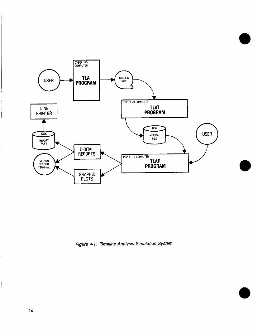
There are three separate computer programs which comprise the TLA series; TLA-3, TLAT, and TLAP. As shown in Figure 4-1, they are executed in sequence. The TLA-3 program runs on a Cyber 175 and outputs a sequential file containing a time history of workload and all associated parameters, as derived from an input mission scenario. The output file is stored on magnetic tape and referred to as the mission tape. The mission tape is read into the TLAT program which runs on a PDP 11-70 computer. TLAT converts the mission tape into a PDP 11-70 compatible format and stores the data on disk. The disk is referred to as the mission file and is utilized as input to the TLAP program which also runs on a PDP 11-70 computer. TLAP accesses the mission file based on interactive user inputs to generate graph- ical plots and tabular reports.
@ 4.2.2.1 TLA-3
TLAS is the latest version of a computer program developed by Boeing to study crew workload.
4.2.2.1.1 Scenario Structure
To utilize TLA, the analyst must first construct a scenario providing a time-based description of the mission of interest. A written description of the flight profile is usually first developed utilizing mile- stones and key events. An approximate timeline is then overlaid to reflect real world conditions, and then the scenario is segmented into phases. The following phases are normally utilized for a full mis- sion: prestart, start, taxi, takeoff, climb, cruise, descent, approach and landing, taxi, and shutdown. Within each phase, all significant events are defined (i.e., rotate, liftoff, cross outer marker, touchdown, etc.). Events do not have any effect on later statistical computation, but do aid in structuring the scenario. Events can also be inserted as markers for whatever purpose. Airplane flight manuals, opera- tions manuals, and other sources are then utilized to construct procedures to accomplish events. A procedure is a logical grouping of tasks which are selected from a catalog of up to 2000 different tasks. A task is characterized by a time duration and nine-channel activity requirements; external vision, inter- nal vision, left hand, right hand, left foot, right foot, cognition, audition, and verbal. The channel activity is expressed in terms of percent task duration time. Each task can have multiple sets of channel definitions, keyed to a reference number referred to as the situation number. Up to four different
13
-1 COMPUTER
TLAT
I n
1 PDP 11-70 COMPUTER 1
t I- REPORT
1
L T ' I hr
I \>1 11-70 COMPUTER TLAP
i PROGRAM
I ./ I I
figure 4- 1.. Timeline Analysis Simulation System
14
situations can exist for each task, to permit later comparisons of different operator concepts. Each task is keyed to a specific subsystem of the device being studied. The scenario terminology of mission, phase, event, procedure, task, situation, and subsystem has purposely been generalized to encompass workload analysis of any complex system requiring human interface.
4.2.2.1.2 Task Channel Activity
The task duration times for most control and display related tasks are analytically calculated from generic and human factors data. A primary tool in developing this data is the Boeing TX105 computer program. TX105 requires the location of all relevant controls and indicators and the origin of the coordinate system to be defined, as well as the sequence in which they are used. TX105 first computes direction cosines, horizontal and vertical deflection angles, radial angles, and straight line distance between points. Vision envelopes are computed for left eye, right eye, and both eyes for each crew member. This is dose by determining the spherical excess of spherical polygons produced by the projec- tion of cockpit windows onto a sphere with the center at the reference eye axis point, utilizing binocular and ambinocular vision. From an input sequence of tasks, specific movements are indicated. TX105 computes the angular and linear motion of each crew member to accomplish each task in sequence. Total task duration time is then calculated as the sum of the time required to look a t the control display, the time to reach the control, and the time to actuate the control or monitor the display. Looking times are computed utilizing a basic 0.66 seconds for 90-deg eye angle change. Reach times are based on empirical data giving time as a function of distance. Operating times are also empirically determined, often using time and motion studies for specific types of controls and displays. Audition and verbal channel activity is usually determined by recording the time needed to recite the required message verbatim. Some channels can be used simultaneously while others cannot. Internal and external vision are mutually exclusive, as are auditive and verbal channels. The left and right hand, and left and right foot channels can all operate simultaneously. Cognition is an independent thought processing channel that is usually allocated a fixed activity level to support each of the other channel demands.
4.2.2.1.3 TLA Processing Functions
Four basic functions are performed by TLA-3. The results of these calculations are stored on the mission tape for later input to TLAT.
The first function is task processing. The scenario is stepped through from mission start to stop time in increments referred to as the study time interval. For each task occurring during a given interval, each channel workload percentage is accumulated by ratioing the input task situation workload €or the task duration time to the study time interval. For each task situation, the visual, motor, communica- tion, and cognitive channel group workloads are summed. The weighted channel average workload is then computed as the average of the channel group workloads.
The second function is computing phase statistics. The following statistics are accumulated across all time intervals in a given phase for each channel, channel group, and weighted channel average.
1. Workload sum
2. Sum of the squares of workload
3. Mean workload
4. Workload variance
5. Workload standard deviation
15
The third function is calculating task channel activity. Each study time interval is first scanned to determine if workload for any channel exceeds the threshold. For channels that do exceed the threshold, the extent to which each task situation contributes to that overload is computed. This is done by computing the percent of interval time that each task situation contributes to the overload.
The fourth function is computing subsystem activity calculations. The purpose of these calculations is to determine how much of the time the subsystems are involved in workloads exceeding the threshold. Three different measures of subsystem activity are determined. For a given subsystem, during a given phase, the channel workloads exceeding the threshold are tagged “overload contributors’’ and total time during which these contributors exist is computed. A ratio of total channel overload contribution to total interval time, to total phase time, and to total mission time is then computed. Additional details of the TLA-3 computer program are contained in Reference 5.
4.2.2.2 TLAT
The TLAT program is utilized to convert outputs from TLA-3, which runs on a Cyber 175 computer, to a form compatible with TLAP, which runs on a PDP 11-70 computer.
The TLAT input module reads the TLA-3 mission tape which is in unformatted Cyber language in 60- bit words. Each physical record is read from the tape into an array of bytes, with 3840 bytes per record.
The TLAT output module converts the data to unformatted binary PDP 11-70 language in 32-bit real words and 16-bit integer words. Output data is stored in separate direct access files of up to 610 words for each crew member.
4.2.2.3 T U P
The TLAP program enables the analyst to interactively select options from a series of menus on a Vector General computer graphics terminal of a PDP 11-70 computer. Initial evaluation of TLA results can be made by viewing the graphics display on the terminal. A series of tabular and graphic reports can then be interactively constructed and printed out. This procedure was followed in generating the crew tasking data shown in the results of Section 7.
4.2.3 Airplane Type Data Base Selection
This study investigated crew tasking in both conventional and advanced air transport flight decks.
An integral part of the TLA computer program is the data base containing crew procedures and tasks. To minimize program expense, a study guideline was established to utilize existing data bases as much as possible. A review of available data bases was conducted and it was determined that the 737- 100 flight deck data base was the most suitable for analysis of the conventional flight deck, taking all factors into account. It was similarly determined that the NASA Transportation Systems Research Vehicle (TSRV) Aft Flight Deck data base was the most suitable for analysis of the advanced flight deck.
Relevant details of these two flight deck configurations are included in the discussion of scenarios in Sections 5.1.2.1 and 5.1.2.2.
4.3 DEVELOPMENT OF FLIGHT OBJECTIVES
In this section, the methodology and rationale for developing the TLA scenarios is discussed.
16
Flight objectives were specified which define types of flight conditions or aircraft operating require- ments which are then utilized in developing the scenarios. The flight objectives were generic so that both conventional and advanced flight deck concepts could be implemented to satisfy each flight objec- tive in both current NAS and future NAS environments.
The following flight objectives were selected to address the study problem areas previously discussed in Section 4.1.
1. Receiving an ATC vector
2. Receiving a vector toward an undesirable weather condition
3. Pilot requested weather data
4. Receiving an ATC advisory of pilot-reported windshear
5. Receiving a new routing to a holding fix
6. Acknowledging a clearance and intent to comply
7. Receiving a TCAS traffic alert in the terminal area
8. Responding to a resolution advisory in the terminal area
17
5.0 SCENARIO DESCRIPTION
In keeping with the study guideline of utilizing existing data bases as much as possible, it was determined that the Atlanta terminal area was the most suitable scenario location. A previous Atlanta TLA data base was updated, based on current terminal area procedures, constraints, and geometry. Published instrument arrival and approach procedures as well as ATC facility letters of agreement were accommodated.
Consideration of the flight objectives discussed in Section 4.3, along with the expectation of relatively high workload in the terminal area, resulted in the selection of an Instrument Landing System (ILS) approach to Atlanta as the basis for developing scenarios.
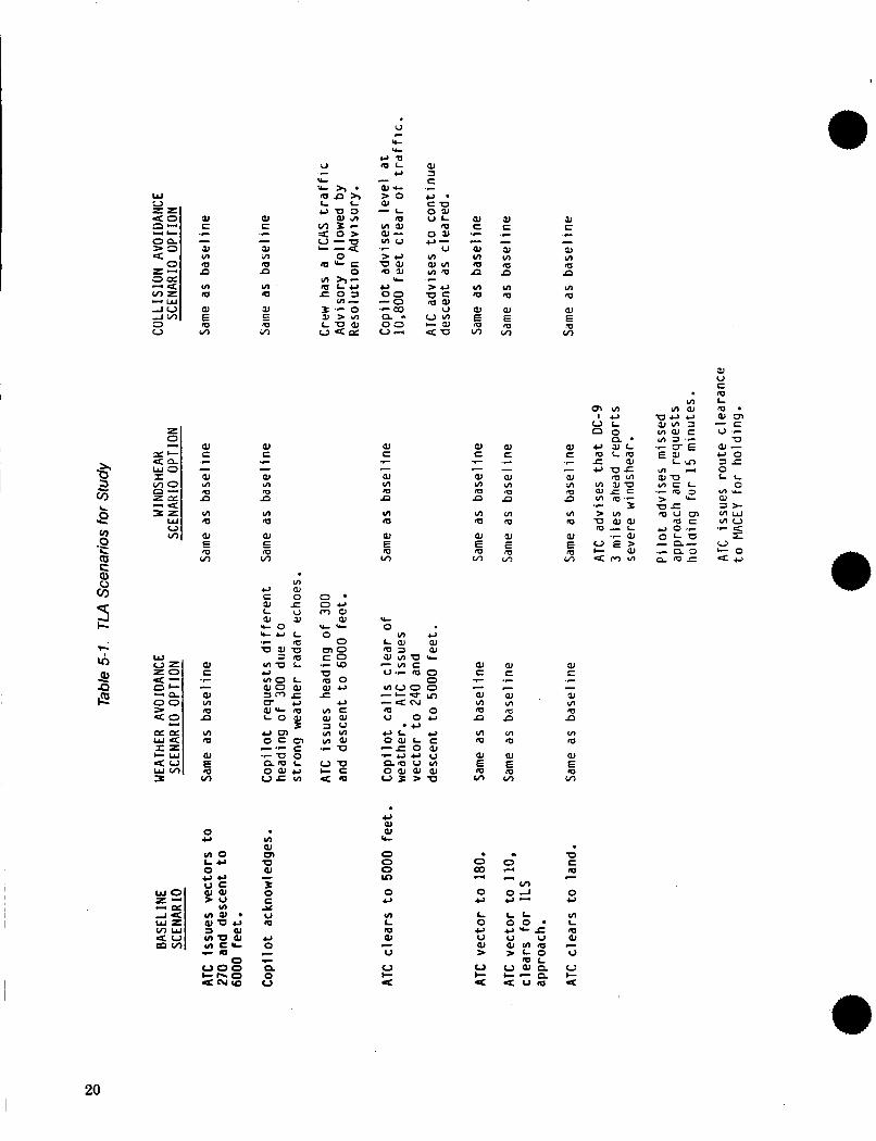
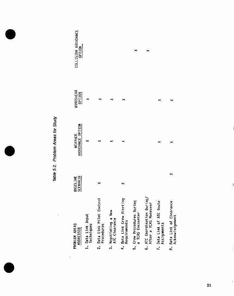
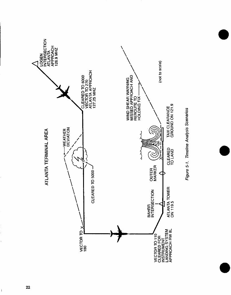
Four basic scenarios were developed to accommodate the flight objectives of Section 4.3. They all began at the point where a typical air carrier arrival is handed off from Atlanta Center to Atlanta Approach Control. ‘hble 5-1 describes the scenarios in summary form, and Table 5-2 correlates each scenario with the specific problem areas addressed. The lateral flightpath for each scenario is illustrated in Figure 5-1. The following sections describe the scenarios in detail.
5.1 NORMAL ILS APPROACH
This scenario was intended to be representative of a tactical ATC environment where traffic was sequenced into a conventional traffic pattern for merging onto the final approach course. This was based on the expectation that ground-based computer automation would assist the controller in selecting and sending tactical as well as strategic clearances via Mode-S data link.
5.1.1 Flight Plan and ATC Procedures
The normal ILS approach scenario was based on nominal 737 flight performance for a typical arrival from the northeast landing on runway eight left a t the Atlanta Hartsfield Airport. The scenario re- flected current Atlanta airspace configuration and ATC operating procedures.
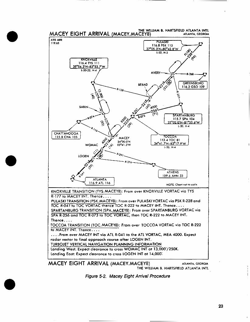
Initial assumptions for the scenario were that Atlanta Center has assigned the MaceyS Arrival (fig. 5-2), cleared the flight for descent to 11,000 ft with instructions to cross Logen Intersection at 250 kn at 14,000 ft, and to contact Atlanta Approach at Logen.
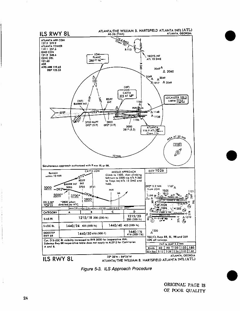
The scenario began with this handoff at Logen. The airplane continued descent on the 041-deg radial of the Atlanta VOR until approach issued a vector to sequence the flight downwind into the ILS arrival traffic, and issued a new altitude constraint of 6,000 ft. The flight was then handed off to the Atlanta final approach controller, who subsequently issued a 5,000-ft altitude limit. A vector was then issued for the base leg, followed by another vector to intercept the final approach course about 13 miles from the runway. Clearance for an ILS runway 8L approach (fig. 5-31 was issued with instructions to contact Atlanta Tower a t Bahrr Intersection. After crossing Bahrr, the tower issued landing clearance, and advised that the flight was number three for landing following a DC-9 3 mi ahead. During landing rollout, the tower handed off the flight to Atlanta ground control, who then issued taxi instructions to the ramp. The scenario ended as the airplane exited the runway.
5.1.2 Crew Procedures
Procedures were developed that were representative of today’s operations in a tactical ATC environ- ment where full automatic flight would be difficult due to unforeseen ATC constraints. A higher level of automation in the advanced flight deck was provided in the scenarios by assuming pilot control via the
aJ a c
a J c 5 3 aJ - L
m V I Y aJ- v)v > 3 UaJ m a
.r
v-
W
al c .e
Y c .C
SI c c -
Y m 5 n ul m
- Y m m n
5c , U C m a
v) m
Y V C m L
m m 5 * aJm - C v 'e
1 4 2 U L n n
a C c
J aJ- e o 0 L L 0
aJ
a x
m Y -
a >
W C .c
01 C c
aJ C .c
aJ t -
0) m 5 n
0) m 5 n
aJ m 5 n
0) m 5 n
m m
m m
0)
v) E
aJ E 5 m
Y
E m
W U T aJ
C a J a J c c - .r
aJ C .C
c aJ m m n m 0 v 0 0
= u v ) m m m
m m
u aJ 0, (c
0 u ul
0 0 0 v)
0 U
v) L rn 0,
W c
20
x x
x x
x Y
E P Q
B
P d Q
x
x x
- 0 L
m c 42 L aJ 4:
.r
c
Crr C
W u c
aJ e, 3 0 CT
V c
e, c 0 V
.r L
L L) u
0 c .C n
5 n C c(
II)
3 W LV) v u c Y a J
A L
ucT m a J
.E !5 - m a
n a
a w c a .- 0- A- c aJ
5 0 u o 5 L nn L
v m
21
$ \ \ \ \ \
3 0 0 0 In
e
Y
O W LI a
0
22
THE WILLIAM 8. HARTSFIELD ATLANTA INTL ATLANTA, GEORGIA AACEY EIGHT ARRIVAL fMACEY.MACEY8)
ATIS ARR 119.65
116.2 GSO 109
1-20, H-4
113.4 TOC 81 34°41.7'N-83017.9'W
L-20. H-4 a -
NOTE: Chart not lo scale
KNOXVILLE TRANSITION (TYS.MACEY8): From over KNOXVILLE VORTAC via TYS R- 177 to MACEY INT. Thence. . . . PULASKI TRANSITION (PSK.MACEY8): From over PULASKI VORTAC via PSK R-228 and TOC R-041 to TOC VORTAC thence TOC R-222 to MACEY INT. Thence.. . . SPARTANBURG TRANSITION (SPA.MACEY8) : From over SPARTANBURG VORTAC via SPA R-256 and TOC R-073 to TOC VORTAC, then TOC R-222 to MACEY INT. Thence .... TOCCOA TRANSITION (TOC.MACEY8): From over TOCCOA VORTAC via TOC R-222 to MACEY INT. Thence.. . . . . . .From over MACEY INT via ATL R-041 to the AT1 VORTAC, MEA 4000. Expect radar vector to final approach course after LOGEN INT. TURBOJET VERTICAL NAVIGATION PLANNING INFORMATION landing West: Expect clearance to cross WOMAC INT at l3,000'/250K. Landing East: Expect clearance to cross LOGEN INT at 14,000:
MACEY EIGHT ARRIVAL (MACEY.MACEY8) ATLANTA, GEORGIA
THE WILLIAM 8. HARTSFIELD ATLANTA INTL
Figure 5-2. Macey Eight Arrival Procedure
23
ATLANTA/THE WILLIAM B. HARTSFIELD ATLANTA INTL (ATL) AL-26 (FAA) ATLANTA, GEORGIA ILS RWY 8L . I .
I
1440/50 416 (500-1) SIDESTEP RWY 8R
COT. D SLOC 8L viribilify increased to RVR 5000 for inoperotive MM. Sidestep Rwy 8R inoperotive toblo does not opply to ALSF-2 for Cot-lories A ond B.
TDZ/CL Rwys 8R. 8L. 9R ond 26R HlRL oll runwoys -
FAF to MAP 5.2 NM Knots I 60 I 90 I 1 2 0 1150 1180
Min:Secl 5:12 I 3:28 I2:36 12:05 I1:44 I
33' 3 8 " - 84.26'W ATLANTA, GEORGIA ILS RWY 8L ATLANTA/THE WILLIAM 8. HARTSFIELD ATLANTA lNTL (ATL)
,JUNTA APP CON 27.9 379.9 ,TLANTA TOWER 19.1 257.6 ;ND CON 21.9 348.6 :LNC DEL 21.63 SR a
ARR 119.63 DEP 125.55
w 2049 A
A 2060 /y .:; .... , ... ... :: ;.;>,
' 2049
A1917 A2049
h I 5000 ATLANIA-
2810 (5.5) 116 9 A1L.C..
092' (3.9) 092' (2.9)
Chon 116
10 N
Smuhonwus opprooch outhonted wlth R wys 9L or 9R. . .
ELEV 1026 ] MlSStD APPROACH Rcmoin within 10 NM
/ RElFF I to Trow Int/ATL 15 DME ond I
Figure 5-3. ILS Approach Procedure
ORIGINAL PAGE IS OE POOR QUALITY
24
autopilot mode control panel, while conventional flight deck scenarios assumed a more basic hand flying task.
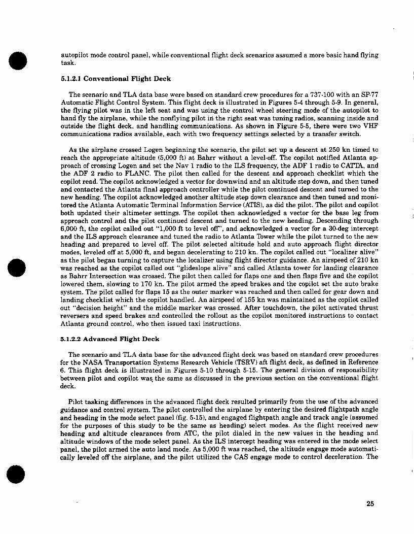
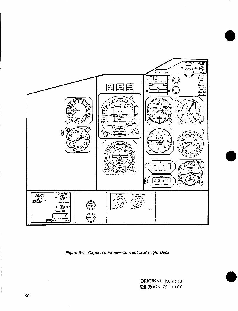
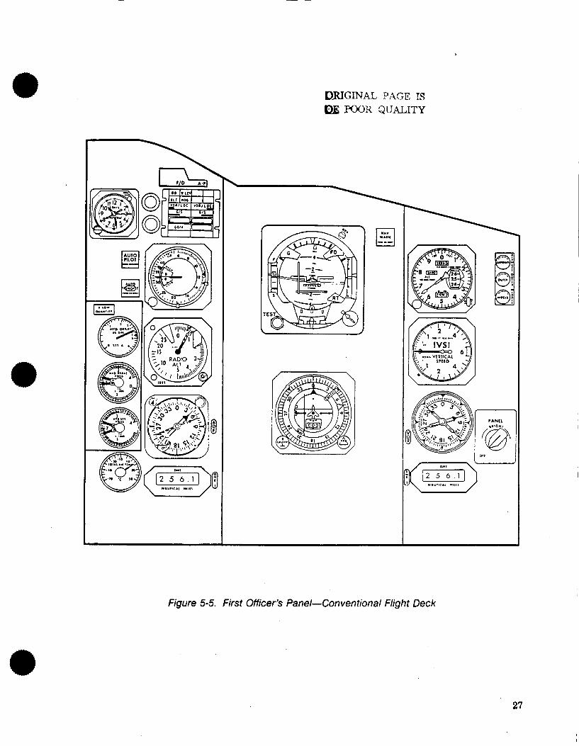
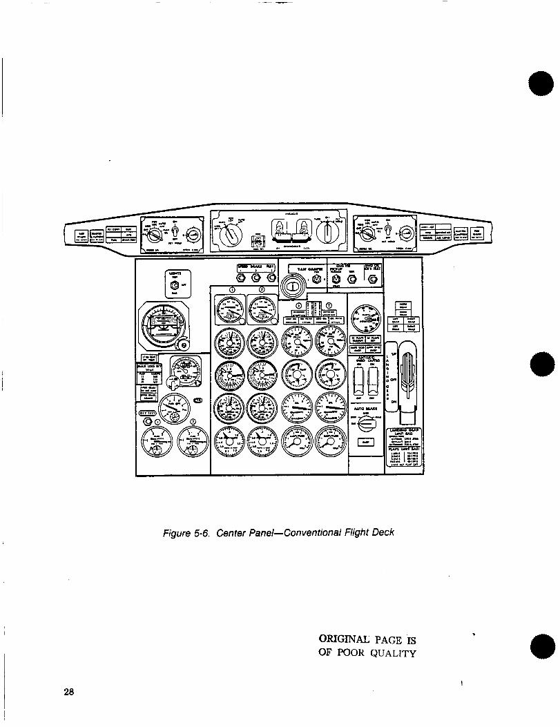
5.1.2.1 Conventional Flight Deck
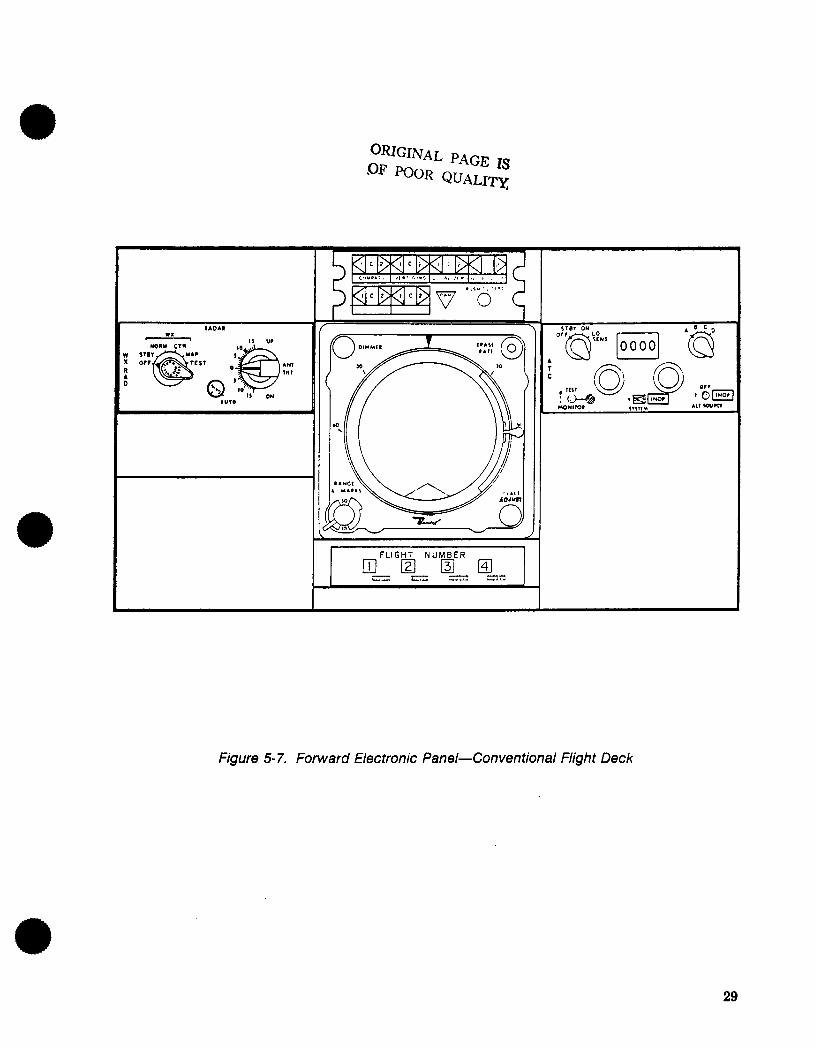
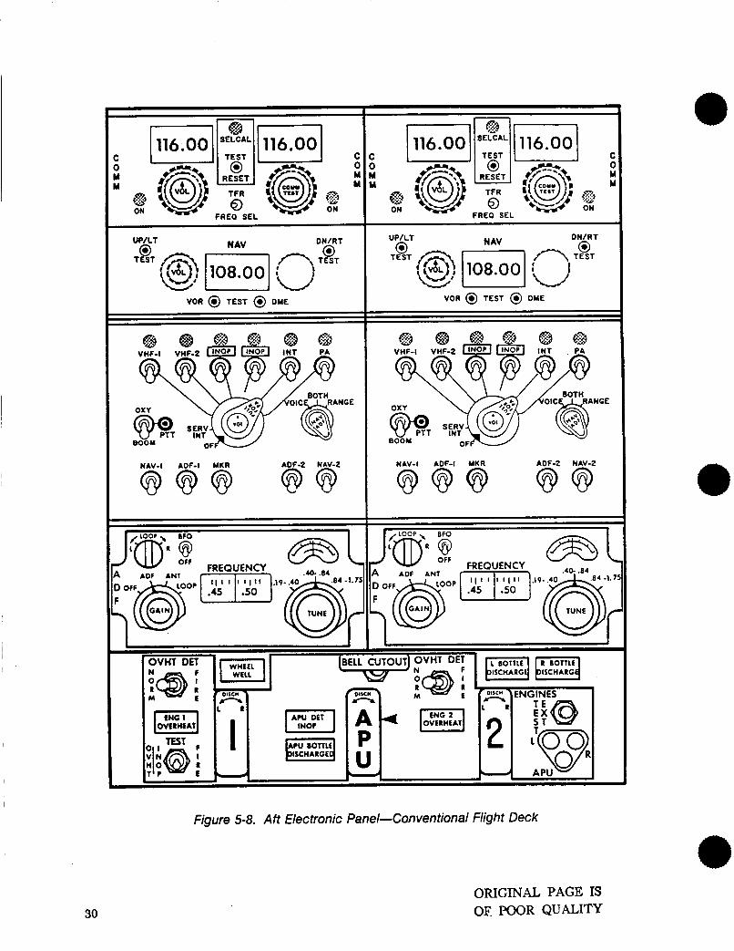
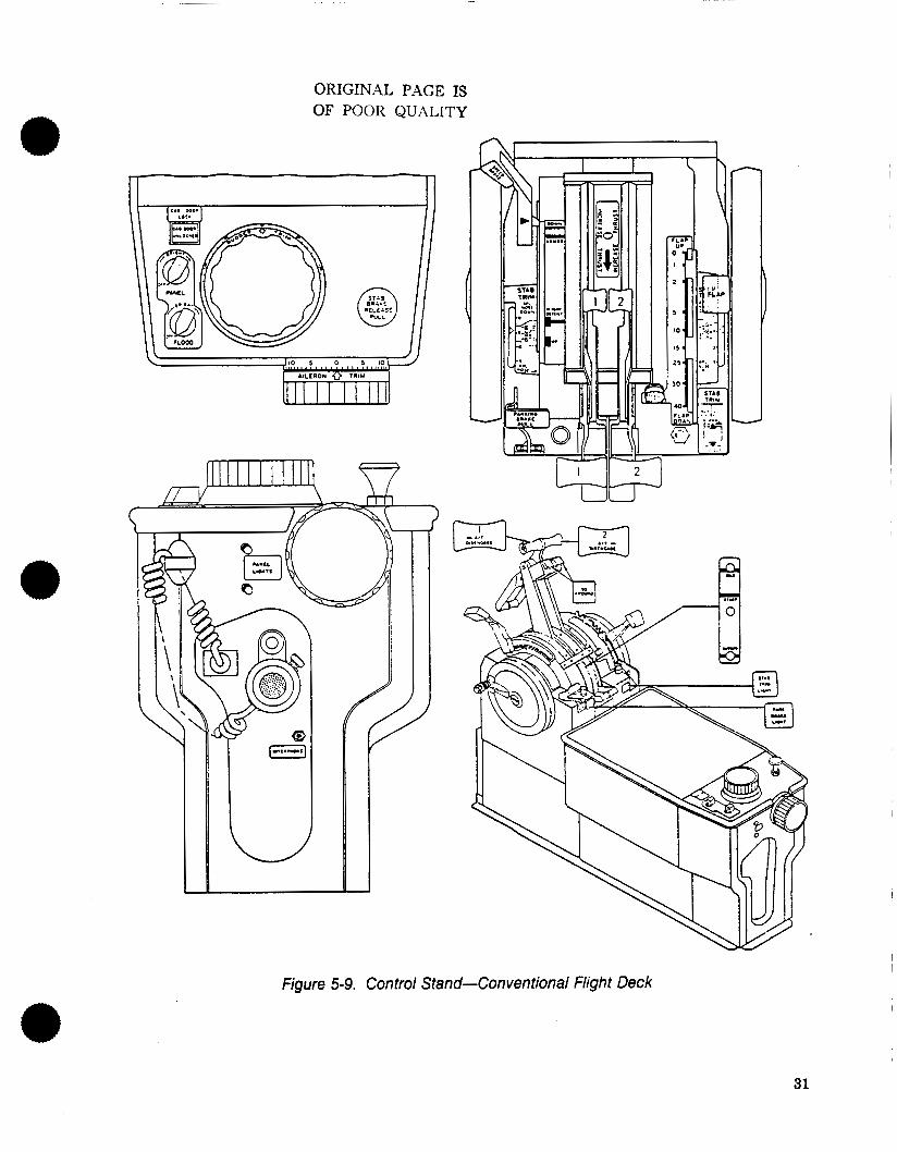
The scenario and TLA data base were based on standard crew procedures for a 737-100 with an SP-77 Automatic Flight Control System. This flight deck is illustrated in Figures 5-4 through 5-9. In general, the flying pilot was in the left seat and was using the control wheel steering mode of the autopilot to hand fly the airplane, while the nonflying pilot in the right seat was tuning radios, scanning inside and outside the flight deck, and handling communications. As shown in Figure 5-5, there were two VHF communications radios available, each with two frequency settings selected by a transfer switch.
As the airplane crossed Logen beginning the scenario, the pilot set up a descent a t 250 kn timed to reach the appropriate altitude (5,000 ft) at Bahrr without a level-off. The copilot notified Atlanta ap- proach of crossing Logen and set the Nav 1 radio to the ILS frequency, the ADF 1 radio to CATTA, and the ADF 2 radio to FLANC. The pilot then called for the descent and approach checklist which the copilot read. The copilot acknowledged a vector for downwind and an altitude step down, and then tuned and contacted the Atlanta final approach controller while the pilot continued descent and turned to the new heading. The copilot acknowledged another altitude step down clearance and then tuned and moni- tored the Atlanta Automatic Terminal Information Service (ATIS), as did the pilot. The pilot and copilot both updated their altimeter settings. The copilot then acknowledged a vector for the base leg from approach control and the pilot continued descent and turned to the new heading. Descending through 6,000 ft, the copilot called out “1,000 ft to level off’, and acknowledged a vector for a 30-deg intercept and the ILS approach clearance and tuned the radio to Atlanta Tower while the pilot turned to the new heading and prepared to level off. The pilot selected altitude hold and auto approach flight director modes, leveled off a t 5,000 ft, and began decelerating to 210 kn. The copilot called out “localizer alive” as the pilot began turning to capture the localizer using flight director guidance. An airspeed of 210 kn was reached as the copilot called out “glideslope alive” and called Atlanta tower for landing clearance as Bahrr Intersection was crossed. The pilot then called for flaps one and then flaps five and the copilot lowered them, slowing to 170 kn. The pilot armed the speed brakes and the copilot set the auto brake system. The pilot called for flaps 15 as the outer marker was reached and then called for gear down and landing checklist which the copilot handled. An airspeed of 155 kn was maintained as the copilot called out “decision height” and the middle marker was crossed. After touchdown, the pilot activated thrust reversers and speed brakes and controlled the rollout as the copilot monitored instructions to contact Atlanta ground control, who then issued taxi instructions.
e
5.1.2.2 Advanced Flight Deck
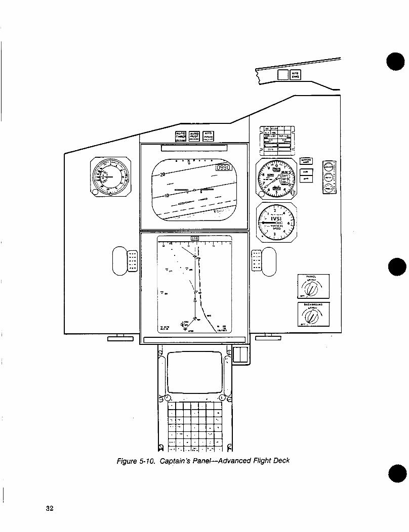
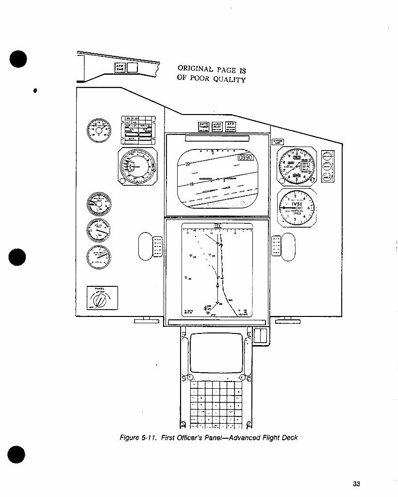
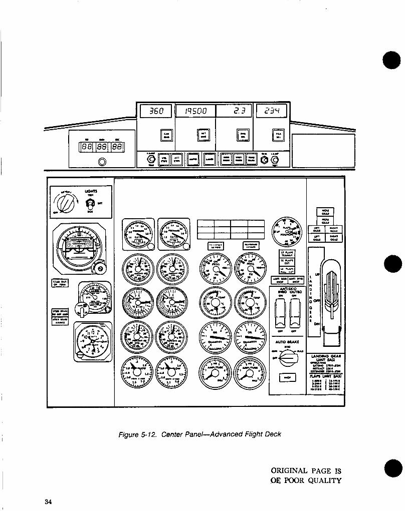
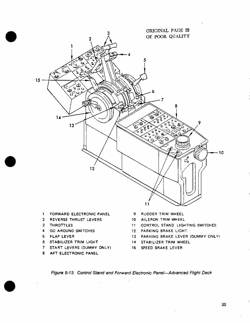
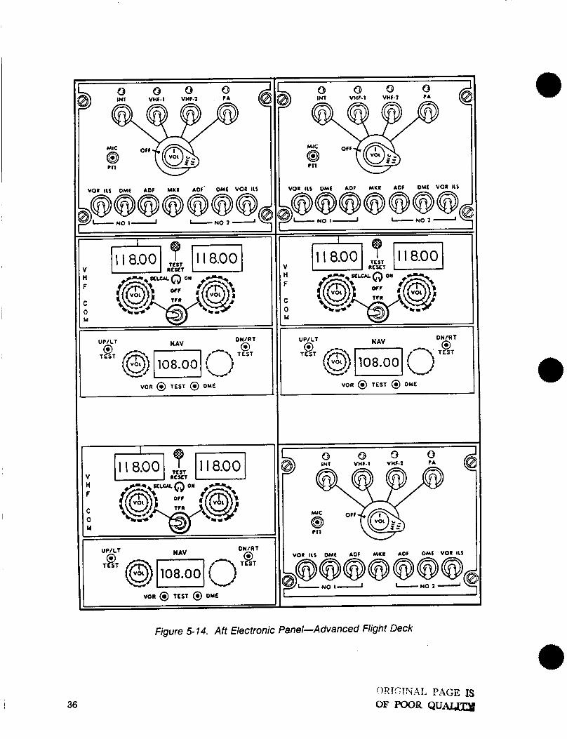
The scenario and TLA data base for the advanced flight deck was based on standard crew procedures for the NASA Transportation Systems Research Vehicle (TSRV) aft flight deck, as defined in Reference 6. This flight deck is illustrated in Figures 5-10 through 5-15. The general division of responsibility between pilot and copilot was the same as discussed in the previous section on the conventional flight deck.
Pilot tasking differences in the advanced flight deck resulted primarily from the use of the advanced guidance and control system. The pilot controlled the airplane by entering the desired flightpath angle and heading in the mode select panel (fig. 5-15), and engaged flightpath angle and track angle (assumed for the purposes of this study to be the same as heading) select modes. As the flight received new heading and altitude clearances from ATC, the pilot dialed in the new values in the heading and altitude windows of the mode select panel. As the ILS intercept heading was entered in the mode select panel, the pilot armed the auto land mode. As 5,000 ft was reached, the altitude engage mode automati- cally leveled off the airplane, and the pilot utilized the CAS engage mode to control deceleration. The
25
c
Figure 5-4. Captain's Panel-Conventional Flight Deck
ORIGINAL PAGE IS W I W l R QiJALITY
26
DRIGINAL, PAGE 1s FQOk QUALITY
Figure 5-5. First Officer's Panel-Conventional Flight Deck
27
28
Figure 5-6. Center Panel-Conventional Flight Deck
ORIGINAL PAGE IS OF POOR QUALITY
.
I
I A D A I
FLIGHT NUMBER B o _ o _ o g _ l
Figure 5-7. Forward Electronic Panel-Conventional Flight Deck
29
-
C 0 M
C 0
Y
(g¶ Y
ON FREQ SEL
ON
VOR @ TEST @ DYE
@31 .40. .e4 FREQUENCY
C 0 M M
VOR @ TEST @ OME
NAV-I ~~~ ADF-I UKR @ 2 @
Figure 5-8. Aft Electronic Panel-Conventional Flight Deck
30 ORIGINAL PAGE IS OF POOR QUALITY
ORIGINAL PAGE IS OF POOR QUALITY
Figure 5-9. Control Stand-Conventional F/ight Deck
31
/
Figure 5-1 0. Captain's Panel-Advanced Flight Deck
32
ORIGINAL PAGE rs OF POOR QUALITY
@) s ..e-
'?, ,; , ,/;'
a- II
-.- D
Figure 5-1 1. First Officer's Panel-Advanced Flight Deck
33
I
Figure 5- 12. Center Panel-Advanced Flight Deck
ORIGINAL PAGE IS Ol3 POOR QUALITY
34
15
c) ORIGINAL PAGE IS
10
FORWARD ELECTRONIC PANEL 9 RUDDER TRIM WHEEL REVERSE THRUST LEVERS 10 AILERON TRIM WHEEL THROlTLES 11 CONTROL STAND LIGHTING SWITCHES GO AROUND SWITCHES 12 PARKING BRAKE LIGHT FLAP LEVER 13 PARKING BRAKE LEVER (DUMMY ONLY) STABILIZER TRIM LIGHT 14 STABILIZER TRIM WHEEL START LEVERS (DUMMY ONLY) 15 SPEED BRAKE LEVER AFT ELECTRONIC PANEL
Figure 5- 13. Control Stand and Forward Electronic Panel-Advanced Flight Deck
35
I W
I VOR @ TEST @ OM€
I 1
A@- I
W I
VOI I l S OMf
36
Figure 5-1 4. Aft Electronic Panel-Advanced Flight Deck
0RIC;1NA4L PAGE IS OF POOR QU-
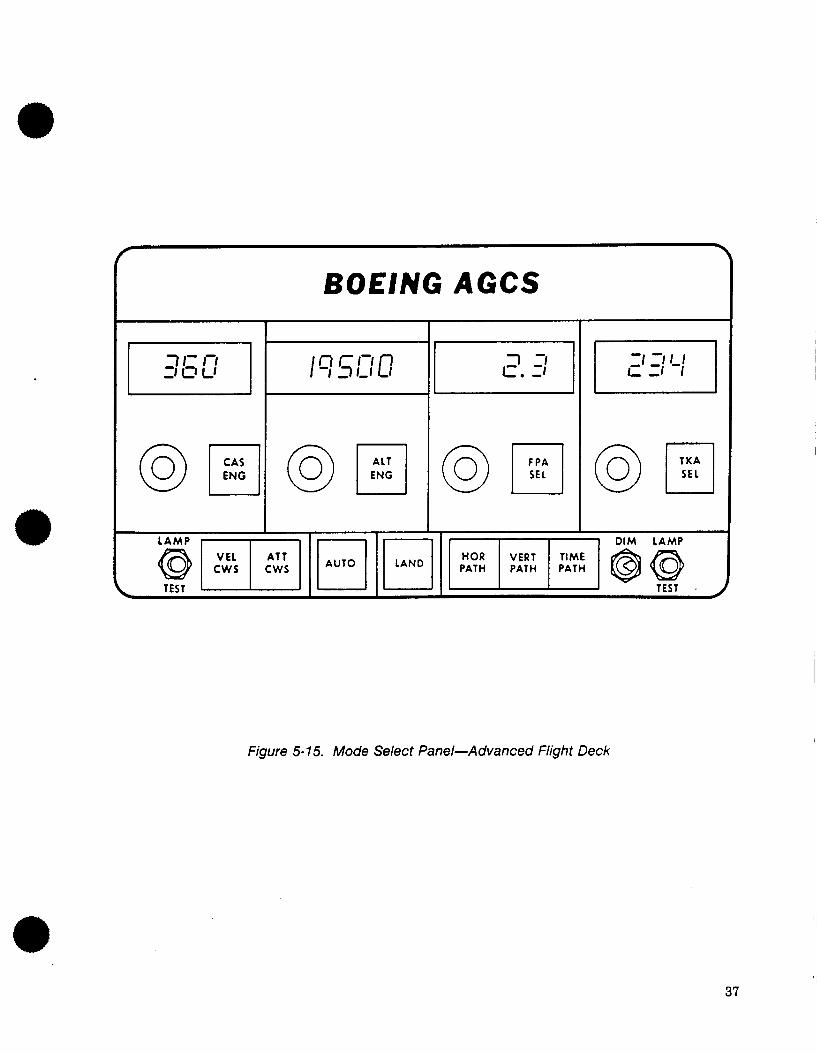
BOEING AGCS
I I i DIM LAMP
Figure 5- 15. Mode Select Panel-Advanced Flight Deck
37
localizer and then glideslope were automatically captured in auto land, and the airplane continued to decelerate, with the pilot calling out “flaps one” and “flaps five” to the copilot. Speed brakes and auto brakes were set as in the conventional flight deck, and flaps 15, gear down, and landing checklist were accomplished. Touchdown and rollout were performed automatically in the auto land mode, which disen- gaged at 30 kn when the pilot took over manually.
Copilot tasking in the advanced flight deck was very similar to that in the conventional flight deck, as discussed in the previous section.
5.1.3 Incorporation of Data Link in Scenarios
The normal ILS approach scenarios for the conventional and advanced flight decks were modified to incorporate Mode-S data link implementation. The previously described copilot tasks associated with communications using VHF’ voice were replaced with data link tasks as described in Section 6 which defines the flight deck concepts utilized for data link. The previously described pilot tasks associated with VHF voice communication were limited to aural monitoring of incoming messages. Section 6 defines a communications management system concept for conventional flight decks and an information management system concept for advanced flight decks which included pilot visual as well as aural tasks associated with annunciating receipt of an incoming message but did not require the pilot to read the message directly. The copilot task of clearance readback in the VHF voice scenarios was replaced by the copilot reading the clearance out loud to the pilot from the data link CDU. Another feature distinguish- ing the VHF voice scenarios from the data link scenarios was elimination of the requirement to estab- lish contact with each new ATC sector after an ATC handoff. This was based on a study assumption that monitoring of each new ATC sector VHF voice frequency would suffice, rather than actually calling each new sector controller.
5.2 ILS APPROACH WITH WEATHER DEVIATION
This scenario was designed to illustrate a more interactive type of communication between the pilot and ATC. A variety of circumstances could require similar pilot requested clearance changes.
5.2.1 Current NAS
This scenario was identical to the normal ILS scenario except for a flightpath deviation around severe weather. When Atlanta Approach Control issued the first vector to turn the flight downwind, the crew noted strong weather echoes in that direction and requested an alternative heading that would avoid the weather. Approach agreed to the new heading, and the crew advised they would call when clear of the weather. After approximately two minutes, the copilot advised approach that they were clear and approach issued another vector to return the flight to the nominal arrival stream.
In the conventional flight deck version of this scenario, the pilot continued to hand fly the airplane using the autopilot control wheel steering mode as the vectors around the weather were followed.
In the advanced flight deck version of the scenario, the pilot continued to fly the airplane by input- ting and engaging new headings in the mode select panel heading window.
5.2.2 Mode-S Data Link
Data link capabilities were provided in the scenarios to enable the crew to format and send a downlink request for the desired heading around the weather. A variety of requests could be handled in this manner.
38
5.3 ILS MISSED APPROACH WITH REROUTE
This scenario was designed to illustrate the transfer of a high priority message along with a detailed route assignment.
e 5.3.1 Current NAS
This scenario was identical to the normal ILS scenario except for the final portion of the approach from the outer marker inbound. After crossing the outer marker, Atlanta Tower advised the flight that the DC-9 3 mi ahead had just reported severe windshear. The pilot decided to execute a missed approach and called for flaps 15 and gear up as he initiated a go-around. In the VHF voice implementation, the pilot called the tower advising of the missed approach and requested holding instructions while the copilot reconfigured the airplane.
In the advanced flight deck, the new route to the holding fix issued by Atlanta Tower was entered in the navigation computer and then lateral (LNAV) and vertical (VNAV) path modes were engaged. With- out data link, the copilot manually keyed in the new route using the FMC CDU. For study purposes, the TSRV navigation computer was assumed to have three functions similar to those of the Boeing 757/767 allowing new waypoint definition, direct-to-waypoint navigation, and holding pattern definition. Copilot tasks in the VHF voice scenario for these three procedures were borrowed from the 7571767 Operations Manual.
5.3.2 Mode-S Data Link
In the data link implementation, the copilot handled communications while reconfiguring the air- plane. In the conventional flight deck, the only other difference between VHF voice and data link scenarios other than the basic data link concepts themselves was that the copilot wrote down the clearance on paper with VHF voice, while the data link scenario permitted the copilot to produce a hard copy of the clearance on the cockpit printer.
In the advanced flight deck. the new route was automatically entered into the navigation computer as an updated temporary flight plan, eliminating the need to manually key in the route using the FMC CDU.
5.4 ILS APPROACH WITH TCAS ENCOUNTER
This scenario was identical to the normal ILS scenario except for a TCAS encounter which began about 1 min after the flight turned to the downwind heading issued by approach control. The TCAS portion of the scenario began with an aural and visual annunciation of a TCAS traffic advisory, while the flight (own aircraft) was descending out of 10,500 ft a t 900 ft per minute, see Figure 5-16. As shown, the intruder airplane was climbing out of 9,200 ft at 857 f t per minute. A head on encounter giving a closure rate of 440 kn was assumed. For study purposes, the intruder aircraft was assumed to be VFR and Mode-C transponder equipped, which along with the speed and altitude could be representative of a light piston twin-engine general aviation aircraft.
Both pilot and copilot monitored the aural and visual master caution, and monitored the visual alert display indicating TCAS ALERT. The TCAS traffic display simultaneously appeared on the weather radar indicator (conventional flight deck) or the EHSI (advanced flight deck) using the 5-nmi TCAS- range scale which was preselected by the copilot during the descent checklist. Both pilots scanned outside the airplane and monitored the TCAS traffic display, while the copilot called out two successive traffic reports of the intruders relative altitude, altitude rate, and bearing to the pilot. Fifteen seconds after the annunciation of the traffic advisory, the pilot and copilot monitored the aural and visual
39
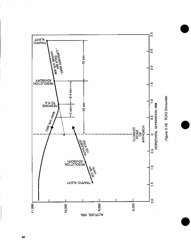
40
master warning for the TCAS resolution advisory, and also the time critical aural warning of TCAS CLIMB CLIMB CLIMB. The pilot decided to respond to the TCAS CLIMB 7.6 sec after its initiation, while monitoring the TCAS traffic display and the time critical IVSI display. The copilot monitored the TCAS traffic display and called out another traffic report on the intruder, and the pilot disengaged the autopilot, visually cleared the airspace, and initiated a climb. As the climb began, the pilot instructed the copilot to continue monitoring the intruder and to call approach control. Twenty seconds after annunciation of the RA, the copilot noted the intruder had passed 750 f t underneath them and called out clear of conflicting traffic, as the pilot leveled off a t 10,800 ft. The copilot called Atlanta Approach, advising they were level a t 10,800 due to a TCAS R4, and requested further clearance. Atlanta Ap- proach cleared for continued descent, a t which time the pilot re-engaged the autopilot.
41
6.0 DEFINITION OF FLIGHT DECK CONCEPTS
This section presents concepts for implementation of Mode-S data link and TCAS in conventional and advanced flight decks.
6.1 MODE-S DATA LINK
This description of data link implementation correlates with Section 5 descriptions of data link crew procedures.
6.1.1 Controls and Displays (Conventional and Advanced)
Advanced and conventional flight deck equipped aircraft have commonly used a CDU pilot interface for FMC or ACARS systems. This study used a similar means of pilot interface for data link control and display.
6.1.1.1 CDU Configuration
The CDU concept chosen for implementation of Mode-S Data Link was based on the Teledyne Interac- tive Display Unit (IDU) currently utilized by several airlines for crew interface with the ACARS system. The IDU performed the role of a Multifunction CDU, as defined in ARINC Characteristic 739. The IDU protocol was designed to allow multisystem access to the IDU. When the IDU was initially powered up, it established contact with each system connected to it. Then the IDU displayed the main menu of the priority system, assumed to be Mode-S Data Link for this study. The main menu for data link is illus- trated in Figure 6-1. When the RETURN key was pressed from this menu, the IDU displayed the established system menu, allowing access to other systems such as ACARS.
6.1.1.1.1 Keypad Concept
There were no hard keys on the IDU, rather menus and keyboards drawn on the display. Keys were activated by touching them on the display surface. An infrared LED matrix was used to detect touches on the screen. When a key was touched on the IDU, the key would highlight in reverse video. Releasing the key when it was highlighted activated the key. The IDU was capable of displaying 294 alphanu- meric characters on 14 lines with 21 characters per line.
6.1.1.1.2 Uplink Message Display
Figure 6-1 illustrates the main data link menu which was normally displayed. Selection of any item would bring up the next relevant display page. For example, selection of ATC UPLINKS PENDING, which flashed upon receipt of an ATC uplink until acknowledged, resulted in a display similar to Figure 6-2. The newly received uplink was then displayed, with END OF MESSAGE delineating the end of text and with the appropriate acknowledgment options at the bottom of the page. Note that as shown in the figure, UNABLE was always included as an option for the pilot to respond to an uplinked clearance. If the uplink was of an advisory nature, such as the ETIS (Enhanced Terminal Information Service) report shown in Figure 6-3, then the acknowledgment was only for onboard system control purposes such as to route a message to the printer, since confirmation of intent to comply was not required.
6.1.1.1.3 Downlink Message Composition
Figure 6-4 illustrates initiation of a downlink. Selection of REQUEST FOR CLEARANCE brought up a choice of pilot-requested clearances. Selection of MAKING A MISSED APPROACH, Figure 6-5, brought up a display prompting the pilot for additional information required to make the downlink
43
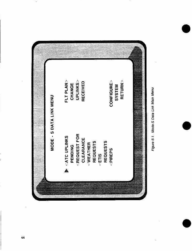
44
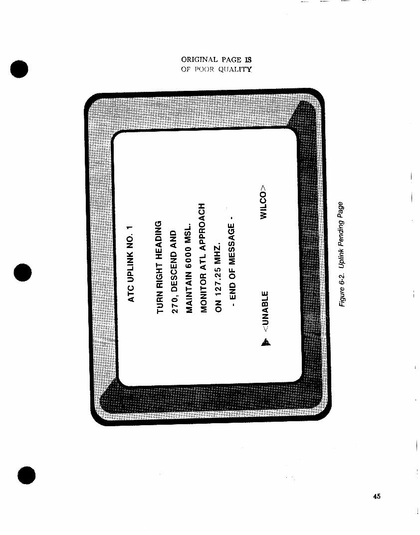
ORIGINAL PAGE IS OF POOR QUALITY
45
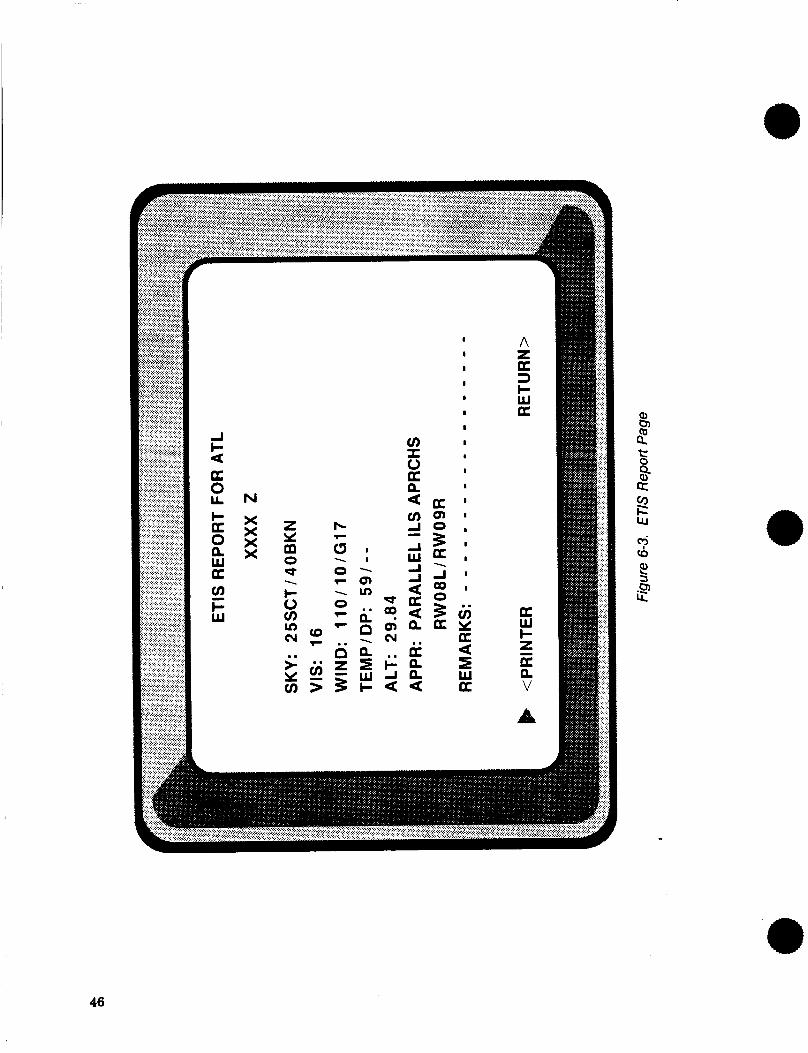
J l-
U 0 LL I- K 0 P, W K u)
W
a
F
46
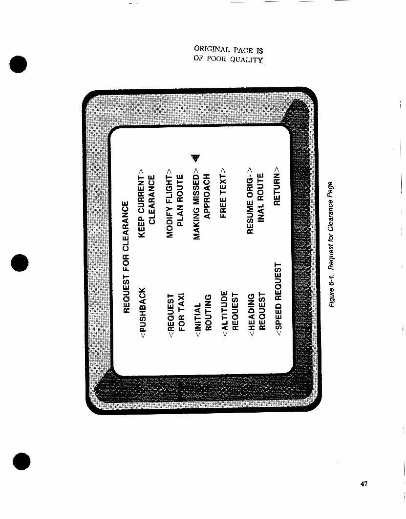
W 0 z a a a
a
w J o 0 L I- tn w 3 0 w a
ORIGINAL PAGE IS OF POOR QUALITY
A c x w c w W
L a
W I -
5 3 E z J U
V a a
A z K 3 c W K
c tn w 3 a w a n
n W w v) V
47
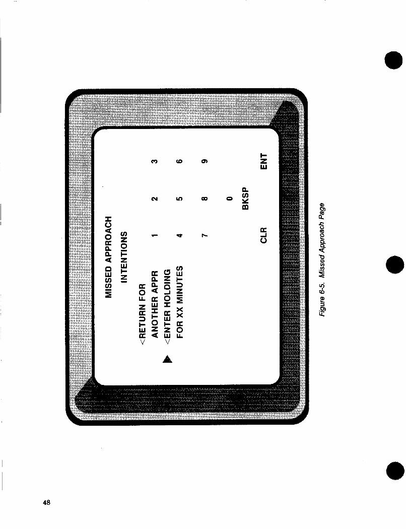
(3 cc)
cv v)
.- d
n 00 O Y
m cn
cc
48
complete, based on knowledge of ATC procedures. As shown, a numerical keypad was displayed along with a choice of pilot intentions for the missed approach. First, the desired values were entered in the appropriate data fields using the keypad, then the desired selection was made causing the entire downlink to be automatically formatted and sent, based on the previous series of CDU page selections and entries.
6.1.1.1.4 Tasking Assumptions
In keeping with the study guideline of utilizing existing data to the extent possible, the tasking definition (i.e., vision, motor, and cognitive activity) for the forward-mounted FMC CDU (located be- tween the knees of each pilot in the advanced flight deck) was utilized for the data link IDU as well. The tasking results for data lihk usage based on this assumption were expected to be representative of a CDU location forward of the throttles and near the pilot’s knee.
6.1.1.2 Printer Installation
A printer was assumed to be installed in the flight deck. No crew tasks associated with retrieval of hard copy from the printer were defined, only the tasks to route messages to the printer were included. Its presence in the flight deck was only to illustrate a possible method of producing a hard copy when acknowledging an uplink.
6.1.2 Conventional Flight Deck Interfaces
In keeping with the general level of technology utilized in conventional flight deck aircraft, the data link system was implemented as independent from other aircraft systems.
6.1.2.1 Autopilot Interface * The conventional flight deck data link implementation did not interface with the autopilot.
6.1.2.2 Communication Management System
Normal Mode-S data link system operation was annunciated by the communication management system. Crew attention was initially captured by an aural sound unique to the communication manage- ment system. This aural directed crew attention to the Communication Management Visual Display. This display was located within the primary field of view of each pilot, and annunciated 1) the specific communication subsystem requiring attention, and 2) the level of urgency required. The specific subsys- tem was displayed by alphanumerics, i.e., MODE-S UPLINK PENDING, with the level of urgency encoded by the color of the display. Normal messages, such as standard ATC clearances, were annunci- ated in green. Higher urgency messages, such as severe weather warnings, were annunciated in reverse video. Viewing MODE-S UPLINK PENDING on the communication management display directed crew attention (assumed to be only the copilot in this study) to the data link CDU where the ATC UPLINKS PENDING selection was flashing on the main data link menu. Figure 6-6 illustrates the assumed location for the communication management display.
6.1.3 Advanced Flight Deck Interfaces
It was assumed that a digital data bus in the advanced flight deck would provide a means of data transfer between the data link system, the FMC, and the autopilot.
49
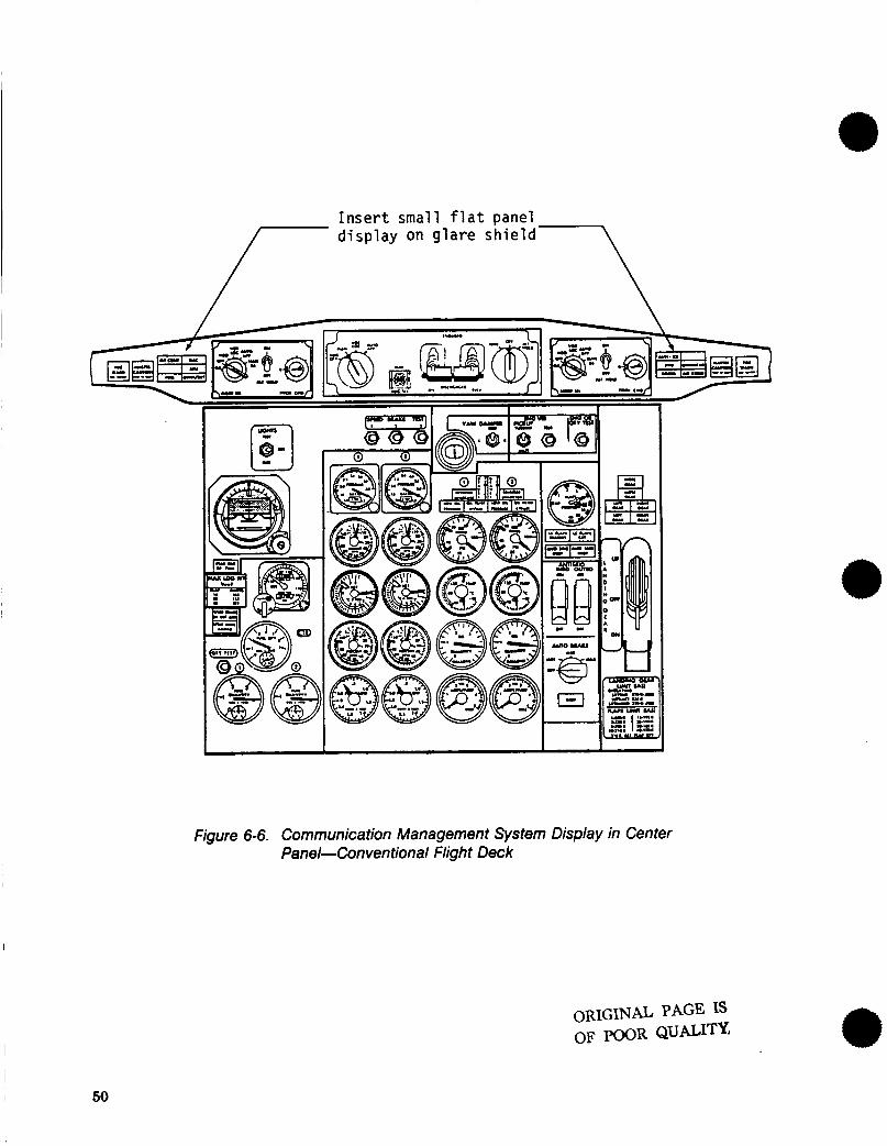
Insert small f l a t panel display on glare shield /-
Figure 6-6. Communication Management System Display in Center Panel-Conventional Flight Deck
50
6.1.3.1 Autopilot Interface
The advanced flight deck autopilot interfaced with the Mode-S data link system through the mode control panel on the glare shield. When an uplink containing an altitude constraint was displayed on the data link CDU, the cleared altitude was simultaneously displayed in the altitude window of the mode control panel. The altitude engage mode light turned blue to indicate the altitude had been preselected. The pilot could then fly to that altitude constraint by pressing the altitude engage mode switch, whose light would then change to orange or green indicating an armed or captured condition.
6.1.3.2 FMC Interface
The advanced flight deck Flight Management Computer (FMC) interfaced with the Mode-S data link system by automatically loading in an uplinked route. When an uplinked route was first received, the Electronic Flight Instrument (EFIS) Map display would indicate the new route as a dashed line. When an uplinked route was acknowledged by pressing WILCO on the data link CDU, the message TEMP F- PLN UPDATED appeared in the scratch pad line of the FMC CDU, indicating that the uplinked route was now resident in the temporary route buffer of the FMC. Executing the temporary flight plan via the FMC CDU then made the uplinked route part of the active flight plan and the dashed line on the Map display then became a solid line.
6.1.3.3 Information Management System
The information management system in the advanced flight deck functioned in the same manner as the communications management system in the conventional flight deck. A more generalized term was used to connote a broader application, that of managing all normal information in the flight deck, although no other specific uses were addressed in this study. Figure 6-7 illustrates the assumed location of the information management display.
6.2 TCAS
TCAS implementation consisted primarily of a traffic display for the TCAS traffic advisory, and the time critical warning for the TCAS resolution advisory. The traffic display was implemented differently in the conventional or advanced flight decks, while the time critical warning was the same for either type of flight deck.
6.2.1 TCAS Traffic Display
6.2.1.1 Conventional Flight Deck Implementation
The traffic display for the conventional flight deck was implemented on the weather radar indicator, which was installed on the forward center instrument panel, as shown in Figure 6-8. The weather radar indicator was further assumed to include a switching function to select the TCAS range value for display. For normal flight operations when there was no potential conflict, the weather radar display operated in the standard mode, based on the control settings on the weather radar control panel. It should be noted at this point that the potential use of TCAS for a general display of traffic (the CDTI concept) was not addressed by this study. Upon initiation of a TCAS traffic advisory, the weather radar display indicator was assumed to automatically switch to a new mode, defined as the TCAS traffic display mode, with the display origin at the center of the screen, utilizing whatever TCAS range scale was preselected on the weather radar indicator. No weather information was displayed in the TCAS traffic display mode, which remained selected until the weather mode was reselected by pressing the WEATHER MODE switch on the weather radar indicator.
51
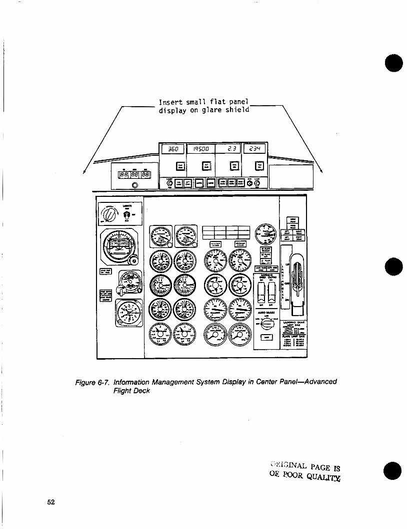
Figure 6- 7. Infomation Management System Display in Center Panel-Advanced Flight Deck
52
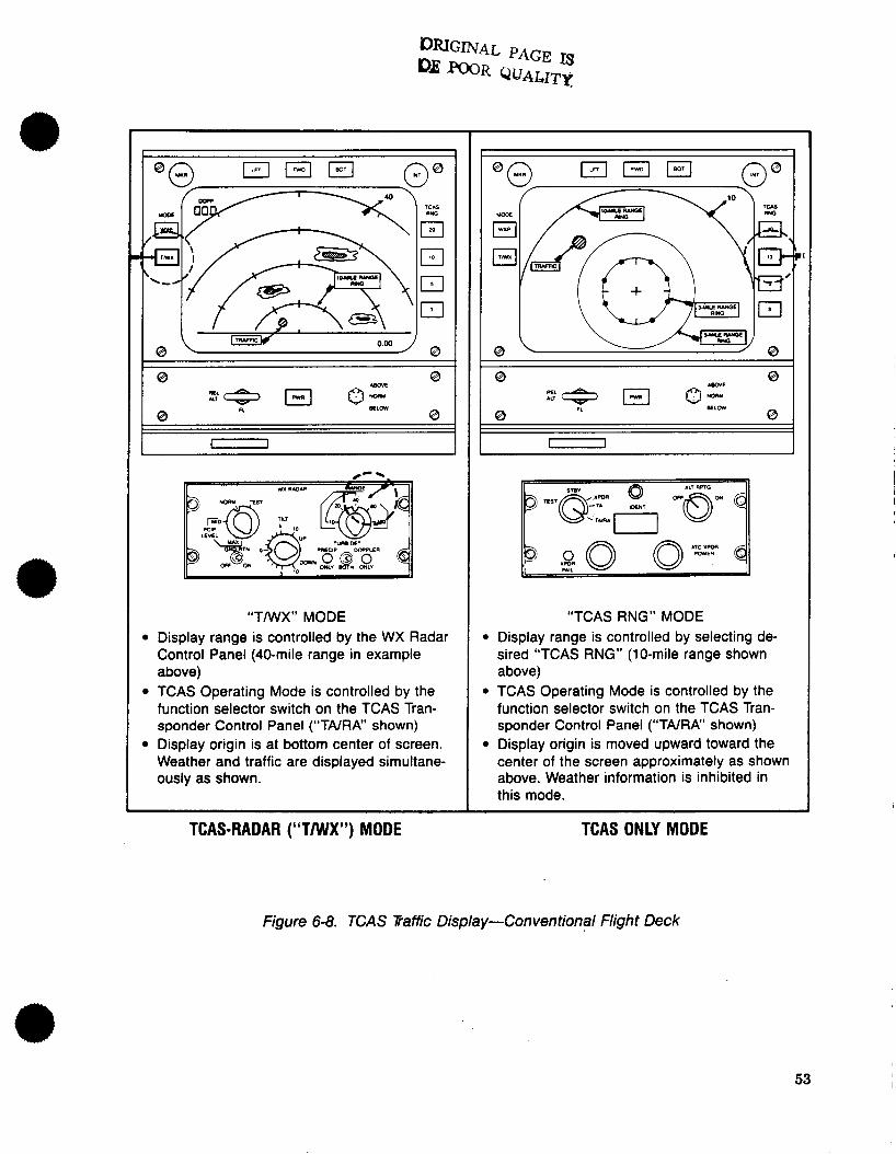
8
TCAS
El El m
&,
“TMIX ” MOD E Display range is controlled by the WX Radar Control Panel (40-mile range in example above) TCAS Operating Mode is controlled by the function selector switch on the TCAS Tran- sponder Control Panel (“TNRA” shown) Display origin is at bottom center of screen. Weather and traffic are displayed simultane- ously as shown.
TCAS-RADAR (‘‘TANX”) MODE
I
@ 8
“TCAS RNG” MODE 1 Display range is controlled by selecting de-
sired “TCAS RNG” (10-mile range shown above)
1 TCAS Operating Mode is controlled by the function selector switch on the TCAS Tran- sponder Control Panel (“TNRA” shown)
1 Display origin is moved upward toward the center of the screen approximately as shown above. Weather information is inhibited in this mode.
~~~~ ~~
TCAS ONLY MODE
Figure 6-8. TCAS Traffic Display-Conventional Flight Deck
53
6.2.1.2 Advanced Flight Deck Implementation
The TCAS traffic display was implemented in the advanced flight deck on the EHSI, as shown in Figure 6-9. For study purposes, the EHSI control panel was assumed to be modified to include a TCAS range selector, as shown. For normal flight operations with no potential conflicts, the EHSI operated in the standard mode, based on the EFIS control panel settings. Upon initiation of a TCAS traffic advisory, the display was assumed to automatically switch to the TCAS Traffic Display mode, utilizing whatever TCAS range scale was preselected on the EFIS control panel. No map or weather information was displayed in the TCAS mode, which remained until another mode was reselected from the EFIS control panel.
6.2.2 Time Critical Warning
Both conventional and advanced flight decks were assumed to comply with the provisions of Refer- ence 7, defining crew alerting requirements. There were four components comprising the time critical warning which were utilized in initiating and displaying the TCAS resolution advisory.
The first two components were the master aural and master visual warnings. The master aural warning was followed by the third component, which was a voice information display providing aural guidance for action and direction. The fourth component was the time critical warning display, which was implemented on the Instantaneous Vertical Speed Indicator (NSI), as shown in Figure 6-10, which was displayed simultaneously with the master warnings.
54
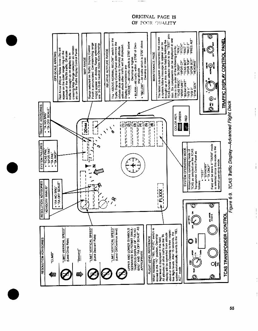
ORIGINAL PAGE IS OF P@OR qIJ4LITY
7- / /
t-Z
* . \
55

56
L
a a
n
a E o 0 W W
ORIGINAL PAGE IS 93 EooR QUALITY
7.0 RESULTS
This section presents and interprets the results of the timeline analysis of crew tasking based on the scenarios described in Section 5. For the reader wishing to obtain a more detailed description of the crew tasking results, Appendix C describes and illustrates the timeline histograms for each activity channel, organized by crew member and scenario. The data in Appendix C forms the basis from which the results of this section are developed.
It should be noted that the tasking results are stated in terms of percent tasking, which is defined (see sec. 4.2) as the fraction of maximum channel capacity required to accomplish a task. When tasking comparisons are made between alternative system concepts (e.g., between VHF voice and data link), the tasking increases and decreases are also given in terms of percent tasking, and are with respect to the baseline concept (i.e., VHF voice). The percent tasking values are additive or subtractive when used in this context. The percent tasking values described in Appendix C are averaged over the entire scenario.
As an example, Table 7-1 (a complete set of these tables is contained in Appendix C) lists channel tasking averaged over the entire normal ILS scenario for the copilot in the conventional flight deck. As shown, the internal vision tasking increases from 28.2% to 38.8% due to data link implementation. This yields a 10.6% tasking increase, averaged over the entire scenario. This apparently minor tasking increase becomes more significant when it is noted that the elapsed time for the entire normal ILS scenario was 1010 sec, while the cumulative time for all the communication related segments of the scenario was 178 sec (reduced by a factor of 5.67). The tasking increase averaged over the entire sce- nario can now be translated into a tasking increase averaged over the communication related segments, which is valid based on the fact that the tasking increase was due to implementation of a system (data link) which was utilized only during communication segments. Applying this technique to the above example, the 10.6% internal vision tasking increase averaged over the entire scenario translates to a 60% (5.67 times greater) tasking increase averaged over the communication related scenario segments. This type of transformation was utilized in developing the results presented in the remainder of this section of the report.
7.1 CREW TASKING EFFECTS DUE TO MODE-S DATA LINK
This section presents results correlated with the data link problem areas discussed in Section 4.1.
7.1.1 Input Techniques, System Control, and Clearance Acknowledgment
Data link input techniques, system control procedures, and clearance acknowledgment are shown to impact only copilot tasking, based on the assumptions made for system implementation. Table 7-2 indicates copilot tasking during a normal ILS approach. The data link CDU, placed in the center aisle stand, requires approximately 20% left hand tasking increase during communication periods for the copilot. This level of left hand tasking appears to be acceptable, especially considering the corresponding 27% right hand tasking decrease due to not having to key the microphone for transmitting. However, the internal vision tasking is quite significantly increased due to the CDU concept of input/output. and system control. Table 7-2 indicates 60% internal vision tasking increase during communication seg- ments. The majority of this increase is due to reading the uplinked message on the CDU. The minimal pilot tasking impact is shown in Table 7-3.
7.1.2 Negotiating a New ATC Clearance
In the conventional flight deck, there is an insignificant impact on pilot tasking due to negotiating a new clearance. In the advanced flight deck, however, pilot tasking is increased in both internal vision and cognitive channels, while preserving the large left hand savings made possible by autopilot elimina-
57
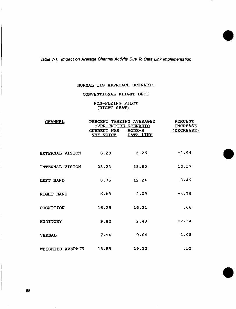
Table 7-1. Impact on Average Channel Activity Due To Data Link Implementation
NORMAL ILS APPROACH SCENARIO
CONVENTIONAL FLIGHT DECK
NON-FLYING PILOT (RIGHT SEAT)
CHANNEL
EXTERNAL VISION
INTERNAL VISION
LEFT HAND
RIGHT HAND
COGNITION
AUDITORY
VERBAL
WEIGHTED AVERAGE
PERCENT TASKING AVERAGED PERCENT
CURRENT NAS MODE-S (DECREASE) OVER ENTIRE SCENARIO INCREASE
VHF VOICE DATA LINK
8.20 6.26
28.23 38.80
8.75 12.24
6.88 2.09
16.25 16.31
9.82 2.48
7.96 9.04
18 . 59 19 . 12
-1.94
10.57
3.49
-4.79
.06
-7.34
1.08
.53
I 58
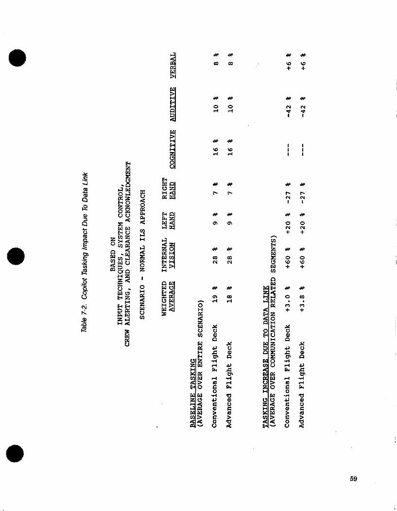
* d e d e
c o c o * * u ) u ) + +
* d e
0 0 d r (
I I I 1 I I
* d e
b b
d e *
b b ( v ( v I I
ts d e d e
m m d e d e
0 0 ( Y N + +
h
Q,
a" c 0
- 3 H
a d e d e
c o c o C U N
d e d e
U W \ O w + + m
B o o
I
d e d e
m c o n d d U W
5 2 R Q d
8 %
59
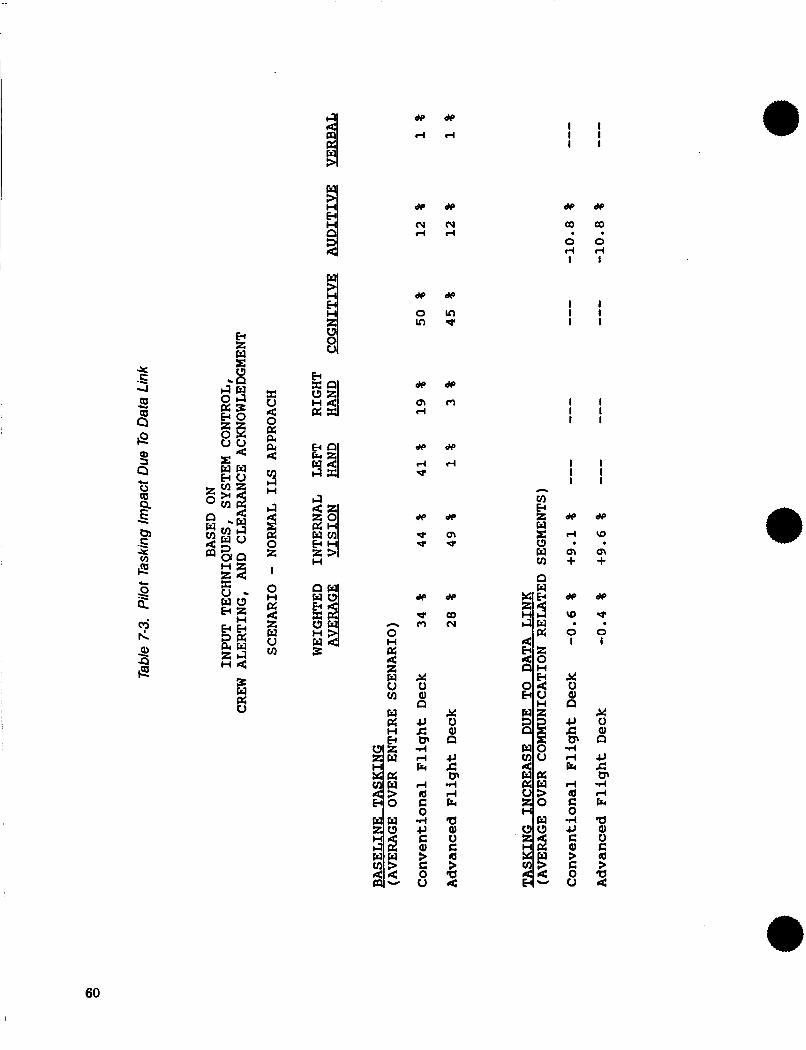
X -E 4
c g
I
W p:
d p d p
d d
d p d p
N ( Y d d
d p d p
o m d
W d P
d d *
de
* rl
X u al
c, c F 4 d E
r( a c 0 d c, c Q)
n
dp
a (Y
X u al
c, c F 4 rl E
5 01 u c
a 4
n
s
I t I I I 1
d e *
a a 0 0 r ( r (
I 1
. .
I 1 I 1 I 1
I 1 I I I I
I I I I I I
60
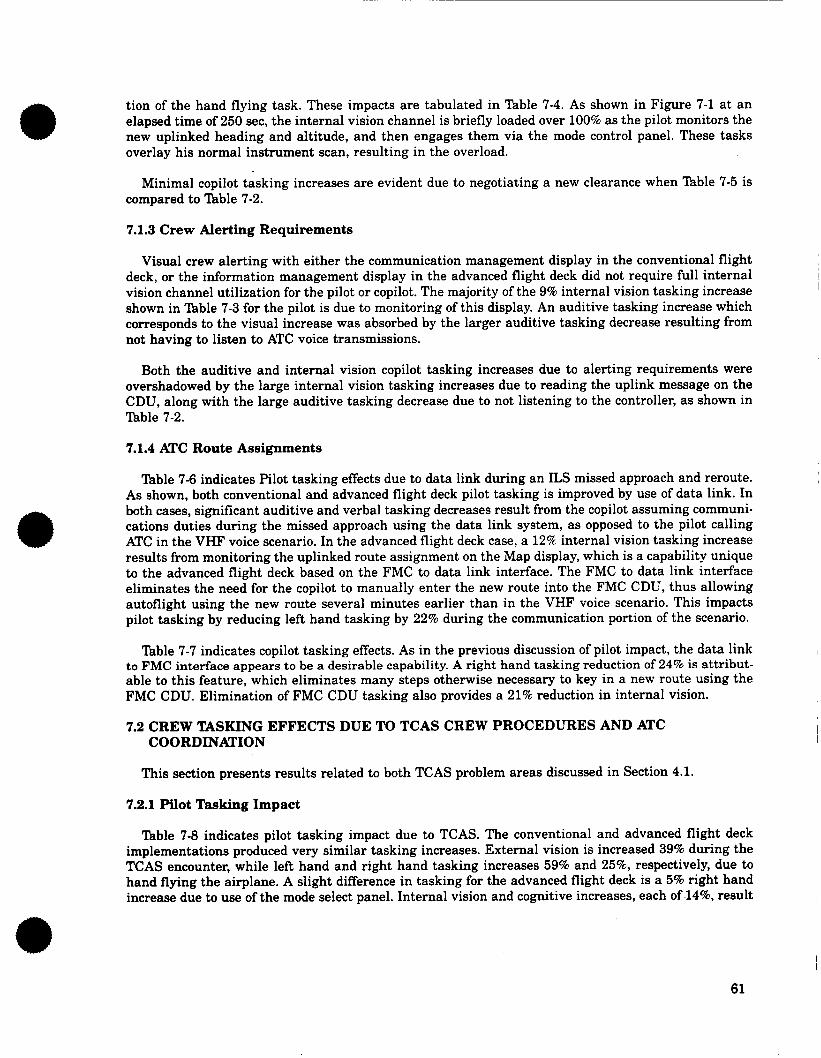
tion of the hand flying task. These impacts are tabulated in Table 7-4. As shown in Figure 7-1 at an elapsed time of 250 sec, the internal vision channel is briefly loaded over 100% as the pilot monitors the new uplinked heading and altitude, and then engages them via the mode control panel. These tasks overlay his normal instrument scan, resulting in the overload.
Minimal copilot tasking increases are evident due to negotiating a new clearance when Table 7-5 is compared to Table 7-2.
7.1.3 Crew Alerting Requirements
Visual crew alerting with either the communication management display in the conventional flight deck, or the information management display in the advanced flight deck did not require full internal vision channel utilization for the pilot or copilot. The majority of the 9% internal vision tasking increase shown in "able 7-3 for the pilot is due to monitoring of this display. An auditive tasking increase which corresponds to the visual increase was absorbed by the larger auditive tasking decrease resulting from not having to listen to ATC voice transmissions.
Both the auditive and internal vision copilot tasking increases due to alerting requirements were overshadowed by the large internal vision tasking increases due to reading the uplink message on the CDU, along with the large auditive tasking decrease due to not listening to the controller, as shown in lhble 7-2.
7.1.4 ATC Route Assignments
Table 7-6 indicates Pilot tasking effects due to data link during an ILS missed approach and reroute. As shown, both conventional and advanced flight deck pilot tasking is improved by use of data link. In both cases, significant auditive and verbal tasking decreases result from the copilot assuming communi- cations duties during the missed approach using the data link system, as opposed to the pilot calling ATC in the VHF voice scenario. In the advanced flight deck case, a 12% internal vision tasking increase results from monitoring the uplinked route assignment on the Map display, which is a capability unique to the advanced flight deck based on the FMC to data link interface. The FMC to data link interface eliminates the need for the copilot to manually enter the new route into the FMC CDU, thus allowing autoflight using the new route several minutes earlier than in the VHF voice scenario. This impacts pilot tasking by reducing left hand tasking by 22% during the communication portion of the scenario.
'lhble 7-7 indicates copilot tasking effects. As in the previous discussion of pilot impact, the data link to FMC interface appears to be a desirable capability. A right hand tasking reduction of 24% is attribut- able to this feature, which eliminates many steps otherwise necessary to key in a new route using the FMC CDU. Elimination of FMC CDU tasking also provides a 21% reduction in internal vision.
7.2 CREW TASKING EFFECTS DUE TO TCAS CREW PROCEDURES AND ATC COORDINATION
This section presents results related to both TCAS problem areas discussed in Section 4.1.
7.2.1 Pilot Tasking Impact
Table 7-8 indicates pilot tasking impact due to TCAS. The conventional and advanced flight deck implementations produced very similar tasking increases. External vision is increased 39% during the TCAS encounter, while left hand and right hand tasking increases 59% and 25% respectively, due to hand flying the airplane. A slight difference in tasking for the advanced flight deck is a 5% right hand increase due to use of the mode select panel. Internal vision and cognitive increases, each of .14%, result
61
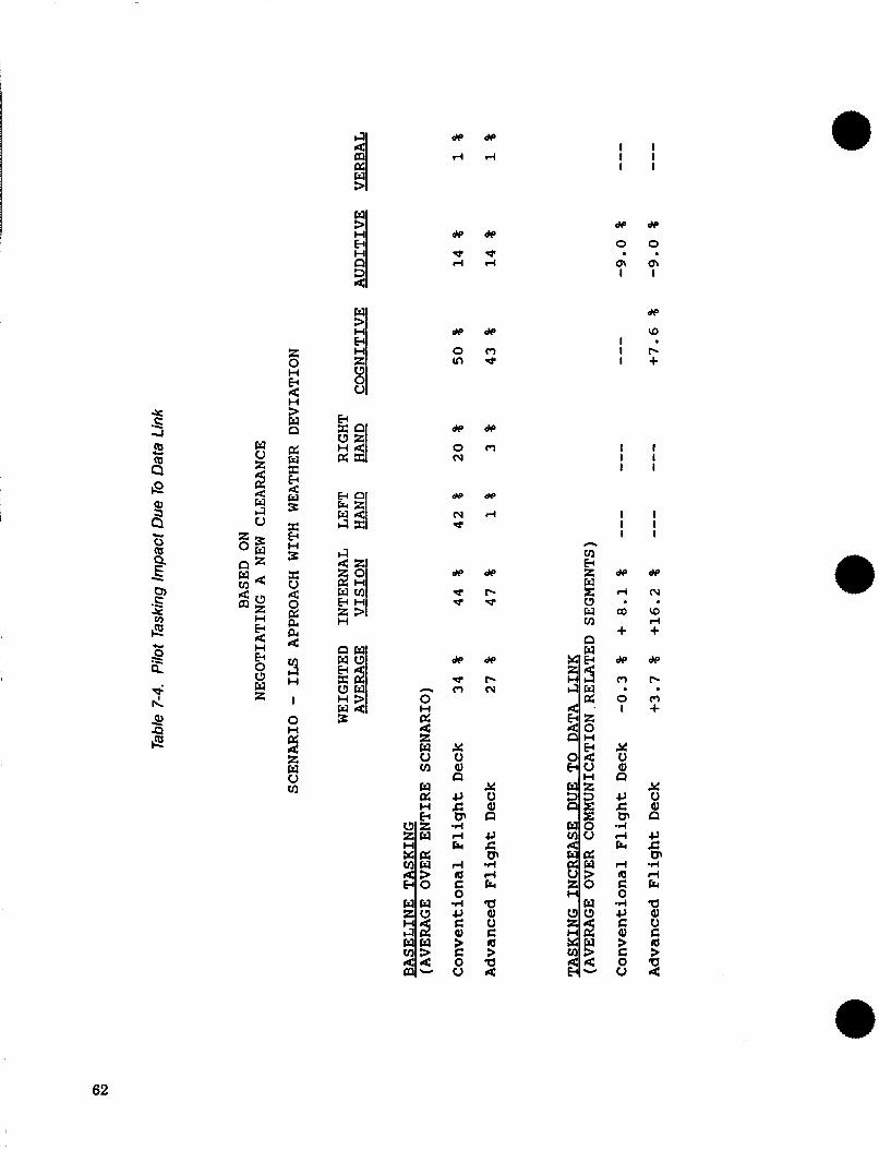
* C --.
c g d F:
H
d e *
d d
d p d p
o m m e
* d e
o m hl
d e w
h l d d
1 1 I 1 I 1
d e d e
0 0
dp
a I . I f - I +
I 1 I 1 1 1
I 1 I 1 I I
h
62
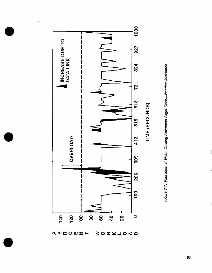
I I I 0 I-
W I 3 I a I
I
I
a a I
W Y v )Z si I
Ok I Z n I 4 I
I I I I I I I I I
cv d
- l -
Q) - 0
c*)
I
I 1 I 1 - 5 1 I
0 0 0 0 0 0 0 0 d c v 0 0 0 ( D d c u F F l -
I 8 Q
63
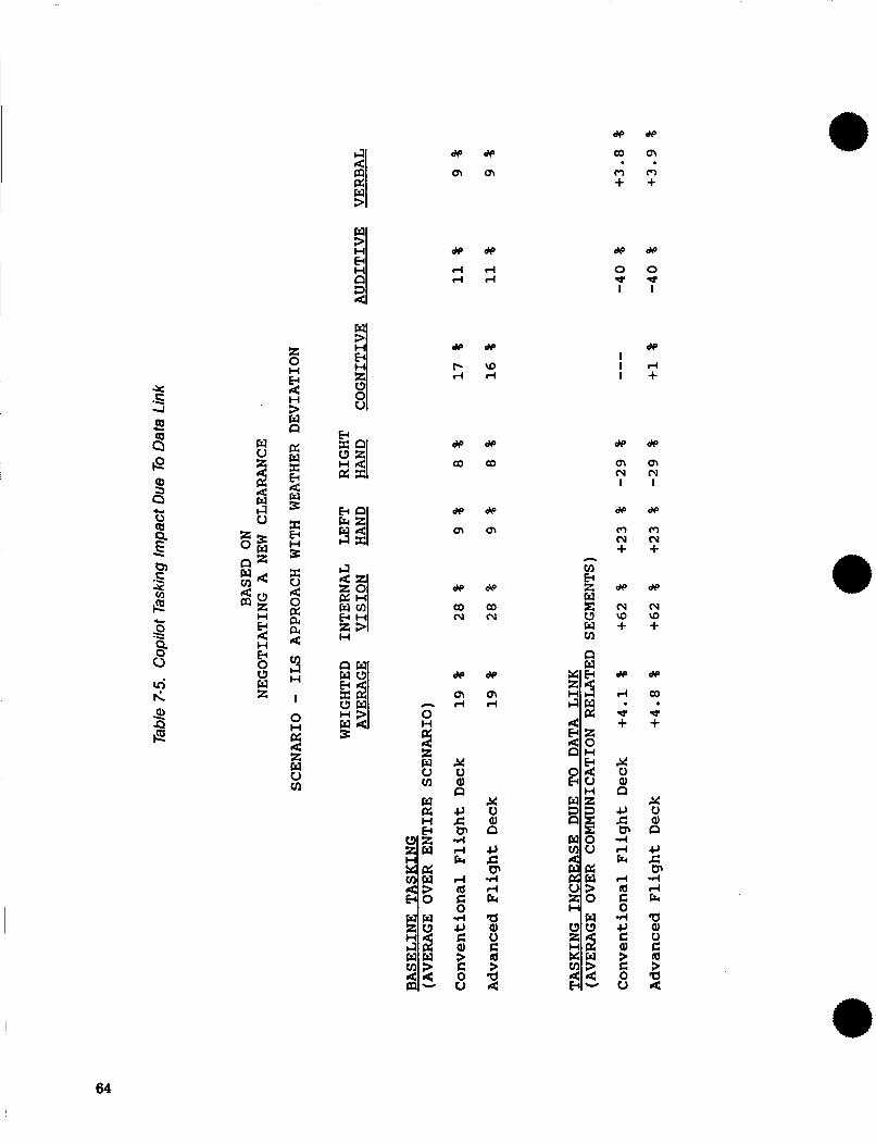
d e w
a m m m + + . .
.E 4
c 0 z E -
H
n &
m
d e d e
d r l d r l
d e d e
b W r l d
d e d e
o m h d r l 0
d e &
o m
d w : a
d e d e
0 0 * e I I
de I I d I +
m m c u m I I
64
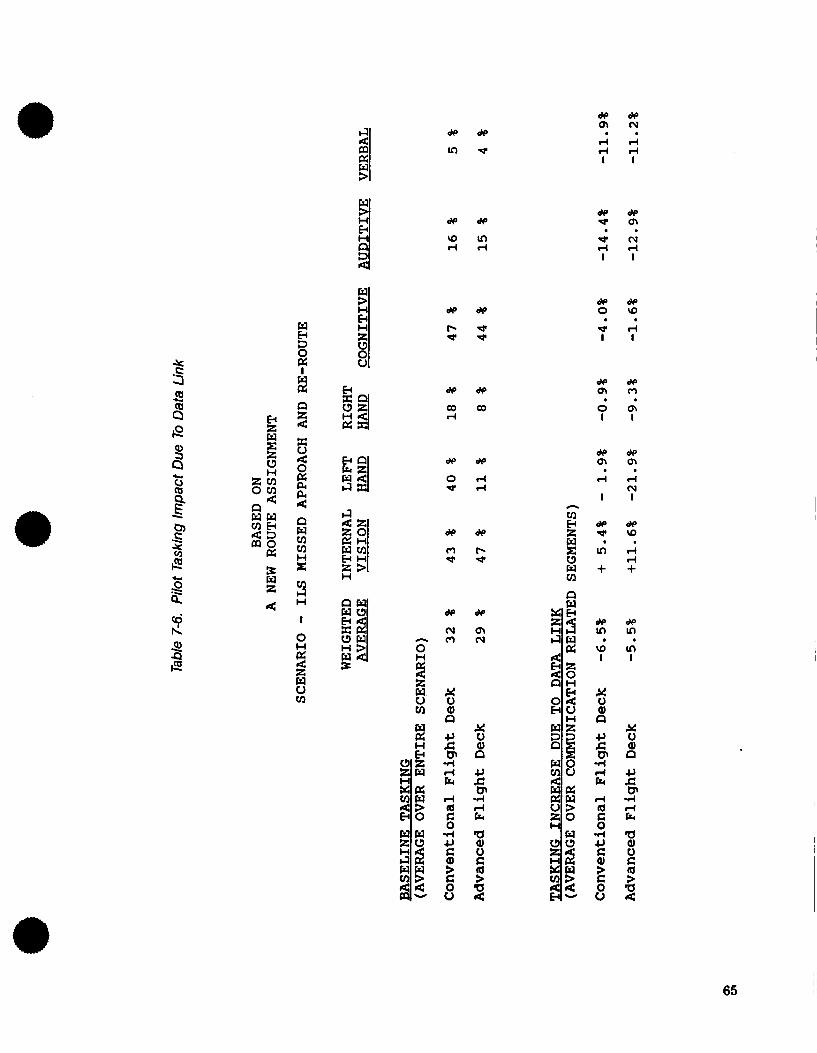
X .E
c g cd F: s d Q
w f3 1 2
8 z 4 0
PI 4
w v1 VI H x
n
3 H
I
0 H
z w W VI
!%
d e w
m w
d e d e
\ D m d d
de
e e
de
co
de
r-l d
de
c- e
w m (v
K 0 a,
JJ c P 4 4 Fr
5 a, 0 E
a 4
n
9
d e d e Q I N
d d . . d d I I
w w m m . . 0 0 I I
d e d e m m d d
cv I I
65
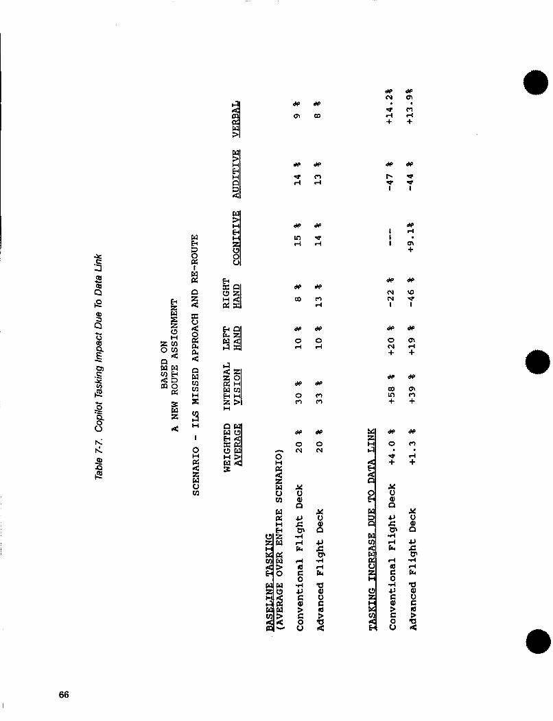
d e d e l u m * m 4 d + + . . d p d e
m a
de
* * I
dp d
m +
de
rD w I
dp
m rl + dp
m m +
de
m d +
x 0 a,
JJ c F 4 rl E
a al u E:
a 4
n
s
d e d e
e m r l d
de
I- * I
I I I
dp
lu cu I
de
0 cu + de
a ln +
de
0
e i
% al
JJ c 0 4 rl E d Q E: 0
n
w p:
k
X u 2 E P4 4
d e d e
0 0 4 r l
c 0
- b,
X v)
.E
d * d e
o m m m 3w z
c p 3 0
H
3 H
1
P
c 3 w H 3 W 4 3
d p d e
0 0 n l u l u 2
p: 4 2 W u v1
P d Q
ii -$ v1 w
wlm -;i a
66
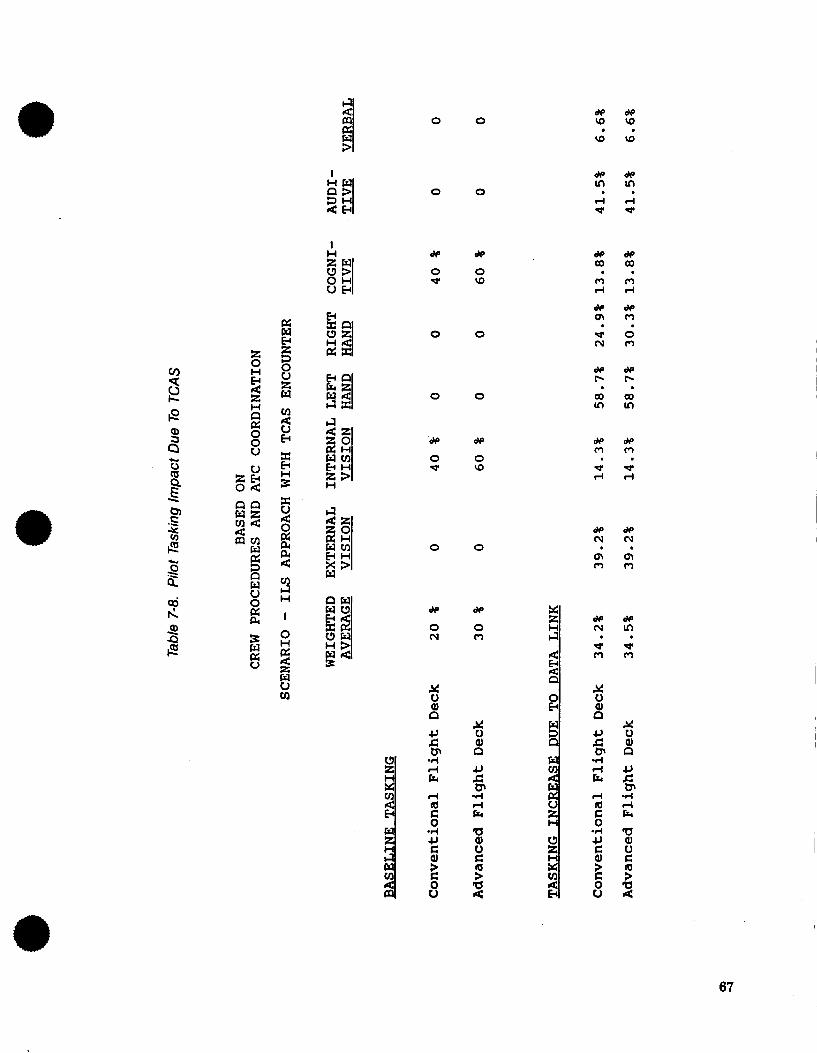
c 0 2
P E Q
u Z B 0 4 nn w z m 4 S m
2
E w u 0
X
3 E
3 H
I
0 0
I q 4 B
0 0
I de de
0 0 w \o
0 0
ii cn
0 0
# #
0 0 w \o
0 0
# #
0 0 cv m
4J
-4 d R
d 4 c 0
.I4
4 c al
0 0 2
% al P 4J c OI d d E
a al u c
a 4 s
# d e W W \ o w . .
# d e c o c o m o d d
* * a m - 0 c v o
. .
. . # # P P
c o c o m m . .
# #
la . . gI cv m
67
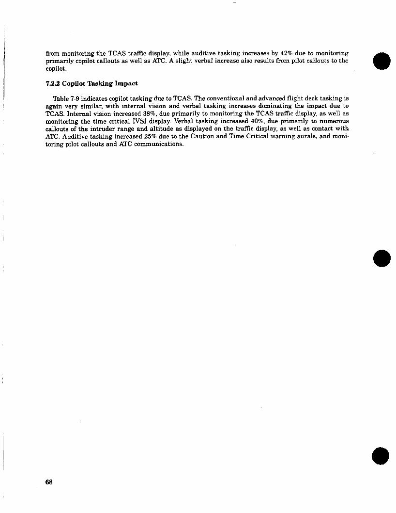
from monitoring the TCAS traffic display, while auditive tasking increases by 42% due to monitoring primarily copilot callouts as well as ATC. A slight verbal increase also results from pilot callouts to the copilot.
7.2.2 Copilot Tasking Impact
lhble 7-9 indicates copilot tasking due to TCAS. The conventional and advanced flight deck tasking is again very similar, with internal vision and verbal tasking increases dominating the impact due to TCAS. Internal vision increased 38%, due primarily to monitoring the TCAS traffic display, as well as monitoring the time critical IVSI display. Verbal tasking increased 40%, due primarily to numerous callouts of the intruder range and altitude as displayed on the traffic display, as well as contact with ATC. Auditive tasking increased 25% due to the Caution and Time Critical warning aurals, and moni- toring pilot callouts and ATC communications.
68
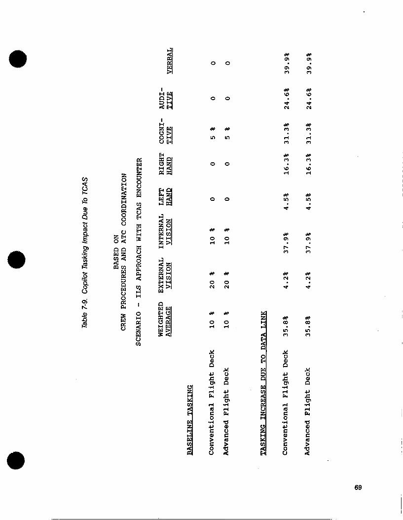
de de m m m m 0 m
0 0
I de de rg v)
d (v cu
0 0
d e d e
I n I n
de dp m m rl 4 m m
de de m m
v) rg rl rl
0 0
de de In In
d -r 0 0
c 0
\ P X i3 2
d e d e
0 0 d r l
de de m m Iz Iz m m
0 zi3 0 4
3: 0
H
c 0 2
3 0
d e d e
0 0 ( v ( v
de de (v (v
d e 3 H
I
0 H
z w u tn
2 d e d e
0 0 r l r l
P d Q
I d $1 Er
.
69
8.0 CONCLUSIONS AND RECOMMENDATIONS
8.1 IMPLICATIONS FOR FLIGHT DECK IMPLEMENTATION
Several recommendations for flight deck implementation of Mode-S data link and TCAS are sug- gested by the results of this study.
8.1.1 Mode-S Data Link
The results of this study indicate that the selected implementation of Mode-S data link (based on a CDU concept) in conventional and advanced flight decks may be acceptable during periods of low crew activity level, such as in the cruise phase of flight. The substantial visual tasking increases resulting from a CDU implementation of data link could create vision channel overloads during high workload phases of flight. It should be noted that crew incapacitation could also cause a high workload condition in which additional visual tasking from a CDU implementation of data link could create vision channel overloads. It is recommended that consideration be given to alternative means of data link crew inter- face to offload the vision channels, including investigation of speech technology.
Specific recommendations are also suggested in the following areas.
1. CDU codiguration-The extent to which some success was indicated by this study in a CDU implementation of data link may be in part due to the structured menu design employed. Minimiz- ing processing and page selection time will be a significant factor in the design of a successful data link system using a CDU. Another important factor may be having a large display surface capable of displaying an entire message at once, without ambiguous abbreviations, as was illustrated in this study.
2. Graphic display of clearances-A data link interface with the EFIS in an advanced flight deck could potentially minimize crew tasking increases for certain types of uplinks or downlinks. Com- ponents to consider are the Map/Nav display, primary flight display, and the vertical situation display which is being studied by Boeing. Data that could be displayed include altitudes, headings, and lateral routes. Alternate display means would still be required for other types of data.
3. Autopilot interface-Some means of data link interface with the autopilot may be desirable, how- ever, goals of enhancing pilot situational awareness and effectiveness as a system manager may have to be traded against the goals of minimizing crew tasking.
4. Crew Alerting-An area for further research could be whether pilot internal vision monitoring of the communication or information management displays is required in all cases. Normal mes- sages, annunciated aurally, may not require further attention from the pilot, limiting tasking increases due to data link.
8.1.2 TCAS
Conventional and advanced flight decks are both significantly affected by TCAS implementation. The crew tasking required during a traffic advisory and subsequent resolution advisory leaves little time available for coordination with ATC using conventional VHF voice techniques.
TCAS implementation techniques to minimize crew tasking should be considered, such as automati- cally switching the weather radar/EHSI display to the TCAS traffic display. The usefulness of the TCAS range control should also be considered. If no CDTI function is provided, the TCAS range could possibly
be automated or fixed to one setting. The possibilities of displaying weather or route data on a TCAS traffic display should also be considered. Use of a vertical situation display for TCAS traffic information is another possibility.
8.2 IMPLICATIONS FOR NAS UPGRADE PLANS
NAS planning for TCAS should consider the significant crew tasking increases that have been shown to result from a TCAS encounter, keeping in mind the high nuisance alarm rate demonstrated to date by TCAS inflight testing. The high tasking increases, when combined with the high nuisance alarm rate, may result in significant crew reluctance to follow TCAS commands during a resolution advisory. Con- sideration should be given to reducing the crew tasking (possibly by modifying or eliminating the traffic display) or reducing the nuisance alarm rate prior to widespread introduction of TCAS in the NAS.
8.3 INTEGRATION OF FUTURE AIRBORNE AND ATC OPERATIONS
Consideration should be given to interfacing the TCAS system with the ATC system via Mode-S data link, allowing automatic transmission of coordination messages to ATC prior to R. A. maneuvering. Some means of display should be included to inform the crew that ATC is aware of the TCAS detected conflict. If ATC has additional knowledge (particularly of intent) such as the intruder’s assigned altitude that would negate the conflict, then display of such a situation could also be presented to the crew.
72
9.0 REFERENCES
1. “National Airspace System Plan; Facilities, Equipment, and Associated Development,” GPO: 1987 0-179-550, Federal Aviation Administration, April 1987.
2. “Cockpit Data Management Requirements (Current Technology Aircraft),” DOT/FAMPM-83/25, ARINC Research Corp., T. P. Berry, October 1983.
3. “1990’s ATC Environment for Aircarrier Aircraft,” Boeing Document D6-53010, R. L. Erwin and J. H. Foster, July 1985.
4. “Current Workload Methods for Emerging Challenges,” Boeing Document D644563TN, D. L. Parks, July 1977.
5. “Timeline Analysis Program (TLA) Users Guide,” Boeing Document D6-44646, A. F. Anderson and K. H. Miller, December 1977.
6. “Timeline Analysis Program (TLA-1) Final Report- Appendices,” Boeing Document D6-42377-6, NASA CR-144943, K. H. Miller, April 1976.
73
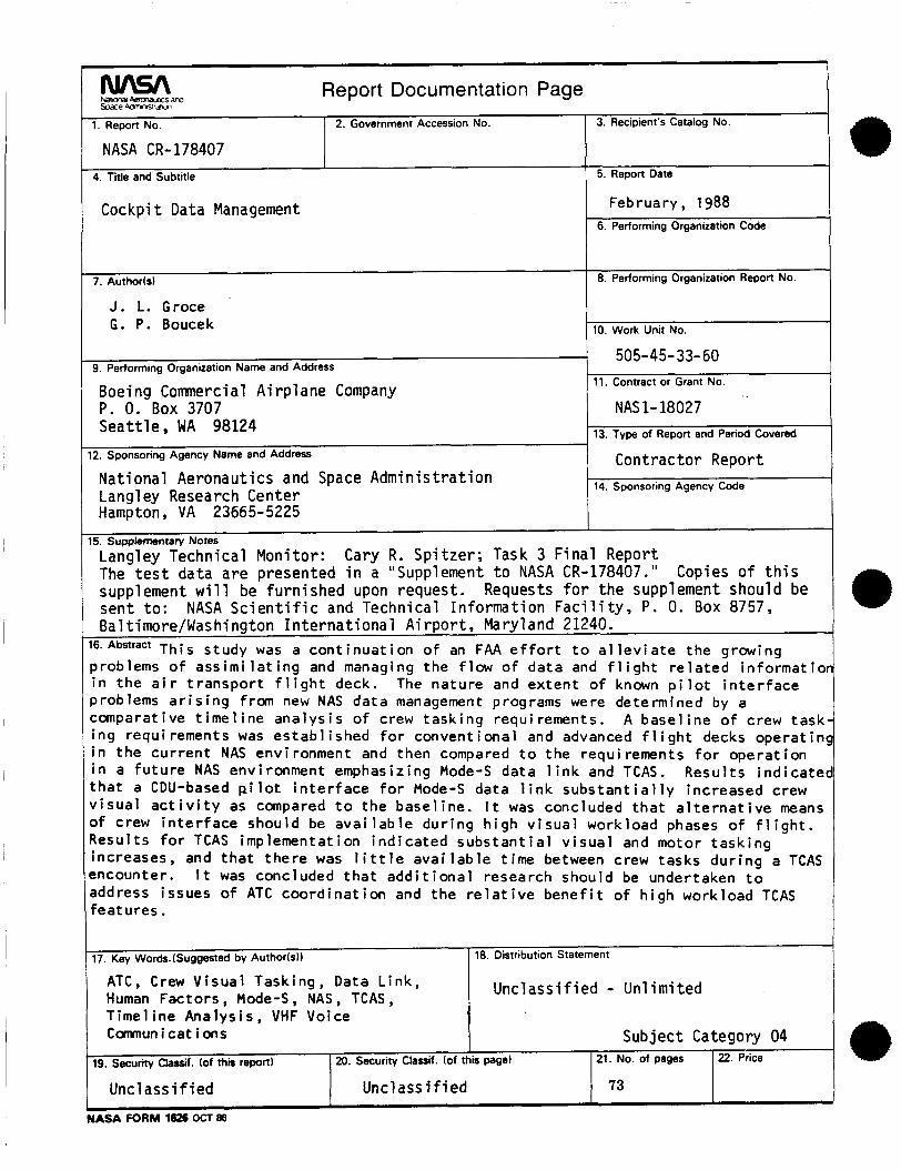
cw\sA Nam km-&ics and Report Documentation Page I %ace Mr-wraicr
1. Report No. 2. Government Accession No. 3. Recipient's Catalog No.
NASA CR- 178407 5. Report Date 4. Title and Subtitle
7. Author(s1
Cockpit Data Management
8. Performing Organization Report No.
February, 1988
- 9. Performing Organization Name and Address
Boeing Commercial Airplane Company
Seattle, WA 98124 P . 0. Box 3707
12. Sponsoring Agency Name and Address
I
505-45-33-60 11. Contract or Grant No.
NAS 1- 18027 13. Type of Report and Period Covered
Contractor ReDort
17. Key Words.(Suggested by Authorkll
J. 1. Groce G. P. Boucek
18. Distribution Statement
d 10. Work Unit No.
Time1 ine Analysis, VHF Voice Communications Subject Category 04
National Aeronautics and Space Administration Lanql e.y Research Center
21. No. of pages 19. security chrsif. (of thin report1 20. Security Classif. (of this page1
Unclassified Uncl ass i f i ed 73
14. Sponsoring Agency Code
22. Price
- - Hampton, VA 23665-5225
Langley Technical Monitor: Cary R. Spitzer; Task 3 Final Report The test data are presented in a "Supplement to NASA CR-178407." supplement will be furnished upon request. sent to: NASA Scientific and Technical Information Facility, P. 0. Box 8757, Bal timore/Washington International Airport, Maryland 21240.
16.Abstract This study was a cont inuat ion o f an FAA e f f o r t t o a l l e v i a t e the growing problems o f ass im i la t i ng and managing the f l o w o f data and f l i g h t re la ted in format io i i n the a i r t ranspor t f l i g h t deck. problems a r i s i n g from new NAS data management programs were determined by a comparative t i m e l i n e analys is o f crew task ing requirements. A base l ine o f crew task ing requirements was es tab l i shed f o r conventional and advanced f l i g h t decks operatinc i n the cur ren t NAS environment and then compared t o the requi rements f o r operat ion i n a f u t u r e NAS environment emphasizing Mode-S data l i n k and TCAS. Resul ts indicatec t h a t a CDU-based p i l o t i n te r face f o r Mode-S data l i n k s u b s t a n t i a l l y increased crew v i sua l a c t i v i t y as compared t o the basel ine. I t was concluded t h a t a l t e r n a t i v e means of crew i n t e r f a c e should be ava i l ab le dur ing h igh v i sua l workload phases o f f l i g h t . Resul ts f o r TCAS implementation ind ica ted subs tan t i a l v i sua l and motor task ing increases, and t h a t there was l i t t l e ava i l ab le t ime between crew tasks dur ing a TCAS encounter. I t was concluded tha t add i t i ona l research should be undertaken t o address issues of ATC coord ina t ion and the r e l a t i v e bene f i t o f h igh workload TCAS features.
15. Supplementary Notes
Copies of this Requests for the supplement should be
The nature and extent o f known p i l o t i n t e r f a c e
1 Unclassified - Unlimited ATC, Crew Visual Tasking, Data L ink, Human Factors, Mode-S, NAS, TCAS,