Embed Size (px)
Citation preview

This document contains information which is confidential and/or proprietary to Knowles Electronics, LLC or its affiliates. Do not distribute or use the information contained herein without permission from an authorized representative of Knowles
Page 1 of 20
©2012 Knowles Electronics
2403 260 00098
SPEAKER-1115-4-SC-COBRA SF The 11×15×4 mm COBRA SF is high-end minia-ture speaker of rectangular shape with lateral sound outlets. Specifically designed for side-firing applications, this speaker version enables a reduced application height in small, slim con-sumer devices, such as music phones, smartphones or tablet computers where high quality sound and maximum space efficiency are required. In addition, COBRA SF features Knowles’ ad-vanced membrane technologies resulting in a state-of-the-art silicone membrane. This unique silicone membrane enables ultra-high excursion rates and superior robustness.
Features:
• Lateral sound outlet integrated in cover of speaker
• Significant height reduction for side-firing applications
• 100% in-line measurement of all specified acoustical and electrical parameters
• Pre-tested and integrated side-porting acoustics
• Manufactured to the highest standards
• High power handling capacity of 1000mW

Page 2 of 20
©2011 Knowles Electronics Release – Revision: A
2403 260 00098
Contents 1. Theory of operation............................................................................................................................. 3
2. Mechanical Layout and Dimensions .................................................................................................... 4 2.1. Main dimensions ......................................................................................................................... 4 2.2. PWB layout & electric polarity .................................................................................................... 5 2.3. Magnetic polarity ........................................................................................................................ 5 2.4. Spring force ................................................................................................................................. 6 2.5. Part marking/labeling .................................................................................................................. 7 2.6. Material list .................................................................................................................................. 8 2.7. Force on component ................................................................................................................... 9
3. Electrical and Acoustical Specifications ............................................................................................. 10 3.1. Frequency response .................................................................................................................. 10 3.2. Electro-acoustic parameters ..................................................................................................... 11 3.3. Power handling .......................................................................................................................... 11 3.4. Measured parameters ............................................................................................................... 12 3.5. Measurement setup .................................................................................................................. 12 3.6. Measurement adapter .............................................................................................................. 13
4. Environmental Conditions ................................................................................................................. 14 4.1. Storage....................................................................................................................................... 14 4.2. Transportation ........................................................................................................................... 14 4.3. Functionality .............................................................................................................................. 14
5. Environmental Tests .......................................................................................................................... 15 5.1. Qualification tests...................................................................................................................... 15 5.2. Reliability tests .......................................................................................................................... 15 5.3. Sample size, sequence ............................................................................................................... 15 5.4. Period of shelf-life ..................................................................................................................... 15 5.5. Testing procedures .................................................................................................................... 15
6. Related Documents ........................................................................................................................... 19
7. Change History .................................................................................................................................. 20
8. Disclaimer .......................................................................................................................................... 20

Page 3 of 20
©2011 Knowles Electronics Release – Revision: A
2403 260 00098
1. Theory of operation
SPEAKER-1115-4-SC-COBRA SF is an electrodynamic transducer, designed to translate electrical analog signals into acoustic waves. The input signal is fed into a coil which is exposed to a permanent magnet-ic field and where a membrane is attached to. Through the principle of the resulting electromagnetic force, the membrane is moved according to the contents of the input signal and thus emitting sound by the air shifted.

Page 4 of 20
©2011 Knowles Electronics Release – Revision: A
2403 260 00098
2. Mechanical Layout and Dimensions
2.1. Main dimensions

Page 5 of 20
©2011 Knowles Electronics Release – Revision: A
2403 260 00098
2.2. PWB layout & electric polarity
2.3. Magnetic polarity

Page 6 of 20
©2011 Knowles Electronics Release – Revision: A
2403 260 00098
2.4. Spring force
SPRING FORCE TABLE Force at Basket level 0.0 mm min. 0.6 N
Force at Start Working position 0.5 mm min. 0.3 N uncompressed (delivery position) 0.65 ±0.15mm 0.0 N
Force at PPP level -0.2 mm max 1.2 N

Page 7 of 20
©2011 Knowles Electronics Release – Revision: A
2403 260 00098
2.5. Part marking/labeling The samples have a serial number on bottom (pot) side

Page 8 of 20
©2011 Knowles Electronics Release – Revision: A
2403 260 00098
2.6. Material list
Material of basket: Polycarbonate
Material of membrane: Silicone
Material of membrane frame Polybutylene Terephthalate (PBT)
Material of pot: soft magnetic Iron
Material of magnet: Nd Fe B
Material of contact CrNi-Steel, gold plated
Material of cover: Polycarbonate
Dimensions (in mm): 11 × 15 × 4
Mass: 1.56 g

Page 9 of 20
©2011 Knowles Electronics Release – Revision: A
2403 260 00098
2.7. Force on component
FORCES ON DIFFERENT STATE OF COMPONENT STATE MIN. SURFACE OF
PRESSURE [mm²] MAX. PERMANENT
FORCE [N] MAX. HANDLING
FORCE [N] FROM FRONT TO BACK (GASKET AREA)
- 10 15
FROM SIDE 1 TO SIDE 3 3 10 15 FROM SIDE 2 TO SIDE 4 10 10 15 TO POT - 10 15 TO MEMBRANE - 0 0 PULL OFF FORCE - 0 20
Page 10 of 20
©2011 Knowles Electronics Release – Revision: A
2403 260 00098
3. Electrical and Acoustical Specifications
3.1. Frequency response
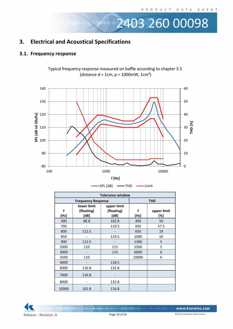
Typical frequency response measured on baffle according to chapter 3.5
(distance d = 1cm, p = 1000mW, 1cm³)
Tolerance window Frequency Response THD
f [Hz]
lower limit (floating)
[dB]
upper limit (floating)
[dB] f
[Hz] upper limit
[%] 300 88.8 102.8 300 50 700 - 119.5 450 37.5 800 112.5 - 650 19 850 - 119.5 1000 10 900 112.5 - 1300 5
2000 110 115 5500 5 3000 - 115 6000 6 3500 110 - 10000 6 4000 - 118.5 6000 116.8 132.8
7000 116.8 - 8000 - 132.8
10000 102.8 116.8
0
10
20
30
40
50
60
80
90
100
110
120
130
140
100 1000 10000
THD
[%]
SPL
[dB
rel 2
0uPa
]
f [Hz]
SPL [dB] THD Limit

Page 11 of 20
©2011 Knowles Electronics Release – Revision: A
2403 260 00098
3.2. Electro-acoustic parameters
Loudspeaker mounted in adapter acc. to 3.5. 1. Rated impedance Z: 6Ω 2. Voice coil DC resistance R: 5.4Ω±10% 3. Resonance frequency (measured @1cm³, 1000mW) f0: 780Hz±10% 4. Maximum usable excursion (peak-to-peak) xmax: 0.74mmp-p 5. Nominal characteristic sensitivity 73.5±2.5dB (measured at 1W in 1cm, calculated to 1m average from 2kHz to 3kHz, thermal compression included) 5.1 Measured characteristic sensitivity (at 1W in 10cm) 86.5±2dB average from 2kHz to 3kHz 6. THD according chapter 3.1 7. Rub & buzz no audible Rub & Buzz
All acoustic measurements at 23±2°C
3.3. Power handling Speaker mounted in 1cm³ test device (open front) 1. Max sine Power 1000mW (RMS) 2. Max short term power (70°C, 1 sec. ON / 60sec. OFF) 1200mW (RMS) (pink noise, 2nd order high pass filtered, -3dB at 1.2kHz, crest factor 2) 3. Max continuous power (70°C, 500h) 1000mW (RMS) (pink noise, 2nd order high pass filtered, -3dB at 800Hz, crest factor 2)

Page 12 of 20
©2011 Knowles Electronics Release – Revision: A
2403 260 00098
3.4. Measured parameters
3.4.1. Sensitivity
SPL is expressed in dB rel 20µPa, computed according to IEC 268-5. Measurement set up and parameters according chapter 3.5. This test is performed for 100% of products in the production line.
3.4.2. Frequency response
Frequency response is measured according test set up in chapter 3.3 data sheet and checked against the tolerance window defined in chapter 3.5. This Test is performed for 100% of products in the pro-duction line.
3.4.3. Total harmonic distortion (THD)
Is measured according IEEE and test set up in chapter 3.5. This test is performed for 100% of products in the production line.
3.4.4. Rub & buzz
Rub & buzz will be measured in the Inline-measuring device with a sinusoidal sweep. Rub and buzz is defined as the maximum peak sound pressure in transmission range of the 5kHz high pass filter. This test is performed for 100% of products in the production line.
3.5. Measurement setup
Measurement signal: Logarithmic sine sweep, 1.5s, 22kHz-180Hz
d
analyzer
• frequency response
• THD • rub & buzz
≈
Measurement adapter
Power amplifier
IEC BAFFLE
Freefield microphone 1/4“
R q, including wiring < 0,3 Ω
1cm³

Page 13 of 20
©2011 Knowles Electronics Release – Revision: A
2403 260 00098
3.6. Measurement adapter
Page 14 of 20
©2011 Knowles Electronics Release – Revision: A
2403 260 00098
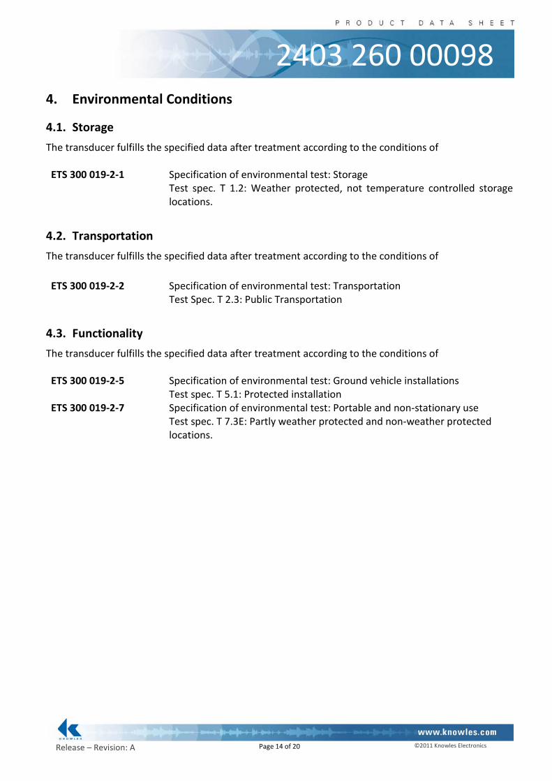
4. Environmental Conditions
4.1. Storage The transducer fulfills the specified data after treatment according to the conditions of ETS 300 019-2-1 Specification of environmental test: Storage
Test spec. T 1.2: Weather protected, not temperature controlled storage locations.
4.2. Transportation The transducer fulfills the specified data after treatment according to the conditions of ETS 300 019-2-2 Specification of environmental test: Transportation
Test Spec. T 2.3: Public Transportation
4.3. Functionality The transducer fulfills the specified data after treatment according to the conditions of ETS 300 019-2-5 Specification of environmental test: Ground vehicle installations
Test spec. T 5.1: Protected installation ETS 300 019-2-7 Specification of environmental test: Portable and non-stationary use
Test spec. T 7.3E: Partly weather protected and non-weather protected locations.

Page 15 of 20
©2011 Knowles Electronics Release – Revision: A
2403 260 00098
5. Environmental Tests
5.1. Qualification tests According to our milestone plan (Product Creation Process), a complete qualification test will be done at design validation of products manufactured under serial conditions. 1x per year and product family a requalification takes place. The qualification process covers all tests described under 4.5 and a complete inspection.
5.2. Reliability tests 1x per month and product family samples are taken and submitted to tests described under 4.5.2
5.3. Sample size, sequence Unless otherwise stated 20 arbitrary new samples will be used to perform each test for both, qualifica-tion and requalification test as described under 4.1 and 4.2.
5.4. Period of shelf-life The period of shelf-life is 2 years.
5.5. Testing procedures
5.5.1. Storage tests
5.5.1.1. Cold storage test
Parameter Test Method and Con-ditions
Duration Evaluation Standard
Low Temperature Storage
(Ref. EN 60068-2-1)
-40°C rel. humidity not con-
trolled
168h Measurements after 2 hours recovery time.
All samples fully operable. All acoustical parameters ac-
cording specification with toler-ances increased by 50 %.
5.5.1.2. Heat storage test
Parameter Test Method and Con-ditions
Duration Evaluation Standard
Dry Heat Storage (Ref. EN 60068-2-2)
+85°C rel. humidity not con-
trolled
168h Measurements after 2 hours recovery time.
All samples fully operable. All acoustical parameters ac-
cording specification with toler-ances increased by 50 %.

Page 16 of 20
©2011 Knowles Electronics Release – Revision: A
2403 260 00098
5.5.1.3. Temperature cycle test
Parameter Test Method and Con-ditions
Duration Evaluation Standard
Change of Temperature (Ref. EN 60068-2-14)
-40°C/+85°C Transition time <3 min. See Figure 4-1 below
5 cycles >2h for each temperature
Measurements after 2 hours recovery time.
All samples fully operable. All acoustical parameters ac-
cording specification with toler-ances increased by 50 %.
-40°C
+85°C
2h 2h3m 3m
2h 2h3m 3m
2h 2h3m 3m
2h 2h3m 3m 3m 3m
2h 2h
Figure 4-1: Temperature Cycle Test
5.5.1.4. Temperature/humidity cycle test
Parameter Test Method and Con-ditions
Duration Evaluation Standard
Damp heat, cyclic (Ref. IEC 60068-2-30)
+25°C/+55°C 90% to 95% RH.
Temp. change time <3h See Figure 4-2 below
Caution: no condensed water on products!
6 cycles. 12h at each temperature
Measurements after 2 hours recovery time.
All samples fully operable. All acoustical parameters ac-
cording specification with toler-ances increased by 50 %.
+25°C
+55°C
9h 9h3h 3h
9h 9h3h 3h
9h 9h3h 3h
9h 9h3h 3h
9h 9h3h 3h
9h 9h3h 3h
Figure 4-2: Temperature / Relative Humidity Cycle Test

Page 17 of 20
©2011 Knowles Electronics Release – Revision: A
2403 260 00098
5.5.2. Operating tests
5.5.2.1. Cold operation test
Parameter Test Method and Con-ditions
Duration Evaluation Standard
Cold Operation Test (Ref. EN 60068-2-1)
-20°C rel. humidity not con-
trolled signal acc. chapter 3.3
72h Measurements after 2 hours recovery time.
All samples fully operable. THD may be increased after test. All other acoustical pa-
rameters according specifica-tion with tolerances increased
by 50 %.
5.5.2.2. Heat operation test
Parameter Test Method and Con-ditions
Duration Evaluation Standard
Dry Heat Operation (Ref. EN 60068-2-2)
+70°C rel. humidity not con-
trolled signal acc. chapter 3.3
500h Measurements after 2 hours recovery time.
All samples fully operable. The allowable change in sensi-tivity shall not be greater than 3 dB. All other acoustical parame-ters according specification with tolerances increased by 50 %.
5.5.3. Salt mist test
Parameter Test Method and Con-ditions
Duration Evaluation Standard
Salt Mist (Ref. IEC60068-2-52,
Kb / Severity 2
The part must be sub-jected to 2 hours spray of 5% NaCl salt mist, at
35°C then be left at 40°C and 95% RH for
22h.
3 cycles The samples shall be washed after the test with distilled water
and dried at T< 50°C. Component may have reduced
performance, but must still function properly. The allowable
sensitivity difference shall not be greater than ±3dB from
initial sensitivity.

Page 18 of 20
©2011 Knowles Electronics Release – Revision: A
2403 260 00098
5.5.4. Guided free fall test - protected product
Parameter Test Method and Con-ditions
Conditions / Sample size
Evaluation Standard
Mechanical shock (Ref. IEC60068-2-32
Ed), Procedure 1
Speaker in drop test box or representative
mechanics from a height of 1.5m onto
concrete floor.
30 units Two drops on
each side (2x6) One drop on each edge (1x12) Two
drops on each corner (2x8) (40 drops in
total)
Component may have reduced performance, but must still
function properly. The allowable sensitivity difference shall not
be greater than ±3dB from initial sensitivity.
5.5.5. Random free fall test (tumble test) – protected product
Parameter Test Method and Condi-tions
Conditions / Sample size
Evaluation Standard
Impact durability (in a Tumble Tester)
(Ref. IEC60068-2-32 Ed)
(SPR a7.1.1)
Speaker in drop test box or representative me-
chanics. Random drops on steel base.
30 units 180 drops, 1m DUT power off
Component may have reduced performance, but must still
function properly. The allowa-ble sensitivity difference shall
not be greater than ±3 dB from initial sensitivity.
5.5.6. Resistance to electrostatic discharge
Parameter Test Method and Condi-tions
Conditions / Sample size
Evaluation Standard
Resistance to ESD IEC61000-4-2 Level 4
(SPR c 2.5.1)
One pole is grounded and the ESD pulse is applied
to the other pole. The speaker must be stressed first with one polarisation and then with the other
polarisation. DUT must be discharged between each
ESD exposure. Level 4: contact +/- 8kV,
air +/- 15kV
10 exposures on each polarity / 5
units DUT Power off
All samples fully operable. All acoustical parameters
according specification with tolerances increased by
50%.
Page 19 of 20
©2011 Knowles Electronics Release – Revision: A
2403 260 00098
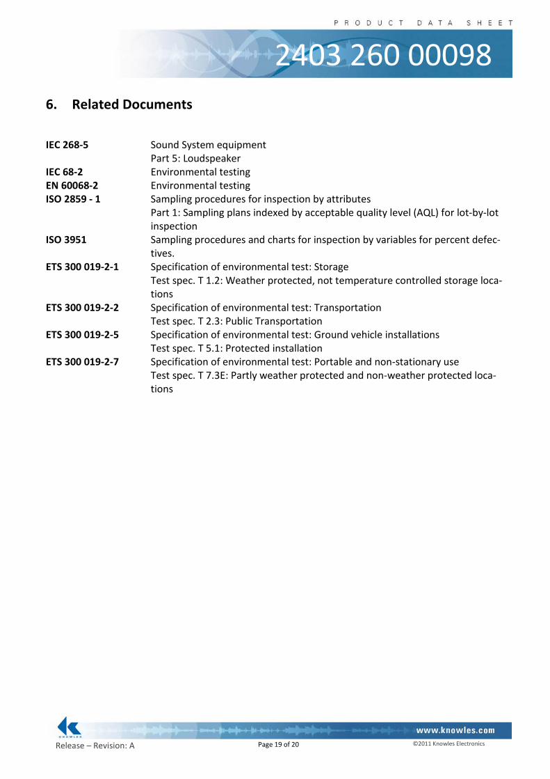
6. Related Documents
IEC 268-5 Sound System equipment Part 5: Loudspeaker IEC 68-2 Environmental testing EN 60068-2 Environmental testing ISO 2859 - 1 Sampling procedures for inspection by attributes
Part 1: Sampling plans indexed by acceptable quality level (AQL) for lot-by-lot inspection
ISO 3951 Sampling procedures and charts for inspection by variables for percent defec-tives.
ETS 300 019-2-1 Specification of environmental test: Storage Test spec. T 1.2: Weather protected, not temperature controlled storage loca-
tions ETS 300 019-2-2 Specification of environmental test: Transportation Test spec. T 2.3: Public Transportation ETS 300 019-2-5 Specification of environmental test: Ground vehicle installations Test spec. T 5.1: Protected installation ETS 300 019-2-7 Specification of environmental test: Portable and non-stationary use Test spec. T 7.3E: Partly weather protected and non-weather protected loca-
tions
Page 20 of 20
©2011 Knowles Electronics Release – Revision: A
2403 260 00098
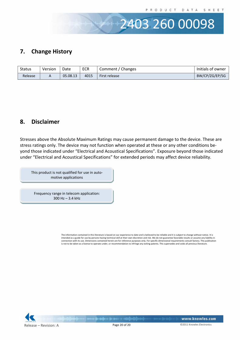
7. Change History
Status Version Date ECR Comment / Changes Initials of owner
Release A 05.08.13 4015 First release BW/CP/ZG/EP/SG
8. Disclaimer
Stresses above the Absolute Maximum Ratings may cause permanent damage to the device. These are stress ratings only. The device may not function when operated at these or any other conditions be-yond those indicated under “Electrical and Acoustical Specifications”. Exposure beyond those indicated under “Electrical and Acoustical Specifications” for extended periods may affect device reliability.
The information contained in this literature is based on our experience to date and is believed to be reliable and it is subject to change without notice. It is intended as a guide for use by persons having technical skill at their own discretion and risk. We do not guarantee favorable results or assume any liability in connection with its use. Dimensions contained herein are for reference purposes only. For specific dimensional requirements consult factory. This publication is not to be taken as a license to operate under, or recommendation to infringe any exiting patents. This supersedes and voids all previous literature.
This product is not qualified for use in auto-motive applications
Frequency range in telecom application: 300 Hz – 3.4 kHz