Embed Size (px)
Citation preview

Instruction ManualCOBRADry Screw Vacuum PumpsBA 0100 C
0870211637/-_en / Original instructions / Modifications reserved 14/09/2018
Ateliers Busch S.A.Zone industrielle, 2906 ChevenezSwitzerland

Table of Contents
2 / 24 0870211637_BA0100C_-_IM_en
Table of Contents1 Safety........................................................................................................................... 3
2 Product Description ..................................................................................................... 4
2.1 Operating Principle...............................................................................................5
2.2 Application ...........................................................................................................5
2.3 Drive Variants.......................................................................................................5
2.4 Standard Features.................................................................................................52.4.1 Wheels ......................................................................................................52.4.2 Emergency Stop Switch..............................................................................52.4.3 I/O and Communication Port (With VFD Only) .........................................52.4.4 Silencer ......................................................................................................6
2.5 Optional Accessories.............................................................................................62.5.1 Nitrogen System ........................................................................................6
3 Transport ..................................................................................................................... 6
4 Storage......................................................................................................................... 7
5 Installation................................................................................................................... 7
5.1 Installation Conditions ..........................................................................................7
5.2 Connecting Lines / Pipes ......................................................................................85.2.1 Suction Connection....................................................................................85.2.2 Discharge Connection................................................................................85.2.3 Nitrogen System Connection (Optional) ....................................................9
5.3 Earth Connection..................................................................................................10
5.4 Filling Oil ..............................................................................................................10
5.5 Electrical Connection ............................................................................................115.5.1 Voltage Switch 208 - 400 V.......................................................................12
5.6 I/O and Communication Port Schematic (With VFD Only) ...................................12
6 Commissioning............................................................................................................ 13
6.1 Conveying Condensable Vapours .........................................................................14
6.2 Restart Procedure .................................................................................................14
7 Maintenance ................................................................................................................ 14
7.1 Maintenance Schedule..........................................................................................15
7.2 Oil Level Inspection ..............................................................................................15
7.3 Oil Colour Inspection............................................................................................16
7.4 Oil Change...........................................................................................................16
8 Overhaul...................................................................................................................... 18
9 Decommissioning ........................................................................................................ 18
9.1 Dismantling and Disposal......................................................................................19
10 Spare Parts ................................................................................................................... 19
11 Troubleshooting........................................................................................................... 19
12 Technical Data ............................................................................................................. 21
13 Oil ............................................................................................................................... 21
14 EU Declaration of Conformity ...................................................................................... 22

Safety | 1
0870211637_BA0100C_-_IM_en 3 / 24
1 SafetyPrior to handling the machine, this instruction manual should be read and understood. Ifanything needs to be clarified, please contact your Busch representative.
Read this manual carefully before use and keep for future reference.
This instruction manual remains valid as long as the customer does not change anythingon the product.
The machine is intended for industrial use. It must be handled only by technically trainedpersonnel.
Always wear appropriate personal protective equipment in accordance with the localregulations.
The machine has been designed and manufactured according to state-of-the-art meth-ods. Nevertheless, residual risks may remain. This instruction manual highlights potentialhazards where appropriate. Safety notes and warning messages are tagged with one ofthe keywords DANGER, WARNING, CAUTION, NOTICE and NOTE as follows:
DANGER... indicates an imminent dangerous situation that will result in death or serious injuries ifnot prevented.
WARNING... indicates a potentially dangerous situation that could result in death or serious injuries.
CAUTION... indicates a potentially dangerous situation that could result in minor injuries.
NOTICE... indicates a potentially dangerous situation that could result in damage to property.
NOTE... indicates helpful tips and recommendations, as well as information for efficient andtrouble-free operation.

2 | Product Description
4 / 24 0870211637_BA0100C_-_IM_en
2 Product DescriptionCOM
4x WHL
OFP EB IN NP
OUT ECPNC
AF
ESS, MSH MC
EDPSI
VFDOSGDGVMSS VSODP
AF Axial fan COM I/O and communication port (with VFDonly)
DGV Dilution gas valve (Optional) EB Eye bolt
ECP Earth connection (machine) EDP Electrical data plate
ESS Emergency stop switch IN Inlet connection
MC Mains connection MSH Main switch
MSS Motor safety switch NC Nitrogen connection (Optional)
NP Nameplate OFP Oil fill plug
ODP Oil drain plug OSG Oil sight glass
OUT Discharge connection SI Silencer
VFD Variable-frequency drive (Optional) VS Voltage switch (with VFD only)
WHL Wheels
NOTETechnical term.
In this instruction manual, we consider that the term ‘machine’ refers to the ‘vacuumpump’.

Product Description | 2
0870211637_BA0100C_-_IM_en 5 / 24
2.1 Operating Principle
The machine works on the one-stage, twin-screw pump principle.
Two screw rotors are rotating inside the cylinder. The pumped medium is trappedbetween the cylinder and screw chambers, compressed, and transported to the gas out-let. During the compression process, the two screw rotors do not come into contact witheach other nor with the cylinder. There is no need for a lubrication or an operating fluidin the compression chamber.
The COBRA BA is fully air-cooled thanks to an integrated fan in the protective hood.
2.2 ApplicationThe machine is intended for the suction of air and other dry, toxic, non-aggressive andnon-explosive gases.
Conveying of other media leads to an increased thermal and/or mechanical load on themachine and is permissible only after a consultation with Busch.
The machine is intended for the placement in a non-potentially explosive environment.
The machine is suitable for continuous operation but limited to a suction pressure of 150hPa (mbar). The machine is allowed to operate at atmospheric pressure for up to 5minutes.
Permitted environmental conditions, see Technical Data [► 21].
2.3 Drive VariantsThe machine can be equipped with either a direct drive or a variable-frequency drive(VFD).
2.4 Standard Features
2.4.1 WheelsFour wheels are fitted to the bottom of the machine to facilitate transportation and in-stallation.
2.4.2 Emergency Stop SwitchThe machine is equipped in standard with an emergency stop switch (ESS).
2.4.3 I/O and Communication Port (With VFD Only)The D-Sub 15 supports maintained dry contact remote control and monitoring of themachine.

3 | Transport
6 / 24 0870211637_BA0100C_-_IM_en
2.4.4 SilencerA silencer at the discharge connection (OUT) is provided as standard to reduce the ex-haust gas noise.
2.5 Optional Accessories
2.5.1 Nitrogen SystemThe nitrogen connection (NC) supplies nitrogen or clean dry compressed air for:
– The barrier gas system (gas sealing between the compression chamber and gears/bearing housing).
– The dilution gas system.
3 Transport
WARNINGSuspended load.
Risk of severe injury!
• Do not walk, stand or work under suspended loads.
• Make sure that the eyebolt (EB) is in faultless condition, fully screwed in and tightenedby hand.
Machine weight:see the technical data or the nameplate (NP)
• Check the machine for transport damage.
If the machine is secured to a base plate:
• Remove the machine from the base plate.

Storage | 4
0870211637_BA0100C_-_IM_en 7 / 24
4 Storage• Seal all apertures with adhesive tape or reuse provided caps.
NOTICELong storage time.
Risk of damage to the machine!
• Due to a long storage time the capacitors of the variable-frequency drive can lose effi-ciency because of electrochemical processes. In worst case it can leads to a shirt-circuitand therefore to a damage to the variable-frequency drive of the machine.
• Connect the machine every 18 months for 30 minutes to the mains.
If the machine is to be stored for more than 3 months:
• Wrap the machine in a corrosion inhibiting film.
• Store the machine indoors, dry, dust free and if possible in original packagingpreferably at temperatures between -20 ... 60 °C.
5 Installation
5.1 Installation Conditions
NOTICEUse of the machine outside of the permitted installation conditions.
Risk of premature failure!
Loss of efficiency!
• Take care that the installation conditions are fully complied with.
~50 cm~20 cm
~20 cm
~20 cm
• Make sure that the environment of the machine is not potentially explosive.
• Make sure that the ambient conditions comply with the Technical Data [► 21].• Make sure that the installation space or location is vented such that sufficient cooling
of the machine is provided.
• Make sure that cooling air inlets and outlets are not covered or obstructed and thatthe cooling air flow is not affected adversely in any other way.

5 | Installation
8 / 24 0870211637_BA0100C_-_IM_en
• Make sure that enough space remains for maintenance work.
• Make sure that the machine is placed or mounted horizontally, a maximum of 1° inany direction.
• Check the oil level, see Oil Level Inspection [► 15].• Make sure that all provided covers, guards, hoods, etc. are mounted.
If the machine is installed at an altitude greater than 1000 meters above sea level:
• Contact your Busch representative, the motor should be derated or the ambienttemperature limited.
5.2 Connecting Lines / Pipes• Remove all protective caps before installation.
• Make sure that the connection lines cause no stress on the machine‘s connection; ifnecessary use flexible joints.
• Make sure that the line size of the connection lines over the entire length is at least aslarge as the connections of the machine.
In case of very long connection lines it is advisable to use larger line sizes in order toavoid a loss of efficiency. Seek advice from your Busch representative.
5.2.1 Suction Connection
WARNINGUnprotected suction connection.
Risk of severe injury!
• Keep long hair, loose articles of clothing, etc. away from suction connection.
NOTICEIngress of foreign objects or liquids.
Risk of damage to the machine!
If the inlet gas contains dust or other foreign solid particles:
• Install a suitable filter (5 micron or less) upstream from the machine.
Connection size:
– ISO-KF 50
If the machine is used as part of a vacuum system:
• Busch recommends the installation of an isolation valve in order to prevent themachine from turning backwards.
5.2.2 Discharge ConnectionConnection size:
– ISO-KF 40
• Make sure that the discharged gas will flow without obstruction. Do not shut off orthrottle the discharge line or use it as a pressurised air source.
• Make sure that the counter pressure (also termed back pressure) at the discharge con-nection (OUT) does not exceed the maximum allowable discharge pressure, see Tech-nical Data [► 21].

Installation | 5
0870211637_BA0100C_-_IM_en 9 / 24
5.2.3 Nitrogen System Connection (Optional)
DGVNC
DGV Dilution gas valve NC Nitrogen connection
• Connect the nitrogen connection (NC) to the gas supply.
Connection size:
– G1/4, ISO 228-1 (NC)
To access the dilution gas valve (DGV):
• Remove the two cruciform head screws at the top corners of the side cover.
• Lift the side cover to remove it from the frame.
• Make sure that the gas complies with the following requirements:Gas type Dry nitrogen or air
Gas temperature °C 0 ... 60
Maximum gas supply pressure bar 6
Minimum gas supply pressure bar 2.7
Filtration µm 5
Air quality (only for air) Acc. To ISO 8573-1 Class 5.4.4.
Flow rate (with DGV closed): SLM* 19 ... 33
Flow rate (with DGV open): SLM* 25 ... 51
* standard litre per minute

5 | Installation
10 / 24 0870211637_BA0100C_-_IM_en
5.3 Earth Connection• Connect the earth connection of the machine (ECP).
ECP
5.4 Filling Oil
NOTICEUse of an inappropriate oil.
Risk of premature failure!
Loss of efficiency!
• Only use an oil type which has previously been approved and recommended byBusch.
For oil type and oil capacity see Technical Data [► 21] and Oil [► 21].
4x
2x
Use a crussiform screwdriver
Use a crussiform screwdriverRemove side cover
Remove top cover

Installation | 5
0870211637_BA0100C_-_IM_en 11 / 24
1
2Busch Oil
3
MAXMIN
4
Check oil level
Oil sight glass
When the oil filling is achieved:
• Write down the oil change date on the sticker.
Last oil change
__ / __ / ____
Oil type see nameplate
Change interval see
instruction manual
If there is no sticker (part no. 0565 568 959) on the machine:
• Order it from your Busch representative.
5.5 Electrical Connection• Wire the mating connector (delivered loose) in accordance with the scheme below:
Mains connection (MC) 4-pin connector
1 2
3
1 = Phase 12 = Phase 23 = Phase 3(4) = Earth
• Electrically connect the machine directly to the mains connection (MC).

5 | Installation
12 / 24 0870211637_BA0100C_-_IM_en
5.5.1 Voltage Switch 208 - 400 V• Make sure that the main switch (MSH) is in “OFF” position.
• Select the needed voltage from the voltage switch (VS)(factory default setting ► 400 V).
The 208 V setting is used for 200-240 VAC and the 400 V switch position is used for380-480 VAC.
2x
400 V
208 V
Use a crussiformscrewdriver
Remove side cover
5.6 I/O and Communication Port Schematic (WithVFD Only)Connector: D-Sub15, 15-pin, female
8 1
915
Pin Nr. Description
1 N/A
2 Digital Input 2 Start pumpOpen: StopClosed: Start
3 … 4 N/A5 24 V OUT
6 Digital Input 1 Preset speedDI1 = 0 ► 50 HzDI2 = 1 ► 60 Hz
7 Fault relay IN8 Fault relay OUT9 … 14 N/A15 24 V OUT Power supply (max. 10 mA)
Power supply (max. 10 mA)N/A
N/ASignal
Contact NC (normally closed)Umax = 250 VDC / Imax = 2 A
N/A

Commissioning | 6
0870211637_BA0100C_-_IM_en 13 / 24
6 Commissioning
NOTICELubricating a dry running machine (compression chamber).
Risk of damage to the machine!
• Do not lubricate the compression chamber of the machine with oil or grease.
NOTICERunning without air-cooled system.
Risk of damage to the machine!
• Make sure that the fan (AF) is running whenever the machine is running.
CAUTIONDuring operation the surface of the machine may reach temperatures of more than70°C.
Risk of burns!
• Avoid contact with the machine during and directly after operation.
CAUTIONNoise of running machine.
Risk of damage to hearing!
If persons are present in the vicinity of a non noise insulated machine over extendedperiods:
• Make sure that ear protection is being used.
• Make sure that the installation conditions (see Installation Conditions [► 7]) are com-plied with.
If the machine is equipped with a nitrogen system:
• Turn on the nitrogen supply.
• Switch on the machine
• Make sure that the maximum permissible number of starts does not exceed 6 startsper hour.
• Make sure that the operating conditions are complied with, see Technical Data[► 21].
• After a few minutes of operation, perform an Oil Level Inspection [► 15].As soon as the machine is operated under normal operating conditions:
• Measure the motor current and record it as reference for future maintenance andtroubleshooting work.

7 | Maintenance
14 / 24 0870211637_BA0100C_-_IM_en
6.1 Conveying Condensable VapoursThe machine, equipped with a dilution gas sytem, is suitable for the conveyance of con-densable vapour within the gas flow.
START
Open the dilutiongas valve (DGV)
Warm up themachine
30 minutes 30 minutes
• Open the inletvalve
• Perform the process• Close the inlet
valve
Close the dilution gasvalve (DGV)
END
6.2 Restart ProcedureIf the machine has stopped unintentionally:
• Find out why the machine has stopped and solve the problem, see Troubleshoot-ing [► 19].
• Let the machine cool down (approx. 1 hour).
• Switch on the motor safety switch (MSS).
• Start up the machine again with the main switch (MSH).
7 Maintenance
WARNINGMachines contaminated with hazardous material.
Risk of poisoning!
Risk of infection!
If the machine is contaminated with hazardous material:
• Wear appropriate personal protective equipment.
CAUTIONHot surface.
Risk of burns!
• Prior to any action requiring touching the machine, let the machine cool down first.
NOTICEUsing inappropriate cleaners.
Risk of removing safety stickers and protective paint!
• Do not use incompatible solvents to clean the machine.

Maintenance | 7
0870211637_BA0100C_-_IM_en 15 / 24
NOTICEFailing to properly maintain the machine.
Risk of premature failure!
Loss of efficiency!
• Respect the maintenance intervals or ask your Busch representative for service.
• Shut down the machine and lock against inadvertent start up.
If the machine is equipped with a barrier gas system:
• Close the barrier gas supply.
• Vent the connected lines to atmospheric pressure.
If necessary:
• Disconnect all connections.
7.1 Maintenance ScheduleThe maintenance intervals depend very much on the individual operating conditions. Theintervals given below are desired to be considered as starting values which should beshortened or extended as appropriate. Particularly harsh applications or heavy duty oper-ation, such as high dust loads in the environment or in the process gas, other contamina-tion or ingress of process material, can make it necessary to shorten the maintenance in-tervals significantly.Interval Maintenance work
Monthly • Check the oil level, see Oil Level Inspection [► 15].• Check the machine for oil leaks - in case of leaks have
the machine repaired (contact Busch).
Yearly • Carry out a visual inspection and clean the machinefrom dust and dirt.
• Check the electrical connections and the monitoringdevices.
Every 16000 hours, at thelatest after 4 years
• Change the oil of the gear and bearings, see OilChange [► 16].
• If necessary, have a major overhaul on the machine(contact Busch).
7.2 Oil Level Inspection• Shut down the machine.
• When the machine is stopped, wait 1 minute before checking the oil level.
MAXMIN
MAXMIN
MAXMIN
• Fill up if necessary, see Oil Filling [► 10].

7 | Maintenance
16 / 24 0870211637_BA0100C_-_IM_en
7.3 Oil Colour Inspection
WARNINGOil “YLC 250 B” contaminated chemically or by foreign bodies.
Risk of explosion!
If the oil becomes dark:
• Contact your Busch representative without delay.
• Make sure that the oil is always transparent.
If the oil becomes dark, white or looks different from the initial colour:
• Change the oil immediately, see Oil Change [► 16].You can consult your Busch representative in order to find out why this colour changehas occurred.
7.4 Oil Change
NOTICEUse of an inappropriate oil.
Risk of premature failure!
Loss of efficiency!
• Only use an oil type which has previously been approved and recommended byBusch.
1
2
Drain pan

Maintenance | 7
0870211637_BA0100C_-_IM_en 17 / 24
For oil type and oil capacity see Technical Data [► 21] and Oil [► 21].
4x
2x
Use a crussiform screwdriver
Use a crussiform screwdriverRemove side cover
Remove top cover
1
2Busch Oil
3
MAXMIN
4
Check oil level
Oil sight glass
When the oil filling is achieved:
• Write down the oil change date on the sticker.

8 | Overhaul
18 / 24 0870211637_BA0100C_-_IM_en
Last oil change
__ / __ / ____
Oil type see nameplate
Change interval see
instruction manual
If there is no sticker (part no. 0565 568 959) on the machine:
• Order it from your Busch representative.
8 Overhaul
NOTICEImproper assembly.
Risk of premature failure!
Loss of efficiency!
• It is highly recommended that any dismantling of the machine that goes beyond any-thing that is described in this manual should be done through Busch.
WARNINGMachines contaminated with hazardous material.
Risk of poisoning!
Risk of infection!
If the machine is contaminated with hazardous material:
• Wear appropriate personal protective equipment.
In case of the machine having conveyed gas that was contaminated with foreign materi-als which are dangerous to health:
• Decontaminate the machine as well as possible and state the contamination statusin a ‘Declaration of Contamination’.
Busch will only accept machines that come with a completely filled in and legally bindingsigned ‘Declaration of Contamination’.(Form downloadable from www.buschvacuum.com)
9 Decommissioning• Shut down the machine and lock against inadvertent start up.
If the machine is equipped with a barrier gas system:
• Close the barrier gas supply.
• Vent the connected lines to atmospheric pressure.
• Disconnect all connections.
If the machine is going to be stored:
• See Storage [► 7].

Spare Parts | 10
0870211637_BA0100C_-_IM_en 19 / 24
9.1 Dismantling and Disposal• Separate special waste from the machine.
• Dispose of special waste in compliance with applicable regulations.
• Dispose of the machine as scrap metal.
10 Spare Parts
NOTICEUse of non-Busch genuine spare parts.
Risk of premature failure!
Loss of efficiency!
• The exclusive use of Busch genuine spare parts and consumables is recommended forthe proper function of the machine and for granting of warranty.
There is no standard spare parts kits available for this product, if you require Busch gen-uine parts:
• Contact your Busch representative for the detailed spare parts list.
11 TroubleshootingProblem Possible Cause Remedy
The machine does not start. The machine is not suppliedwith the correct voltage.
• Check the power supply.
Internal parts are worn ordamaged
• Repair the machine (con-tact Busch).
The motor safety switch(MSS) has tripped.
• Check the electrical in-stallation.
• Turn on the motor safetyswitch.
The motor is defective. • Repair the machine (con-tact Busch).
The machine does not reachthe usual pressure on thesuction connection.
Suction lines are too long orsection diameter is too small.
• Use larger diameter orshorter lines.
• Seek advice from yourlocal Busch representa-tive.
Measurement method orreading is false.
• Check the gauge, checkultimate pressure directlyat isolated inlet connec-tion.
Excessive counter pressure • Make sure internal or ex-ternal check valve is notstuck.
Leak in the system. • Repair leak.
Internal parts are worn ordamaged.
• Repair the machine (con-tact Busch).

11 | Troubleshooting
20 / 24 0870211637_BA0100C_-_IM_en
The machine runs too hot. Ambient temperature toohigh.
• Observe the permittedambient temperature, seeTechnical Data [► 21].
The fan inlet (AF) is dirty orobstructed.
• Clean it and make surethat the air flow path isclear of all obstacles.
Temperature of the processgases at the inlet too high.
• Observe the permittedgas inlet temperature, seeTechnical Data [► 21].
The machine runs very nois-ily.
Wrong oil quantity or un-suitable oil type.
• Use one of the recom-mended oils in the correctquantity, see Oil [► 21].
Defective gears, bearings orcoupling element.
• Repair machine (contactBusch).
The oil is no longer transpar-ent
Oil change intervals are toolong.
• Drain the oil and fill innew oil, see Oil Change[► 16].
The machine runs too hot. • See problem "The ma-chine runs too hot".
The oil is emulsified due tocontamination by the pro-cess.
• Drain the oil and fill innew oil, see Oil Change[► 16].

Technical Data | 12
0870211637_BA0100C_-_IM_en 21 / 24
12 Technical DataBA 0100 C
Nominal pumping speed (50Hz / 60Hz) m³/h 85 / 105105*
Ultimate pressure hPa (mbar) abs.Torr
0.010.0075
Max. continuous suction pressure hPa (mbar) abs.Torr
150112.5
Max. allowable discharge pressure hPa (mbar) rel.PSIG
2002.9
Water vapour capacity g/h 1000
Leak rate (helium) mbar·L·s-1 (sccs) ≤1 x 10⁻⁶
Nominal motor rating (50Hz / 60Hz) kW 1.5 / 1.8
Nominal system rating* kW 2.2*
Power consumption at ultimate pressure (50Hz / 60Hz) kWh 1.1 / 1.251.3*
Operating voltages (50Hz / 60Hz) V 380-415 / 200-240
Operating voltages* (50Hz / 60Hz) V 208-240 / 380-480*
Nominal motor speed (50Hz / 60Hz) min-1 3000 / 36003600*
Noise level (EN ISO 2151) (50Hz / 60Hz) dB(A) 58
Ambient temperature range °C°F
0 … 4032 … 104
Oil capacity l 0.12
Dimensions (L x W x H) mm 634 x 304 x 338
Weight approx. kg 120
* with integrated variable-frequency drive
13 OilYLC 250 B
Part number 0.12 L packaging 0831 564 840
Part number 0.5 L packaging (~1 kg) 0831 131 400
14 | EU Declaration of Conformity
22 / 24 0870211637_BA0100C_-_IM_en
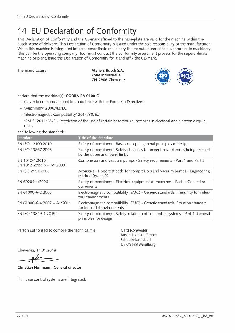
14 EU Declaration of ConformityThis Declaration of Conformity and the CE-mark affixed to the nameplate are valid for the machine within theBusch scope of delivery. This Declaration of Conformity is issued under the sole responsibility of the manufacturer.When this machine is integrated into a superordinate machinery the manufacturer of the superordinate machinery(this can be the operating company, too) must conduct the conformity assessment process for the superordinatemachine or plant, issue the Declaration of Conformity for it and affix the CE-mark.
The manufacturer Ateliers Busch S.A.Zone IndustrielleCH-2906 Chevenez
declare that the machine(s): COBRA BA 0100 C
has (have) been manufactured in accordance with the European Directives:
– ‘Machinery’ 2006/42/EC
– ‘Electromagnetic Compatibility’ 2014/30/EU
– ‘RoHS’ 2011/65/EU, restriction of the use of certain hazardous substances in electrical and electronic equip-ment
and following the standards.
Standard Title of the Standard
EN ISO 12100:2010 Safety of machinery - Basic concepts, general principles of design
EN ISO 13857:2008 Safety of machinery - Safety distances to prevent hazard zones being reachedby the upper and lower limbs
EN 1012-1:2010EN 1012-2:1996 + A1:2009
Compressors and vacuum pumps - Safety requirements - Part 1 and Part 2
EN ISO 2151:2008 Acoustics - Noise test code for compressors and vacuum pumps - Engineeringmethod (grade 2)
EN 60204-1:2006 Safety of machinery - Electrical equipment of machines - Part 1: General re-quirements
EN 61000-6-2:2005 Electromagnetic compatibility (EMC) - Generic standards. Immunity for indus-trial environments
EN 61000-6-4:2007 + A1:2011 Electromagnetic compatibility (EMC) - Generic standards. Emission standardfor industrial environments
EN ISO 13849-1:2015 (1) Safety of machinery - Safety-related parts of control systems - Part 1: Generalprinciples for design
Person authorised to compile the technical file: Gerd RohwederBusch Dienste GmbHSchauinslandstr. 1DE-79689 Maulburg
Chevenez, 11.01.2018
Christian Hoffmann, General director
(1) In case control systems are integrated.

Note

Argentinawww.busch-vacuum.com.ar
Australiawww.busch.com.au
Austriawww.busch.at
Belgiumwww.busch.be
Brazilwww.buschdobrasil.com.br
Canadawww.busch.ca
Chilewww.busch.cl
Chinawww.busch-china.com
Colombiawww.buschvacuum.co
Czech Republicwww.buschvacuum.cz
Denmarkwww.busch.dk
Finlandwww.busch.fi
Francewww.busch.fr
Germanywww.busch.de
Hungarywww.buschvacuum.hu
Indiawww.buschindia.com
Irelandwww.busch.ie
Israelwww.busch.co.il
Italywww.busch.it
Japanwww.busch.co.jp
Koreawww.busch.co.kr
Malaysiawww.busch.com.my
Mexicowww.busch.com.mx
Netherlandswww.busch.nl
New Zealandwww.busch.com.au
Norwaywww.busch.no
Peruwww.busch.com.pe
Polandwww.busch.com.pl
Portugalwww.busch.pt
Russiawww.busch.ru
Singaporewww.busch.com.sg
South Africawww.busch.co.za
Spainwww.buschiberica.es
Swedenwww.busch.se
Switzerlandwww.busch.ch
Taiwanwww.busch.com.tw
Thailandwww.busch.co.th
Turkeywww.buschvacuum.com
United Arab Emirateswww.busch.ae
United Kingdomwww.busch.co.uk
USAwww.buschusa.com
www.buschvacuum.com
Busch Vacuum Pumpsand SystemsAll over the World in Industry
0870211637/-_en / © Ateliers Busch S.A.