Embed Size (px)
Citation preview
24th ABCM International Congress of Mechanical Engineering December 3-8, 2017, Curitiba, PR, Brazil
COBEM-2017-2778
THE DEVELOPMENT OF A RACE CAR MONOCOQUE
Gustavo Gonçalves
Laura Farinasso Perucci
Rafael Peron de Marchi USP - Universidade of São Paulo, EESC –School of Engineering of São Carlos, Av. Trab. São-Carlense, 400 - Parque Arnold
Schimidt, São Carlos - SP, 13566-590, SP, Brasil
[email protected], [email protected], [email protected]
Abstract.This paper aims to present the analysis and development of a chassis for an academic competition of Formula
SAE (Society of Automotive Engineering). To achieve better handling and balance of the vehicle in relation to its
predecessor project it was used the finite element analysis (FEA) for numerical simulation. Then the model was validated
using experimental tests. During the design stage of the project several rule parameters were considered. Such as, safety
for the pilot, torsional stiffness, chassis behavior in situations of cornering, accelerations and braking, free and forced
vibrations as well as their respective free body and rigid body vibration modes. The present work also contemplates the
steps of confection of the monocoque and the choice of the materials considering cost-benefit rate.
Keywords:Formula SAE, Chassi, Monocoque, FEA, E14
1. INTRODUCTION
The biggest challenge in creating and building a chassis for a racing car lies in achieving a satisfactory relationship
between strength, weight, stiffness and cost. To be able to correlate these parameters simultaneously becomes an arduous
and complex task, because all the other subsystems of the vehicle depend exclusively on the final design of the chassis.
All this work can be facilitated by the use of computing tools. One of them is finite element analisys (FEA) the aim of
this work. The software used for all the simulations was the Ansys® Workbench v17. With this numerical method, it is
possible to simplify the creation and optimization of Monocoque prototyping. Excluding the need to create several
experimental models, since this requires time and money. Another important point is that the chassis model can not be
reused, so every year is necessary to create a new model (Formula SAE Rules, 2017-18)
2. METODOLOGIA
We can divide the methodology of this work into two main parts, the first one being the numerical methodology
where the techniques used to create the computational model of the monocoque are, and that we will refer to as E14 and
the experimental methodology that was used to validate the computational model.
2.1 Numeric
In this part of the work we will present the simulations that correspond to the maneuvers executed by the car E14
being that of acceleration, braking, curve, braking with curve and braking with acceleration, also an analysis of torsional
stiffness of the chassis and a modal analysis to validate the numerical model.
2.1.1 Creation of the computational model.
The geometry of the structure is defined by pilot positioning, safety rules established by the competition rules (Formula
SAE Rules, 2017-18), Suspension, steering, engine and transmission hardpoints.
For the creation of the Computer Aided Design (CAD) model, a technique known as cloud of points was used that
was connected by line segments as shown in Fig. (1). When using cloud of points to create the model, it is possible to
guarantee that there will be no error of geometry, commonly generated by importing into commercial software.
G. Gonçalves, L. Perucci, R. Marchi The Development of a Race car Monocoque
Figure 1: Isometric view of the chassis, cloud of interconnected points
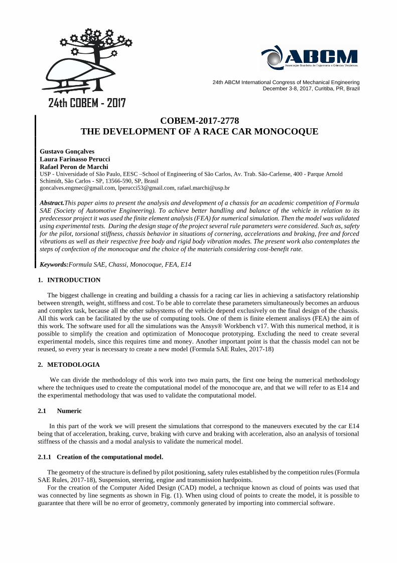
These sequences are a way of representing the steel tubes of the chassis structure, so we defined the profiles of each
of the tubes applied to the model that can be observed in Fig. (2). It is worth mentioning that in the design of the chassis
E14 tubes with different diameter and thickness were used. Seeking to use the smallest thickness allowed by the rule
(Formula SAE Rules, 2017-18).
Figure 2: Tubes applied to the structure
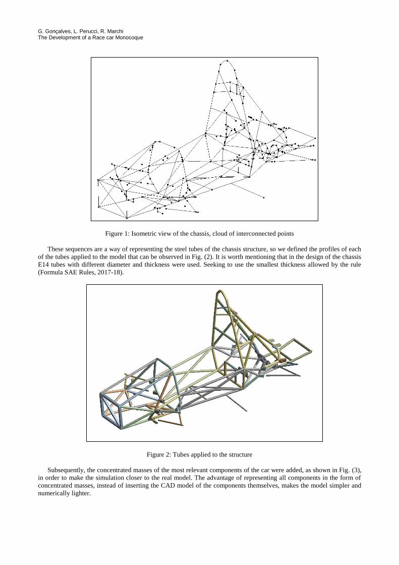
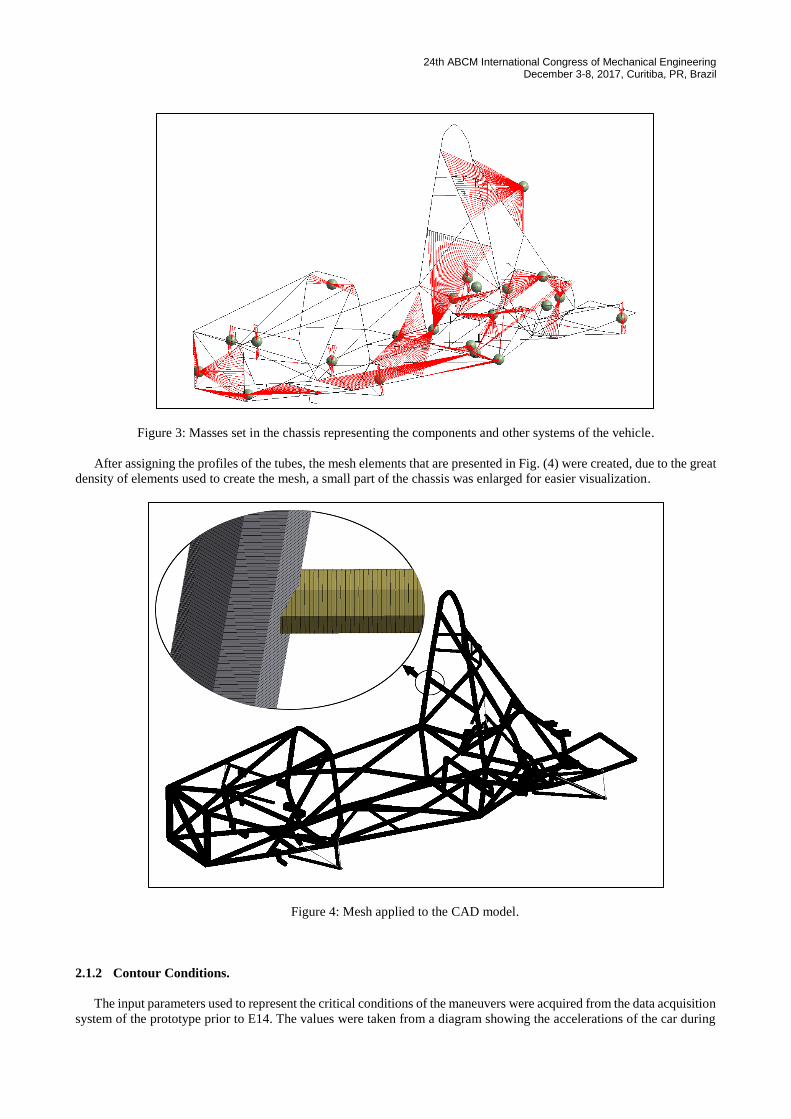
Subsequently, the concentrated masses of the most relevant components of the car were added, as shown in Fig. (3),
in order to make the simulation closer to the real model. The advantage of representing all components in the form of
concentrated masses, instead of inserting the CAD model of the components themselves, makes the model simpler and
numerically lighter.
24th ABCM International Congress of Mechanical Engineering December 3-8, 2017, Curitiba, PR, Brazil
Figure 3: Masses set in the chassis representing the components and other systems of the vehicle.
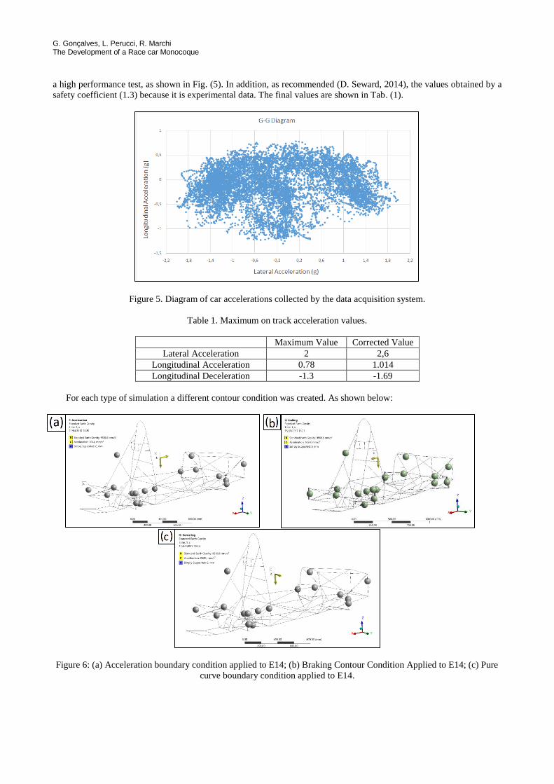
After assigning the profiles of the tubes, the mesh elements that are presented in Fig. (4) were created, due to the great
density of elements used to create the mesh, a small part of the chassis was enlarged for easier visualization.
Figure 4: Mesh applied to the CAD model.
2.1.2 Contour Conditions.
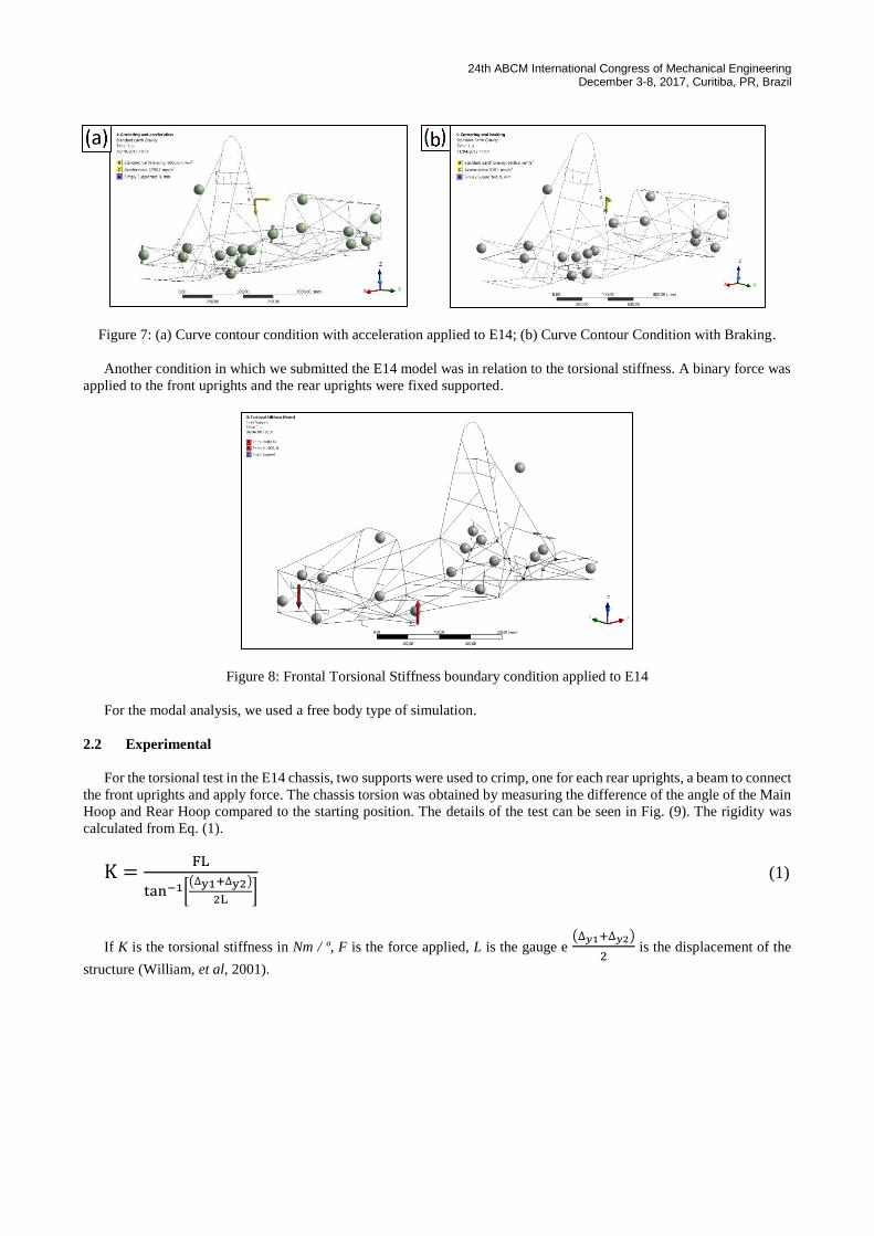
The input parameters used to represent the critical conditions of the maneuvers were acquired from the data acquisition
system of the prototype prior to E14. The values were taken from a diagram showing the accelerations of the car during
G. Gonçalves, L. Perucci, R. Marchi The Development of a Race car Monocoque
a high performance test, as shown in Fig. (5). In addition, as recommended (D. Seward, 2014), the values obtained by a
safety coefficient (1.3) because it is experimental data. The final values are shown in Tab. (1).
Figure 5. Diagram of car accelerations collected by the data acquisition system.
Table 1. Maximum on track acceleration values.
Maximum Value Corrected Value
Lateral Acceleration 2 2,6
Longitudinal Acceleration 0.78 1.014
Longitudinal Deceleration -1.3 -1.69
For each type of simulation a different contour condition was created. As shown below:
Figure 6: (a) Acceleration boundary condition applied to E14; (b) Braking Contour Condition Applied to E14; (c) Pure
curve boundary condition applied to E14.
24th ABCM International Congress of Mechanical Engineering December 3-8, 2017, Curitiba, PR, Brazil
Figure 7: (a) Curve contour condition with acceleration applied to E14; (b) Curve Contour Condition with Braking.
Another condition in which we submitted the E14 model was in relation to the torsional stiffness. A binary force was
applied to the front uprights and the rear uprights were fixed supported.
Figure 8: Frontal Torsional Stiffness boundary condition applied to E14
For the modal analysis, we used a free body type of simulation.
2.2 Experimental
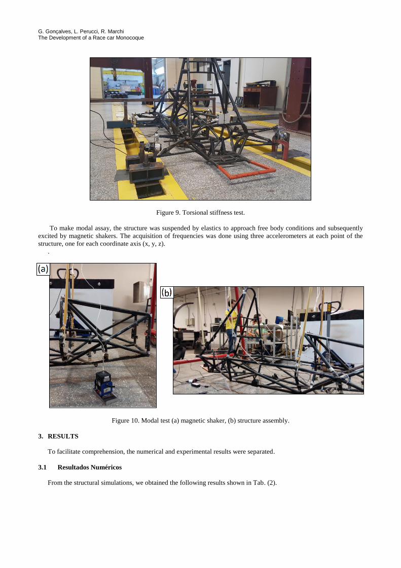
For the torsional test in the E14 chassis, two supports were used to crimp, one for each rear uprights, a beam to connect
the front uprights and apply force. The chassis torsion was obtained by measuring the difference of the angle of the Main
Hoop and Rear Hoop compared to the starting position. The details of the test can be seen in Fig. (9). The rigidity was
calculated from Eq. (1).
K =FL
tan−1[(∆y1+∆y2)
2L] (1)
If K is the torsional stiffness in Nm / º, F is the force applied, L is the gauge e (∆𝑦1+∆𝑦2)
2 is the displacement of the
structure (William, et al, 2001).
G. Gonçalves, L. Perucci, R. Marchi The Development of a Race car Monocoque
Figure 9. Torsional stiffness test.
To make modal assay, the structure was suspended by elastics to approach free body conditions and subsequently
excited by magnetic shakers. The acquisition of frequencies was done using three accelerometers at each point of the
structure, one for each coordinate axis (x, y, z).
.
Figure 10. Modal test (a) magnetic shaker, (b) structure assembly.
3. RESULTS
To facilitate comprehension, the numerical and experimental results were separated.
3.1 Resultados Numéricos
From the structural simulations, we obtained the following results shown in Tab. (2).
24th ABCM International Congress of Mechanical Engineering December 3-8, 2017, Curitiba, PR, Brazil
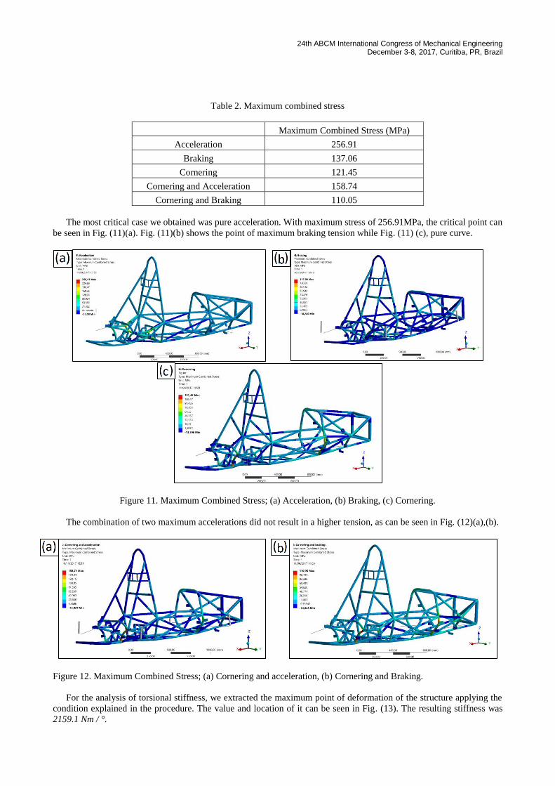
Table 2. Maximum combined stress
Maximum Combined Stress (MPa)
Acceleration 256.91
Braking 137.06
Cornering 121.45
Cornering and Acceleration 158.74
Cornering and Braking 110.05
The most critical case we obtained was pure acceleration. With maximum stress of 256.91MPa, the critical point can
be seen in Fig. (11)(a). Fig. (11)(b) shows the point of maximum braking tension while Fig. (11) (c), pure curve.
Figure 11. Maximum Combined Stress; (a) Acceleration, (b) Braking, (c) Cornering.
The combination of two maximum accelerations did not result in a higher tension, as can be seen in Fig. (12)(a),(b).
Figure 12. Maximum Combined Stress; (a) Cornering and acceleration, (b) Cornering and Braking.
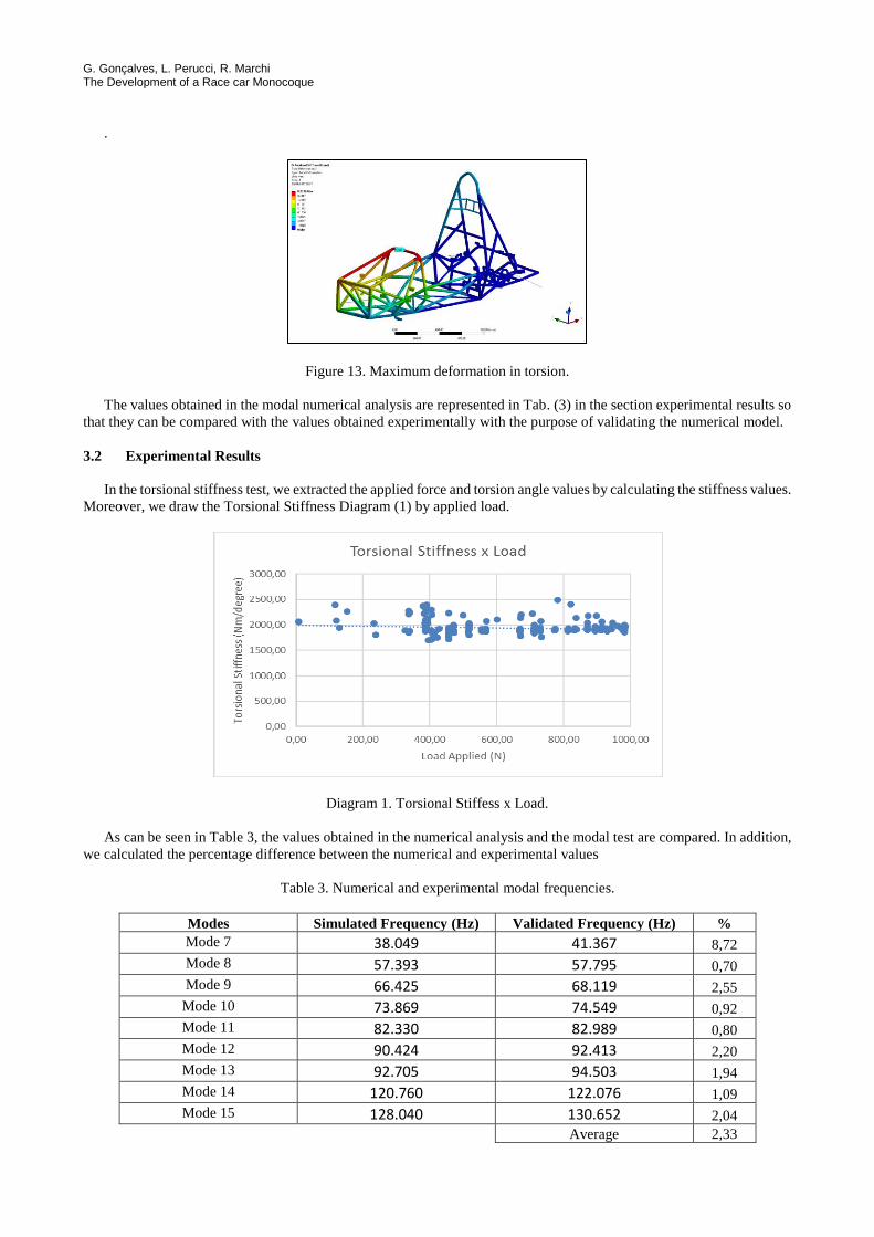
For the analysis of torsional stiffness, we extracted the maximum point of deformation of the structure applying the
condition explained in the procedure. The value and location of it can be seen in Fig. (13). The resulting stiffness was
2159.1 Nm / °.
G. Gonçalves, L. Perucci, R. Marchi The Development of a Race car Monocoque
.
Figure 13. Maximum deformation in torsion.
The values obtained in the modal numerical analysis are represented in Tab. (3) in the section experimental results so
that they can be compared with the values obtained experimentally with the purpose of validating the numerical model.
3.2 Experimental Results
In the torsional stiffness test, we extracted the applied force and torsion angle values by calculating the stiffness values.
Moreover, we draw the Torsional Stiffness Diagram (1) by applied load.
Diagram 1. Torsional Stiffess x Load.
As can be seen in Table 3, the values obtained in the numerical analysis and the modal test are compared. In addition,
we calculated the percentage difference between the numerical and experimental values
Table 3. Numerical and experimental modal frequencies.
Modes Simulated Frequency (Hz) Validated Frequency (Hz) %
Mode 7 38.049 41.367 8,72
Mode 8 57.393 57.795 0,70
Mode 9 66.425 68.119 2,55
Mode 10 73.869 74.549 0,92
Mode 11 82.330 82.989 0,80
Mode 12 90.424 92.413 2,20
Mode 13 92.705 94.503 1,94
Mode 14 120.760 122.076 1,09
Mode 15 128.040 130.652 2,04
Average 2,33
24th ABCM International Congress of Mechanical Engineering December 3-8, 2017, Curitiba, PR, Brazil
4. CONCLUSIONS
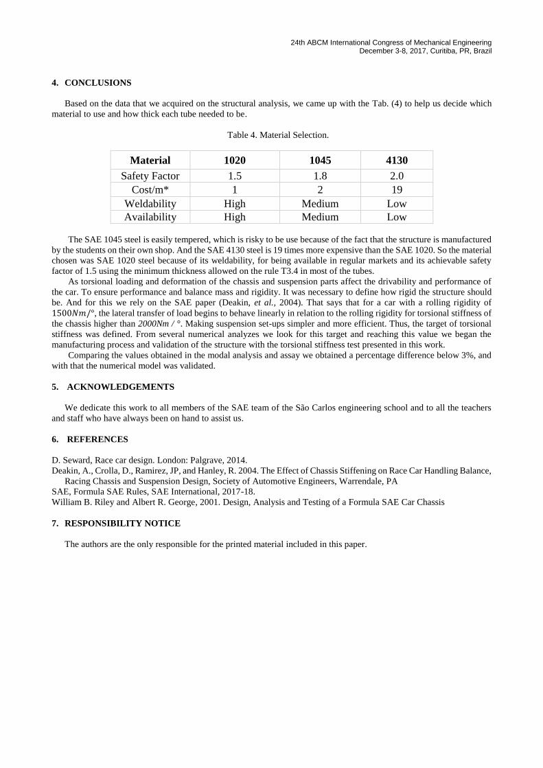
Based on the data that we acquired on the structural analysis, we came up with the Tab. (4) to help us decide which
material to use and how thick each tube needed to be.
Table 4. Material Selection.
Material 1020 1045 4130
Safety Factor 1.5 1.8 2.0
Cost/m* 1 2 19
Weldability High Medium Low
Availability High Medium Low
The SAE 1045 steel is easily tempered, which is risky to be use because of the fact that the structure is manufactured
by the students on their own shop. And the SAE 4130 steel is 19 times more expensive than the SAE 1020. So the material
chosen was SAE 1020 steel because of its weldability, for being available in regular markets and its achievable safety
factor of 1.5 using the minimum thickness allowed on the rule T3.4 in most of the tubes.
As torsional loading and deformation of the chassis and suspension parts affect the drivability and performance of
the car. To ensure performance and balance mass and rigidity. It was necessary to define how rigid the structure should
be. And for this we rely on the SAE paper (Deakin, et al., 2004). That says that for a car with a rolling rigidity of
1500𝑁𝑚/°, the lateral transfer of load begins to behave linearly in relation to the rolling rigidity for torsional stiffness of
the chassis higher than 2000Nm / °. Making suspension set-ups simpler and more efficient. Thus, the target of torsional
stiffness was defined. From several numerical analyzes we look for this target and reaching this value we began the
manufacturing process and validation of the structure with the torsional stiffness test presented in this work.
Comparing the values obtained in the modal analysis and assay we obtained a percentage difference below 3%, and
with that the numerical model was validated.
5. ACKNOWLEDGEMENTS
We dedicate this work to all members of the SAE team of the São Carlos engineering school and to all the teachers
and staff who have always been on hand to assist us.
6. REFERENCES
D. Seward, Race car design. London: Palgrave, 2014.
Deakin, A., Crolla, D., Ramirez, JP, and Hanley, R. 2004. The Effect of Chassis Stiffening on Race Car Handling Balance,
Racing Chassis and Suspension Design, Society of Automotive Engineers, Warrendale, PA
SAE, Formula SAE Rules, SAE International, 2017-18.
William B. Riley and Albert R. George, 2001. Design, Analysis and Testing of a Formula SAE Car Chassis
7. RESPONSIBILITY NOTICE
The authors are the only responsible for the printed material included in this paper.