Embed Size (px)
Citation preview
Product specifications
Physical characteristics
Volumea 33.2 cm3
Mass 79 g
H x W x D 66 mm x 51 mm x 13 mm
Surface area of device can 57 cm2
Radiopaque IDb PLS
Materials in contact with human tissuec
Titanium, polyurethane, silicone rubber, titanium dioxide
Battery Hybrid CFx lithium/silver vanadium oxide
a Volume with connector ports unplugged.b The radiopaque ID, which includes a Medtronic identifier symbol, can be viewed in a
fluoroscopic image of the device.c These materials have been successfully tested for the ability to avoid biological
incompatibility. The device does not produce an injurious temperature in the surrounding tissue during normal operation.
Replacement indicators
Recommended Replacement Time (RRT)
< 2.80 V on 3 consecutive daily automatic measurements
End of Service (EOS) 3 months after RRT
Maximum energy levels and typical full energy charge times
Maximum programmed energy 40 J
Maximum delivered energya 40 J
Maximum stored energyb 47 J
Typical charge time between Beginning of Service (BOS)c and RecommendedReplacement Time (RRT)c
10.5 s
a Energy delivered at connector block into a 50 Ω load. b Energy stored at charge end on capacitor.c Charge time during a nonwireless telemetry session may be slightly higher.
§ BlueSync™ Technology
§ SmartShock™ 2.0+ Technology with Intrinsic ATP™ Algorithm
§ TriageHF™ Technology Compatible
§ TruAF™ Detection Algorithm
§ 1.5T and 3T MRI Access*
§ PhysioCurve™ Design
§ OptiVol™ 2.0 Fluid Status Monitoring
§ DF-1
*When MR conditions for use are met.
Cobalt™ XT VRMRI SureScan™
Model DVPA2D1
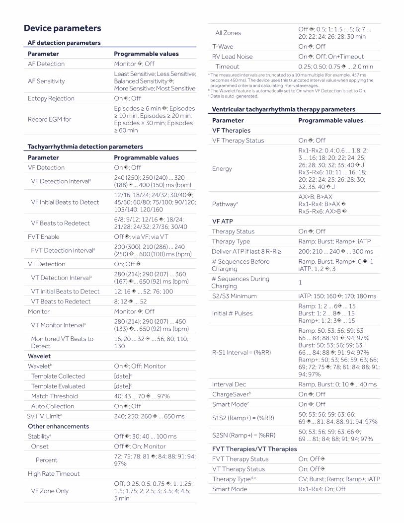
Device parameters
AF detection parameters
Parameter Programmable values
AF Detection Monitor ; Off
AF SensitivityLeast Sensitive; Less Sensitive; Balanced Sensitivity ; More Sensitive; Most Sensitive
Ectopy Rejection On ; Off
Record EGM for
Episodes ≥ 6 min ; Episodes ≥ 10 min; Episodes ≥ 20 min; Episodes ≥ 30 min; Episodes ≥ 60 min
Tachyarrhythmia detection parameters
Parameter Programmable values
VF Detection On ; Off
VF Detection Intervala 240 (250); 250 (240) … 320 (188) … 400 (150) ms (bpm)
VF Initial Beats to Detect12/16; 18/24; 24/32; 30/40 ; 45/60; 60/80; 75/100; 90/120; 105/140; 120/160
VF Beats to Redetect 6/8; 9/12; 12/16 ; 18/24; 21/28; 24/32; 27/36; 30/40
FVT Enable Off ; via VF; via VT
FVT Detection Intervala 200 (300); 210 (286) … 240 (250) … 600 (100) ms (bpm)
VT Detection On; Off
VT Detection Intervala 280 (214); 290 (207) … 360 (167) … 650 (92) ms (bpm)
VT Initial Beats to Detect 12; 16 … 52; 76; 100
VT Beats to Redetect 8; 12 … 52
Monitor Monitor ; Off
VT Monitor Intervala 280 (214); 290 (207) … 450 (133) … 650 (92) ms (bpm)
Monitored VT Beats to Detect
16; 20 … 32 … 56; 80; 110; 130
Wavelet
Waveletb On ; Off; Monitor
Template Collected [date]c
Template Evaluated [date]c
Match Threshold 40; 43 … 70 … 97%
Auto Collection On ; Off
SVT V. Limita 240; 250; 260 … 650 ms
Other enhancements
Stabilitya Off ; 30; 40 … 100 ms
Onset Off ; On; Monitor
Percent 72; 75; 78; 81 ; 84; 88; 91; 94; 97%
High Rate Timeout
VF Zone OnlyOff; 0.25; 0.5; 0.75 ; 1; 1.25; 1.5; 1.75; 2; 2.5; 3; 3.5; 4; 4.5; 5 min
All Zones Off ; 0.5; 1; 1.5 … 5; 6; 7 … 20; 22; 24; 26; 28; 30 min
T-Wave On ; Off
RV Lead Noise On ; Off; On+Timeout
Timeout 0.25; 0.50; 0.75 … 2.0 mina The measured intervals are truncated to a 10 ms multiple (for example, 457 ms
becomes 450 ms). The device uses this truncated interval value when applying the programmed criteria and calculating interval averages.
b The Wavelet feature is automatically set to On when VF Detection is set to On. c Date is auto-generated.
Ventricular tachyarrhythmia therapy parameters
Parameter Programmable values
VF Therapies
VF Therapy Status On ; Off
Energy
Rx1-Rx2: 0.4; 0.6 … 1.8; 2; 3 … 16; 18; 20; 22; 24; 25; 26; 28; 30; 32; 35; 40 JRx3-Rx6: 10; 11 … 16; 18; 20; 22; 24; 25; 26; 28; 30; 32; 35; 40 J
PathwayaAX>B; B>AXRx1-Rx4: B>AX Rx5-Rx6: AX>B
VF ATP
Therapy Status On ; Off
Therapy Type Ramp; Burst; Ramp+; iATP
Deliver ATP if last 8 R-R ≥ 200; 210 … 240 … 300 ms
# Sequences Before Charging
Ramp, Burst, Ramp+: 0 ; 1iATP: 1; 2 ; 3
# Sequences During Charging 1
S2/S3 Minimum iATP: 150; 160 ; 170; 180 ms
Initial # PulsesRamp: 1; 2 … 6 … 15Burst: 1; 2 … 8 … 15Ramp+: 1; 2; 3 … 15
R-S1 Interval = (%RR)
Ramp: 50; 53; 56; 59; 63; 66 … 84; 88; 91 ; 94; 97%Burst: 50; 53; 56; 59; 63; 66 … 84; 88 ; 91; 94; 97%Ramp+: 50; 53; 56; 59; 63; 66; 69; 72; 75 ; 78; 81; 84; 88; 91; 94; 97%
Interval Dec Ramp, Burst: 0; 10 … 40 ms
ChargeSaverb On ; Off
Smart Modec On ; Off
S1S2 (Ramp+) = (%RR) 50; 53; 56; 59; 63; 66; 69 … 81; 84; 88; 91; 94; 97%
S2SN (Ramp+) = (%RR) 50; 53; 56; 59; 63; 66 ; 69 … 81; 84; 88; 91; 94; 97%
FVT Therapies/VT Therapies
FVT Therapy Status On; Off
VT Therapy Status On; Off
Therapy Typed,e CV; Burst; Ramp; Ramp+; iATP
Smart Mode Rx1-Rx4: On; Off

Ventricular tachyarrhythmia therapy parameters, cont’d.
Parameter Programmable values
# Sequences
iATP:FVT therapies: 2; 3; 4; 5 … 10VT therapies: 2; 3 … 7 ; 8; 9; 10Burst, Ramp, Ramp+:VT therapies: 1; 2; 3 … 10FVT therapies: 1 ; 2 …10
S2/S3 Minimum iATP: 150; 160 ; 170; 180 ms
Initial # PulsesRamp: 1; 2 … 6 … 15Burst: 1; 2 … 8 … 15Ramp+: 1; 2; 3 … 15
R-S1 Interval = (%RR)
Burst: 50; 53; 56; 59; 63; 66 … 84; 88 ; 91; 94; 97%Ramp: 50; 53; 56; 59; 63; 66 … 84; 88; 91 ; 94; 97%Ramp+: 50; 53; 56; 59; 63; 66; 69; 72; 75 ; 78; 81; 84; 88; 91; 94; 97%
S1S2 (Ramp+) = (%RR) 50; 53; 56; 59; 63; 66; 69 … 81; 84; 88; 91; 94; 97%
S2SN (Ramp+) = (%RR) 0; 53; 56; 59; 63; 66 ; 69 … 81; 84; 88; 91; 94; 97%
Interval Dec Burst, Ramp: 0; 10 … 40 ms
CV for FVT and VT therapies
Energy
0.4; 0.6 … 1.8; 2; 3 … 16; 18; 20; 22; 24; 25; 26; 28; 30; 32; 35; 40 J VT Rx1-Rx2: 20 J VT Rx3-Rx6: 40 J FVT Rx1-Rx6: 40 J
PathwayaAX>B; B>AX Rx1-Rx4: B>AX Rx5-Rx6: AX>B
Shared V. ATP
V-V Minimum ATP Interval 150; 160 … 200 … 400 ms
V. Amplitude 1; 2; 3 … 6; 8 V
V. Pulse Width 0.1; 0.2 … 1.5 ms
V. Pace Blanking 170 ; 180; 190 … 450 ms
Shared V. Therapies
Active Can/SVC Coilf Can+SVC On ; Can Off; SVC Off
Progressive Episode Therapies On; Off
Confirmation+ On ; Offa If the Active Can/SVC Coil parameter is set to Can Off, the Active Can electrode is
not used as part of the high-voltage delivery pathway. If the Active Can/SVC Coil parameter is set to SVC Off, the SVC Coil electrode is not used as part of the high-voltage delivery pathway.
b ChargeSaver is not available for iATP. c Smart Mode is available for Rx1-Rx4.d FVT therapies must be increasingly aggressive.e Last therapy that is programmed to On must be a CV. f The Active Can/SVC Coil parameter applies to all automatic, manual, and emergency
high-voltage therapies. It also applies to T-Shock inductions.
Pacing parameters
Modes, rates, and intervals
Parameter Programmable values
Mode VVI ; VVIR; VOO; OVO
Lower Ratea 30; 35; 40 ... 60; 70; 75; 80 … 150 bpm
a The corresponding Lower Rate Interval can be calculated as follows: Lower Rate Interval (ms) = 60,000/Lower Rate.
RV pacing parameters
Parameter Programmable values
RV Amplitude0.50; 0.75 … 1.25; 1.50; 1.75 … 3.50 … 5.00; 5.50; 6.00; 8.00 V
RV Pulse Width 0.03; 0.06; 0.10; 0.20; 0.30; 0.40 … 1.50 ms
RV Sensitivitya 0.15; 0.30 ; 0.45; 0.60; 0.90; 1.20 mV
Pace Polarity Bipolar; Tip to Coil
Sense Polarity Bipolar; Tip to Coila This setting applies to all sensing in this chamber for both tachyarrhythmia detection
and bradycardia pacing operations.
RV Capture Management™ parameters
Parameter Programmable values
RV Capture Management Adaptive ; Monitor; Off
RV Amplitude Safety Margin 1.5x; 2.0x ; 2.5x; 3.0x
RV Minimum Adapted Amplitude 1.0; 1.5; 2.0 ; 2.5; 3.0; 3.5 V
RV Acute Phase Remaining Off; 30; 60; 90; 120 ; 150 days
Blanking periods
Parameter Programmable values
V. Blank Post VP 150; 160 … 200 … 450 ms
V. Blank Post VS 120 ; 130 … 170 ms
Rate Response pacing parameters
Parameter Programmable values
Upper Sensor Rate 80; 85 … 120 … 175 bpm
ADL Rate 60; 65 … 95 … 170 bpm
Rate Profile Optimization On ; Off
ADL Response 1; 2; 3 ; 4; 5
Exertion Response 1; 2; 3 ; 4; 5
Activity Threshold Low ; Medium Low;Medium High; High
Activity Acceleration 15; 30 ; 60 s
Activity Deceleration Exercise ; 2.5; 5; 10 min
ADL Setpoint 5; 6 … 40; 42 … 80
UR Setpoint 15; 16 … 40; 42 … 80; 85 … 180

Conducted AF response parameters
Parameter Programmable values
Conducted AF Response On; Off
Response Level Low; Medium ; High
Maximum Rate 80; 85 … 110 … 130 bpm
Ventricular rate stabilization parameters
Parameter Programmable values
V. Rate Stabilization On; Off
Maximum Rate 80; 85 … 100 … 120 bpm
Interval Increment 100; 110 … 150 … 400 ms
Post VT/VF shock pacing parameters
Parameter Programmable values
Post VT/VF Shock Pacing On; Off
Overdrive Rate 70; 75; 80 … 120 bpm
Overdrive Duration 0.5 ; 1; 2; 3; 5; 10; 20; 30; 60; 90; 120 min
Post shock pacing parameters
Parameter Programmable values
Post Shock V. Amplitude 1; 2 … 6 ; 8 V
Post Shock V. Pulse Width 0.1; 0.2 … 1.5 (± 0.025 ms)
Sleep parameters
Parameter Programmable values
Sleep On; Off
Sleep Rate 30; 35 … 50 ; 55; 60; 70; 75 … 100 bpm
Bed Time 00:00; 00:10 … 22:00 … 23:50
Wake Time 00:00; 00:10 … 07:00 … 23:50
MRI SureScan parameters
Parameter Programmable values
MRI SureScan On; Off
MRI Pacing Mode VOO (Asynchronous); OVO (Off)
MRI Pacing Rate 60; 70; 75 … 120 bpm
Additional pacing features
Parameter Programmable values
Rate Hysteresis Off ; 30; 40 … 80 bpm
Medtronic CareAlert™ parameters
Clinical management alerts
Parameter Programmable values
OptiVol 2.0 Fluid Settings
Device Tone and Wireless Alert
OptiVol Alert enable
Device ToneOff ; On; Suspend 3 days; Suspend 5 days; Suspend 7 days; Suspend 14 days
Wireless Alert Off ; On
OptiVol Thresholdb 30; 40: 50; 60 … 180
AF Burden and Rate Settings
Device Tone and Wireless Alert
AF Daily Burden Off ; On
Daily AF Burden 0.5; 1; 2; 6 ; 12; 24 h
Avg. V. Rate during AF Off ; On
Avg. V. Rate during AT/AF Burden Time 0.5; 1; 2; 6 ; 12; 24 h
Avg. V. Rate during AF 90; 100 … 150 bpm
VT/VF Episodes and Therapies
Device Tone and Wireless Alert
Monitored VT Episode Detected Off ; On
Thresholds 1 episode
Daily VT/VF Episodes Off ; On
Thresholds 3 episodes/day
Weekly ATP Delivered Episodes Off ; On
Thresholds 1 ; 2; 3; 4; 5
Number of Shocks Delivered in an Episoded Off ; On
Thresholdsc 1 ; 2; 3; 4; 5; 6
Cumulative Right Ventricular Pacing > 40%
Device Tone and Wireless Alert Off ; Ona
a Alert triggered if percent of cumulative right ventricular pacing is greater than 40% for 7 consecutive days.
b Decreasing the OptiVol Threshold makes the device more sensitive to changes in the patient’s thoracic fluid status. Increasing the OptiVol Threshold could delay or prevent device observation of significant changes in the patient’s thoracic fluid status.
c This parameter is displayed only if an associated alert has been enabled. d Note that VF, VT, and FVT therapies could be delivered during a single episode (from
initial detection until episode termination).

Lead/device integrity alerts
Parameter Programmable values
RV Lead
Device Tone and Wireless Alert
RV Lead Integrity On ; Off
RV Lead Noise On ; Off
Lead Impedance Out of Range
Device Tone and Wireless Alert
RV Pacing Enable On ; Off
RV Pacing Less than 200 ; 300; 400; 500 Ω
RV Pacing Greater than 1,000; 1,500; 2,000; 3,000 Ω
RV Defibrillation Enablec On ; Off
RV Defibrillation Less than 20 ; 30; 40; 50 Ω
RV Defibrillation Greater than 100; 130; 160; 200 Ω
SVC Defibrillation Enablea On ; Off
SVC Defibrillation Less than 20 ; 30; 40; 50 Ω
SVC Defibrillation Greater than 100; 130; 160; 200 Ω
Capture Management High Threshold
Device Tone and Wireless Alert
RV Capture Off ; On
Low Battery Voltage RRT
Device Tone and Wireless Alert On ; Off
Excessive Charge Time EOS
Device Tone and Wireless Alert On ; Off
VF Detection Off, 3+ VF or 3+ FVT Rx Off
Device Tone and Wireless Alert On ; Off
a If an SVC lead is not implanted, the alert will not sound.
Shared parameters
Parameter Programmable values
Wireless Telemetry with Monitor
On ; Off
Alert Time (OptiVol)a 00:00; 00:10 … 10:10 … 23:50b
Alert Time (all others)a 00:00; 00:10 … 08:00 … 23:50b
a This parameter is displayed only if an associated alert has been enabled.b The implantable device app expresses time in the 24-hour format or in the 12-hour
format, depending on your tablet settings.
Data collection parameters
Data collection parameters
Parameter Programmable values
LECG Sourcea Can to SVC; Can to RVcoil ; RVcoil to SVC
LECG Range ±1; ±2 ; ±4; ±8; ±12; ±16; ±32 mV
EGM 1 Source RVtip to RVcoil; RVtip to RVring
EGM 1 Range ±1; ±2; ±4; ±8 ; ±12; ±16; ±32 mV
EGM 2 (Wavelet) Source
Can to RVcoil ; Can to RVring; RVtip to RVcoil; RVtip to RVring; Can to SVCb,c; RVcoil to SVCb
EGM 2 (Wavelet) Range ±1; ±2; ±4; ±8; ±12 ; ±16; ±32 mV
EGM 3 Source RVtip to RVcoil ; RVtip to RVring; Can to RVcoil
EGM 3 Range ±1; ±2; ±4; ±8 ; ±12; ±16; ±32 mV
Stored (Ventricular)
EGM1 and EGM2 ; EGM1 and EGM3; EGM2 and EGM3; EGM1 and LECG; EGM2 and LECG; EGM3 and LECG
Stored (Atrial) EGM1 and LECG; EGM2 and LECG ; EGM3 and LECG
Pre-arrhythmia EGM Off; On – 1 month; On – 3 months ; On Continuous
Device Date/Timed (select Time Zone)
Holter Telemetry Duration Off ; 0.5; 1; 2; 4; 8; 16; 24; 36; 46 h
a This EGM channel displays far-field signals. b An SVC electrode must be present for this configuration.c If Can to SVC is selected, the EGM Range is automatically set to ± 2 mV. The EGM
Range is automatically set to ± 8 mV for all other EGM Source options.d The times and dates stored in episode records and other data are determined by the
Device Date/Time clock.
System test parameters
System test parameters
Parameter Selectable values
Pacing Threshold Test parameters
Test Type Amplitude ; Pulse Width
Chamber RV
Decrement after 2; 3 … 15 pulses
RV Pace Polarity Bipolar; Tip to Coil
Modea VVI; VOO
Lower Rate 30; 35 … 60; 70; 75 … 150 bpm
RV Amplitude 0.25; 0.5 … 5; 5.5; 6; 8 V
RV Pulse Width 0.03; 0.06; 0.1; 0.2 … 1.5 ms
Additional Settings

V. Pace Blanking 150; 160 … 450 ms
System test parameters, cont’d.
Parameter Selectable values
Sensing Test parameters
Modea VVI; OVO
Lower Rate 30; 35 … 60; 70; 75 … 120 bpm
Wavelet Test parameters
Permanent Valuesb
Wavelet On; Off; Monitor
Match Threshold 40; 43 … 70 … 97%
Auto Collection On ; Off
Temporary Values
Modea OVO; VVI
Lower Rate 30; 35 … 60; 70; 75 … 120 bpma The selectable values for this parameter depend on the programmed pacing mode.b Tap ADJUST PERMANENT to change the values for these parameters.
EP study parameters
T-Shock induction parameters
Parameter Selectable values
Resume at Deliver Enabled ; Disabled
Enable Enabled; Disabled
Chamber RV
#S1 2; 3; 4; 5 ; 6; 7; 8
S1S1 300; 310 … 400 … 2,000 ms
Delay 20; 30 … 300 … 600 ms
Energy/Pathway
Energy0.4; 0.6; 0.8; 1.0 … 1.8; 2; 3; 4 … 16; 18; 20; 22; 24; 25; 26; 28; 30; 32; 35; 40 J
Pathwaya AX>B; B>AX
Waveform Monophasic ; Biphasica If the Active Can/SVC Coil parameter is set to Can Off, the Active Can electrode is not
used as part of the high-voltage delivery pathway. If the Active Can/SVC Coil parameter is set to SVC Off, the SVC Coil electrode is not used as part of the high-voltage delivery pathway.
50 Hz Burst induction parameters
Parameter Selectable values
Resume at Burst Enabled ; Disabled
Amplitude 1; 2; 3; 4 ; 5; 6; 8 V
Pulse Width 0.10; 0.20 … 0.50 … 1.50 ms
Fixed Burst induction parameters
Parameter Selectable values
Resume at Burst Enabled ; Disabled
Interval 100; 110 … 600 ms
Amplitude 1; 2; 3; 4 ; 5; 6; 8 V
Pulse Width 0.10; 0.20 … 0.50 … 1.50 ms
PES induction parameters
Parameter Selectable values
Resume at Deliver Enabled ; Disabled
Chamber RV
#S1 1; 2 … 8 … 15
S1S1 100; 110 … 600 … 2,000 ms
S1S2 On; Off; 100; 110 … 400 … 600 ms
S2S3 On; Off ; 100; 110 … 600 msa
S3S4 On; Off ; 100; 110 … 600 msa
Amplitude 1; 2; 3; 4 ; 5; 6; 8 V
Pulse Width 0.10; 0.20 … 0.50 … 1.50 msa Default value when parameter is On is 400 ms.
Defibrillation parameters
Parameter Selectable values
Chamber RV
Energy0.4; 0.6 … 1.8; 2; 3 … 16; 18; 20; 22; 24; 25; 26; 28; 30; 32; 35; 40 J
Pathwaya AX>B; B>AX a If the Active Can/SVC Coil parameter is set to Can Off, the Active Can electrode is not
used as part of the high-voltage delivery pathway. If the Active Can/SVC Coil parameter is set to SVC Off, the SVC Coil electrode is not used as part of the high-voltage delivery pathway.
Cardioversion parameters
Parameter Selectable values
Chamber RV
Energy0.4; 0.6 … 1.8; 2; 3 … 16; 18; 20; 22; 24; 25; 26; 28; 30; 32; 35; 40 J
Pathwaya AX>B; B>AX a If the Active Can/SVC Coil parameter is set to Can Off, the Active Can electrode is not
used as part of the high-voltage delivery pathway. If the Active Can/SVC Coil parameter is set to SVC Off, the SVC Coil electrode is not used as part of the high-voltage delivery pathway.
Shared ATP therapy parameters
Parameter Selectable values
Minimum Interval 150; 160 … 200 … 400 ms
Amplitude 1; 2 … 6 ; 8 V
Pulse Width 0.10; 0.20 … 1.50 ms
Ramp parameters
Parameter Selectable values
Chamber RVa
# Pulses 1; 2 … 6 … 15
%RR Interval 50; 53; 56; 59; 63; 66 … 84; 88; 91; 94; 97 %
Dec/Pulse 0; 10 ; 20; 30; 40 msa This value is nonprogrammable.

Longevity
Projected service life in years
RV amplitude/pace % Projected service life per impedance
500 Ω RV 437 Ω
2.0 V, 0% 13.6 yearsa 13.6 yearsb
2.0 V, 100% 11.9 yearsa
2.5 V, 100% 11.2 yearsa Per EN 45502-2-2 or ISO 14708-6 for paced percentage and lead impedance. b Based on median CareLink™ settings for amplitude, paced percentage, and lead impedance.
The service life projections are based on the following assumptions:§ Semi-annual maximum energy charging frequency§ A quarterly schedule of remote telemetry transmissions§ Typical shelf storage time before implant§ 1 hour of wireless telemetry during implant§ 1 hour of in-office wireless telemetry annually
Projected service life estimates are based on accelerated battery discharge data and device modeling as specified. Do not interpret these values as precise numbers.
Burst parameters
Parameter Selectable values
Chamber RVa
# Pulses 1; 2 … 8 … 15
%RR Interval 50; 53; 56; 59; 63; 66 … 84; 88 ; 91; 94; 97%
a This value is nonprogrammable.
Ramp+ parameters
Parameter Selectable values
Chamber RVa
# Pulses 1; 2; 3 … 15
R-S1 (%RR) 50; 53; 56; 59; 63; 66 … 75 … 84; 88; 91; 94; 97%
S1S2 (%RR) 50; 53; 56; 59; 63; 66; 69 … 84; 88; 91; 94; 97%
S2SN (%RR) 50; 53; 56; 59; 63; 66 … 84; 88; 91; 94; 97%
a This value is nonprogrammable.

Brief Statement: Cobalt™/Crome™ MRI SureScan™ ICD and CRT-D Systems Indications: The Cobalt™ XT, Cobalt™, and Crome™ HF CRT-D MRI SureScan™ systems are indicated for use in patients who are at significant risk of developing atrial and/or life-threatening ventricular arrhythmias and who have heart failure with ventricular arrhythmias. Heart failure patients must have experienced one or more of the following conditions:§ NYHA Functional Class III or IV patients who remain symptomatic despite
stable, optimal medical therapy and have LVEF ≤ 35% and a prolonged QRS duration§ NYHA Functional Class II patients who have left bundle-branch block (LBBB)
with a QRS duration ≥ 130 ms and a left ventricular ejection fraction ≤ 30%§ NYHA Functional Class I, II, or III who are on stable, optimal medical therapy
(if indicated), and have LVEF ≤ 50%, atrioventricular block (AV block), and are expected to require a high percentage of ventricular pacing that cannot be managed with algorithms to minimize right ventricular pacing
The Cobalt XT, Cobalt, and Crome VR and DR ICD MRI SureScan systems are indicated for the automated treatment of patients who have experienced, or are at significant risk of developing, atrial and/or life-threatening ventricular arrhythmias through the delivery of antitachycardia pacing, cardioversion, and defibrillation therapies. MRI Conditions for Use: Medtronic SureScan ICD and CRT-D systems are MR Conditional, and as such are designed to allow patients to undergo MRI under the specified conditions for use. ICD and CRT-D SureScan system patients may be scanned using a horizontal field, cylindrical bore, clinical 1.5T or 3T MRI system for hydrogen proton imaging. When programmed to On, the MRI SureScan feature allows the patient to be safely scanned while the device continues to provide appropriate pacing. A complete SureScan defibrillation system, which is a SureScan device with appropriate SureScan lead(s), is required for use in the MR environment. To verify that components are part of a SureScan system, visit http://www.mrisurescan.com/. Any other combination may result in a hazard to the patient during an MRI scan.
Contraindications: The Cobalt XT, Cobalt, and Crome VR and DR ICD and CRT-D MRI SureScan systems are contraindicated for use in the following situations:§ If implanted with a unipolar pacemaker§ If incessant VT or VF exists§ If the primary disorder is chronic atrial tachyarrhythmia with no concomitant VT or VF§ If tachyarrhythmias with transient or reversible causes exist, including the
following known issues: acute myocardial infarction, drug intoxication, drowning, electric shock, electrolyte imbalance, hypoxia, and sepsis.
Warnings and Precautions: Changes in a patient’s disease and/or medications may alter the efficacy of the device’s programmed parameters. Patients should avoid sources of magnetic and electromagnetic radiation to avoid possible underdetection, inappropriate sensing and/or therapy delivery, tissue damage, induction of an arrhythmia, device electrical reset, or device damage. Do not place transthoracic defibrillation paddles directly over the device.Patients and their implanted systems must be screened to meet the following requirements for MRI: no lead extenders, lead adaptors, or abandoned leads present; no broken leads or leads with intermittent electrical contact as confirmed by lead impedance history. The device must be operating within the projected service life, and the system must be implanted in the left or right pectoral region. Potential Adverse Events: Potential adverse events include, but are not limited to, the following events: allergic reactions, atrial fibrillation, bradyarrhythmia, cardiac arrest, device migration, discomfort, dizziness, dyspnea, erosion, excessive fibrotic tissue growth, heart failure or loss of CRT (for CRT-D patients), hematoma, hemorrhage, inability to deliver therapy, inappropriate shock, infection, lead migration/dislodgement, lethargy, loss of pacing, mental anguish, necrosis, nerve damage, oversensing, palpitations, seroma, syncope, tachyarrhythmia, tissue damage due to heating of the device, undersensing, and wound dehiscence.Potential MRI complications include, but are not limited to, lead electrode heating and tissue damage resulting in loss of sensing or capture or both, spontaneous tachyarrhythmia, potential for VT/VF induction, device heating that results in tissue damage, stimulation of the leads that results in continuous capture, VT/VF, hemodynamic collapse, damage to the device or the leads, causing the system to fail or treat the patient’s condition incorrectly, and movement or vibration of the device or the leads, resulting in dislodgment.See the device manuals for detailed information regarding the implant procedure, indications, contraindications, warnings, precautions, and adverse events. See the MRI SureScan Technical Manual before performing an MRI Scan. For further information, call Medtronic at 1-800-328-2518 and/or consult the Medtronic website at medtronic.com or mrisurescan.com. Caution: Federal law (USA) restricts these devices to sale by or on the order of a physician.
Medtronic and the Medtronic logo are trademarks of Medtronic. ™Third party brands are trademarks of their respective owners. All other brands are trademarks of a Medtronic company.
medtronic.comUC202001369 EN ©2020 Medtronic. Minneapolis, MN. All Rights Reserved. Printed in USA. 08/2020
Medtronic 710 Medtronic Parkway Minneapolis, MN 55432-5604 USA
Toll-free in USA: 800.633.8766Worldwide: +1.763.514.4000