Embed Size (px)
Citation preview

COAST SPASTSPA-MP SERVICE MANUAL
• Gecko Electronics Inc. •
Visual step-by-step guide to easily
identify & correct technical problems!
Table of Contents
Power & Ground CheckElectrical Wiring 4GFCI 5
Error ConditionsService Icon Appearing on Keypad Display 9Service Icon and LED Displayed 13Display is Flashing 17Wrong Temperature Appearing on Keypad Display 20Smart Winter Mode 23
MiscellaneousWiring Diagram 67Professional Repair Kit Info 68
Note: For spa repairs and troubleshooting with Pocket-tek technology please refer to Pocket-tek User's Manual available from Gecko and at www.pocket-tek.com.
How to ...Replace The Board 59Replace The Heater 63Adjust The Pressure Switch 65
TroubleshootingNothing Seems to Work! 25Spa Does Not Heat! 29Pump 1/Pump 2 Do Not Work! 33Blower Does Not Work! 39Light Does Not Work! 43Fiber Box Light Does Not Work! 45Ozonator Does Not Work! 47Circulation Pump Does Not Work! 49Keys Do Not Work! 51TV Lifter Does Not Work! 53TV Does Not Work! 55VCR-DVD/CD-Radio Do Not Work! 57
ProgrammingLow Level Programming 8

In an attempt to make this manual as useful as possible, it has been presented in two formats. Problem-solving solutions are described with Troubleshooting Flow Charts and also with Step-by-Step Procedures.
The two formats together should provide an overall complete explanation, with flow charts providing an overview of specific problems, and step-by-step procedures giving more detailed information.
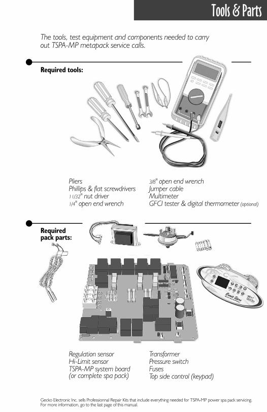
Tools & Parts
The tools, test equipment and components needed to carry out TSPA-MP metapack service calls.
Required tools:
Required pack parts:
Gecko Electronic Inc. sells Professionnal Repair Kits that include everything needed for TSPA-MP power spa pack servicing. For more information, go to the last page of this manual.
PliersPhillips & flat screwdrivers11/32" nut driver1/4" open end wrench
3/8" open end wrenchJumper cableMultimeterGFCI tester & digital thermometer (optional)
Regulation sensorHi-Limit sensorTSPA-MP system board(or complete spa pack)
TransformerPressure switchFusesTop side control (keypad)
4 TSPA-MP Metapacks Service Manual
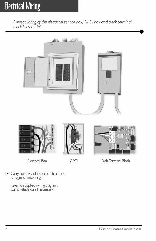
Electrical Wiring
Correct wiring of the electrical service box, GFCI box and pack terminal block is essential.
1• Carry out a visual inspection to check for signs of miswiring.
Refer to supplied wiring diagrams. Call an electrician if necessary.
Electrical Box GFCI Pack Terminal Block
5TSPA-MP Metapacks Service Manual
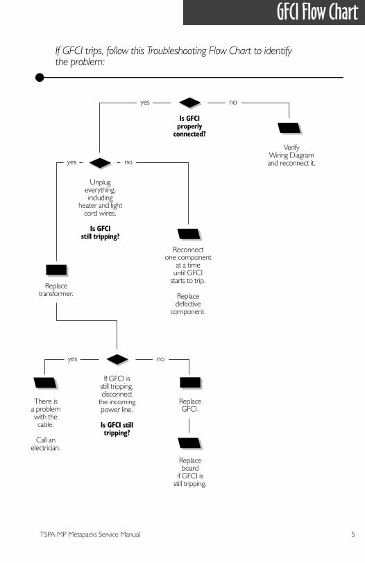
If GFCI trips, follow this Troubleshooting Flow Chart to identifythe problem:
GFCI Flow Chart
Is GFCIproperly
connected?
If GFCI isstill tripping,disconnect
the incomingpower line.
Is GFCI stilltripping?
ReplaceGFCI.
Replaceboard
if GFCI isstill tripping.
There isa problemwith thecable.
Call anelectrician.
Unplugeverything,including
heater and lightcord wires.
Is GFCIstill tripping?
Replacetransformer.
Reconnectone component
at a timeuntil GFCI
starts to trip.
Replacedefective
component.
VerifyWiring Diagramand reconnect it.
yes
yes no
no
yes no
6 TSPA-MP Metapacks Service Manual
GFCI Trips!
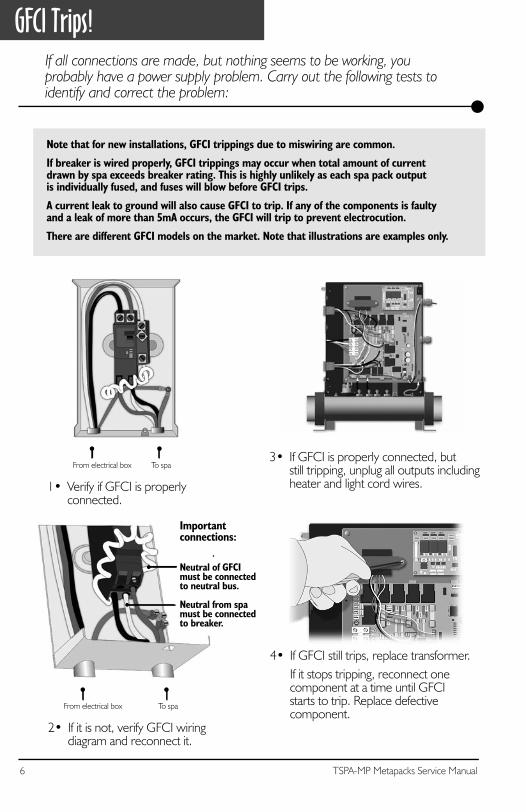
4• If GFCI still trips, replace transformer.If it stops tripping, reconnect one component at a time until GFCI starts to trip. Replace defectivecomponent.
1• Verify if GFCI is properlyconnected.
3• If GFCI is properly connected, butstill tripping, unplug all outputs includingheater and light cord wires.
If all connections are made, but nothing seems to be working, you probably have a power supply problem. Carry out the following tests to identify and correct the problem:
Note that for new installations, GFCI trippings due to miswiring are common.
If breaker is wired properly, GFCI trippings may occur when total amount of current drawn by spa exceeds breaker rating. This is highly unlikely as each spa pack outputis individually fused, and fuses will blow before GFCI trips.
A current leak to ground will also cause GFCI to trip. If any of the components is faultyand a leak of more than 5mA occurs, the GFCI will trip to prevent electrocution.
There are different GFCI models on the market. Note that illustrations are examples only.
From electrical box To spa
2• If it is not, verify GFCI wiring diagram and reconnect it.
From electrical box To spa
Important connections:
Neutral of GFCImust be connected to neutral bus.
Neutral from spamust be connected to breaker.
7TSPA-MP Metapacks Service Manual
GFCI Trips!
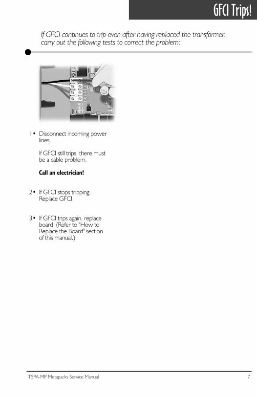
1• Disconnect incoming powerlines.
If GFCI still trips, there mustbe a cable problem.
Call an electrician!
2• If GFCI stops tripping. Replace GFCI.
3• If GFCI trips again, replaceboard. (Refer to "How toReplace the Board" sectionof this manual.)
If GFCI continues to trip even after having replaced the transformer,carry out the following tests to correct the problem:
8 TSPA-MP Metapacks Service Manual
Low Level Programming
Certain system operating parameters can be configured from the keypad. This is normally done by Gecko or the spa installer, but may be done any time.
5- OzoneDisplay: O3 xValue of x: 0 = not installed
1 = on only in filter cycle2 = always on
6- Circulation pumpDisplay: CP xValue of x: 0 = not installed
1 = regulated (with spatemperature)
2 = always on
7- Service messageDisplay: SEr xValue of x: 0 = message not displayed
1 = message displayed every 8000 hours
8- Current limiting optionDisplay: Cu xValue of x: 0 = low current (heater off
if more than one pumpis on at high speed)
1 = high current (no restrictions)
Low level programming:
To access low level programming, press and hold Program key for 20 seconds, after which the first parameter code should appear on the display.
Use Up/Down keys to modify parameter values and Program key to change fromone parameter to the next. You must go through all parameters to exit this mode. Ifyou do not wish to change a parameter, simply press Program key to advance to thenext parameter.
List of parameter configurations
1- Pump 1Display: P1 xValue of x: 1 = single-speed
2 = two-speed
2- Pump 2Display: P2 xValue of x: 0 = not installed
1 = single-speed2 = two-speed
3- BlowerDisplay: bL xValue of x: 0 = not installed
1 = single-speed2 = two-speed3 = three-speed
4- Light Display: LI xValue of x: 0 = not installed
1 = 12 VAC (single-intensity)2 = 12 VAC (triple-intensity)3 = 120 VAC (auxiliary 1
relay )4 = Internal fiber box control
mode (aux. 1 & 2 relays)
9TSPA-MP Metapacks Service Manual
Service Icon Flow Chart
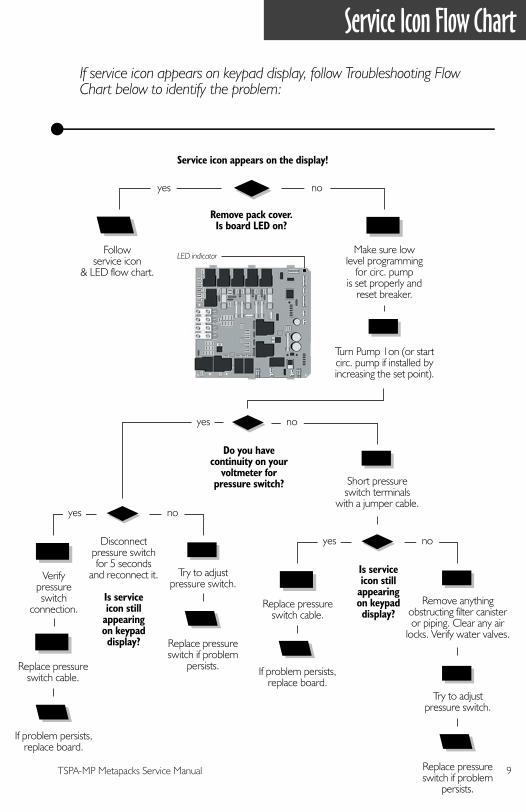
If service icon appears on keypad display, follow Troubleshooting Flow Chart below to identify the problem:
Service icon appears on the display!
Remove pack cover.Is board LED on?
Followservice icon
& LED flow chart.
yes no
Make sure lowlevel programming
for circ. pumpis set properly and
reset breaker.
Turn Pump 1on (or startcirc. pump if installed byincreasing the set point).
Do you havecontinuity on your
voltmeter forpressure switch?
yes no
Short pressureswitch terminals
with a jumper cable.
Replace pressureswitch cable.
Replace pressureswitch cable.
Remove anythingobstructing filter canisteror piping. Clear any air
locks. Verify water valves.
Try to adjustpressure switch.
Is serviceicon still
appearingon keypaddisplay?
If problem persists,replace board.
yes no
Replace pressureswitch if problem
persists.
Verifypressureswitch
connection.
Try to adjustpressure switch.
Disconnectpressure switchfor 5 seconds
and reconnect it.
Is serviceicon still
appearingon keypaddisplay?
If problem persists,replace board.
yes no
Replace pressureswitch if problem
persists.
LED indicator
10 TSPA-MP Metapacks Service Manual
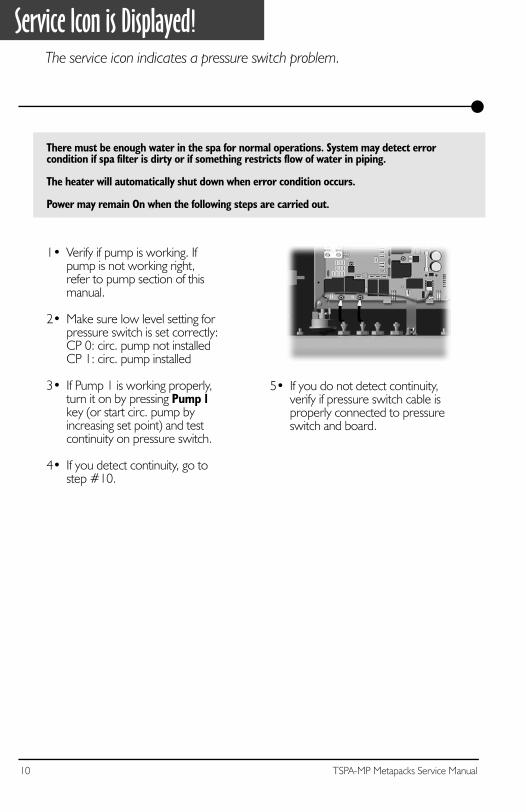
Service Icon is Displayed!The service icon indicates a pressure switch problem.
There must be enough water in the spa for normal operations. System may detect errorcondition if spa filter is dirty or if something restricts flow of water in piping.
The heater will automatically shut down when error condition occurs.
Power may remain On when the following steps are carried out.
5• If you do not detect continuity,verify if pressure switch cable isproperly connected to pressureswitch and board.
1• Verify if pump is working. Ifpump is not working right,refer to pump section of thismanual.
2• Make sure low level setting forpressure switch is set correctly:CP 0: circ. pump not installedCP 1: circ. pump installed
3• If Pump 1 is working properly,turn it on by pressing Pump 1key (or start circ. pump byincreasing set point) and testcontinuity on pressure switch.
4• If you detect continuity, go tostep #10.
11TSPA-MP Metapacks Service Manual
Service Icon is Displayed!
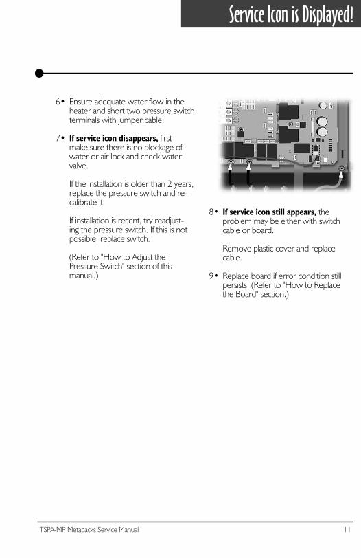
6• Ensure adequate water flow in theheater and short two pressure switchterminals with jumper cable.
7• If service icon disappears, firstmake sure there is no blockage ofwater or air lock and check watervalve.
If the installation is older than 2 years,replace the pressure switch and re-calibrate it.
If installation is recent, try readjust-ing the pressure switch. If this is notpossible, replace switch.
(Refer to "How to Adjust thePressure Switch" section of thismanual.)
8• If service icon still appears, theproblem may be either with switchcable or board.
Remove plastic cover and replacecable.
9• Replace board if error condition stillpersists. (Refer to "How to Replacethe Board" section.)
12 TSPA-MP Metapacks Service Manual
Service Icon is Displayed!
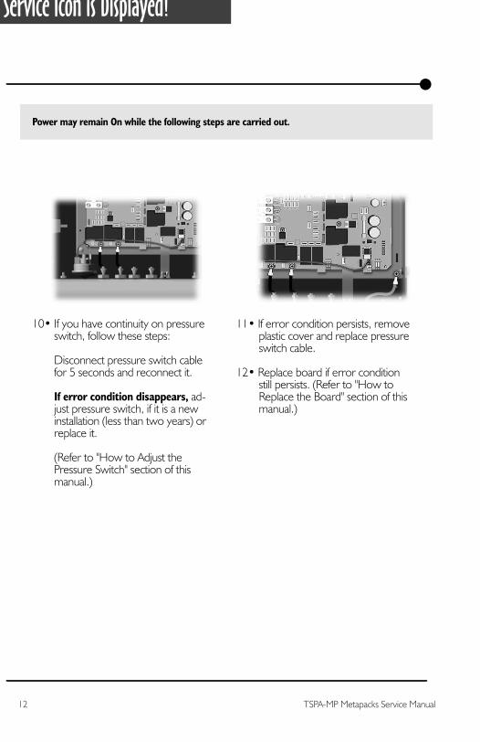
Power may remain On while the following steps are carried out.
11• If error condition persists, removeplastic cover and replace pressureswitch cable.
12• Replace board if error conditionstill persists. (Refer to "How toReplace the Board" section of thismanual.)
10• If you have continuity on pressureswitch, follow these steps:
Disconnect pressure switch cablefor 5 seconds and reconnect it.
If error condition disappears, ad-just pressure switch, if it is a newinstallation (less than two years) orreplace it.
(Refer to "How to Adjust thePressure Switch" section of thismanual.)
13TSPA-MP Metapacks Service Manual
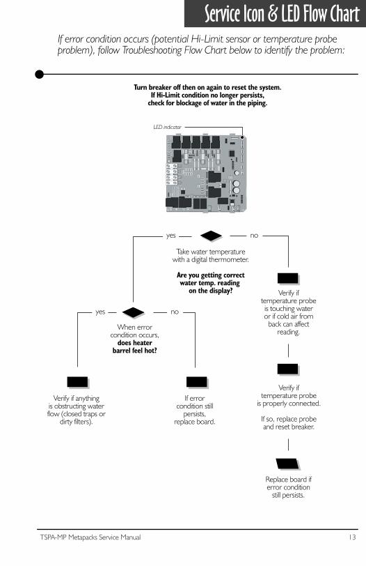
Service Icon & LED Flow Chart
Take water temperaturewith a digital thermometer.
Are you getting correctwater temp. reading
on the display?
yes no
Replace board iferror condition
still persists.
Verify iftemperature probe
is properly connected.
If so, replace probeand reset breaker.
Verify iftemperature probeis touching wateror if cold air from
back can affectreading.
If errorcondition still
persists,replace board.
Verify if anythingis obstructing waterflow (closed traps or
dirty filters).
When errorcondition occurs,
does heaterbarrel feel hot?
yes no
Turn breaker off then on again to reset the system.If Hi-Limit condition no longer persists,
check for blockage of water in the piping.
If error condition occurs (potential Hi-Limit sensor or temperature probe problem), follow Troubleshooting Flow Chart below to identify the problem:
LED indicator
14 TSPA-MP Metapacks Service Manual
Service Icon & LED Displayed
Turn breaker off then on again to reset the system.If service icon and LED disappear, wait until they are displayed again on keypad.Power may remain On.
1• Take water temperature withdigital thermometer.
2• If keypad display shows correcttemperature:
a- Check if heater barrel feels hot.
If it's hot, verify if anything is obstructing the flow of water(closed valves or dirty filter).
b- If heater barrel feels cold, re-place board. (Refer to "Howto Replace Board" section ofpresent manual.)
3• Proceed to following page ifkeypad display shows incorrecttemperature.
The service icon and LED error condition is related to the Hi-Limit sensor or temperature probe.
15TSPA-MP Metapacks Service Manual
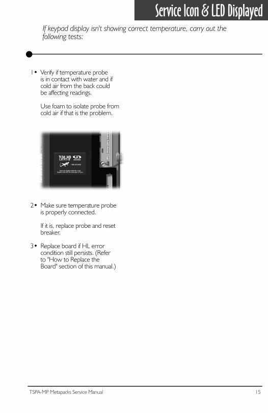
Service Icon & LED DisplayedIf keypad display isn't showing correct temperature, carry out thefollowing tests:
2• Make sure temperature probeis properly connected.
If it is, replace probe and resetbreaker.
3• Replace board if HL errorcondition still persists. (Referto "How to Replace theBoard" section of this manual.)
1• Verify if temperature probeis in contact with water and ifcold air from the back couldbe affecting readings.
Use foam to isolate probe fromcold air if that is the problem.

16 TSPA-MP Metapacks Service Manual
17TSPA-MP Metapacks Service Manual
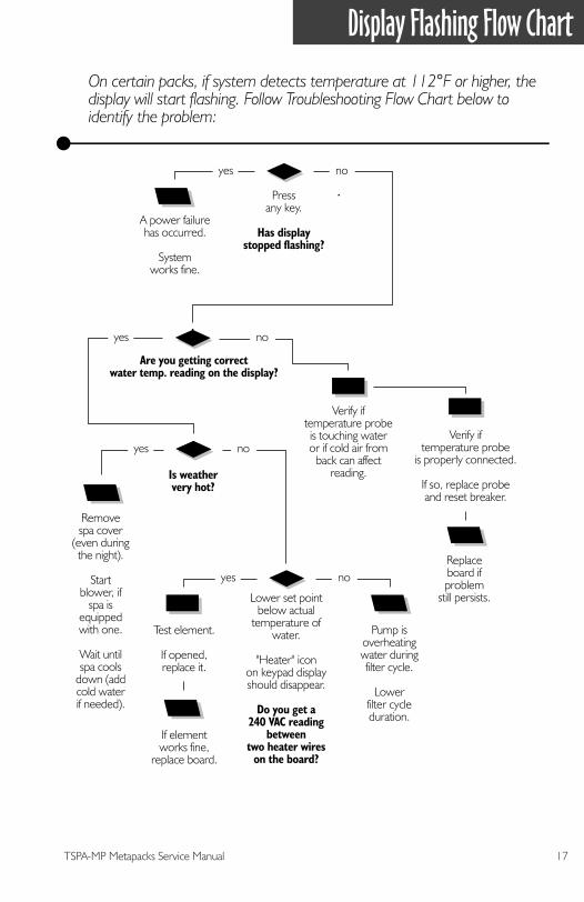
Display Flashing Flow Chart
On certain packs, if system detects temperature at 112°F or higher, the display will start flashing. Follow Troubleshooting Flow Chart below to identify the problem:
Are you getting correctwater temp. reading on the display?
Replaceboard ifproblem
still persists.
Verify iftemperature probe
is properly connected.
If so, replace probeand reset breaker.
Verify iftemperature probeis touching wateror if cold air from
back can affectreading.
Removespa cover
(even duringthe night).
Startblower, if
spa isequippedwith one.
Wait untilspa cools
down (addcold waterif needed).
Pump isoverheatingwater duringfilter cycle.
Lowerfilter cycleduration.
If elementworks fine,
replace board.
Lower set pointbelow actual
temperature ofwater.
"Heater" iconon keypad displayshould disappear.
Do you get a240 VAC reading
betweentwo heater wires
on the board?
yes no
Is weathervery hot?
yes no
Test element.
If opened,replace it.
yes no
A power failurehas occurred.
Systemworks fine.
Pressany key.
Has displaystopped flashing?
yes no
18 TSPA-MP Metapacks Service Manual
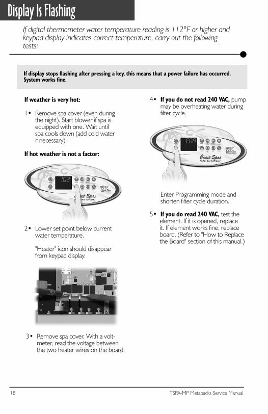
Display Is FlashingIf digital thermometer water temperature reading is 112°F or higher and keypad display indicates correct temperature, carry out the following tests:
If display stops flashing after pressing a key, this means that a power failure has occurred.System works fine.
If weather is very hot:
1• Remove spa cover (even duringthe night). Start blower if spa isequipped with one. Wait untilspa cools down (add cold waterif necessary).
If hot weather is not a factor:
2• Lower set point below currentwater temperature.
"Heater" icon should disappearfrom keypad display.
3• Remove spa cover. With a volt-meter, read the voltage betweenthe two heater wires on the board.
5• If you do read 240 VAC, test theelement. If it is opened, replaceit. If element works fine, replaceboard. (Refer to "How to Replacethe Board" section of this manual.)
4• If you do not read 240 VAC, pumpmay be overheating water duringfilter cycle.
Enter Programming mode andshorten filter cycle duration.
19TSPA-MP Metapacks Service Manual
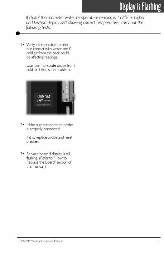
Display is FlashingIf digital thermometer water temperature reading is 112°F or higherand keypad display isn't showing correct temperature, carry out thefollowing tests:
2• Make sure temperature probeis properly connected.
If it is, replace probe and resetbreaker.
3• Replace board if display is stillflashing. (Refer to "How toReplace the Board" section ofthis manual.)
1• Verify if temperature probeis in contact with water and ifcold air from the back couldbe affecting readings.
Use foam to isolate probe fromcold air if that is the problem.

20 TSPA-MP Metapacks Service Manual
21TSPA-MP Metapacks Service Manual
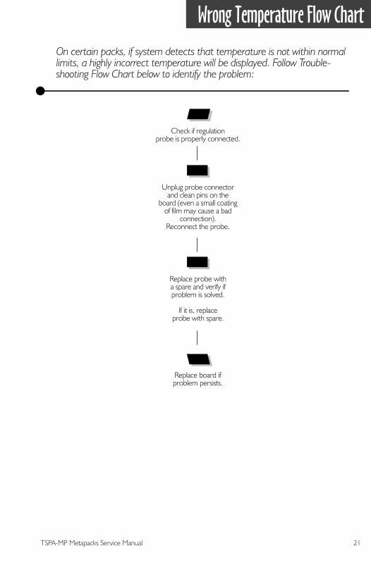
Wrong Temperature Flow Chart
On certain packs, if system detects that temperature is not within normal limits, a highly incorrect temperature will be displayed. Follow Trouble-shooting Flow Chart below to identify the problem:
Replace board ifproblem persists.
Check if regulationprobe is properly connected.
Replace probe witha spare and verify ifproblem is solved.
If it is, replaceprobe with spare.
Unplug probe connectorand clean pins on the
board (even a small coatingof film may cause a bad
connection).Reconnect the probe.
22 TSPA-MP Metapacks Service Manual
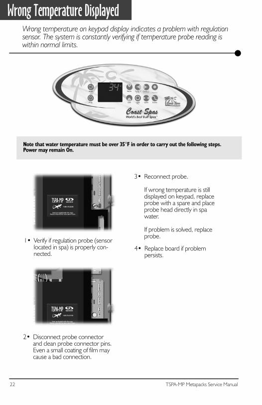
Wrong Temperature DisplayedWrong temperature on keypad display indicates a problem with regulation sensor. The system is constantly verifying if temperature probe reading is within normal limits.
Note that water temperature must be over 35°F in order to carry out the following steps.Power may remain On.
2• Disconnect probe connectorand clean probe connector pins.Even a small coating of film maycause a bad connection.
1• Verify if regulation probe (sensorlocated in spa) is properly con-nected.
4• Replace board if problempersists.
3• Reconnect probe.
If wrong temperature is stilldisplayed on keypad, replaceprobe with a spare and placeprobe head directly in spawater.
If problem is solved, replaceprobe.
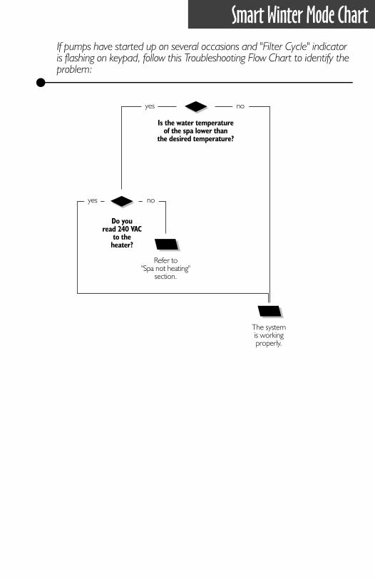
Smart Winter Mode Chart
If pumps have started up on several occasions and "Filter Cycle" indicator is flashing on keypad, follow this Troubleshooting Flow Chart to identify the problem:
Is the water temperatureof the spa lower than
the desired temperature?
Do youread 240 VAC
to theheater?
Refer to"Spa not heating"
section.
yes
yes no
The systemis workingproperly.
no
24 TSPA-MP Metapacks Service Manual
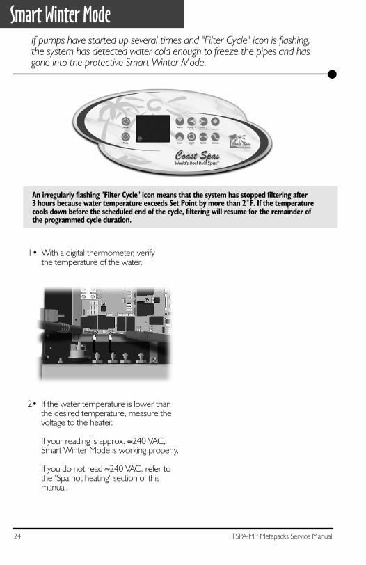
Smart Winter ModeIf pumps have started up several times and "Filter Cycle" icon is flashing, the system has detected water cold enough to freeze the pipes and has gone into the protective Smart Winter Mode.
2• If the water temperature is lower thanthe desired temperature, measure thevoltage to the heater.
If your reading is approx. ≈240 VAC, Smart Winter Mode is working properly.
If you do not read ≈240 VAC, refer to the "Spa not heating" section of this manual.
1• With a digital thermometer, verifythe temperature of the water.
An irregularly flashing "Filter Cycle" icon means that the system has stopped filtering after3 hours because water temperature exceeds Set Point by more than 2˚F. If the temperaturecools down before the scheduled end of the cycle, filtering will resume for the remainder ofthe programmed cycle duration.
25TSPA-MP Metapacks Service Manual
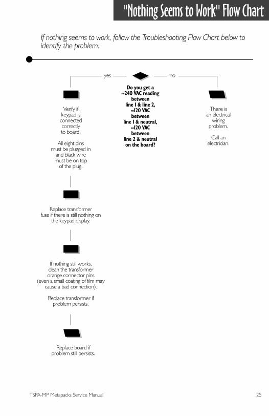
"Nothing Seems to Work" Flow Chart
Do you get a≈240 VAC reading
betweenline 1 & line 2,≈120 VACbetween
line 1 & neutral,≈120 VACbetween
line 2 & neutralon the board?
Verify ifkeypad is
connectedcorrectlyto board.
All eight pinsmust be plugged in
and black wiremust be on top
of the plug.
Replace transformerfuse if there is still nothing on
the keypad display.
There isan electrical
wiringproblem.
Call anelectrician.
Replace board ifproblem still persists.
yes no
If nothing seems to work, follow the Troubleshooting Flow Chart below to identify the problem:
If nothing still works,clean the transformerorange connector pins
(even a small coating of film maycause a bad connection).
Replace transformer ifproblem persists.
26 TSPA-MP Metapacks Service Manual
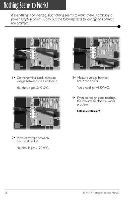
Nothing Seems to Work!
1• On the terminal block, measure voltage between line 1 and line 2.
You should get ≈240 VAC.
If everything is connected, but nothing seems to work, there is probably a power supply problem. Carry out the following tests to identify and correct the problem:
4• If you do not get good readings,this indicates an electrical wiringproblem.
Call an electrician!
3• Measure voltage betweenline 2 and neutral.
You should get ≈120 VAC.
2• Measure voltage betweenline 1 and neutral.
You should get ≈120 VAC.
27TSPA-MP Metapacks Service Manual
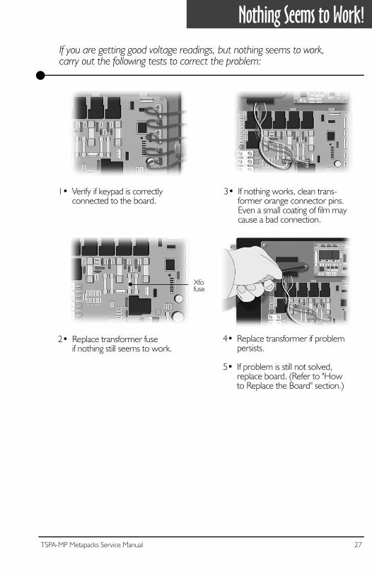
Nothing Seems to Work!
1• Verify if keypad is correctlyconnected to the board.
If you are getting good voltage readings, but nothing seems to work,carry out the following tests to correct the problem:
3• If nothing works, clean trans-former orange connector pins.Even a small coating of film maycause a bad connection.
4• Replace transformer if problempersists.
5• If problem is still not solved,replace board. (Refer to "Howto Replace the Board" section.)
2• Replace transformer fuseif nothing still seems to work.
Xfofuse

28 TSPA-MP Metapacks Service Manual
29TSPA-MP Metapacks Service Manual
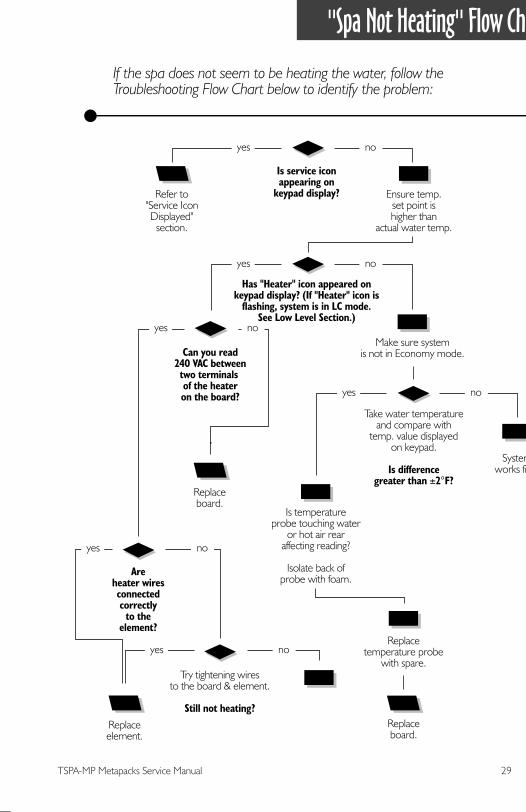
"Spa Not Heating" Flow Chart
Is service iconappearing on
keypad display?Refer to"Service IconDisplayed"
section.
Has "Heater" icon appeared onkeypad display? (If "Heater" icon is
flashing, system is in LC mode.See Low Level Section.)
yes no
yes no
If the spa does not seem to be heating the water, follow the Troubleshooting Flow Chart below to identify the problem:
Ensure temp.set point ishigher than
actual water temp.
Make sure systemis not in Economy mode.
Replaceelement.
Replaceboard.
yes no
Can you read240 VAC betweentwo terminals of the heateron the board?
Areheater wiresconnectedcorrectly
to theelement?
Try tightening wiresto the board & element.
Still not heating?
yes no
yes no
yes no
Take water temperatureand compare with
temp. value displayedon keypad.
Is differencegreater than ±2°F?
Is temperatureprobe touching water
or hot air rearaffecting reading?
Isolate back ofprobe with foam.
Replacetemperature probe
with spare.
Systemworks fine.
Replaceboard.
30 TSPA-MP Metapacks Service Manual
Spa Not Heating!
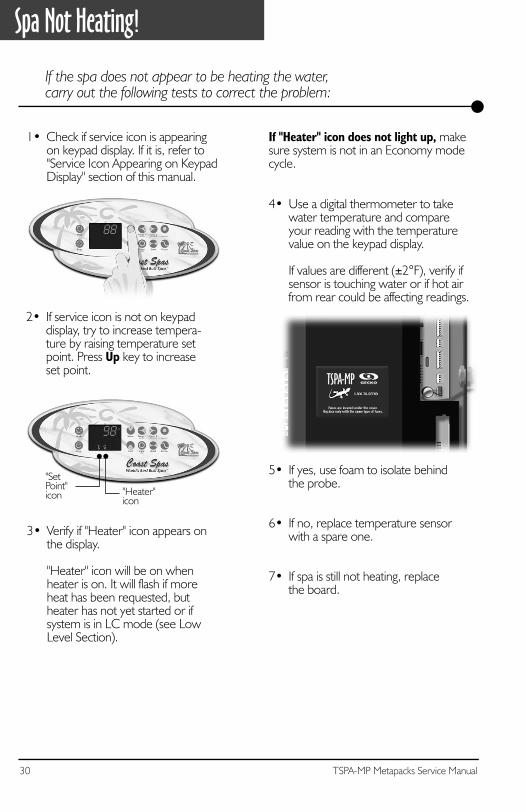
4• Use a digital thermometer to takewater temperature and compareyour reading with the temperaturevalue on the keypad display.
If values are different (±2°F), verify ifsensor is touching water or if hot airfrom rear could be affecting readings.
5• If yes, use foam to isolate behindthe probe.
6• If no, replace temperature sensorwith a spare one.
7• If spa is still not heating, replacethe board.
If "Heater" icon does not light up, makesure system is not in an Economy modecycle.
If the spa does not appear to be heating the water,carry out the following tests to correct the problem:
1• Check if service icon is appearing on keypad display. If it is, refer to"Service Icon Appearing on KeypadDisplay" section of this manual.
3• Verify if "Heater" icon appears onthe display.
"Heater" icon will be on when heater is on. It will flash if moreheat has been requested, butheater has not yet started or ifsystem is in LC mode (see LowLevel Section).
"Heater"icon
"SetPoint"icon
2• If service icon is not on keypaddisplay, try to increase tempera-ture by raising temperature setpoint. Press Up key to increaseset point.
31TSPA-MP Metapacks Service Manual
Spa Not Heating!
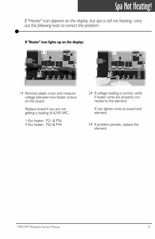
1• Remove plastic cover and measurevoltage between two heater screwson the board.
Replace board if you are notgetting a reading of ≈240 VAC.
1-Kw heater: P21 & P564-Kw heater: P63 & P44
If "Heater" icon appears on the display, but spa is still not heating, carry out the following tests to correct the problem:
2• If voltage reading is correct, verifyif heater wires are properly con-nected to the element.
If not, tighten wires to board andelement.
3• If problem persists, replace theelement.
If "Heater" icon lights up on the display:

32 TSPA-MP Metapacks Service Manual
33TSPA-MP Metapacks Service Manual
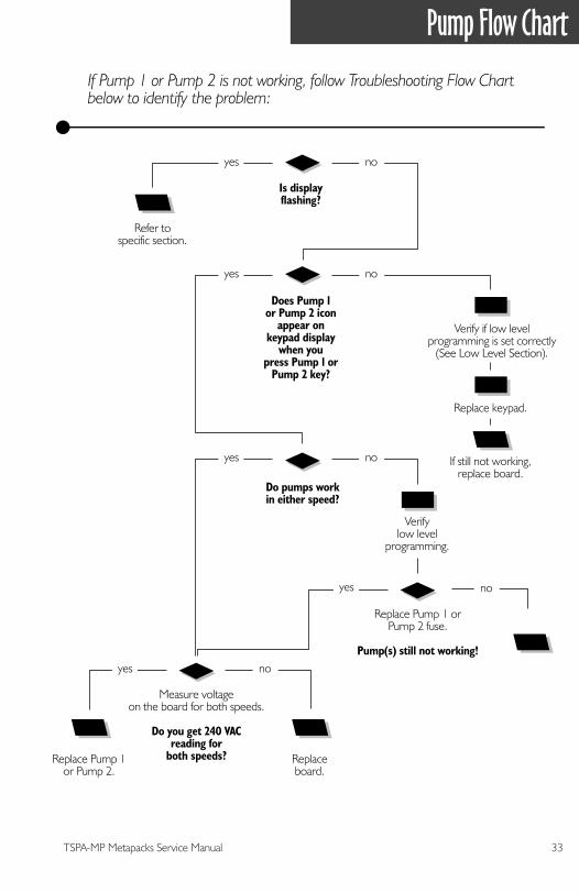
Pump Flow Chart
Is displayflashing?
Refer tospecific section.
Does Pump 1or Pump 2 icon
appear onkeypad display
when youpress Pump 1 or
Pump 2 key?
Do pumps workin either speed?
yes no
yes no
yes no
Replace Pump 1or Pump 2.
Replaceboard.
Measure voltageon the board for both speeds.
Do you get 240 VACreading for
both speeds?
yes no
Replace Pump 1 orPump 2 fuse.
Pump(s) still not working!
yes no
If Pump 1 or Pump 2 is not working, follow Troubleshooting Flow Chart below to identify the problem:
Verifylow level
programming.
Replace keypad.
If still not working,replace board.
Verify if low levelprogramming is set correctly
(See Low Level Section).
34 TSPA-MP Metapacks Service Manual
Pump 1 Does Not Work!
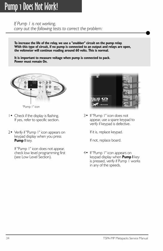
If Pump 1 is not working,carry out the following tests to correct the problem:
To increase the life of the relay, we use a "snubber" circuit on the pump relay.With this type of circuit, if no pump is connected to an output and relays are open, the voltmeter will continue reading around 60 volts. This is normal.
It is important to measure voltage when pump is connected to pack.Power must remain On.
2• Verify if "Pump 1" icon appears onkeypad display when you pressPump 1 key.
If "Pump 1" icon does not appear,check low level programming first(see Low Level Section).
1• Check if the display is flashing.If yes, refer to specific section.
4• If "Pump 1" icon appears onkeypad display when Pump 1 keyis pressed, verify if Pump 1 worksin any of the speeds.
3• If "Pump 1" icon does notappear, use a spare keypad toverify if keypad is defective.
If it is, replace keypad.
If not, replace board.
"Pump 1" icon
35TSPA-MP Metapacks Service Manual
Pump 1 Does Not Work!
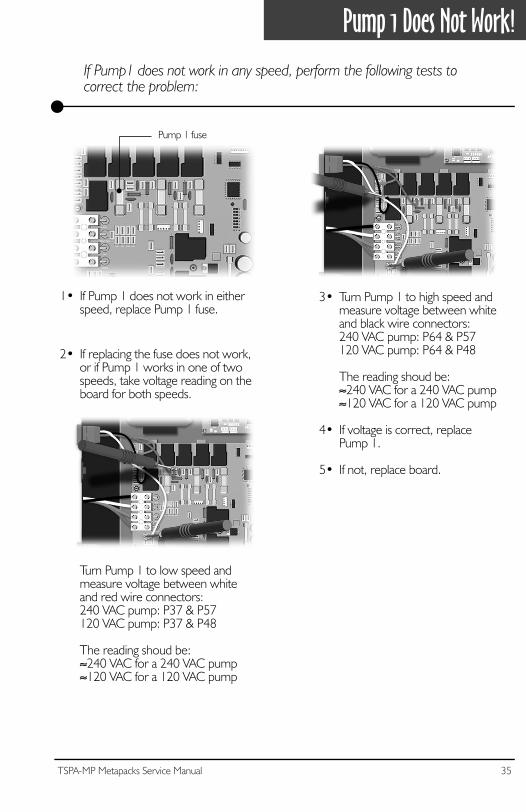
1• If Pump 1 does not work in eitherspeed, replace Pump 1 fuse.
Turn Pump 1 to low speed andmeasure voltage between whiteand red wire connectors:240 VAC pump: P37 & P57120 VAC pump: P37 & P48
The reading shoud be:≈240 VAC for a 240 VAC pump≈120 VAC for a 120 VAC pump
If Pump1 does not work in any speed, perform the following tests to correct the problem:
2• If replacing the fuse does not work,or if Pump 1 works in one of twospeeds, take voltage reading on theboard for both speeds.
3• Turn Pump 1 to high speed andmeasure voltage between whiteand black wire connectors:240 VAC pump: P64 & P57120 VAC pump: P64 & P48
The reading shoud be:≈240 VAC for a 240 VAC pump≈120 VAC for a 120 VAC pump
4• If voltage is correct, replacePump 1.
5• If not, replace board.
Pump 1 fuse
36 TSPA-MP Metapacks Service Manual
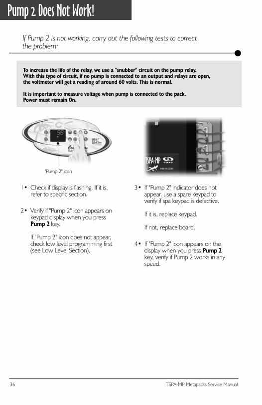
Pump 2 Does Not Work!
If Pump 2 is not working, carry out the following tests to correctthe problem:
To increase the life of the relay, we use a "snubber" circuit on the pump relay.With this type of circuit, if no pump is connected to an output and relays are open, the voltmeter will get a reading of around 60 volts. This is normal.
It is important to measure voltage when pump is connected to the pack.Power must remain On.
2• Verify if "Pump 2" icon appears onkeypad display when you pressPump 2 key.
If "Pump 2" icon does not appear,check low level programming first(see Low Level Section).
4• If "Pump 2" icon appears on thedisplay when you press Pump 2key, verify if Pump 2 works in anyspeed.
1• Check if display is flashing. If it is,refer to specific section.
3• If "Pump 2" indicator does not appear, use a spare keypad to verify if spa keypad is defective.
If it is, replace keypad.
If not, replace board.
"Pump 2" icon
37TSPA-MP Metapacks Service Manual
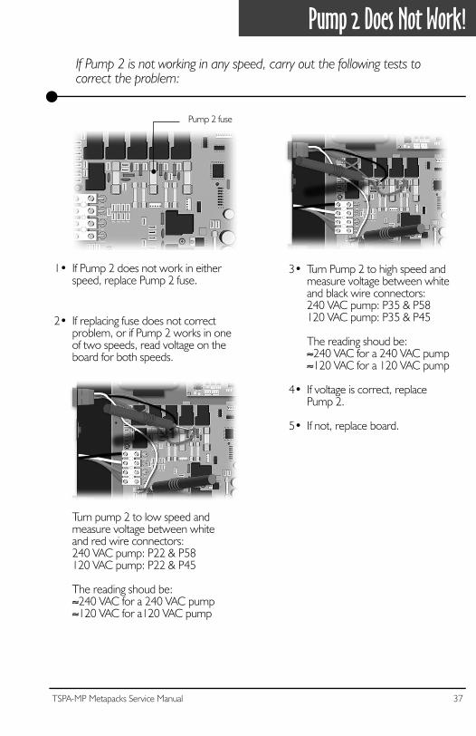
Pump 2 Does Not Work!
1• If Pump 2 does not work in eitherspeed, replace Pump 2 fuse.
Turn pump 2 to low speed and measure voltage between whiteand red wire connectors:240 VAC pump: P22 & P58120 VAC pump: P22 & P45
The reading shoud be:≈240 VAC for a 240 VAC pump≈120 VAC for a120 VAC pump
If Pump 2 is not working in any speed, carry out the following tests to correct the problem:
2• If replacing fuse does not correctproblem, or if Pump 2 works in oneof two speeds, read voltage on the board for both speeds.
3• Turn Pump 2 to high speed and measure voltage between whiteand black wire connectors:240 VAC pump: P35 & P58120 VAC pump: P35 & P45
The reading shoud be:≈240 VAC for a 240 VAC pump≈120 VAC for a 120 VAC pump
4• If voltage is correct, replacePump 2.
5• If not, replace board.
Pump 2 fuse

38 TSPA-MP Metapacks Service Manual
39TSPA-MP Metapacks Service Manual
Blower Flow Chart
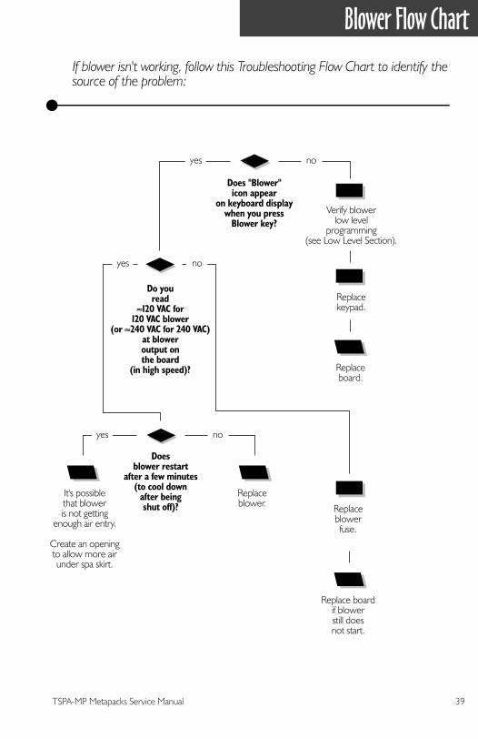
If blower isn't working, follow this Troubleshooting Flow Chart to identify the source of the problem:
Does "Blower"icon appear
on keyboard displaywhen you press
Blower key?
Do youread
≈120 VAC for120 VAC blower
(or ≈240 VAC for 240 VAC)at bloweroutput onthe board
(in high speed)?
Replaceblowerfuse.
It's possiblethat bloweris not getting
enough air entry.
Create an openingto allow more airunder spa skirt.
Replace boardif blowerstill doesnot start.
Replaceblower.
yes
yes no
no
Doesblower restart
after a few minutes(to cool down
after beingshut off)?
yes no
Verify blowerlow level
programming(see Low Level Section).
Replacekeypad.
Replaceboard.
40 TSPA-MP Metapacks Service Manual
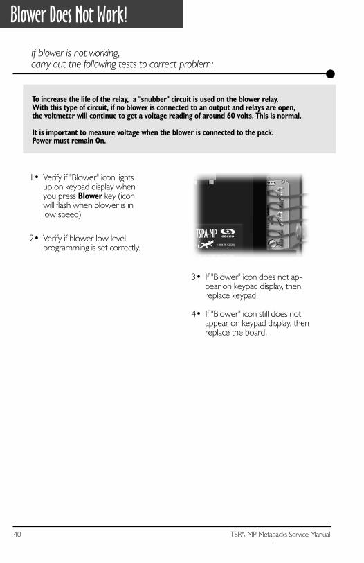
Blower Does Not Work!
If blower is not working,carry out the following tests to correct problem:
To increase the life of the relay, a "snubber" circuit is used on the blower relay.With this type of circuit, if no blower is connected to an output and relays are open, the voltmeter will continue to get a voltage reading of around 60 volts. This is normal.
It is important to measure voltage when the blower is connected to the pack.Power must remain On.
1• Verify if "Blower" icon lightsup on keypad display whenyou press Blower key (iconwill flash when blower is inlow speed).
3• If "Blower" icon does not ap-pear on keypad display, thenreplace keypad.
4• If "Blower" icon still does notappear on keypad display, thenreplace the board.
2• Verify if blower low levelprogramming is set correctly.
41TSPA-MP Metapacks Service Manual
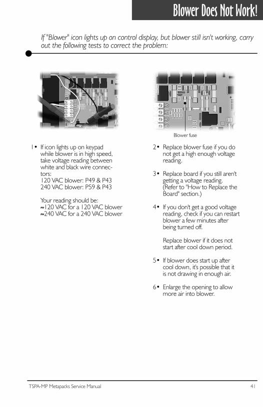
Blower Does Not Work!
1• If icon lights up on keypadwhile blower is in high speed,take voltage reading betweenwhite and black wire connec-tors:120 VAC blower: P49 & P43240 VAC blower: P59 & P43
Your reading should be:≈120 VAC for a 120 VAC blower≈240 VAC for a 240 VAC blower
2• Replace blower fuse if you donot get a high enough voltagereading.
3• Replace board if you still aren'tgetting a voltage reading.(Refer to "How to Replace theBoard" section.)
4• If you don't get a good voltagereading, check if you can restartblower a few minutes afterbeing turned off.
Replace blower if it does notstart after cool down period.
5• If blower does start up aftercool down, it's possible that itis not drawing in enough air.
6• Enlarge the opening to allowmore air into blower.
If "Blower" icon lights up on control display, but blower still isn't working, carry out the following tests to correct the problem:
Blower fuse

42 TSPA-MP Metapacks Service Manual
43TSPA-MP Metapacks Service Manual
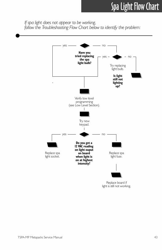
Spa Light Flow Chart
Have youtried replacing
the spalight bulb?
Do you get a12 VAC readingon light ouput
on boardwhen light ison at highest
intensity?
Replace spalight fuse.
Replace board iflight is still not working.
Replace spalight socket.
Try replacinglight bulb.
Is lightstill notlighting
up?
yes
yes no
no
yes no
If spa light does not appear to be working,follow the Troubleshooting Flow Chart below to identify the problem:
Try newkeypad.
Verify low levelprogramming
(see Low Level Section).
44 TSPA-MP Metapacks Service Manual
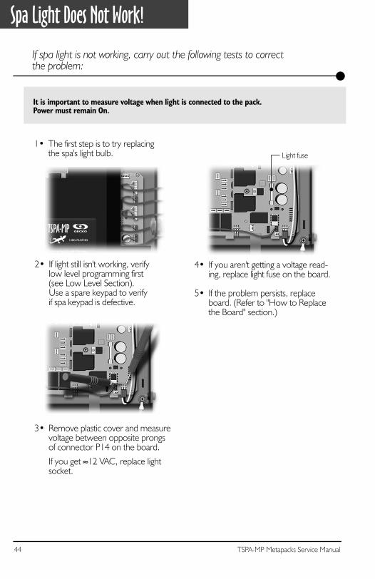
Spa Light Does Not Work!
If spa light is not working, carry out the following tests to correctthe problem:
It is important to measure voltage when light is connected to the pack.Power must remain On.
1• The first step is to try replacingthe spa's light bulb.
3• Remove plastic cover and measurevoltage between opposite prongsof connector P14 on the board.
If you get ≈12 VAC, replace lightsocket.
4• If you aren't getting a voltage read-ing, replace light fuse on the board.
5• If the problem persists, replace board. (Refer to "How to Replacethe Board" section.)
Light fuse
2• If light still isn't working, verify low level programming first(see Low Level Section). Use a spare keypad to verifyif spa keypad is defective.
45TSPA-MP Metapacks Service Manual
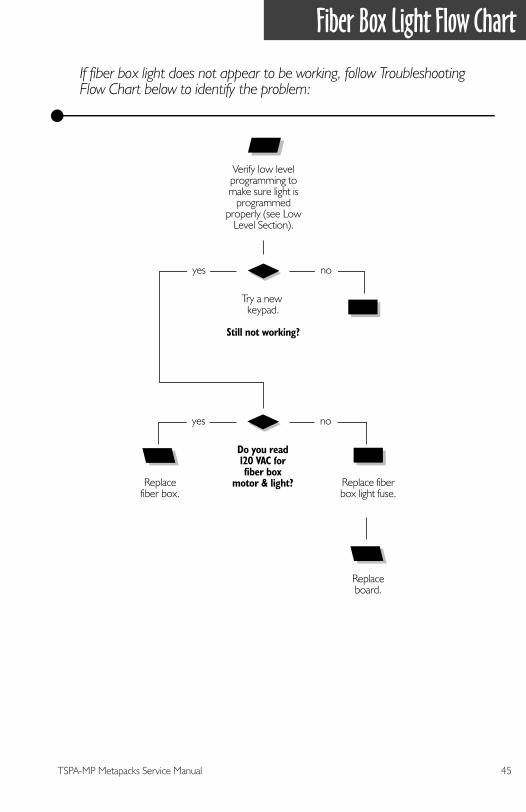
Fiber Box Light Flow Chart
Try a new keypad.
Still not working?
yes no
Do you read120 VAC forfiber box
motor & light? Replace fiberbox light fuse.
Replaceboard.
Replacefiber box.
yes no
If fiber box light does not appear to be working, follow Troubleshooting Flow Chart below to identify the problem:
Verify low levelprogramming tomake sure light is
programmedproperly (see Low
Level Section).
46 TSPA-MP Metapacks Service Manual
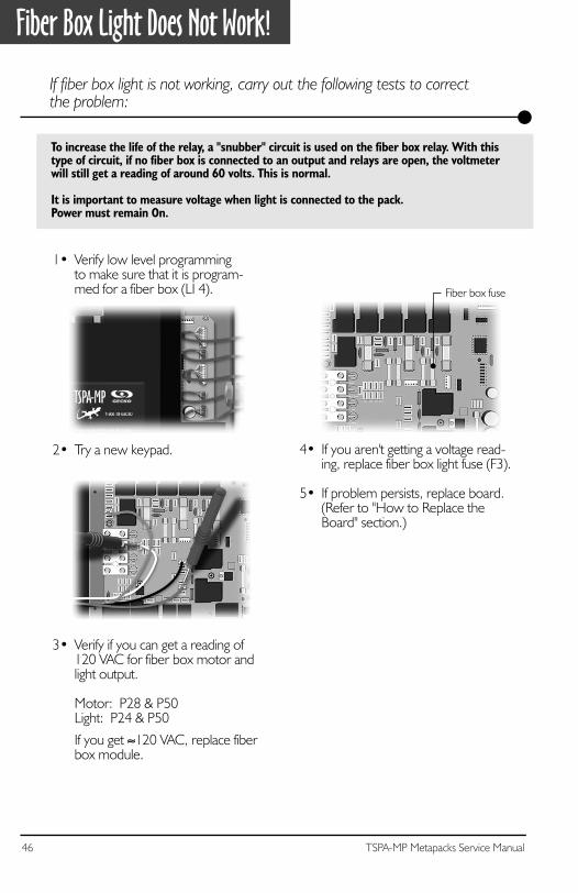
Fiber Box Light Does Not Work!
If fiber box light is not working, carry out the following tests to correctthe problem:
To increase the life of the relay, a "snubber" circuit is used on the fiber box relay. With thistype of circuit, if no fiber box is connected to an output and relays are open, the voltmeterwill still get a reading of around 60 volts. This is normal.
It is important to measure voltage when light is connected to the pack.Power must remain On.
1• Verify low level programmingto make sure that it is program-med for a fiber box (LI 4).
2• Try a new keypad.
3• Verify if you can get a reading of120 VAC for fiber box motor andlight output.
Motor: P28 & P50Light: P24 & P50
If you get ≈120 VAC, replace fiberbox module.
4• If you aren't getting a voltage read-ing, replace fiber box light fuse (F3).
5• If problem persists, replace board.(Refer to "How to Replace theBoard" section.)
Fiber box fuse
47TSPA-MP Metapacks Service Manual
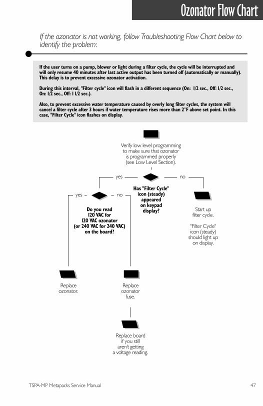
Ozonator Flow Chart
If the ozonator is not working, follow Troubleshooting Flow Chart below to identify the problem:
Verify low level programmingto make sure that ozonator
is programmed properly(see Low Level Section).
Has "Filter Cycle"icon (steady)
appearedon keypaddisplay?Do you read
120 VAC for120 VAC ozonator
(or 240 VAC for 240 VAC)on the board?
Start upfilter cycle.
"Filter Cycle"icon (steady)
should light upon display.
Replaceozonator
fuse.
Replace boardif you still
aren't gettinga voltage reading.
yes
yes no
no
Replaceozonator.
If the user turns on a pump, blower or light during a filter cycle, the cycle will be interrupted andwill only resume 40 minutes after last active output has been turned off (automatically or manually).This delay is to prevent excessive ozonator activation.
During this interval, "Filter cycle" icon will flash in a different sequence (On: 1/2 sec., Off: 1/2 sec.,On: 1/2 sec., Off: 1 1/2 sec.).
Also, to prevent excessive water temperature caused by overly long filter cycles, the system willcancel a filter cycle after 3 hours if water temperature rises more than 2°F above set point. In thiscase, "Filter Cycle" icon flashes on display.
48 TSPA-MP Metapacks Service Manual
Ozonator Does Not Work!
If ozonator isn't working, carry out the following tests to correctthe problem:
To increase the life of the relay, a "snubber" circuit is used on the ozonator relay. Withthis type of circuit, if no ozonator is connected to an output and relays are open, thevoltmeter will still get a reading of around 60 volts. This is normal.
It is important to take voltage reading with ozonator connected to the pack.Power must remain On.
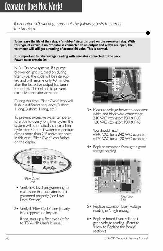
2• Verify if "Filter Cycle" icon (steadyicon) appears on keypad.
If not, start up a filter cycle (referto TSPA-MP User's Manual).
1• Verify low level programming tomake sure that ozonator is pro-grammed properly (see LowLevel Section).
N.B.: On new systems, if a pump, blower or light is turned on duringfilter cycle, the cycle will be interrup-ted and will resume only 40 minutes after the last active output has beenturned off. This delay is to preventexcessive ozonator activation.
During this time, "Filter Cycle" icon willflash in a different sequence (3 short,1 long, 3 short, 1 long, etc.).
To prevent excessive water tempera- ture due to overly long filter cycles, thesystem will automatically cancel a filtercycle after 3 hours if water temperatureclimbs more than 2°F above set point.In this case, "Filter Cycle" icon flasheson the display.
3• Measure voltage between ozonatorwhite and black wire connectors:240 VAC ozonator: P30 & P60120 VAC ozonator: P30 & P46
You should read:≈240 VAC for a 240 VAC ozonator≈120 VAC for a 120 VAC ozonator
4• Replace ozonator if you get a goodvoltage reading.
"Filter Cycle" icon
5• Replace ozonator fuse if voltagereading isn't high enough.
6• Replace board if you still don'tget a voltage reading. (Refer to"How to Replace the Board"section.)
Ozonatorfuse
49TSPA-MP Metapacks Service Manual
Circulation Pump Flow Chart
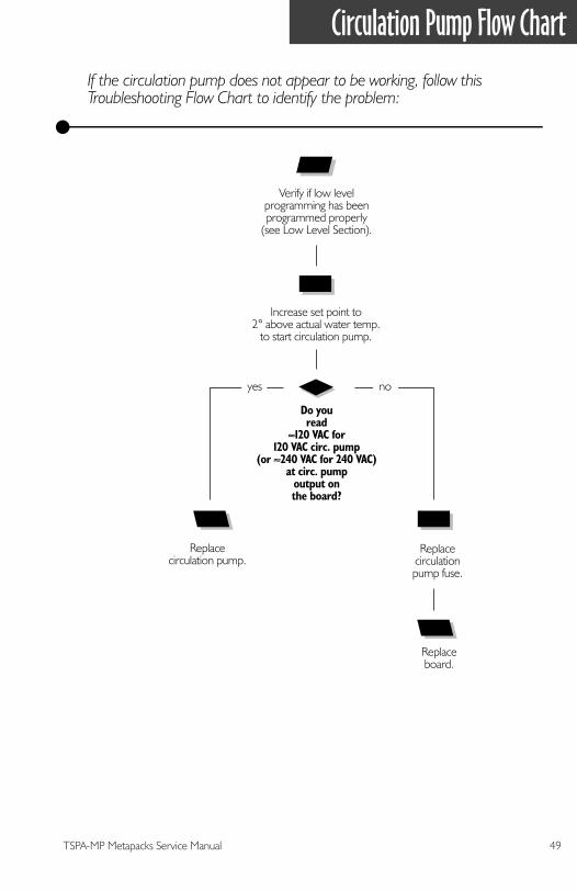
If the circulation pump does not appear to be working, follow this Troubleshooting Flow Chart to identify the problem:
Replacecirculationpump fuse.
Replacecirculation pump.
Replaceboard.
Do youread
≈120 VAC for120 VAC circ. pump
(or ≈240 VAC for 240 VAC)at circ. pump
output onthe board?
Increase set point to2° above actual water temp.
to start circulation pump.
Verify if low levelprogramming has beenprogrammed properly
(see Low Level Section).
yes no
50 TSPA-MP Metapacks Service Manual
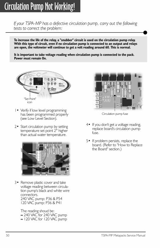
Circulation Pump Not Working!
If your TSPA-MP has a defective circulation pump, carry out the following tests to correct the problem:
To increase the life of the relay, a "snubber" circuit is used on the circulation pump relay. With this type of circuit, even if no circulation pump is connected to an output and relays are open, the voltmeter will continue to get a volt reading around 60. This is normal.
It is important to take voltage reading when circulation pump is connected to the pack.Power must remain On.
1• Verify if low level programminghas been programmed properly(see Low Level Section).
2• Start circulation pump by settingtemperature set point 2° higherthan actual water temperature.
4• If you don't get a voltage reading,replace board's circulation pumpfuse.
5• If problem persists, replace the board. (Refer to "How to Replacethe Board" section.)
Circulation pump fuse
"Set Point"icon
3• Remove plastic cover and takevoltage reading between circula-tion pump's black and white wireconnectors. 240 VAC pump: P36 & P54
120 VAC pump: P36 & P41
The reading shoud be:≈ 240 VAC for 240 VAC pump≈ 120 VAC for 120 VAC pump
51TSPA-MP Metapacks Service Manual
Keys Flow Chart
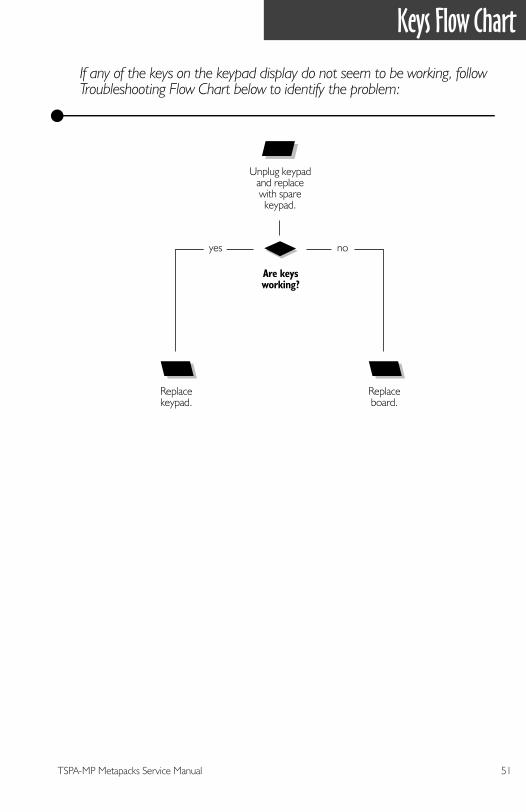
If any of the keys on the keypad display do not seem to be working, follow Troubleshooting Flow Chart below to identify the problem:
Replacekeypad.
Replaceboard.
Are keysworking?
yes no
Unplug keypadand replacewith sparekeypad.
52 TSPA-MP Metapacks Service Manual
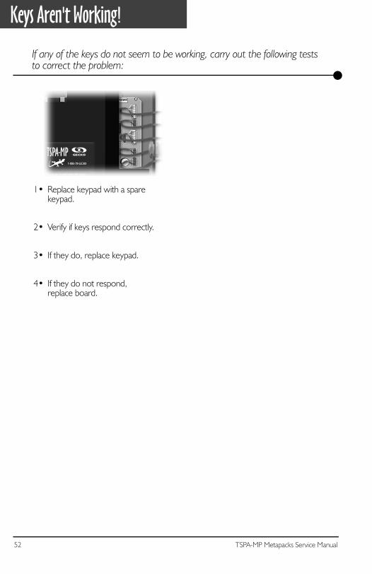
Keys Aren't Working!
1• Replace keypad with a sparekeypad.
2• Verify if keys respond correctly.
3• If they do, replace keypad.
4• If they do not respond,replace board.
If any of the keys do not seem to be working, carry out the following tests to correct the problem:
53TSPA-MP Metapacks Service Manual
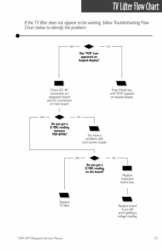
TV Lifter Flow Chart
If the TV lifter does not appear to be working, follow Troubleshooting Flow Chart below to identify the problem:
Press Mode keyuntil "VCR" appearson keypad display.
Has "VCR" iconappeared on
keypad display?
yes no
Check I2C #1connection on
expansion boardand I2C connection
on main board.
You have aproblem with
your power supply.
Do you get a12 VDC reading
betweenP101 &P116?
yes no
Replaceexpansionboard fuse.
ReplaceTV lifter. Replace board
if you stillaren't getting avoltage reading.
Do you get a12 VDC readingon the board?
yes no
54 TSPA-MP Metapacks Service Manual
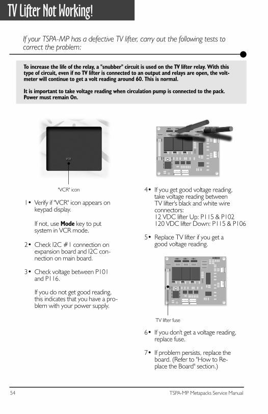
TV Lifter Not Working!
If your TSPA-MP has a defective TV lifter, carry out the following tests to correct the problem:
To increase the life of the relay, a "snubber" circuit is used on the TV lifter relay. With thistype of circuit, even if no TV lifter is connected to an output and relays are open, the volt-meter will continue to get a volt reading around 60. This is normal.
It is important to take voltage reading when circulation pump is connected to the pack.Power must remain On.
1• Verify if "VCR" icon appears onkeypad display.
If not, use Mode key to putsystem in VCR mode.
2• Check I2C #1 connection onexpansion board and I2C con-nection on main board.
3• Check voltage between P101and P116.
If you do not get good reading,this indicates that you have a pro-blem with your power supply.
6• If you don't get a voltage reading,replace fuse.
7• If problem persists, replace theboard. (Refer to "How to Re-place the Board" section.)
TV lifter fuse
"VCR" icon 4• If you get good voltage reading,take voltage reading betweenTV lifter's black and white wireconnectors:12 VDC lifter Up: P115 & P102120 VDC lifter Down: P115 & P106
5• Replace TV lifter if you get agood voltage reading.
55TSPA-MP Metapacks Service Manual
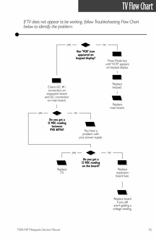
TV Flow Chart
If TV does not appear to be working, follow Troubleshooting Flow Chart below to identify the problem:
Replacemain board.
Has "VCR" iconappeared on
keypad display?
yes no
Press Mode keyuntil "VCR" appearson keypad display.
Replacekeypad.
Replaceexpansionboard fuse.
ReplaceTV.
Replace boardif you still
aren't getting avoltage reading.
Do you get a12 VDC readingon the board?
yes no
Check I2C #1connection on
expansion boardand I2C connection
on main board.
You have aproblem with
your power supply.
Do you get a12 VDC reading
betweenP101 &P116?
yes no
56 TSPA-MP Metapacks Service Manual
TV Not Working!
If your TV is not working, carry out the following tests to correct the problem:
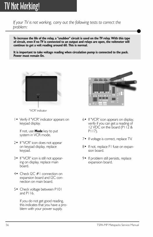
To increase the life of the relay, a "snubber" circuit is used on the TV relay. With this typeof circuit, even if no TV is connected to an output and relays are open, the voltmeter willcontinue to get a volt reading around 60. This is normal.
It is important to take voltage reading when circulation pump is connected to the pack.Power must remain On.
1• Verify if "VCR" indicator appears onkeypad display.
If not, use Mode key to putsystem in VCR mode.
2• If "VCR" icon does not appearon keypad display, replacekeypad.
3• If "VCR" icon is still not appear-ing on display, replace mainboard.
6• If "VCR" icon appears on display,verify if you can get a reading of12 VDC on the board (P112 &P117).
7• If voltage is correct, replace TV.
8• If not, replace F1 fuse on expan-sion board.
9• If problem still persists, replaceexpansion board.
"VCR" indicator
4• Check I2C #1 connection onexpansion board and I2C con-nection on main board.
5• Check voltage between P101and P116.
If you do not get good reading,this indicates that you have a pro-blem with your power supply.
57TSPA-MP Metapacks Service Manual
VCR/DVD & CD/Radio Flow Chart
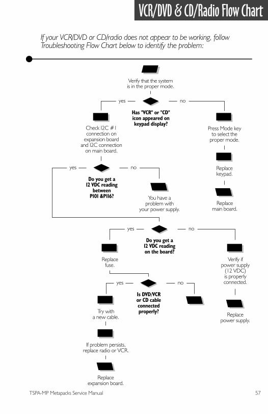
If your VCR/DVD or CD/radio does not appear to be working, follow Troubleshooting Flow Chart below to identify the problem:
Has "VCR" or "CD"icon appeared onkeypad display?
yes no
Replacemain board.
Press Mode keyto select the
proper mode.
Replacekeypad.
Verify ifpower supply
(12 VDC)is properlyconnected.
Replacefuse.
Replacepower supply.
Do you get a12 VDC readingon the board?
yes no
Try witha new cable.
If problem persists,replace radio or VCR.
Replaceexpansion board.
Is DVD/VCRor CD cableconnectedproperly?
yes no
Verify that the systemis in the proper mode.
Check I2C #1connection on
expansion boardand I2C connection
on main board.
You have aproblem with
your power supply.
Do you get a12 VDC reading
betweenP101 &P116?
yes no
58 TSPA-MP Metapacks Service Manual
VCR/DVD & CD/Radio Not Working!
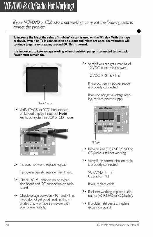
If your VCR/DVD or CD/radio is not working, carry out the following tests to correct the problem:
To increase the life of the relay, a "snubber" circuit is used on the TV relay. With this typeof circuit, even if no TV is connected to an output and relays are open, the voltmeter willcontinue to get a volt reading around 60. This is normal.
It is important to take voltage reading when circulation pump is connected to the pack.Power must remain On.
1• Verify if "VCR" or "CD" icon appearson keypad display. If not, use Modekey to put system in VCR or CD mode.
5• Verify if you can get a reading of12 VDC at incoming power.
12 VDC: P101 & P116
If you do, verify if power supplyis properly connected.
If you do not get a voltage read-ing, replace power supply.
6• Replace fuse (F1) if VCR/DVD orCD/radio is still not working.
7• Verify if the communication cableis properly connected.
VCR/DVD: P119CD/radio: P121
If yes, replace cable.
8• If still not working, replace audiooutput (VCR/DVD or CD/radio).
9• If problem still persists, replaceexpansion board.
2• If it does not work, replace keypad.
If problem persists, replace main board.
3• Check I2C #1 connection on expan-sion board and I2C connection on mainboard.
4• Check voltage between P101 and P116.If you do not get good reading, this in-dicates that you have a problem withyour power supply.
F1 fuse
"Audio" icon
59TSPA-MP Metapacks Service Manual
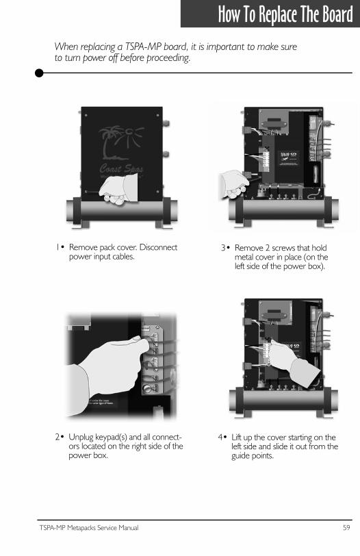
How To Replace The Board
When replacing a TSPA-MP board, it is important to make sureto turn power off before proceeding.
1• Remove pack cover. Disconnectpower input cables.
3• Remove 2 screws that holdmetal cover in place (on theleft side of the power box).
4• Lift up the cover starting on theleft side and slide it out from theguide points.
2• Unplug keypad(s) and all connect-ors located on the right side of thepower box.
60 TSPA-MP Metapacks Service Manual
How To Replace The Board
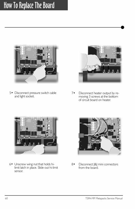
5• Disconnect pressure switch cableand light socket.
7• Disconnect heater output by re-moving 3 screws at the bottomof circuit board on heater.
8• Disconnect J&J mini connectorsfrom the board.
6• Unscrew wing nut that holds hi-limit latch in place. Slide out hi-limitsensor.
61TSPA-MP Metapacks Service Manual
How To Replace The Board
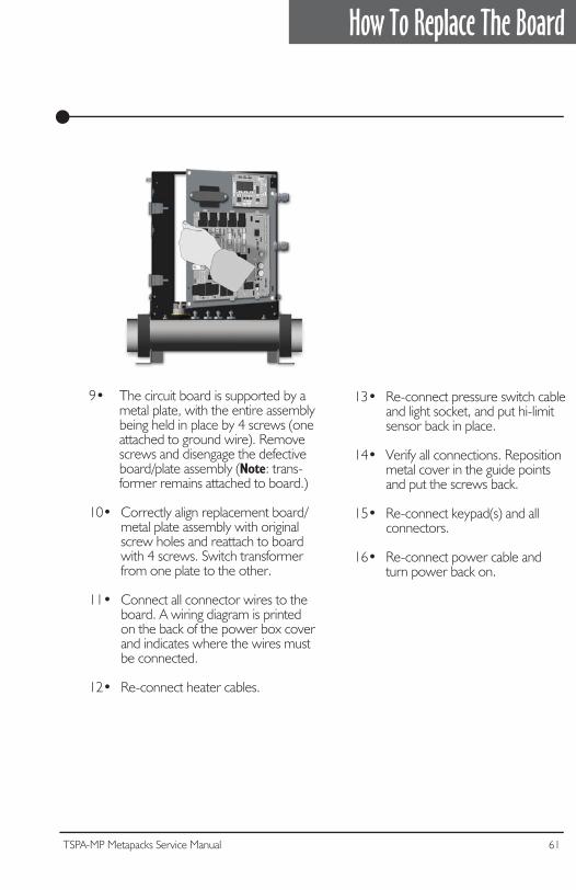
9• The circuit board is supported by a metal plate, with the entire assembly being held in place by 4 screws (one attached to ground wire). Remove screws and disengage the defective board/plate assembly (Note: trans- former remains attached to board.)
10• Correctly align replacement board/ metal plate assembly with original screw holes and reattach to board with 4 screws. Switch transformer from one plate to the other.
11• Connect all connector wires to the board. A wiring diagram is printed on the back of the power box cover and indicates where the wires must be connected.
12• Re-connect heater cables.
13• Re-connect pressure switch cable and light socket, and put hi-limit sensor back in place.
14• Verify all connections. Reposition metal cover in the guide points and put the screws back. 15• Re-connect keypad(s) and all connectors.
16• Re-connect power cable and turn power back on.

62 TSPA-MP Metapacks Service Manual
63TSPA-MP Metapacks Service Manual
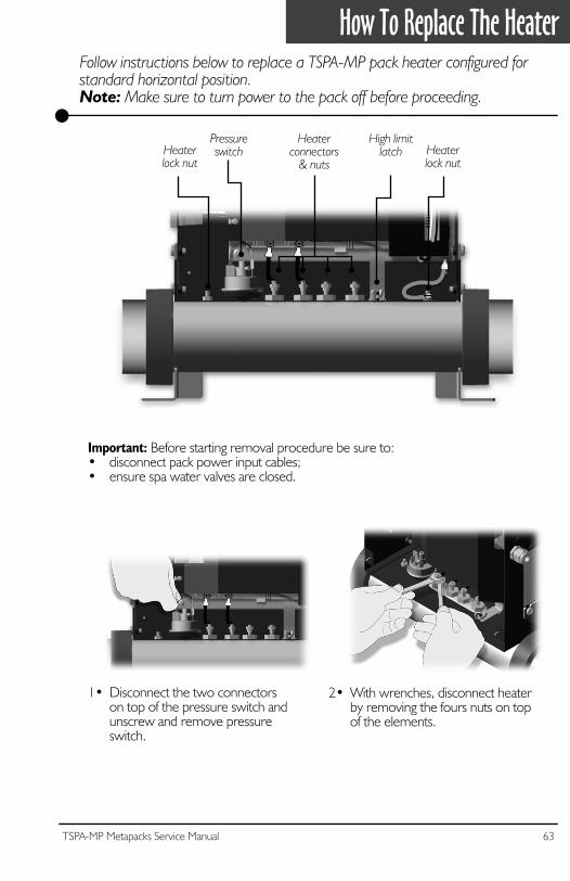
How To Replace The HeaterFollow instructions below to replace a TSPA-MP pack heater configured for standard horizontal position.Note: Make sure to turn power to the pack off before proceeding.
1• Disconnect the two connectorson top of the pressure switch andunscrew and remove pressureswitch.
Important: Before starting removal procedure be sure to:• disconnect pack power input cables;• ensure spa water valves are closed.
2• With wrenches, disconnect heater by removing the fours nuts on top of the elements.
Pressureswitch
Heaterconnectors
& nuts
High limitlatchHeater
lock nutHeaterlock nut
64 TSPA-MP Metapacks Service Manual
How To Replace The Heater
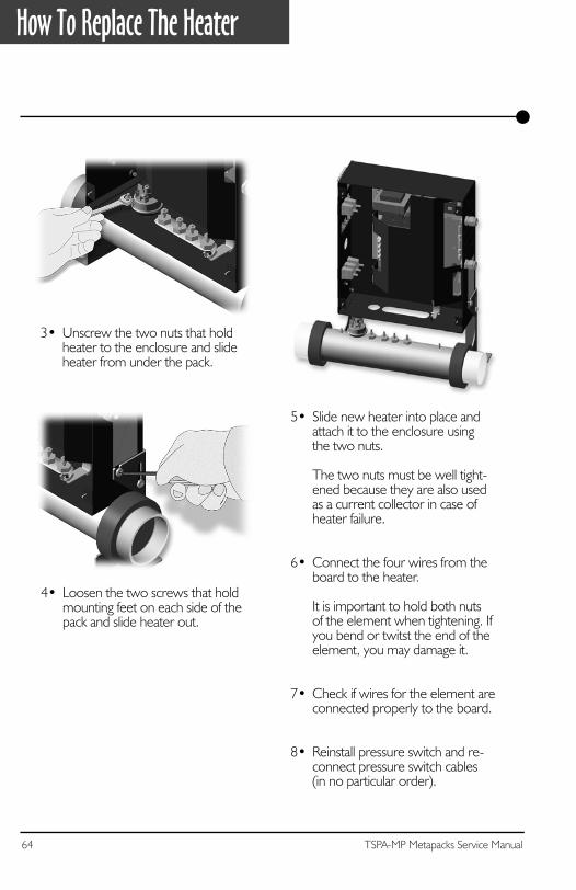
5• Slide new heater into place andattach it to the enclosure usingthe two nuts.
The two nuts must be well tight-ened because they are also usedas a current collector in case ofheater failure.
6• Connect the four wires from theboard to the heater.
It is important to hold both nutsof the element when tightening. Ifyou bend or twitst the end of theelement, you may damage it.
7• Check if wires for the element areconnected properly to the board.
8• Reinstall pressure switch and re-connect pressure switch cables(in no particular order).
4• Loosen the two screws that holdmounting feet on each side of thepack and slide heater out.
3• Unscrew the two nuts that holdheater to the enclosure and slideheater from under the pack.
65TSPA-MP Metapacks Service Manual
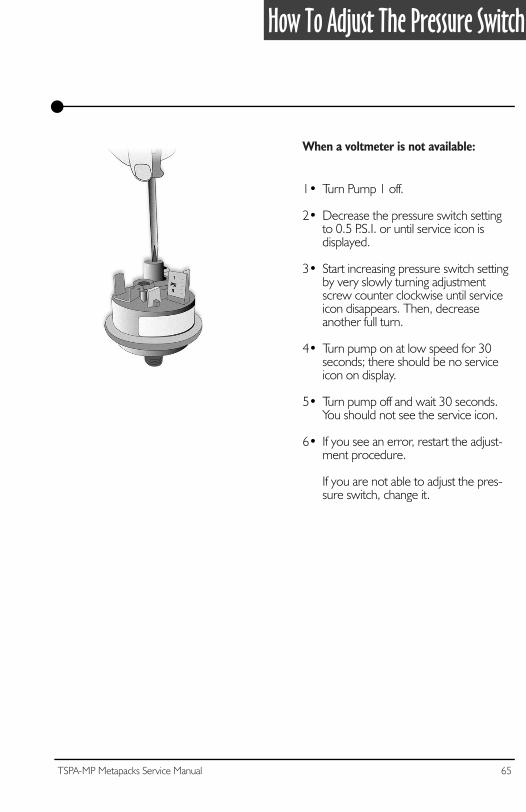
How To Adjust The Pressure Switch
1• Turn Pump 1 off.
2• Decrease the pressure switch settingto 0.5 P.S.I. or until service icon isdisplayed.
3• Start increasing pressure switch settingby very slowly turning adjustmentscrew counter clockwise until serviceicon disappears. Then, decreaseanother full turn.
4• Turn pump on at low speed for 30seconds; there should be no serviceicon on display.
5• Turn pump off and wait 30 seconds. You should not see the service icon.
6• If you see an error, restart the adjust-ment procedure.
If you are not able to adjust the pres-sure switch, change it.
When a voltmeter is not available:
66 TSPA-MP Metapacks Service Manual
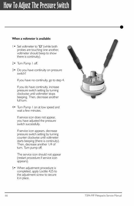
How To Adjust The Pressure Switch
1• Set voltmeter to "Ω" (while both probes are touching one another,voltmeter should beep to show there is continuity).
2• Turn Pump 1 off.
3• Do you have continuity on pressureswitch?
If you have no continuity, go to step 4.
If you do have continuity, increase pressure switch setting by turningclockwise until voltmeter stops beeping. Then, decrease anotherfull turn.
4• Turn Pump 1 on at low speed andwait a few minutes.
If service icon does not appear,you have adjusted the pressureswitch successfully.
If service icon appears, decreasepressure switch setting by turningcounter clockwise until voltmeterstarts beeping (there is continuity).Then, decrease another 1/4 ofturn. Turn pump off.
The service icon should not appear(restart procedure if service iconappears).
5• When adjustment procedure is completed, apply Loctite 425 tothe adjustment screw to secureit in place.
When a voltmeter is available:
67TSPA-MP Metapacks Service Manual
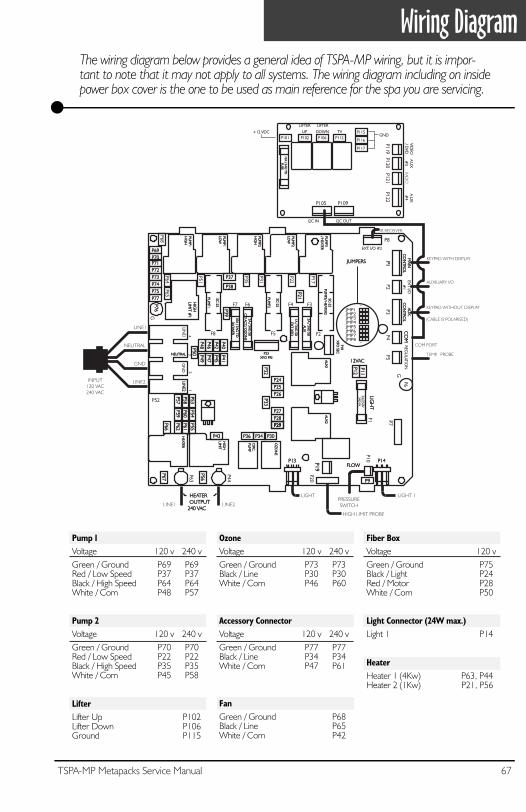
Pump 1Voltage 120 v 240 vGreen / Ground P69 P69Red / Low Speed P37 P37Black / High Speed P64 P64White / Com P48 P57
Pump 2Voltage 120 v 240 vGreen / Ground P70 P70Red / Low Speed P22 P22Black / High Speed P35 P35White / Com P45 P58
LifterLifter Up P102Lifter Down P106Ground P115
OzoneVoltage 120 v 240 vGreen / Ground P73 P73Black / Line P30 P30White / Com P46 P60
Accessory ConnectorVoltage 120 v 240 vGreen / Ground P77 P77Black / Line P34 P34White / Com P47 P61
FanGreen / Ground P68Black / Line P65White / Com P42
Fiber BoxVoltage 120 vGreen / Ground P75Black / Light P24Red / Motor P28White / Com P50
Light Connector (24W max.)Light 1 P14
HeaterHeater 1 (4Kw) P63, P44Heater 2 (1Kw) P21, P56
P7
P63
P52
F1
P44
NEUTRALNEUTRAL
LINE1
LINE2
LINE2
3A/250V3AG
-FA
FLOWFLOW
LIGH
TLIG
HT
12VAC12VACGN
D
LINE2LINE1
43
21
HIG
HLIM
IT #1
HIG
HLIM
IT #1
INPUT120 VAC240 VAC
LINE1
NEUTRAL
GND
LINE2
P3
AUX
.C
ON
TROL
AUX
.C
ON
TROL
EXT I/O#
1EX
T I/O#
1
JMP8JMP7JMP6JMP5JMP4JMP3JMP2JMP1
11
P8
EXT. I/O #2
P1P1
MAIN
CO
NTRO
LM
AINC
ON
TROL
P4
CO
MC
OM
P5
REGU
LATIONP11P11
P10
PUM
P2H
IGH
PUM
P2H
IGH
PUM
P1H
IGH
PUM
P1H
IGH
PUM
P2LO
WPU
MP2
LOW
PUM
P1LO
WPU
MP1
LOW
P70P70
P72P72P71P71
P69P69
P68
P51
P31
P64
P21P21
P38P38
P73P73 P37P37
P50P50 P49
P49P48P48
P39P39
P355A / 3AG
SBC
P/ ACC
/ OZ
ON
E5A / 3AG
SBC
P/ ACC
/ OZ
ON
E
10A / 3AG TD
BLOW
ER10A / 3AG
TDBLO
WER
F6F7
5A / 3AG SB
AUX
5A / 3AG SB
AUX
F3F4
F5
SC-25
PUM
P2
SC-25
PUM
P2
F2
SC-25
PUM
P3/ HEATER2
SC-25
PUM
P3/ HEATER2
F8
SC-25
PUM
P1
SC-25
PUM
P1
1A / 3AG SB
EXT X
FO1A / 3AG
SBEX
T XFO
P18X
FO SEC
P18X
FO SEC
P23XFO PRI
P23XFO PRI
PUM
P3/ H
EATERPU
MP3
/ HEATER
AUX
2AU
X2
AUX
1AU
X1
OZ
ON
EO
ZO
NE
CIRC
.PU
MP
CIRC
.PU
MP
HEATER
HEATER
HIG
HLIM
ITH
IGH
LIMIT
G
G
P53P53P58P58P57P57
P41P41P45P45P47P47
P40P40P42P42P46P46
P55P55P61P61
P54P54P60P60P59P59
P62P62
P66P66
P56P56
P67P67
P75P75P74P74
P77P77
P25P25P24P24
P26P26
P32P32
P28P28P27P27
P33P33
P34P34 P30P30
P19P19
P2
P20
P29P29P29P29
P9P9
P14P14
P65
P6
P76P76
P43P43 P36P36
P12P12
P17
P22
HEATEROUTPUT
240 VAC
HEATEROUTPUT
240 VAC
KEYPAD WITH DISPLAY
(CABLE IS POLARISED)
COM PORT
LIGHT 1
AUXILIARY I/O
PRESSURESWITCH
JUMPERSJUMPERS
TEMP. PROBE
IR RECEIVER
HIGH LIMIT PROBE
KEYPAD WITHOUT DISPLAY
LIGHT
P13P13
P101
AU
X#
4A
UX
#4
P122P102 P106 P112
P115
P116
P117
RADIO
P121
AU
X#
3A
UX
#3
P120
VIDEO
/ DVD
VIDEO
/ DVD
P119
LIFTER
UP
LIFTER
UP
LIFTER
DOWN
LIFTER
DOWN TV
P109P105
I2C INI2C IN I2C OUTI2C OUT
GND+12 VDC+12 VDC
10A / 3A
G T
DFU
SE10A
/ 3AG
TD
FUSE
Wiring DiagramThe wiring diagram below provides a general idea of TSPA-MP wiring, but it is impor-tant to note that it may not apply to all systems. The wiring diagram including on inside power box cover is the one to be used as main reference for the spa you are servicing.

Professional Repair KitAll you need in one case!
• Top side controls (keypads)• Temperature probes• Pressure switch cables • Flow switches• Elements• Heater wires• Transformer• Ground lugs• Gromets• Standoffs• Light cords• Strain reliefs for light cord• Plugs• Fuse kits• Screws
Gecko's professional repair kit contains all you need to service and repairGecko's line of power spa packs.
Call 1.800.78.GECKOto order or for more info!

TSPA-MP SERVICE MANUAL
COMPLETE SERVICE GUIDE WITHSTEP-BY-STEP INSTRUCTIONS ON:
GFCI Troubleshooting•
Jumper Selection•
Understanding& Correcting
Error Conditions•
System Malfunctions•
Part ReplacementsInstructions
•& More
• EQ U
I P PE D W I T H G E C K O ' S E X C L U S I V E •
SmartWinterMode
TM
9919-100334