Embed Size (px)
Citation preview
PLEASE SCROLL DOWN FOR ARTICLE
This article was downloaded by:On: 9 January 2011Access details: Access Details: Free AccessPublisher Taylor & FrancisInforma Ltd Registered in England and Wales Registered Number: 1072954 Registered office: Mortimer House, 37-41 Mortimer Street, London W1T 3JH, UK
Chemical Engineering CommunicationsPublication details, including instructions for authors and subscription information:http://www.informaworld.com/smpp/title~content=t713454788
COAL GASIFICATION AND THERMODYNAMIC CALCULATION OFMOVING BED COAL GASIFIER WITH DRAFT TUBELiu Yue Jina; Hatate Yasuob
a Department of Chemical Engineering, Xiangtan University, Xiangtan, P.R. China b Department ofApplied Chemistry and Chemical Engineering, Kagoshima University, Kagoshima, Japan
Online publication date: 09 June 2010
To cite this Article Jin, Liu Yue and Yasuo, Hatate(2000) 'COAL GASIFICATION AND THERMODYNAMICCALCULATION OF MOVING BED COAL GASIFIER WITH DRAFT TUBE', Chemical Engineering Communications,183: 1, 141 — 154To link to this Article: DOI: 10.1080/00986440008960506URL: http://dx.doi.org/10.1080/00986440008960506
Full terms and conditions of use: http://www.informaworld.com/terms-and-conditions-of-access.pdf
This article may be used for research, teaching and private study purposes. Any substantial orsystematic reproduction, re-distribution, re-selling, loan or sub-licensing, systematic supply ordistribution in any form to anyone is expressly forbidden.
The publisher does not give any warranty express or implied or make any representation that the contentswill be complete or accurate or up to date. The accuracy of any instructions, formulae and drug dosesshould be independently verified with primary sources. The publisher shall not be liable for any loss,actions, claims, proceedings, demand or costs or damages whatsoever or howsoever caused arising directlyor indirectly in connection with or arising out of the use of this material.
Chem, Eng. Comm., 2000. Vol. 183, pp. 141-154Reprints available directly from the publisher
Photocopying permitted by license only
lC2000 OPA (Overseas Publishers Association) N.V.Published by license under
the Gordon and Breach Science
Publishcn imprint.Printed in Malaysia.
COAL GASIFICATIONAND THERMODYNAMIC CALCULATION
OF MOVING BED COAL GASIFIERWITH DRAFT TUBE
LIU VUE JIN8•• and HATATE YASUO b
"Department of Chemical Engineering, Xiangian University, Xiangtan,411105, P.R. China; bDepartment of Applied Chemistry and Chemical Engineering,
Kagoshima University, Kagoshima 890. Japan
( Received 28 July 1999; In final form 24 February 2000)
The coal gasification experiment and thermodynamic calculation of the newly developedmoving bed coal gasifier with a draft tube are done according to the thennodynamic calculating model built on the basis of chemical reaction equilibrium, mass balance and heat balance.The obtained experimental results are quite approaching to the thermodynamically calculatedvalues. The effects of steam/coal ratio, air/coal ratio, reaction temperature, reaction pressure,steam temperature, air temperature on the thermodynamic indexes of the gasifier are examinedthrough thermodynamic simulating calculations. Under the optimal simulating conditions, gascalorific value, cold gas thermodynamic efficiency and available energy efficiency can reach12MJ/Nm3
, 88.6% and 95.4% respectively, when air is used as the oxidizer. Compared with thedirectly-burning-coal-gasifier, the gasifier exhibits good characteristics and prospects for industrial application.
Keywords: Coal gasifier; Gasification; Thermodynamic calculations; Simulation
o. INTRODUCTION
The process of coal gasification is endothermic and heat has to be providedto make coal gasification reactions take place. It is well-known thattraditionally the heat needed for coal gasification is provided by burning
·Corresponding author. Tel.: 07328292783, Fax: 07328292001, e-mail: [email protected]
141
Downloaded At: 18:13 9 January 2011
142 L. Y. JlN AND H. YASUO
part of feed coal with air or oxygen in coal gasifiers (called the directlyburning-coal-gasifier below). Even in some newly developed coal gasifiers,such as fluidized beds [1- 5], circulating fluidized beds [6-8], spouted bed[9-12], spouted fluidized beds [13, 14], entrained beds [15, 16], U-GAS coalgasifier [17] et al., the same is true. In these coal gasifiers, while a gas ofhigher calorific value is expected to produce, air cannot be used as theoxidizer. Instead, oxygen must be used at greater expense. In order toeliminate this disadvantage, some types of moving bed coal gasifier withdraft tube have been developed [18-20]. Among them is the gasifier wherethe endothermic process of coal gasification in the moving bed is separatedfrom the heat providing process of burning part of product gas with air inthe draft tube through the circulation of a certain amount of red-hotceramic particles [20]. Thus, a gas of higher calorific value with littlenitrogen can be obtained with the gasifier when air is used as the oxidizer. Inorder to further examine and evaluate the gasifier, it is necessary to makethermodynamic calculation and analysis for the gasifier (21]. Therefore, onthe basis of chemical reaction balance, mass balance and heat balance,thermodynamic calculations of the gasifier are carried out in this paper. Thethermodynamically calculated values are quite close to the experimentalresults of coal gasification. The effects of steam/coal ratio, air/coal ratio,reaction temperature, reaction pressure, steam temperature, air temperatureon gas components, gas yield, gas calorific value, cold gas thermodynamicefficiency and available energy efficiency are investigated through thermodynamic simulating calculations. Under the optimal simuJating conditions,gas calorific value, cold gas thermodynamic efficiency and available energyefficiency of the gasifier can reach 12MJ/Nm3
, 88.60/0 and 95.4% respectively, when air is used as the oxidizer. The thermodynamic comparison ofthe gasifier with the directly-buming-coal-gasifier is also made in the paper.Compared with other types of coal gasifiers, the gasifier exhibits peculiarcharacteristics and prospects for industrial application. The work done inthis paper is of significance for further development of the gasifier.
1. DIAGRAMS OF THE GASIFIER
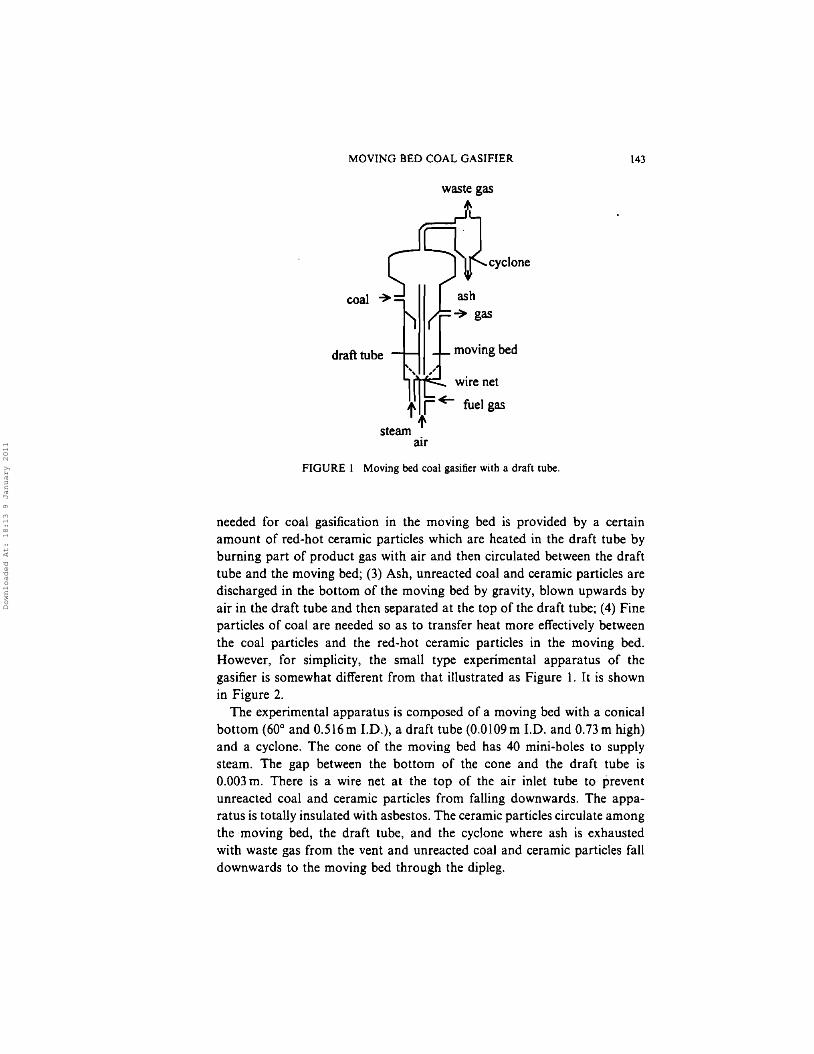
The schematic diagram of the gasifier is illustrated in Figure 1. The gasifierhas the following characteristics: (1) The endothermic process of coalgasification in the moving bed (gasification zone) is separated from theheat providing process of combustion in the draft tube, so that a gas ofhigher calorific value can be obtained in the moving bed; (2) The heat
Downloaded At: 18:13 9 January 2011
MOVING BED COAL GASIFIER 143
waste gas
cyclone
wire net
moving bed
ash
~ gas
t r +- fuel gas
steam Itair
draft tube
FIGURE 1 Moving bed coal gasifier with a draft tube.
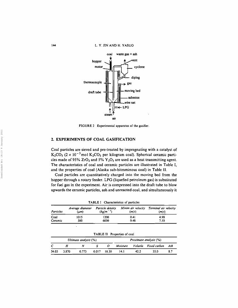
needed for coal gasification in the moving bed is provided by a certainamount of red-hot ceramic particles which are heated in the draft tube byburning part of product gas with air and then circulated between the drafttube and the moving bed; (3) Ash, unreacted coal and ceramic particles aredischarged in the bottom of the moving bed by gravity, blown upwards byair in the draft tube and then separated at the top of the draft tube; (4) Fineparticles of coal are needed so as to transfer heat more effectively betweenthe coal particles and the red-hot ceramic particles in the moving bed.However, for simplicity, the small type experimental apparatus of thegasifier is somewhat different from that illustrated as Figure 1. It is shownin Figure 2.
The experimental apparatus is composed of a moving bed with a conicalbottom (600 and 0.516m 1.0.), a draft tube (0.0109m LD. and O.73m high)and a cyclone. The cone of the moving bed has 40 mini-boles to supplysteam. The gap between the bottom of the cone and the draft tube is0.003 m. There is a wire net at the top of the air inlet tube to preventunreacted coal and ceramic particles from falling downwards. The apparatus is totally insulated with asbestos. The ceramic particles circulate amongthe ·moving bed, the draft tube, and the cycJone where ash is exhaustedwith waste gas from the vent and unreacted coal and ceramic particles falldownwards to the moving bed through the dipleg.
Downloaded At: 18:13 9 January 2011
144 L. Y. JIN AND H. YASUO
hopper
motor
thermocouple
draft tube
wastegas + ash
ent
cyclone
dipleg
~ gas
~mOVing bed
I", / .asbestos
t~r- L;~re net
steamtair
FIGURE 2 Experimental apparatus of the gasifier.
2. EXPERIMENTS OF COAL GASIFICATION
Coal particles are sieved and pre-treated by impregnating with a catalyst ofKiC03 (2 x lO-3 mol K2C03 per kilogram coal). Spherical ceramic particles made of 95% Zr02 and 50/0 Y203 are used as a heat transmitting agent.The characteristics of coal and ceramic particles are illustrated in Table I,and the properties of coal (Alaska sub-bitmminous coal) in Table II.
Coal particles are quantitatively charged into the moving bed from thehopper through a rotary feeder. LPG (liquefied petroleum gas) is substitutedfor fuel gas in the experiment. Airis compressed into the draft tube to blowupwards the ceramic particles, ash and unreacted coal, and simultaneously it
TABLE I Characteristics of particles
Particles
CoalCeramic
A verage diameter(JJI11)
1015SOO
Particle density(kg/m- 3
)
12006000
Minim air velocity(mls)
0.410.48
Terminal air velocity(mls)
4.907.10
TABLE II Properties of coal
Ultimate analysis (0/0) Proximate analysis (%)
C H N S 0 Moisture Volatile Fixed carbon Ash
54.03 3.870 0.773 0.017 18.30 14.1 42.2 35.0 8.7
Downloaded At: 18:13 9 January 2011
MOVING BED COAL GASIFIER
TABLE III Experimental operating conditions
145
Feed rate Feed rate Feed rateof coal of steam ofair(kgjs) (kgjs) (m3js)
0.16 X 10- 3 2.20 X 10- 4 7.82 X 10- 4
Feed rateof LPG(m3js)
2.23 x 10-~
Circulating rateof ceramic particles
(kg/s)
S X 10- 3
Reactiontemperature
(OC)
800
TABLE IV Experimental results of coal gasification
Producing rateCarbon conversion (%) ofgas (m3js) Gas composition (%)
98 4.71 x 10- 4 CO CO2 H2 ca, H2024.0 14.0 44.8 0.2 17.0
is used as the oxidizer for combustion with LPG. The temperature of themoving bed is measured by a thermocouple. Gas composition is analyzedby GC-8A SHIMADZU gas chromatography. The experimental operatingconditions and the obtained experimental results are respectively illustratedin Tables III and IV.
3. THERMODYNAMIC CALCULATION MODEL
3.1. Some Hypotheses and Explanations
In order to make it possible to carry out thermodynamic calculation of thegasifier and the directly-buming-coal-gasifier, some hypotheses and explanations about the process of coal gasification must be made as follows:
(I) Generally speaking, in the process of coal gasification of the gasifier,there are six main components (C, H20, CO, CO2, H2 and CH 4) whichinclude three elements (C, Hand 0). Hence, there are three independentreactions that must be taken into account to make the mass balance ofthe gasifier. Here, the coal gasifying reaction, the shifting reaction andthe methanation reaction are selected as the independent reactions:
(1)
(2)
(3)
Equations (1)-(3) are reversible and supposed to reach their reactionequilibrium states respectively in the process of coal gasification so as tomeet the requirement of the reaction calculation.
Downloaded At: 18:13 9 January 2011
146 L. Y. lIN AND H. YASUO
(2) Similarly, for the directly-buming-coal-gasifier, there are eight maincomponents C, H 20, CO, CO 2, H2, 02, N2 and CH4 in the process ofcoal gasification. And these components include four elements C, H, °and N. Hence, there are four independent reactions, three of which arethe same as the above Eqs. (1)-(3) and one is the burning reaction ofcarbon with oxygen:
(4)
(3) According to Eqs. (1)-(3), produced gas of the gasifier is considered asthe mixture of CO, CO 2, H2, CH4 and H20. Hence, the burning reactions of fuel gas with air are expressed as follows:
(5)
(6)
(7)
All the above burning reactions with oxygen expressed in Eqs. (4) - (7)are irreversible.
(4) In coal gasification experiment of the gasifier, the mass ratio of steam tocoal is 1.38 which just makes the reaction temperature in the movingbed stay around 800°C. In addition, the ratio of air to coal is takenas 4.89 m3/kg. In such condition, air can provide enough oxygen forcombustion and blow upwards the ceramic particles in the draft tube.Hence, for the sake of comparison, the same ratios of steam/coal andair/coal are employed in the thermodynamic calculation of the gasifier.While in the simulating calculation, the ratios are changed.
(5) For the gasifier, the temperature difference between the product gas andthe partly circulated gas for combustion is not considered.
(6) Both types of coal gasifiers are adiabatic.(7) Compared with the chemical available energy of coal, steam, gas or
waste gas, the available energy of air and the Physical available energyof coal in atmospheric state are neglected.
3.2. Calculating Diagrams
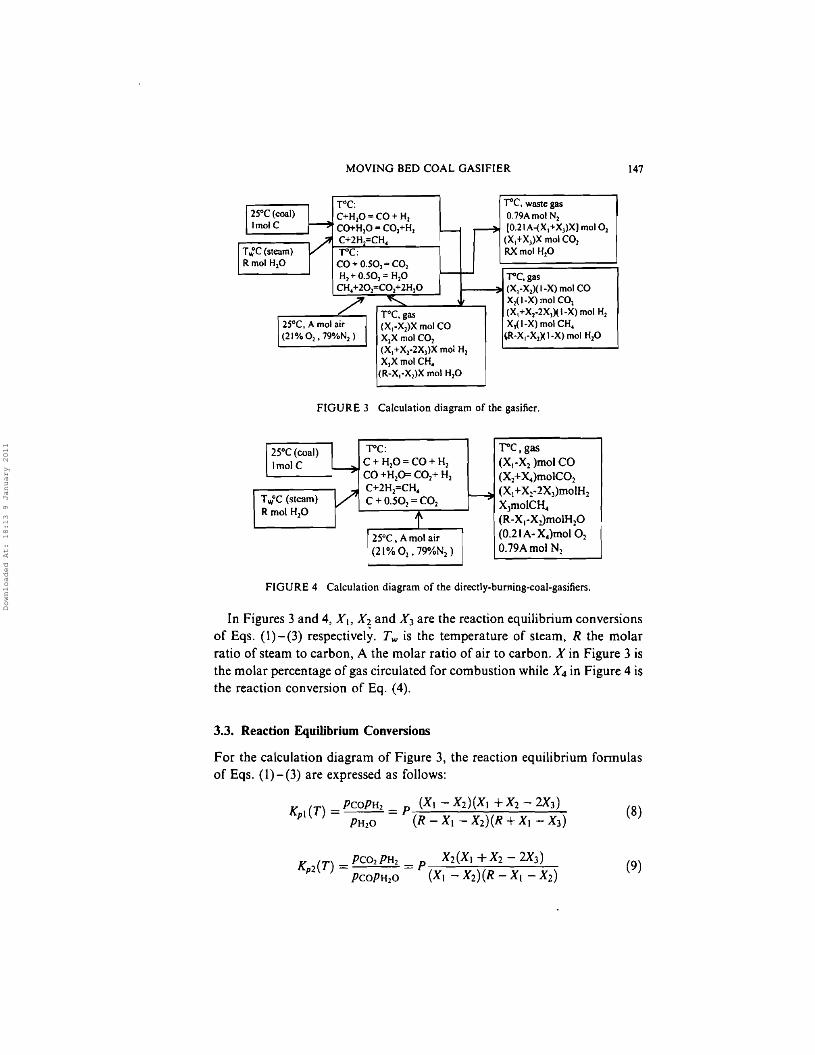
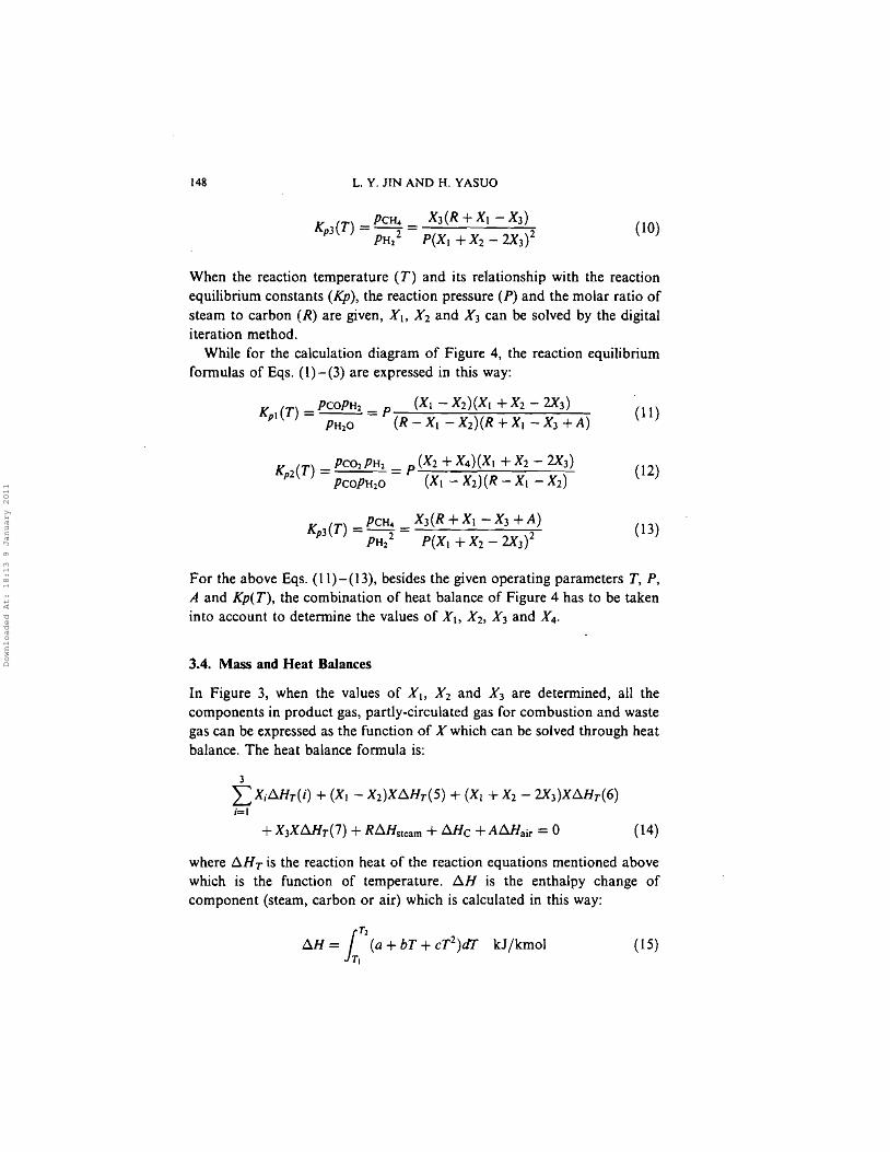
Based on Figure 2 and the above mentioned hypotheses, the thermodynamiccalculating diagram of the gasifier is illustrated in Figure 3. Meanwhile, inorder to compare the gasifier with the directly-burning-coal-gasifier, thethermodynamic calculation diagram of the latter is illustrated in Figure 4.
Downloaded At: 18:13 9 January 2011
MOVING BED COAL GASIFIER 147
TOC:C+H,O=CO+ H,CO+H,O =CO~+H2
C+2H =CH4
--roc:co + 0.502 "" CO2
H2 +0.50, =H20
CH4+202=CO,+2H20
T'C, waste gasO.79AmolN~(O.2JA-(X,+X) X) mol O2
(X.+X3)X mol CO2
RXmol H~O
-roc. gasI---~ (X1-X2) ( I-X) mol CO
Xz(I-X)mol CO2
(X 1+X,.2Xl)(I-X) mol H,X)(I-X) mol CH4
~-XI-Xl)( I·X) mol H,O
TOC. gas(X,.X2)X mol COX1X mol CO2(X1+X,·2X)X mol H2
X)XmoICH..(R-X,-X2)X mol H20
2SDC, A mol air(21% °2 , 79%N2 )
FIGURE 3 Calculation diagram of the gasifier.
Twoe (steam)Rmol H20
r-c:C + H,O=CO+ H2
CO +H20= CO,+ H2
C+2H2=CH.
C + 0.502 = CO2
r-c, gas(XI-X2 )mol CO(X2+~)moIC02(X,+Xz-2X3)moIH2
XJmolClL(R-X,-XJmolH20
(O.21A- X4)mol O2
O.19Amol N2
FIGURE 4 Calculation diagram of the directly-burning-coal-gasifiers.
In Figures 3 and 4, X., X2 and %3 are the reaction equilibrium conversionsof Eqs. (1)-(3) respectively. T; is the temperature of steam, R the molarratio of steam to carbon, A the molar ratio of air to carbon. X in Figure 3 isthe molar percentage of gas circulated for combustion while X4 in Figure 4 isthe reaction conversion of Eq. (4).
(8)
3.3. Reaction Equilibrium Conversions
For the calculation diagram of Figure 3, the reaction equilibrium formulasof Eqs. (1)-(3) are expressed as follows:
Kpl (T) = PCOPH2 = P (Xl - X2)(XI + X2 - 2X3 )
PH 20 (R - XI - X2)(R + XI - X3)
(9)
Downloaded At: 18:13 9 January 2011
148 L. Y. JIN AND H. YASUO
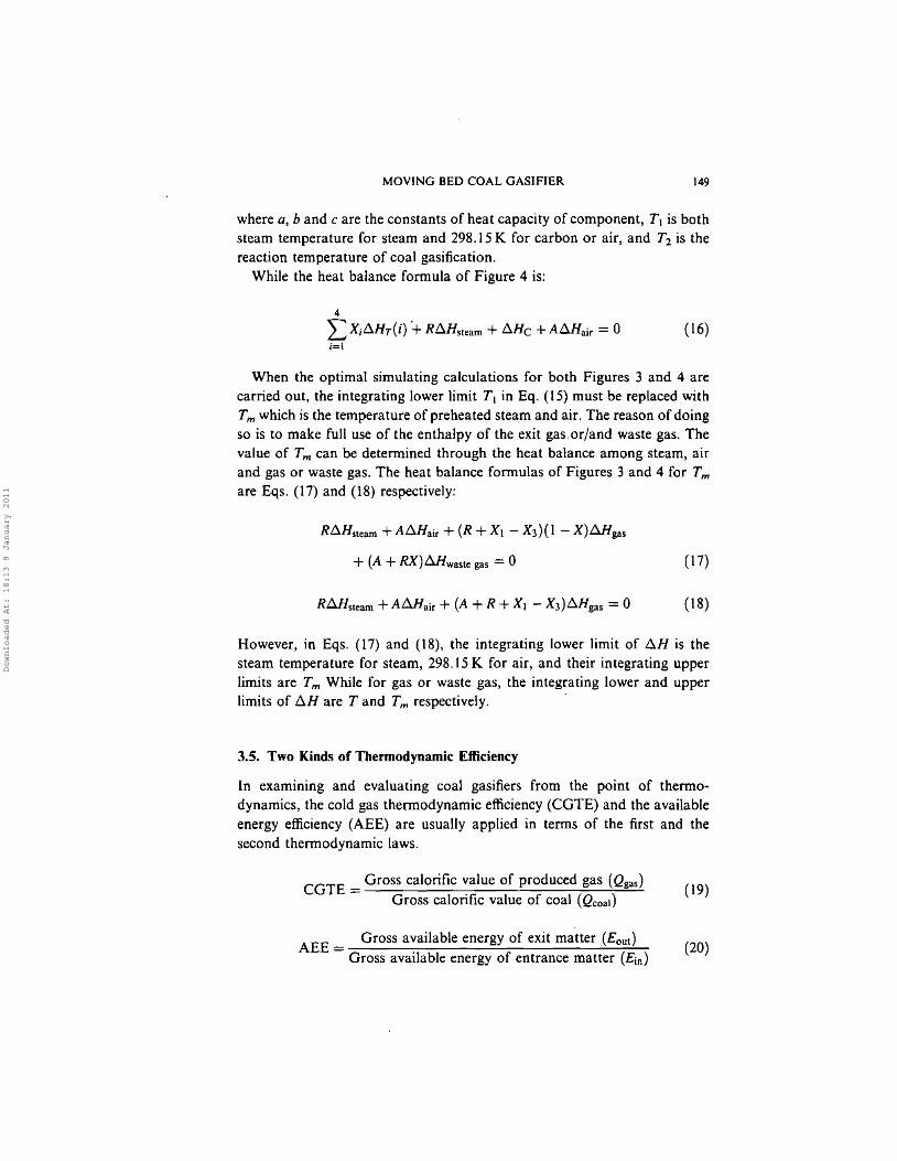
(10)
(11)
When the reaction temperature (T) and its relationship with the reactionequilibrium constants (Kp), the reaction pressure (P) and the molar ratio ofsteam to carbon (R) are given, XI, X2 and X3 can be solved by the digitaliteration method.
While for the calculation diagram of Figure 4, the reaction equilibriumformulas of Eqs. (1) - (3) are expressed in this way:
Kp l
(T) =PCOPH 2 = P (Xl - X2)(Xl + Xl - 2X3)PH2 0 (R - XI - X2)(R + XI - X3 +A)
(12)
(13)
For the above Eqs. (11)-(13), besides the given operating parameters T, P,A and Kp( T), the combination of heat balance of Figure 4 has to be takeninto account to determine the values of X., X2 , X 3 and X4 .
3.4. Mass and Heat Balances
In Figure 3, when the values of Xl, X 2 and X3 are determined, all thecomponents in product gas, partly-circulated gas for combustion and wastegas can be expressed as the function of X which can be solved through heatbalance. The heat balance formula is:
3
L,XiLlHr(i) + (Xl - X2)X6.Hr (5) + (Xl + X2 - 2X3)X6.Hr(6);=1
(14)
where 6.HT is the reaction heat of the reaction equations mentioned abovewhich is the function of temperature. f!,.H is the enthalpy change ofcomponent (steam, carbon or air) which is calculated in this way:
( 15)
Downloaded At: 18:13 9 January 2011
MOVING BED COAL GASIFIER 149
where a, band c are the constants of heat capacity of component, T 1 is bothsteam temperature for steam and 298.15 K for carbon or air, and T2 is thereaction temperature of coal gasification.
While the heat balance formula of Figure 4 is:
4
L XiLlHT(i) '+ RLlHsteam + 6.Hc + ALVfair = 0 (16)i=1
When the optimal simulating calculations for both Figures 3 and 4 arecarried out, the integrating lower limit T 1 in Eq. (15) must be replaced withTm which is the temperature of preheated steam and air. The reason of doingso is to make full use of the enthalpy of the exit gas. or/and waste gas. Thevalue of Tm can be determined through the heat balance among steam, airand gas or waste gas. The heat balance formulas of Figures 3 and 4 for Tm
are Eqs. (17) and (18) respectively:
RD.Hsteam + AD.Hair + (R+ Xl - X3)(1 - X)1lHgas
+ (A + RX)LlHwaste gas = 0 (17)
RilHsteam + ALlHair + (A + R + Xl - X3)LlHgas = 0 (18)
However, in Eqs. (17) and (18), the integrating lower limit of D.H is thesteam temperature for steam, 298.15 K for air, and their integrating upperlimits are Tm While for gas or waste gas, the integrating lower and upperlimits of LlH are T and Tm respectively. .
3.5. Two Kinds of Thermodynamic Efficiency
In examining and evaluating coal gasifiers from the point of thermodynamics, the cold gas thermodynamic efficiency (CGTE) and the availableenergy efficiency (AEE) are usually applied in terms of the first and thesecond thermodynamic laws.
CGTE = Gross calorific value of produced gas (Qgas) (19)Gross calorific value of coal (Qcoal)
AEE = Gross available energy of exit matter (Eout ) (20)Gross available energy of entrance matter (Ein)
Downloaded At: 18:13 9 January 2011
150 L. Y. JlN AND H. .YASUO
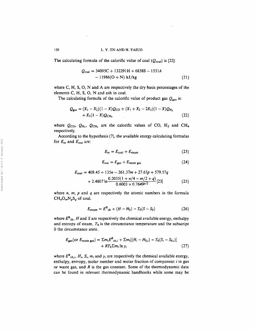
The calculating formula of the calorific value of coal (Qcoal) is [22]:
Qcoal = 34095C + 132291H + 6838S - 1531A
- 11986(0 + N) kJ/kg (21)
where C, H, S, 0, N and A are respectively the dry basis percentages of theelements C, H, S, 0, N and ash in coal.
The calculating formula of the calorific value of product gas Qgas is:
Qgas = (Xl - X2)( I - X)Qco + (Xl + X2 - 2X3)(1 - X)QH2
+ X3( 1 - X)QCH. (22)
where Qco, QH2 , QCH.. are the calorific values of CO, H2 and CH4
respectively.According to the hypothesis (7), the available energy calculating formulas
for Ein and E~ut are:
e; = Ecoal + Esteam
Eout = Egas + Ewaste gas
Ecoal = 408.45 + 135n - 261.37m + 27.63p + 579.57q
2 48071 O.2035(1 + n/4 - m/2 + q) [23]+. n 0.6003 x O.7649p/2
(23)
(24)
(25)
where n, m, p and q are respectively the atomic numbers in the formulaCHnOmNpSq of coal.
Esteam = EBch + (H - Ho) - To(S - So) (26)
where EBch- Hand S are respectively the chemical available energy, enthalpyand entropy of steam, To is the circumstance temperature and the subscriptothe circumstance state.
Egas(or Ewaste gas) = 'Em;EBch,; + ~mi[(Hi - HO,i) - TO(Si - SO,i)]
+ RToEm; ln y, (27)
where EBch,i, H;, S,., m, and Yi are respectively the chemical available energy,enthalpy, entropy, molar number and molar fraction of component i in gasor waste gas, and R is the gas constant. Some of the thermodynamic datacan be found in relevant thermodynamic handbooks while some may be
Downloaded At: 18:13 9 January 2011
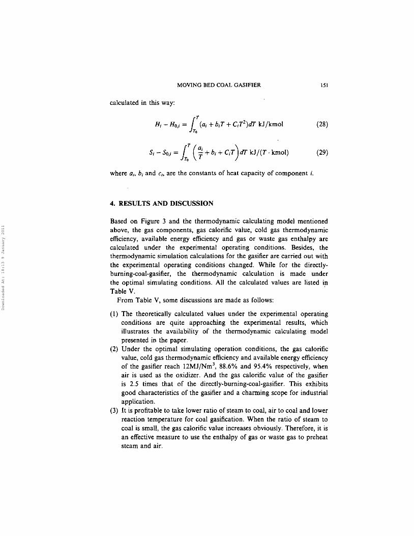
calculated in this way:
MOVING BED COAL GASIFIER lSI
n, - Ho,; =I T
(Q; +b;T + C;T2)ar kJjkmol (28)To
where a.. b, and c.; are the constants of heat capacity of component i.
4. RESULTS AND DISCUSSION
Based on Figure 3 and the thermodynamic calculating model mentionedabove, the gas components, gas calorific value, cold gas thermodynamicefficiency, available energy efficiency and gas or waste gas enthalpy arecalculated under the experimental operating conditions. Besides, thethermodynamic simulation calculations for the gasifier are carried out withthe experimental operating conditions changed. While for the directlyburning-coal-gasifier, the thermodynamic calculation is made underthe optima] simulating conditions. All the calculated values are listed inTable V.
From Table V, some discussions are made as follows:
(1) The theoretically calculated values under the experimental operatingconditions are quite approaching the experimental results, whichillustrates the availability of the thermodynamic calculating modelpresented in the paper.
(2) Under the optimal simulating operation conditions, the gas calorificvalue, cold gas thermodynamic efficiency and available energy efficiencyof the gasifier reach 12MJ/Nm3
, 88.6% and 95.40/0 respectively, whenair is used as the oxidizer. And the gas calorific value of the gasifieris 2.5 times that of the directJy-burning-coal-gasifier. This exhibitsgood characteristics of the gasifier and a charming scope for industrialapplication.
(3) It is profitable to take lower ratio of steam to coal, air to coal and lowerreaction temperature for coal gasification. When the ratio of steam tocoal is small, the gas calorific value increases obviously. Therefore, it isan effective measure to use the enthalpy of gas or waste gas to preheatsteam and air.
Downloaded At: 18:13 9 January 2011
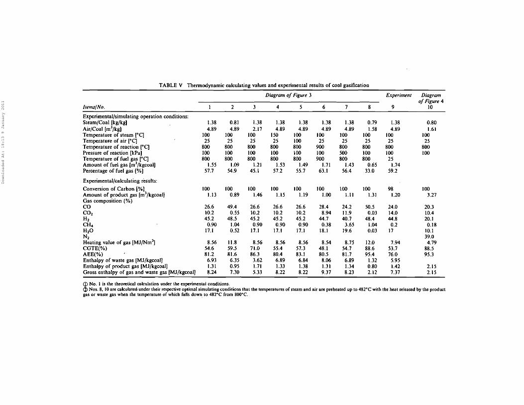
TABLE V Thermodynamic calculating values and experimental results of coal gasification
Diagram of Figure 3 Experiment Diagramof Figure 4
ItemslNo, 1 2 3 4 5 6 7 8 9 10
Experimental/simulating operation conditions:Steam/Coal [kg/kg] 1.38 0.81 1.38 1.38 1.38 1.38 1.38 0.79 1.38 0.80Air/Coal [mJ/kg] 4.89 4.89 2.17 4.89 4.89 4.89 4.89 1.58 4.89 1.61Temperature of steam [oq 100 100 100 150 100 100 100 100 foo 100Temperature of air [0C] 25 25 25 25 100 25 25 25 25 25Temperature of reaction [0C] 800 800 800 800 800 900 800 800 800 800Pressure of reaction [kPa) 100 100 100 100 100 100 500 100 100 100Temperature of fuel gas [DC] 800 800 800 800 800 900 800 800 25Amount of fuel gas [m3/kgcoal) 1.55 1.09 1.21 1.53 1.49 1.71 1.43 0.65 1.74Percentage of fuel gas (%) 57.7 54.9 45.1 57.2 55.7 63.1 56.4 33.0 59.2
Experimental/calculating results:
Conversion of Carbon [%] 100 100 100 100 100 100 100 100 98 100Amount of product gas [m3/kgcoalj 1.13 0.89 1.46 1.15 1.19 1.00 1.11 1.31 1.20 3.27Gas composition (%)CO 26.6 49.4 26.6 26.6 26.6 28.4 24.2 50.5 24.0 20.3CO 2 10.2 0.55 10.2 10.2 10.2 8.94 11.9 0.03 14.0 10.4H2 45.2 48.5 45.2 45.2 45.2 44.7 40.7 48.4 44.8 20.1CH 4 0.90 1.04 0.90 0.90 0.90 0.38 3.65 1.04 0.2 0.18H2O 17.1 0.52 17.1 17.1 17.1 18.1 19.6 0.03 17 10.1Nz 39.0Heating value of gas [MJfNm3
] 8.56 11.8 8.56 8.56 8.56 8.54 8.75 12.0 7.94 4.79CGTE(%) 54.6 59.5 71.0 55.4 57.3 48.1 54.7 88.6 53.7 88.5AEE(%) 81.2 81.6 86.3 80.4 83.1 80.5 81.7 95.4 76.0 95.3Enthalpy of waste gas (MJ/kgcoaJ] 6.93 6.35 3.62 6.89 6.84 8.06 6.89 1.32 5.95Enthalpy of product gas [MJ/kgcoal] 1.31 0.95 1.71 1.33 1.38 1.31 1.34 0.80 1.42 2.15Gross enthalpy of gas and waste gas (MJ/kgcoal] 8.24 7.30 5.33 8.22 8.22 9.37 8.23 2.12 7.37 2.15
CD No. I is the theoretical calculation under the experimental conditions.(%) Nos. 8, 10 arc calculated under their respective optimal simulating conditions that the temperatures of steam and air arc preheated up to 482"C with the heat released by the productgas or waste gas when the temperature of which falls down. to 482"C from 800°C.
Downloaded At: 18:13 9 January 2011
5. CONCLUSION
MOVING BED COAL GASIFIER 153
The coal gasification experiment and thermodynamic calculation of thenewly developed moving bed coal gasifier with a draft tube are doneaccording to the thermodynamic calculating model founded 00 the basis ofchemical reaction equilibrium, mass balance aod heat balance. The obtainedexperimental results are quite approaching to the thermodynamicallycalculated values. The thermodynamic simulating calculations of the gasifierindicate that it is profitable to take lower ratio of steam to coal, air to coaland lower reaction temperature for coal gasification, and it is an effectivemeasure to use the enthalpy of gas or waste gas to preheat air and steam.Under the optimal simulating operation conditions, gas calorific value,cold gas thermodynamic efficiency and available energy efficiency of thegasifier can reach 12 MJfNm3
, 88.6% and 95.40/0 respectively, when air isused as the oxidizer. Compared with the directly-buming-coal-gasifier, thegasifier exhibits good characteristics and a charming scope for industrialapplication. .
References
[I] Chatterjee, P. K., Datta, A. B. and Kundu, K. M. (1995). Can. J. Chern. Eng., 73(2),204-210.
[2] Cheng. H. W., Jin, B. S. and Xu, Y. 1. (1997). 14th Proc. Int. ConI. Fluid Bed Combust,2, 1081-1086.
[3] Iwahara, M. and Yamaguchi, E. (1998). JP 10, 330768.[4] Ikeda, Y. (1998). JP 10, 279960.[5] Hoppesteyn, P. D. J., De Jong, W., Andries, J. et al. (1998). Bioresour. Technol., 65(1-2),
105-115.[6] Fang, Y. T., Zhou, Z., Wang, H. Y. et al. (1997). 14th (P2) Proc.-Annu. Int. Pittsburgh
Coal Conf., pp. 60-67.[7] Ikeda, Y. and Abe, S. (1998). JP 10. 95987.[8] Albrecht, J. and Loeffler. J. (1998). WO 98, 27182.[9] Tsuji. T. and Uemaki, O. (1994). Can. J. Chern. Eng., 72,504-510.
[10] Tokuda, K., Nakajima, F., Furuya, T. et al. (1994). JP 06,330058.[II] Taketa. M., Ueda, A. and Watabe, Y. (1998). JPIO, 237463.[12] Hanson,S., Walker, A. and Patrick, J. W. (1998). I. Chem. E Res. Event; Two-Day Symp.,
pp. 613-621.[13] Arnold, M. ST. J., Gale, J. J. and Laughlin, M. K. (1992). Can. J. Chern. Eng., 70,
991-997.[14] Bi, J., Aoki, K. I. and Luo, C. H. (1997). 14th (S20) Proc-Annu. Int. Pittsburgh Coal
Conf., pp. I - 5.[15] Chen, C., Murayama, Y., Kamiya, H. et al. (1997). 14th (P2) Proc-Annu. Int. Pittsburgh
Coal cs«; pp. 26 - 34.[16] Shimizu, A. (1997). IP 09, 273711.[17] Bryan, B. G. and Hoppe, J. A. (1998). 15th Proc.-Annu. Int. Pittsburgh Coal Conf.,
pp.496-505.[18] Kim, Y. J., Lee, J. M. and Kim, S. D. (1997). Fuel. 76(11), 1067-1073.[19] Lee, J. M., Kim, Y. J., Kim, S. D. (1998). Appl. Therm. Eng., 18(11), 1013-1024.
Downloaded At: 18:13 9 January 2011
154 L. Y. JlN AND H. YASUO
[20] Liu, Y. J., Uemura, Y., Ijichi, K. et al. (1999). Chinese J. of Chern. Eng., 7(2), 178- 181.[21] Van Diepen, A. E. and Moulijn, J. A. (1998). NATO AS] Ser., SeT. G, 42, 57-74.[22] David, M. and Mason, K. N. (1983). Fuel Processing Technology, 7, 11-22.[23] Singh, S. P. (1980). Energy,S, 90S.
Downloaded At: 18:13 9 January 2011