Embed Size (px)
Citation preview

Coal Demand and Supply prospects world-wide & the development of
cleaner technologies
Dr John Topper, Managing DirectorPorto Alegre, Brazilg ,
August, 2011

A source of unbiased information on sustainable use of coal world-wide
Italy Japan
Rep. of Korea S Africa
GermanyCEC
Poland
IEA CCC MEMBERSUK
SpainS Africa
Austria
Canada
IEA CCC MEMBERSAnglo American Thermal Coal
USA
Beijing Research
Australia
GCCSI
Netherlands GroupBeijing ResearchInst Coal Chemistry
Coal Assoc NZEl t bD i h P G
SchlumbergerBanpu
BHEL EletrobrasDanish Power Group
SuekVattenfall

www iea coal org ukwww.iea-coal.org.uk

GLOBAL COAL SUPPLY AND DEMAND TO 2035
Recent policy commitments,if implemented, would make a differenceif implemented, would make a difference
Source IEA World Energy Outlook 2010
World primary energy demand by region in the New Policies Scenariop y gy y g
16 000
18 000
Mto
e
Rest of world
China
12 000
14 000 OCED
WEO-2009:Reference Scenario
6 000
8 000
10 000Reference Scenario
2 000
4 000
6 000
Global energy use grows by 36%, with non-OECD countries – led by China,
01990 1995 2000 2005 2010 2015 2020 2025 2030 2035
Global energy use grows by 36%, with non OECD countries led by China,where demand surges by 75% – accounting for almost all of the increase

Emerging economies dominatethe growth in demand for all fuels
Source: IEA WEO 2010
Incremental primary energy demand in the New Policies Scenario, 2008‐2035p y gy
CoalOECD
China
Gas
Oil Rest of world
Hydro
Nuclear
Other renewables
Hydro
Demand for all types of energy increases in non-OECD countries,
- 600 - 300 0 300 600 900 1 200 1 500
Mtoe
yp gy ,while demand for coal & oil declines in the OECD

Coal remains the backbone of global electricity generation
Source: IEA WEO 2010
Coal‐fired electricity generation by region in the New Policies Scenario
12 000
TWh China
y g y g
8 000
10 000 India
Other non-OECD
OECD
4 000
6 000
OECD
0
2 000
A drop in coal-fired generation in the OECD is offset by big increases elsewhere, especially Chi h 600 GW f it d th t it f th US EU & J
0
1990 2000 2010 2020 2030 2035
China, where 600 GW of new capacity exceeds the current capacity of the US, EU & Japan

Coal Fired Power Stations Today

Recent Plant State-of-the-Art Conditions
Studstrup (DK) 540/540
Maatsura 1 (J) 538/566Maatsura 1 (J) 538/566
Esbjerg (DK) 560/560
Schwarze Pumpe (D) 547/565
Maatsura 2 (J) 593/593600
610
e, °
C
⊗Ultrasupercritical Maatsura 2 (J) 593/593
Haramachi 2 (J) 600/600
Nordjylland (DK) 580/580/580
Bo berg (D) 545/581580
590
empe
ratu
re Ultrasupercritical
Boxberg (D) 545/581
Tachibanawan 1 (J) 600/610
Avedore (DK) 580/600560
570
H S
team
Te
Supercritical
Niederaussem (D) 580/600
Hekinan (J) 568/593
Isogo (J) 600/610Yunghung 566/576540
550
Max
SH
Torrevaldaliga (I) 600/610⊗Hitachinaka (J) 600/600
Genesee 3 580/570Yunghung 566/576
530
540
1980 1985 1990 1995 2000 2005 2010
Huyan (China)Year

Torrevaldaliga Nord
USC, boilers supplied by Babcock Hitachi , i bit i lusing bituminous coal
3 units at 660MWe = 1980MWe stationVery low conventional emissions (NOx <100 mg/m3, sulphur oxides
3 3<100 mg/m3, particulates 15 mg/m3, at 6% O2, dry); full waste utilisation
Highest steam conditions: 604°C/612°C at turbine: 25 MPaOperating net efficiency >44.7% LHV Wet scrubber based limestone/gypsum FGDNOx abatement SCRNOx abatement SCRParticulates removal Bag filtersNew sea port for coal deliverySolids handling all enclosed

Niederaussem K, Germany
USC, tower boiler, tangential wall firing, li it f 50 60% i t i l d
Most efficient lignite-fired plant
lignite of 50-60% moisture, inland
Operating net efficiency 43.2% LHV/37% HHV High steam conditions 27.5 MPa/580°C/600°C at turbine; initial
difficulties solved using 27% Cr materials in critical areasgUnique heat recovery arrangements with heat extraction to low
temperatures – complex feedwater circuitLow backpressure: 200 m cooling tower 14 7°C condenser inletLow backpressure: 200 m cooling tower, 14.7 C condenser inletLignite drying demonstration plant being installed to process 25%
of fuel feed to enable even higher efficiencyNO b t t C b ti NOx abatement Combustion measuresParticulates removal ESPDesulphurisation Wet FGD

Isogo New Unit 1, Japan
USC, tower boiler, opposed wall firing, int bit d J l tbitum and Japanese coals, warm sea water
Near zero conventional emissions (NOx 20 mg/m3, sulphur oxides 6 mg/m3, particulates 1 mg/m3, at 6% O2, dry); full waste utilisation
Highest steam conditions: 25.0 MPa/600°C/610°C at turbine: ASME CC 2328 steels in S/H; P122 for main steam pipework
Operating net efficiency >42% LHV/40.6% HHVEfficiency tempered slightly by 21°C CW, fewer FW heating stages Dry regenerable activated coke FGD (ReACT)NOx abatement Combustion measures and SCRNOx abatement Combustion measures and SCRParticulates removal ESPIsogo New Unit 2 will use ReACT specifically for multi-pollutant
t l i l di control, including mercury

Status of USC boilers ordered by end of May 2008:China now leads the world in Supercritical Boiler
installations
Supplier 1000 MWe 660 MWe 600 MWe
No Capacity, No Capacity, No Capacity,GWe GWe GWe
Harbin 16 16.0 18 11.9 10 6.0
Shanghai 36 36.0 16 10.6
Dongfang 28 28.0 10 6.6
Beijing B&W 4 4.0 2 1.3 4 2.4
Sub-total 84 84.0 46 30.4 14 8.4

Source: Powerline, Feb 2008
© IEA Clean Coal Centre www.iea-coal.org.uk

High Efficiency, Low Emissions Coal Technology Status Today (1)Technology Status Today (1)
Pulverised coal combustion
~Hundreds of GWe installed, units to ~1000 MWe
Efficiency to upper 40s% (LHV) in best locations
Mill
Efficiency to upper 40s% (LHV) in best locations
Conventional emissions control well established
How will it be in 10 or 20 years?Mills
AshCoal
SCRFlue gas
y
Still the most deployed coal technology
Advanced emissions control, including dry systems
Limestone slurry
Air heater
Ai
AshStackIncremental efficiency improvements
Further efficiency gains from novel lignite drying and from jump to 35 MPa/700˚C steam slurry
Gypsum
Air FGDj p /
CCS as integrated technology using flue gas scrubbing or oxygen firing

50% efficient plantp
… 50 plus by using new nickel alloy superheater tubing at 700C
LocationEffi i
Wilhelmshaven0 %Efficiency
Capacity
50 %
500 MWe
Postponed/Cancelled in 2010
Will this ever be reinstated?What are the prospects for solving welding and heat
treatment issues?treatment issues?Does it look just too expensive for the efficiency gain?

High Efficiency, Low Emissions Coal Technology Status Today (2)
Circulating fluidised bed combustion
Hundreds of units, experience to 460MWe
Suited to low quality coals and other fuels
Emissions control systems well established
How will it be in 10 or 20 years?
Still important, probably burning even more biomass and wastes
Further incremental efficiency improvements
Higher steam conditions (460 MWe S/C unit now g ( /operating in Poland – full load achieved Mar 2009)
CCS using flue gas scrubbing, oxygen firing or, in new designs, chemical looping

Lagisza Supercritical CFBC – new design
The world’s first CFBC unit with supercritical steam conditions
Largest CFBC; 460 MWe
First electricity in First electricity in February 2009
E i i f SO NO Emissions of SOx, NOx and particulates lower than required by latest EU LCPD limitsEU LCPD limits.
Located to NE of K t i P l dKatowice, Poland

High Efficiency, Low Emissions Coal Technology Status Today (3)gy y ( )
Integrated gasification combined cycle (IGCC)
Commercial demonstrations in USA and Europe and Japan. Shortly in China, another in USA. Others at FEED stage
Cost and availability concerns have held back orders inCoal and oxygen RawCost and availability concerns have held back orders in
past
Efficiency ~43‐45% LHVGasification
yg Raw gas
By-products and wastesGas
cleaning
Very low emissions, mercury capture simple
How will it be in 10 or 20 years?
More widely deployed
Clean fuel gas Waste heat
boiler
StackSlag
More widely deployed
Advancing performance and perhaps reducing cost differential with PCC
GAbove from more advanced gas turbines and new gasifierdesigns, dry gas cleaning
Polygeneration
~Gas turbine
Steamturbine ~
Air
CCS using pre‐combustion capture
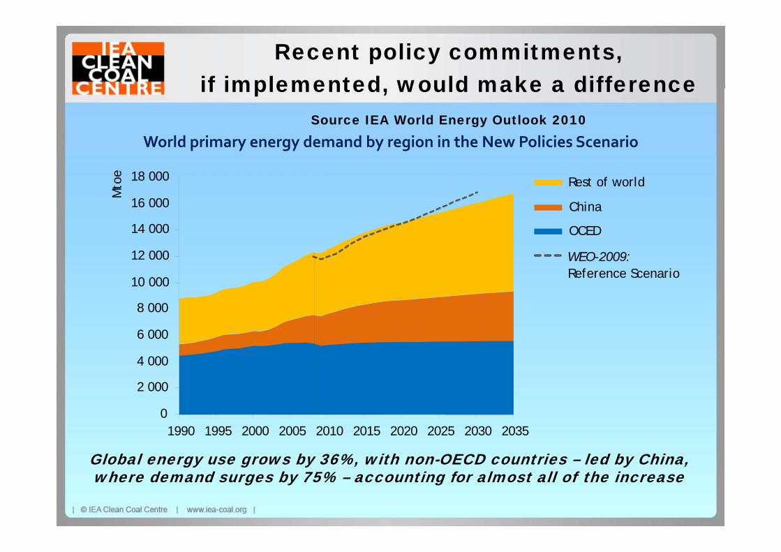
PSE-CO2 project : CO2 Capture Pilot Plant
Puertollano IGCC power plant and pilot plant location
PRENFLO Gasifier
Coal preparation ASU
Sulphur Recovery
Combined Cycle
New CO2capture pilot Recovery ycapture pilot
plant
Pilot plant general view
IGCC power plant general viewCourtesy of Elcogas

Coal Conversion to Liquids or Gas q

Direct Coal Conversion to Liquid Fuels
Methane& Ethane
H2S, NH3, COx
Recycled H2Make-up Gas RecoveryTreatment LPG
& EthaneRecycled H2Make upH2
RefiningHydro-treating
Unit
Coalconversion Diesel Fuel
Gasoline
H D
Coal +Catalyst
Fractionation Heavy Vacuum
H-DonorSlurry
Slurry Fractionation Heavy VacuumGas Oil
SolventDeashing
Ash RejectDeashed Oil Gasifier
Unconverted Coal
Daniel Cicero, International Energy Agency, CIAB Workshop Nov 2, 2006

Indirect Coal Conversion Coal
Oxygen/Steam
CoalPetcoke
Biomassetc Catalyst
Gasification & Fischer-Tropsch FT ProductH2 + CO CxHyLi idGas Cleaning
Fischer TropschSynthesis Separation &
Upgrading
2Syngas Liquids
& Wax
Sulfur,CO2
and Ash
Steam Tail GasWater
&Oxygenates
Ultra-CleanLiquid Fuels& Chemical
Electric PowerGeneration
Steam
ygFeedstocks
Electricity
Daniel Cicero, International Energy Agency, CIAB Workshop Nov 2, 2006
y

IEA CCC Report - CCC/151 by Gordon Couchby Gordon Couch
This recently published report on UCG covers
What UCG involves
The technologies applicable
UCG potential
Trials and prospective developments
Geological and environmental issuesGeological and environmental issues
Syngas use
Conclusions
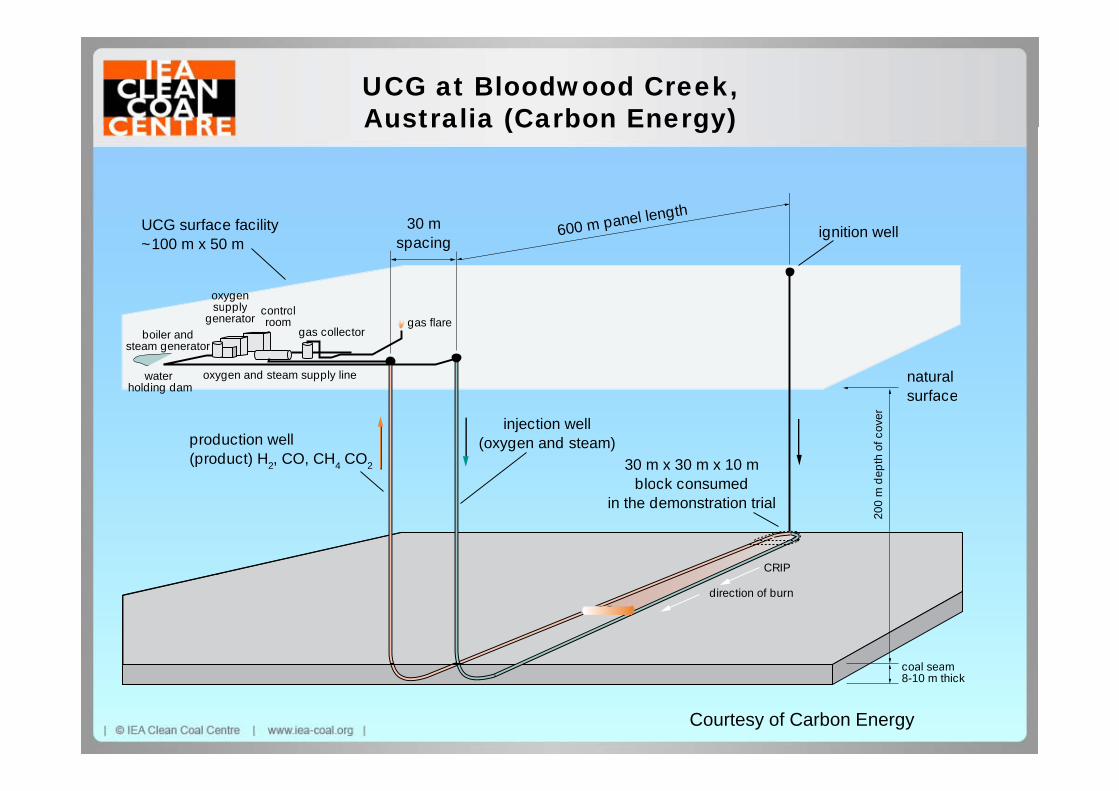
UCG at Bloodwood Creek, Australia (Carbon Energy)
nel length
Australia (Carbon Energy)
UCG surface facility~100 m x 50 m
30 mspacing
600 m panel lengtignition well
oxygensupply
naturalsurface
supplygenerator
controlroom
gas collector
oxygen and steam supply line
boiler andsteam generator
waterholding dam
gas flare
surface
30 m x 30 m x 10 mblock consumed
injection well(oxygen and steam)production well
(product) H2, CO, CH4 CO2
dept
hof
cove
r
block consumedin the demonstration trial
200
m
CRIP
coal seam
direction of burn
coal seam8-10 m thick
Courtesy of Carbon Energy
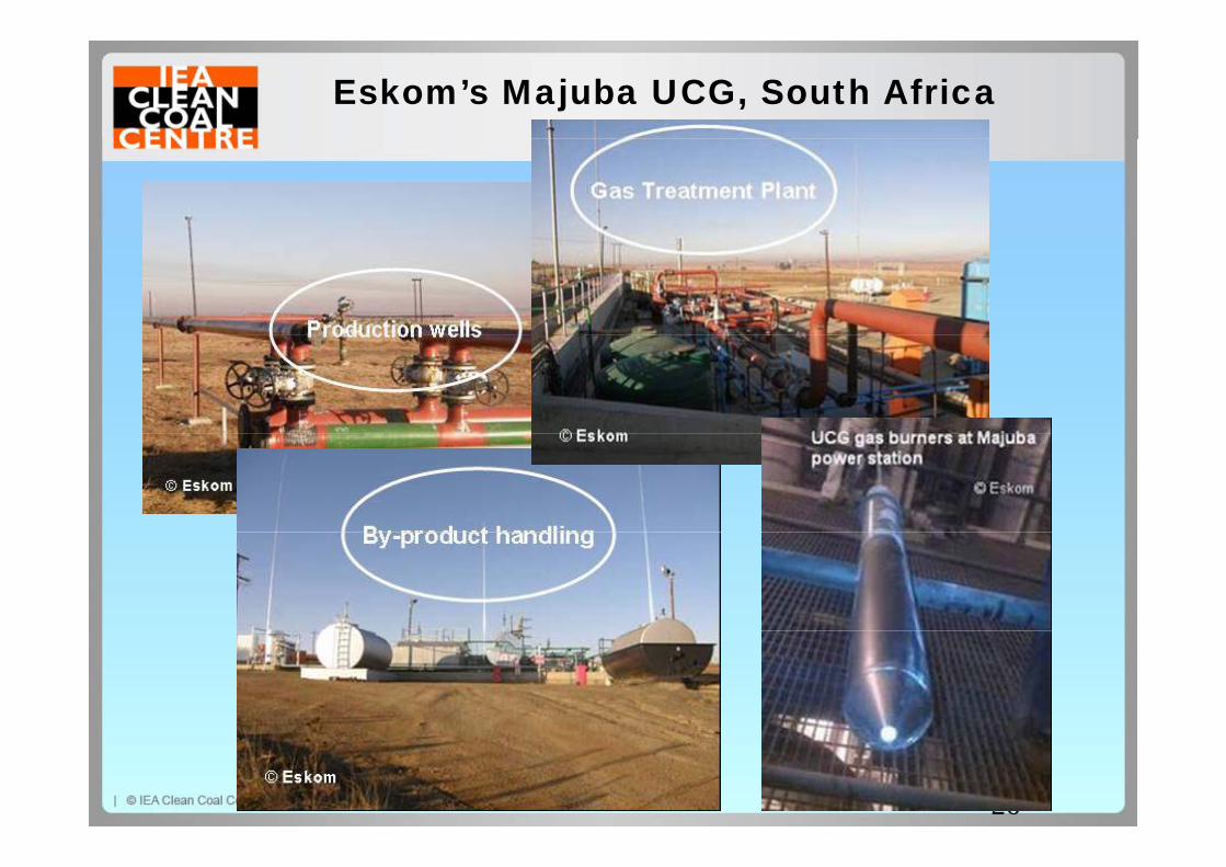
Eskom’s Majuba UCG, South Africa
26

Eskom UCG Development Plan
20th January 2007 28th October 2010
2002
Scoping Study
2003
Pre-feasibilityStudy
2005
Site Characterisation
Commissioned 5000 Nm3/h pilot
plant on Majuba
lfi ld
DoneCommissioned
15000 Nm3/h co-firing into Majuba
power stationcoalfield
Apr 2009 Dec 2011 Sep 2015Mar 2015 Mar 2020 Sep 2022
Provisional Future Dates
Current CommissionC t tiDesign
Demonstration Plant
To do
Current
U2C
U3Comm
U4Comm
U5C
U6Comm
Commission
U1CommConstructionDesign
ConstructionDesign
2100MW 1st Proof-of-Concept Plant
To do Comm Comm Comm Comm CommCommConstructionDesign
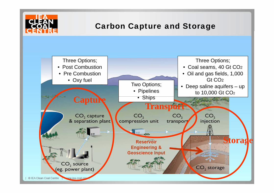
Carbon Capture and Storage
Three Options;• Post Combustion• Pre Combustion
Three Options;• Coal seams, 40 Gt CO2
• Oil and gas fields 1 000
C
Pre Combustion• Oxy fuel
Two Options;• Pipelines
Ships
Oil and gas fields, 1,000 Gt CO2
• Deep saline aquifers – up to 10,000 Gt CO2
CaptureTransport
• Ships
StorageStorage

The ETP BLUE Map Scenario
© OECD/IEA 2009

CCS deployment in the BLUE Map Scenario
er o
f ct
s
2/ye
ar
ture
d
Num
beP
roje
MtC
O2
Cap
t
There is an ambitious growth path for CCS from 2010 to 2050

IEA CCS Roadmap Demonstration to Commercial (2009)Commercial (2009)
Expanded collaboration on ts
CCS R&D and technology
transfer will be iti l p
roje
ct
critical
w b
uild
N
ew

IEA CCS Roadmap is not just about Coal for Powerfor Power
Coal power only makes up around makes up around
40% of stored emissions in 2050

Status of CCS – LSIPs Large Scale Integrated Projects Integrated Projects
Annex C tables LSIP j t it i & d t ilproject criteria & details
67 LSIPs active
Over half with EOR or gas/oil field storage
About half related to coal About half related to coal fired power
All the coal projects are p jin development
About 40% of all projects i USAin USA
Over 20 cancelled LSIPs listedlisted

Vattenfall’s 30MWth oxy fuel pilot plant at Schwarze PumpeSchwarze Pumpe
Operating almost 3 p gyears
Collected good data Collected good data on boiler, CO2 clean
up etc

2nd International Oxyfuel Combustion Conference12th 16th September 201112th – 16th September 2011Capricorn Resort, Yeppoon, Australia
Includes visit to Callide 30MWe oxy fuel retrofitIncludes visit to Callide 30MWe oxy fuel retrofit

Huaneng Group: leaders in post combustion capture in Chinacapture in China
120,000 CO2 tonnes/year t it i Sh h i 2010
3000 CO2 tonnes/year industrial pilot in Beijing 2008 capture unit in Shanghai, 2010industrial pilot in Beijing, 2008

Boundary Dam, SaskPower post combustion test facilityfacility
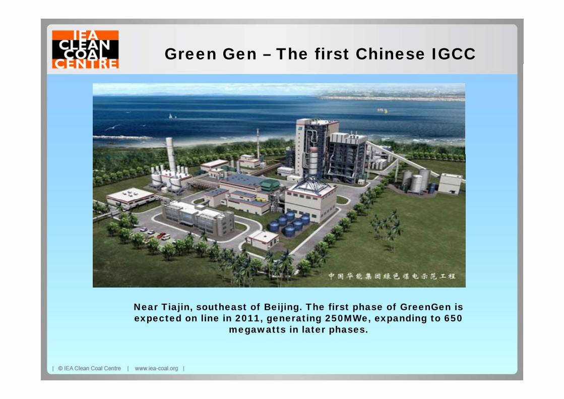
Green Gen – The first Chinese IGCC
Near Tiajin, southeast of Beijing. The first phase of GreenGen is expected on line in 2011, generating 250MWe, expanding to 650
megawatts in later phases.

FINALLY – ARE WE MAKING PROGRESS?2007 2009 20112007 2009 2011
Grandchildren to have electricity from coal through their lifetime
Grandchildren to have electricity from coal through their lifetime
Grandchildren to have electricity from coal through their lifetime their lifetime
Coal can be part of the portfolio of solutions to climate protection
their lifetime
Coal with CCS is indispensable in next decades
their lifetime
Coal with CCS is indispensable in next decadesclimate protection
No single winning clean coal technology, but R & D worldwide is based on a
decades
Still no single winning clean coal technology. Research on 2nd generation
decades
Still no single winning clean coal technology. Research on 2nd generation worldwide is based on a
core set of technologies
Different policies in different regions = different
on 2 generation technologies underway
Different policies in different regions = different
on 2 generation technologies advancing
No clear picture now about technology preferences in regions = different
technology pathways
Many CCS demos announced (but none for post
regions = different technology pathways
CCS Demo intentions hardened inc post
technology preferences in different regions
More projects underway but also some stopped. Still no (but none for post
combustion capture)
Financial and regulation
hardened, inc post combustion but action delayed by regulation and finance
also some stopped. Still no large full CCS chain coal based project in operation
Regulation still not Financial and regulation under development but a long way to go
Regulation now becoming set in some major OECD countries. Finance still woefully inadequate
Regulation still not widespread, finance remains poor. Public acceptance problems