Embed Size (px)
Citation preview
Journal
Paper
Introduction
Zondagsfontein Colliery is an Anglo CoalInyosi mining project located in Kendal,Mpumalanga Province1. The mining projecthas already passed exploration, prefeasibilityand feasibility stages and is currently undermine construction (development of workingareas, shaft sinking and mine planning). Themine is expected to start operating in the firstquarter of 2010 with a life of mine of 20 years.Board-and-pillar underground mining methodswill be used to extract coal from the number 2and 4 seams2.
The coal clearance system is used totransport coal from different sections of themine to the silo and the plant on surface. Itincludes different components such as beltconveyors, different machines (shuttle car,feeder, and feeder breaker), and storagefacilities (silo)2. The assignment as posedrequired the proposal of a coal clearancesystem that could be used for the plannedunderground operations at ZondagsfonteinColliery.
The assigned coal clearance system wasdesigned on the basis that:
➤ There are 8 continuous miners operatingsimultaneously.
➤ 7 million tonnes (Mt) of coal will beproduced from underground the (u/g)sections per annum.
➤ Each continuous miner section will becomprised of 1 continuous miner (CM)unit, a series of shuttle cars (S/C), and afeeder breaker.
➤ There are 253 working days per annum.➤ There are 3 shifts per day (night,
afternoon and day shifts).➤ There is a 3-hour production with belt
conveyor availability of 95%.➤ The day shift will consist of 4 hours of
maintenance2.
Design of coal clearance system as perfeasibility studies
There is a sequence of activities that takesplace before and during clearance of coal fromthe underground sections to the surface(illustrated in Figure 1 and 2 ). Initially thecontinuous miner will cut coal at a variablerate and it will be dumped onto the shuttlecar3. The feeder breaker will receive coal fromthe shuttle car and it will then be used toreduce the size of coal lumps before they aredumped on the section belts. There are 8section belts with a capacity of 1 000 t/h eachwhich feed onto two trunk belts with acapacity of 4 000 t/h each. The two trunk beltswill dump coal on to the shaft belt, which hasa capacity of 4 200 t/h.4 From the shaft beltthe coal will be transported to the two silos onsurface till it finally reaches the plant3.
Coal clearance system atZondagsfontein Collieryby P. Mogodi*
Paper written on project work carried out in partial fulfilment of Bachelor of Sciencein Engineering (Min.)
SynopsisThe purpose of the project was to propose a coal clearance system(coal transportation system from the mining face to the plant) thatcould be used for the planned underground operations atZondagsfontein Colliery. Components of the current coal clearancesystem were overlooked during feasibility studies. Subsequentstudies of the coal clearance system revealed that the combinedcapacity of the two trunk belts does not match that of the shaft(main) belt. As a result production downtimes will be encountereddue to bottlenecks in the system.
Ways of addressing this challenge were analysed by weighingboth advantages and disadvantages and ultimately a surge binoption was selected. Belt conveyor simulations were conducted inorder to determine the optimum capacity of the surge bin. Theconfiguration of the surge bin in relation to the two trunk belts waschosen by considering development cost, advantages, anddisadvantages of each option. It was concluded and recommendedthat a 500 tonnes capacity surge bin is required to remove thebottleneck from the system.
* University of Witwatersrand, South Africa.© The Southern African Institute of Mining and
Metallurgy, 2010. SA ISSN 0038–223X/3.00 +0.00. Paper received Jan. 2010; revised paperreceived Feb. 2010.
193The Journal of The Southern African Institute of Mining and Metallurgy VOLUME 110 NON-REFEREED PAPER APRIL 2010 ▲

Coal clearance system at Zondagsfontein Colliery
The shaft belt design capacity of 4 200 t/h is smaller thanthe required capacity of 8 000 t/h2. As a result, a number ofproblems will be encountered (which are explained in thenext section). Figure 2 illustrates the layout of the coalclearance system.
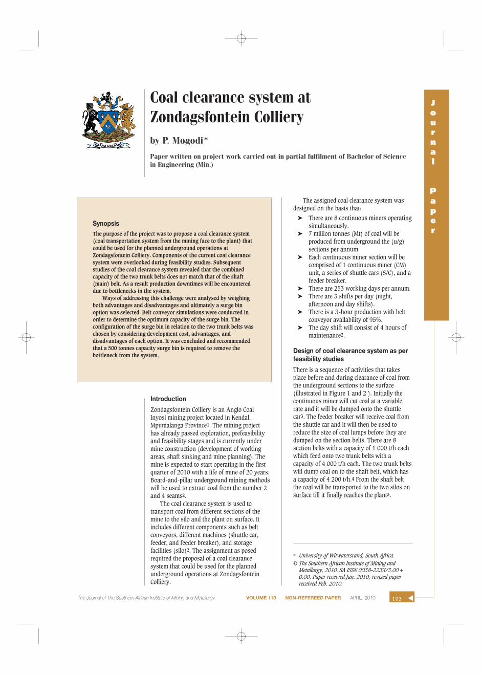
Challenges that will be encountered
Certain components of the current coal clearance system wereoverlooked during feasibility studies. As a result, a numberof challenges will be encountered when the mine isoperational (Figure 3)2. Shaft belt capacity (4 200 t/h) is lessthan the combined capacities of the two trunk belts (8 000t/h)4. As a result, there will be a build-up on the shaft beltresulting in a flooded belt and finally spillage (particularlywhen all the belts operate at peak capacity). In addition tospillage, other challenges that will be encountered are:
➤ Overloading of the shaft belt➤ Increased wear rate on the belt and idlers➤ Breakdown of the system2.
Spillage can trigger spontaneous burning of coal,methane explosion, and coal dust explosion. They can occurif coal gets stuck between moving parts. These are not onlysafety hazards but also health hazards. Worn belts and other
components would require replacement. The overall impact ofthe potential challenges is loss of production time (due tomaintenance and accidents), high cost (for replacements ofthe belt), and loss of coal resource (due to spontaneouscombustion and explosions). As a result, an insufficientamount of coal would be supplied to the coal market (Eskomand export)2.
Overcoming the potential challengesOption A—speeding up the shaft belt
The speed of the coal clearance system shaft belt can beincreased in order to remove the bottleneck. A higher beltspeed will increase the capacity (tonnes per hour)5. Since thecapacity will be higher, belt flooding or buildup of coal willnot take place. Spillage of coal will be minimized.Consequently, more coal (tonnage per hour) will betransported from the sections5.
The downside (disadvantages) of increasing the speed ofthe shaft belt involves the following:
➤ There will be increased wear of the shaft belt.➤ Higher power requirement of the shaft belt section
(power packs will be increased or changed toaccommodate the new speed of the belt).
▲
194 APRIL 2010 VOLUME 110 NON-REFEREED PAPER The Journal of The Southern African Institute of Mining and Metallurgy
Figure 1—Coal clearance system and rates of different components3
Figure 2—Layout of the coal clearance system as per feasibility studies3
➤ When the belt speed is increased, coal tends to lift offthe belt and generate dust.
➤ Spontaneous combustion and coal dust explosion canoccur as a result of the increased amount of coal dustin the ambient atmosphere.
➤ Installation of power-packs and replacement of the beltwill increase the operational cost5.
Option B—reducing tonnage per hour
Reducing tonnage per hour can be achieved by limiting theamount of coal handled by different components of thesystem (i.e. belts and feeder breaker)5. The capacity of thefeeder breaker can be limited to a certain amount (tonnes perhour) in order to get the desired amount of coal on the shaftbelt. Advantages of reducing tonnage per hour are:
➤ Spillage on the shaft belt will be minimized.➤ Since the quantity of coal is controlled on the shaft belt,
belt flooding will not take place.
➤ Mining and engineering downtimes will be minimized.As a result greater operational efficiency will beachieved5.
The downsides of reducing the tonnage per hour in orderto achieve the desired amount of coal on the shaft belt are:
➤ Optimization of the system will be a problem (due tolimited capacity)
➤ The production target of 7 million tonnes per annumwill not be reached5.
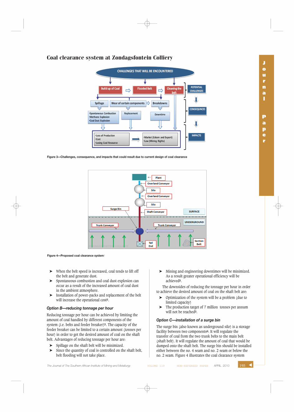
Option C—installation of a surge bin
The surge bin (also known as underground silo) is a storagefacility between two components6. It will regulate thetransfer of coal from the two trunk belts to the main belt(shaft belt). It will regulate the amount of coal that would bedumped onto the shaft belt. The surge bin should be installedeither between the no. 4 seam and no. 2 seam or below theno. 2 seam. Figure 4 illustrates the coal clearance system
Coal clearance system at Zondagsfontein CollieryJournal
Paper
195The Journal of The Southern African Institute of Mining and Metallurgy VOLUME 110 NON-REFEREED PAPER APRIL 2010 ▲
Figure 3—Challenges, consequence, and impacts that could result due to current design of coal clearance
Figure 4—Proposed coal clearance system3

Coal clearance system at Zondagsfontein Colliery
with the surge bin installed between two trunk belts and theshaft belt. Coal from the trunk belt will be stored temporarilybefore being transferred to the main shaft belt6.
Advantages of a surge bin (bunker) in a coal clearancesystem are:
➤ The surge bin facilitates belt overruns on shutdownwithout spillage.
➤ It minimizes spillage at transfer points between the twotrunk belts and the main shaft belt.
➤ An underground bunker will facilitate a single point oftransfer onto the shaft belt.
➤ It ensures controlled and constant feed onto the shaftbelt6.
Disadvantages of a surge bin in a coal clearance systemare:
➤ The initial cost of the surge bin is high.➤ It is a fixed design (for the life of mine, hence it cannot
be relocated).➤ During surge bin breakdowns, production will be
stopped6.
Futher analysis of option C
Based on the analysis that was conducted, option C wasselected because it will have a relatively positive effect onproduction and safety of the mine. A conveyor simulationwas conducted in order to determine the capacity of the surgebin. Other parameters that were analysed are underground
silo capacity, silo outlet, total production, total spillage, andmaximum and average level of the silo6. Table I shows theresults of eight scenarios that were analysed.
The capacity of the surge bin was limited to 500 tonnesdue to the high initial cost of development, hence anycapacity above that was not considered6. From Table I it canbe deduced that scenarios 3, 5 and 8 have minimum spillagecompared with the other scenarios. Hence scenario 5 was themost suitable with a belt capacity of 4 200 tonnes/hour andno spillage at the underground silo. It gives the sameadvantages as scenario 8 but at a lower capacity, and hencelower capital cost. Figure 5 illustrates the tonnage profile ofcoal in the surge bin for scenario 5 over a period of 170hours. The maximum capacity of the surge bin will not bereached, so spillage will not be encountered.
Layout and location of the surge bin
There are two layouts that can be used to connect the currentcoal clearance system with the surge bin2. The layout of thesurge bin dictates where it should be located. In option 1 thesurge bin is installed between no. 4 seam and no. 2 seam,whereas for option 2 the surge bin should be below no. 2seam. Figure 6 shows the designs of the layout and locationof the surge bin for both options 1 and 2. The mainadvantages of using option1 is that the surge bin can be usedto store coal from the two seams. The main disadavantage isaccelerated wear of the shaft belt. Option 2 involves instal-
▲
196
Figure 5—Scenario 5 of the surge bin level✖
Table I
Further analysis of option 1✖
Scenario Surge bin Outlet rate of surge Total production Total spillage Max level Average level Max level ofcapacity bin (tons/hour) (@ surge bin) of surge bin of surge bin surface silo
1 350 4200 297431 277 350 40.9 58892 400 4200 297747 95 400 41.63 58963 450 4200 297309 15 450 33.1 59474 450 4000 297089 397 450 58.25 59545 500 4200 297279 0 465 34.1 59566 500 4000 297258 350 500 60.8 59717 600 4000 297280 225 600 54 59838 600 4200 297279 0 465 34 5956
20 40 60 80 100 120 140 160
Hours
Scenario 5 (surge bin level)500
450
400
350
300
250
200
150
100
50
0
To
ns
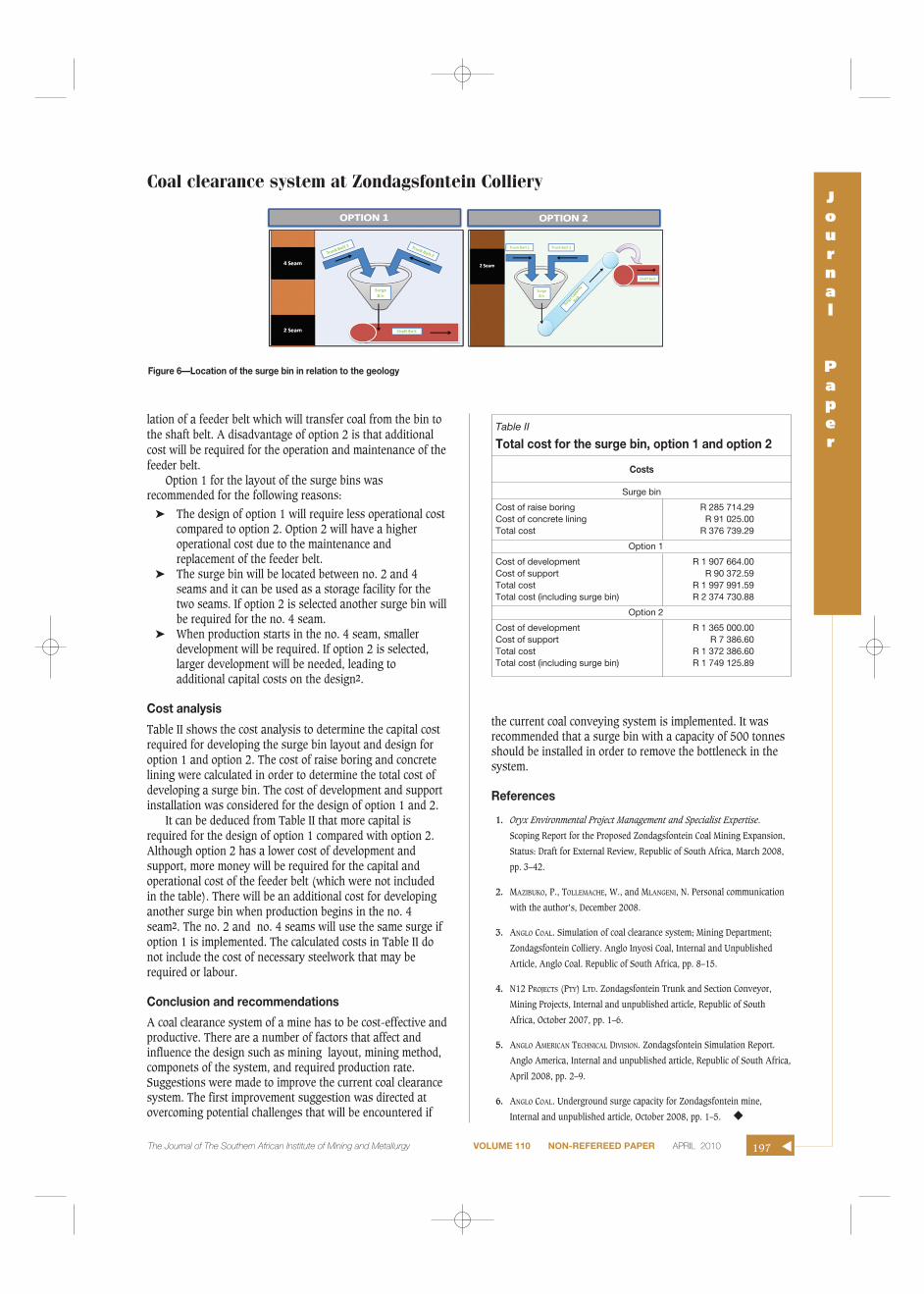
lation of a feeder belt which will transfer coal from the bin tothe shaft belt. A disadvantage of option 2 is that additionalcost will be required for the operation and maintenance of thefeeder belt.
Option 1 for the layout of the surge bins wasrecommended for the following reasons:
➤ The design of option 1 will require less operational costcompared to option 2. Option 2 will have a higheroperational cost due to the maintenance andreplacement of the feeder belt.
➤ The surge bin will be located between no. 2 and 4seams and it can be used as a storage facility for thetwo seams. If option 2 is selected another surge bin willbe required for the no. 4 seam.
➤ When production starts in the no. 4 seam, smallerdevelopment will be required. If option 2 is selected,larger development will be needed, leading toadditional capital costs on the design2.
Cost analysis
Table II shows the cost analysis to determine the capital costrequired for developing the surge bin layout and design foroption 1 and option 2. The cost of raise boring and concretelining were calculated in order to determine the total cost ofdeveloping a surge bin. The cost of development and supportinstallation was considered for the design of option 1 and 2.
It can be deduced from Table II that more capital isrequired for the design of option 1 compared with option 2.Although option 2 has a lower cost of development andsupport, more money will be required for the capital andoperational cost of the feeder belt (which were not includedin the table). There will be an additional cost for developinganother surge bin when production begins in the no. 4seam2. The no. 2 and no. 4 seams will use the same surge ifoption 1 is implemented. The calculated costs in Table II donot include the cost of necessary steelwork that may berequired or labour.
Conclusion and recommendations
A coal clearance system of a mine has to be cost-effective andproductive. There are a number of factors that affect andinfluence the design such as mining layout, mining method,componets of the system, and required production rate.Suggestions were made to improve the current coal clearancesystem. The first improvement suggestion was directed atovercoming potential challenges that will be encountered if
the current coal conveying system is implemented. It wasrecommended that a surge bin with a capacity of 500 tonnesshould be installed in order to remove the bottleneck in thesystem.
References
1. Oryx Environmental Project Management and Specialist Expertise.
Scoping Report for the Proposed Zondagsfontein Coal Mining Expansion,
Status: Draft for External Review, Republic of South Africa, March 2008,
pp. 3–42.
2. MAZIBUKO, P., TOLLEMACHE, W., and MLANGENI, N. Personal communication
with the author’s, December 2008.
3. ANGLO COAL. Simulation of coal clearance system; Mining Department;
Zondagsfontein Colliery. Anglo Inyosi Coal, Internal and Unpublished
Article, Anglo Coal. Republic of South Africa, pp. 8–15.
4. N12 PROJECTS (PTY) LTD. Zondagsfontein Trunk and Section Conveyor,
Mining Projects, Internal and unpublished article, Republic of South
Africa, October 2007, pp. 1–6.
5. ANGLO AMERICAN TECHNICAL DIVISION. Zondagsfontein Simulation Report.
Anglo America, Internal and unpublished article, Republic of South Africa,
April 2008, pp. 2–9.
6. ANGLO COAL. Underground surge capacity for Zondagsfontein mine,
Internal and unpublished article, October 2008, pp. 1–5. ◆
Coal clearance system at Zondagsfontein CollieryJournal
Paper
The Journal of The Southern African Institute of Mining and Metallurgy VOLUME 110 NON-REFEREED PAPER APRIL 2010 197 ▲
Table II
Total cost for the surge bin, option 1 and option 2
Costs
Surge bin
Cost of raise boring R 285 714.29Cost of concrete lining R 91 025.00Total cost R 376 739.29
Option 1
Cost of development R 1 907 664.00Cost of support R 90 372.59Total cost R 1 997 991.59Total cost (including surge bin) R 2 374 730.88
Option 2
Cost of development R 1 365 000.00Cost of support R 7 386.60Total cost R 1 372 386.60Total cost (including surge bin) R 1 749 125.89
Figure 6—Location of the surge bin in relation to the geology