Embed Size (px)
Citation preview
R Adams
CO2 Capture and Pumping Tutorial
Ron Adams, Global Portfolio Manager – Petroleum
Sulzer Pumps Houston, TX
Member API 610/ISO 13709, API 676, API 685 and Intl Pump Users Symposium Advisory Committee
eral carbona ton
R Adams
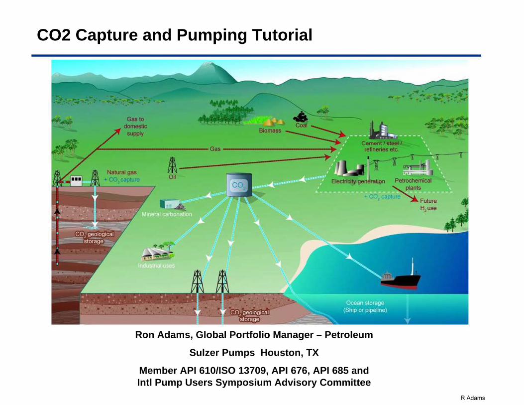
Contents
• CO2 Value Chain and Scrubbing Methods
• Is it a Pump or Compressor application ??
• Super Critical CO2 Applications– Experiences, Thermodynamics, Rotor Construction,
Mechanical Seals
• Recent CO2 application pictures
• Final Exam
R Adams
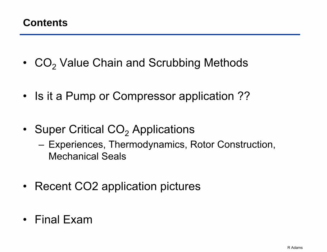
CO2 Emissions: Sources
World CO2 emissions by sector 1971 - 2001
Fossil fuels = dominant form of energy utilized in the world (86%)and account for 75% of current anthropogenic CO2 emissionsCO2 emissions have probably doubled in last 40 years
Total emissions from fossil fuel consumption 24,000 MtCO2 per year (in 2001)
Large stationary sources (> 0.1 Mt CO2 per year)
13,466 MtCO2yr-1Total
91 MtCO2yr-1Bioethanol and bioenergy
Biomass33 MtCO2yr-1Other sources 50 MtCO2yr-1Oil and gas processing
379 MtCO2yr-1Petrochemical industry 646 MtCO2yr-1Iron and steel industry 798 MtCO2yr-1Refineries 932 MtCO2yr-1Cement production
10,539 MtCO2yr-1Power Fossil fuels
Source: IPCC, 2005
anthropogenic = derived from human activities
R Adams
Getting Green is Expensive…
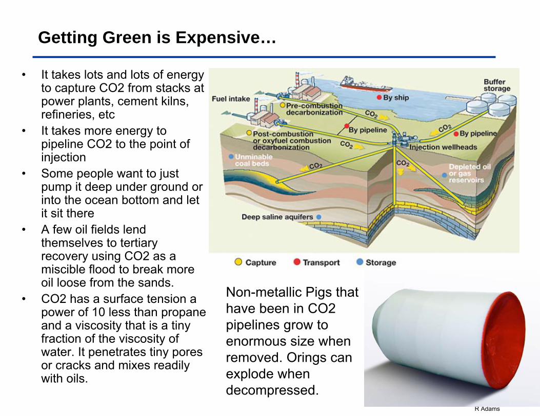
• It takes lots and lots of energy to capture CO2 from stacks at power plants, cement kilns, refineries, etc
• It takes more energy to pipeline CO2 to the point of injection
• Some people want to just pump it deep under ground or into the ocean bottom and let it sit there
• A few oil fields lend themselves to tertiary recovery using CO2 as a miscible flood to break more oil loose from the sands.
• CO2 has a surface tension a power of 10 less than propane and a viscosity that is a tiny fraction of the viscosity of water. It penetrates tiny pores or cracks and mixes readily with oils.
Non-metallic Pigs that have been in CO2 pipelines grow to enormous size when removed. Orings can explode when decompressed.
R Adams
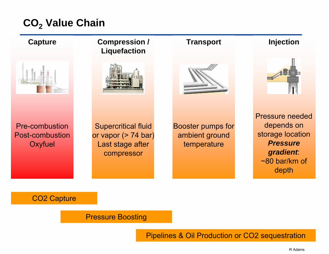
CO2 Value Chain
Capture
Pre-combustionPost-combustion
Oxyfuel
Compression /Liquefaction
Supercritical fluid or vapor (> 74 bar)
Last stage after compressor
Transport
Booster pumps for ambient ground
temperature
Injection
Pressure needed depends on
storage locationPressure gradient:
~80 bar/km of depth
CO2 Capture
Pressure Boosting
Pipelines & Oil Production or CO2 sequestration
R Adams
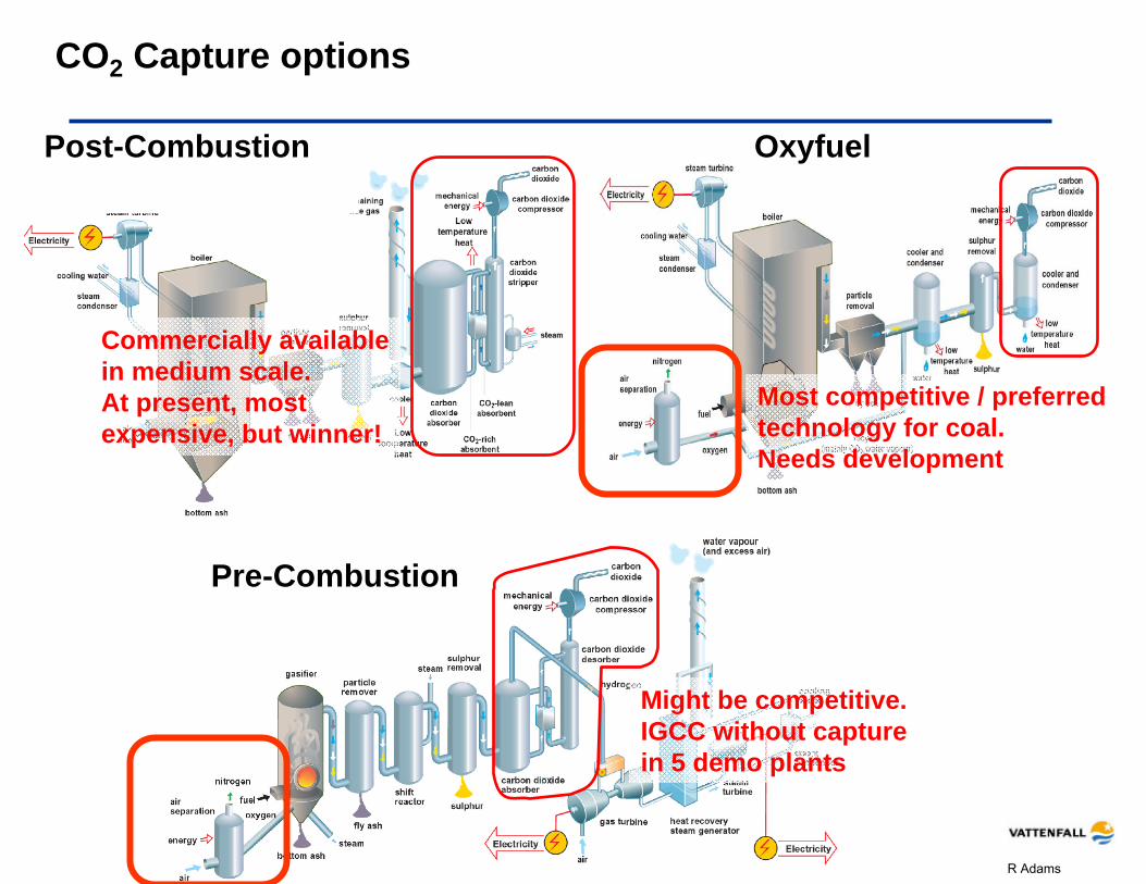
CO2 Capture options
Might be competitive.IGCC without capture in 5 demo plants
Commercially available in medium scale.At present, most expensive, but winner!
Most competitive / preferred technology for coal.Needs development
Post-Combustion Oxyfuel
Pre-Combustion
R Adams
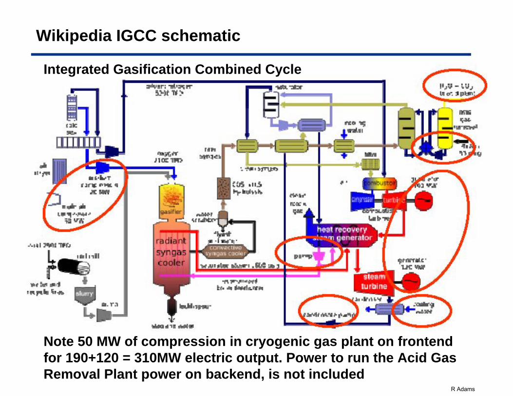
Wikipedia IGCC schematic
Note 50 MW of compression in cryogenic gas plant on frontend for 190+120 = 310MW electric output. Power to run the Acid Gas Removal Plant power on backend, is not included
Integrated Gasification Combined Cycle
...... ,......, 'Tff.l
R Adams
Cost of Plant and kWh estimates for CO2 scrubbing
• Following 2 slides from this presentation
R Adams
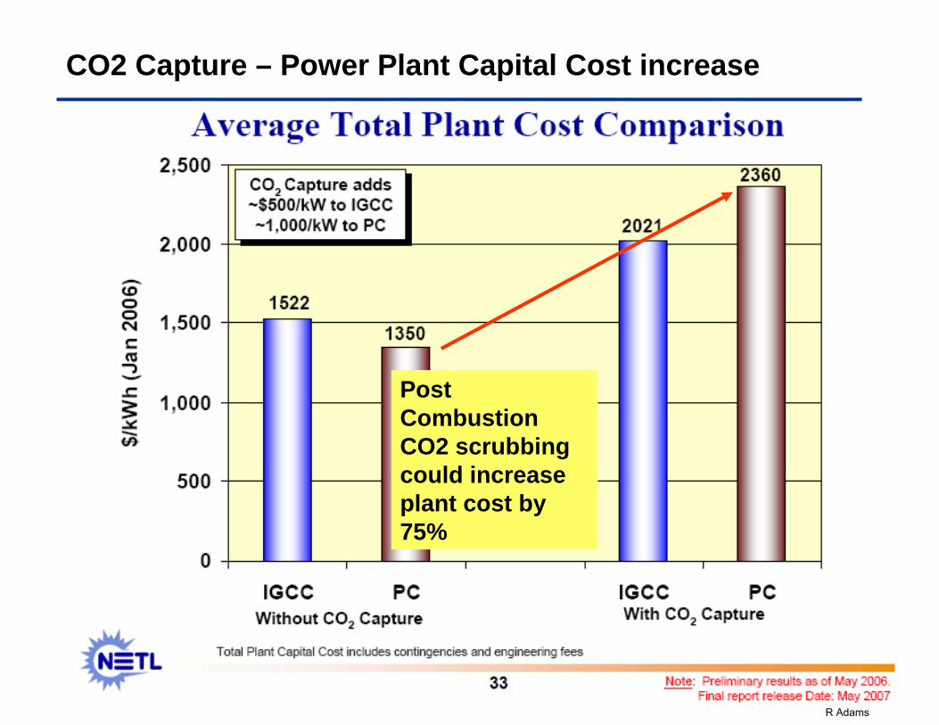
CO2 Capture – Power Plant Capital Cost increase
Post Combustion CO2 scrubbing could increase plant cost by 75%
R Adams
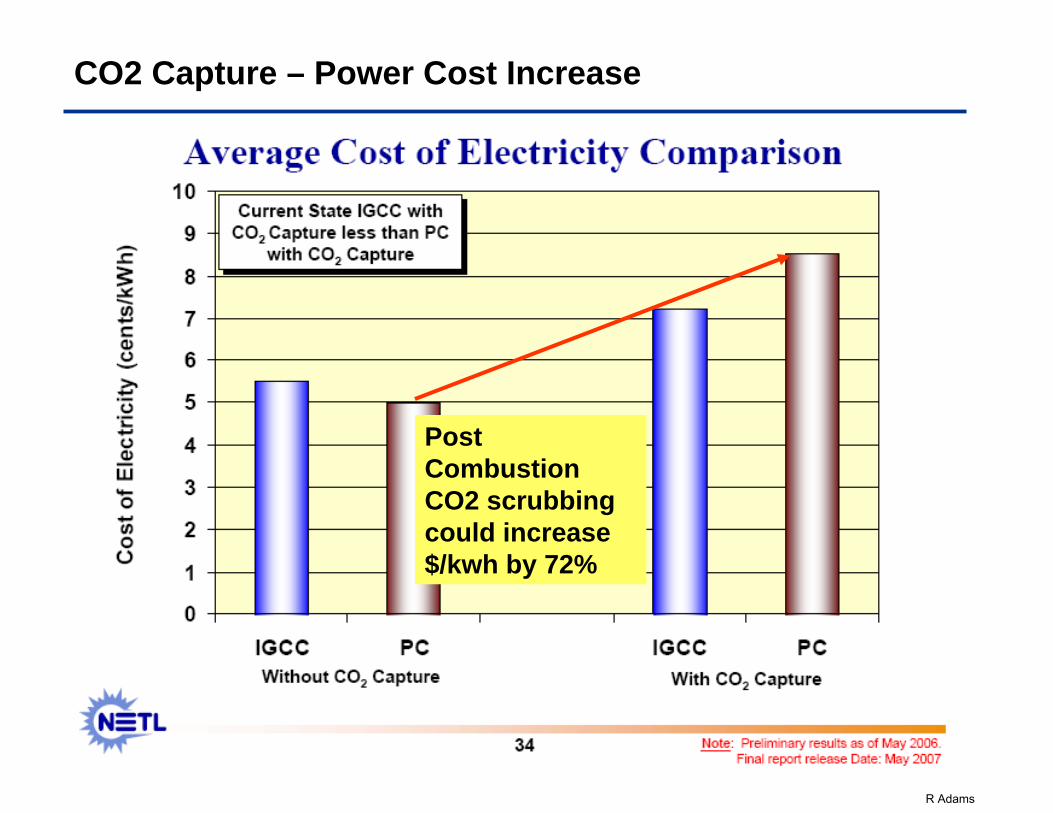
CO2 Capture – Power Cost Increase
Post Combustion CO2 scrubbing could increase $/kwh by 72%
R Adams
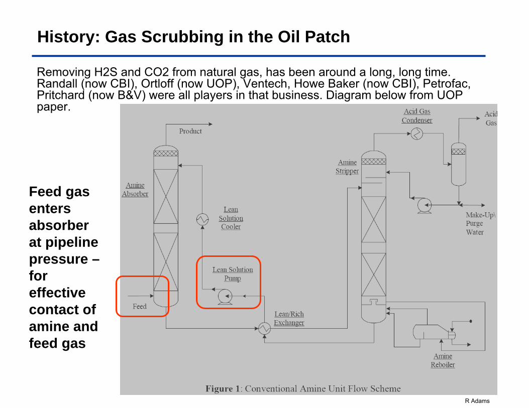
History: Gas Scrubbing in the Oil Patch
Removing H2S and CO2 from natural gas, has been around a long, long time. Randall (now CBI), Ortloff (now UOP), Ventech, Howe Baker (now CBI), Petrofac, Pritchard (now B&V) were all players in that business. Diagram below from UOP paper.
Feed gas enters absorber at pipeline pressure –for effective contact of amine and feed gas
R Adams
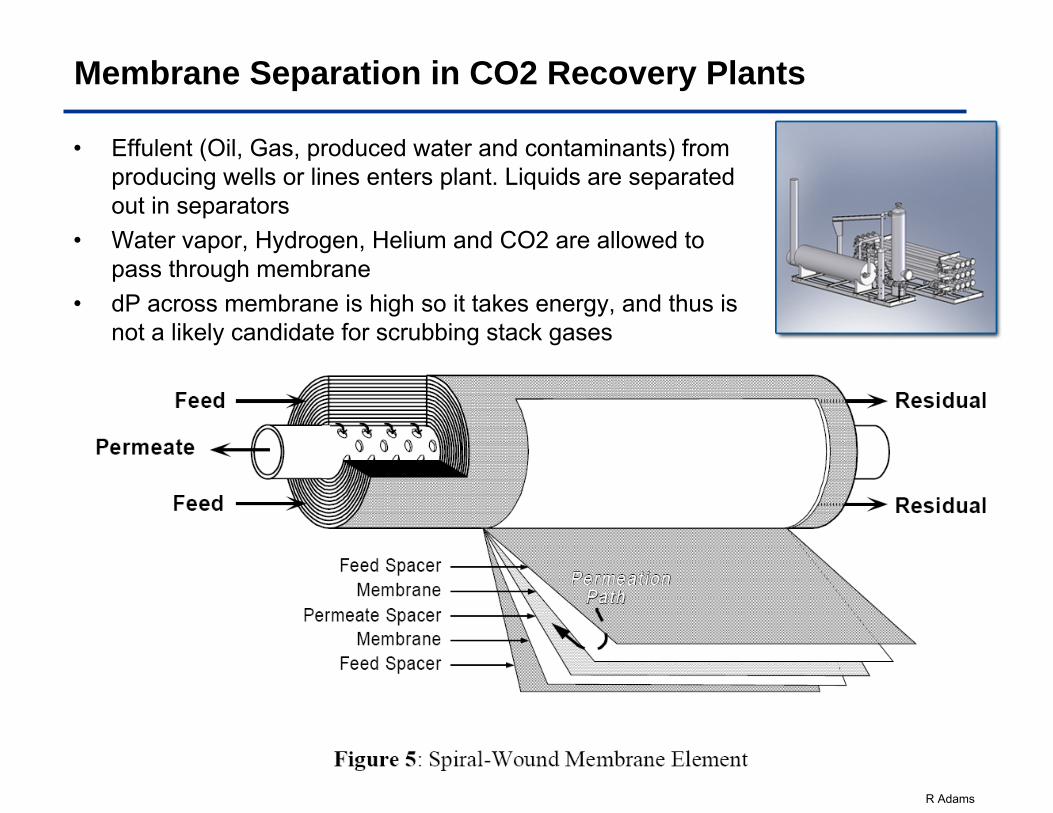
Membrane Separation in CO2 Recovery Plants
• Effulent (Oil, Gas, produced water and contaminants) from producing wells or lines enters plant. Liquids are separated out in separators
• Water vapor, Hydrogen, Helium and CO2 are allowed to pass through membrane
• dP across membrane is high so it takes energy, and thus is not a likely candidate for scrubbing stack gases
www.newpointgas.com
R Adams
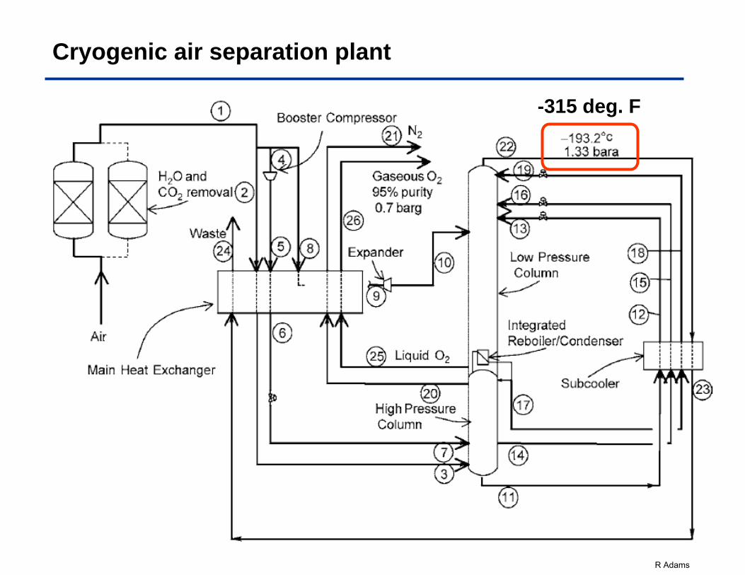
Cryogenic air separation plant
-315 deg. F
R Adams
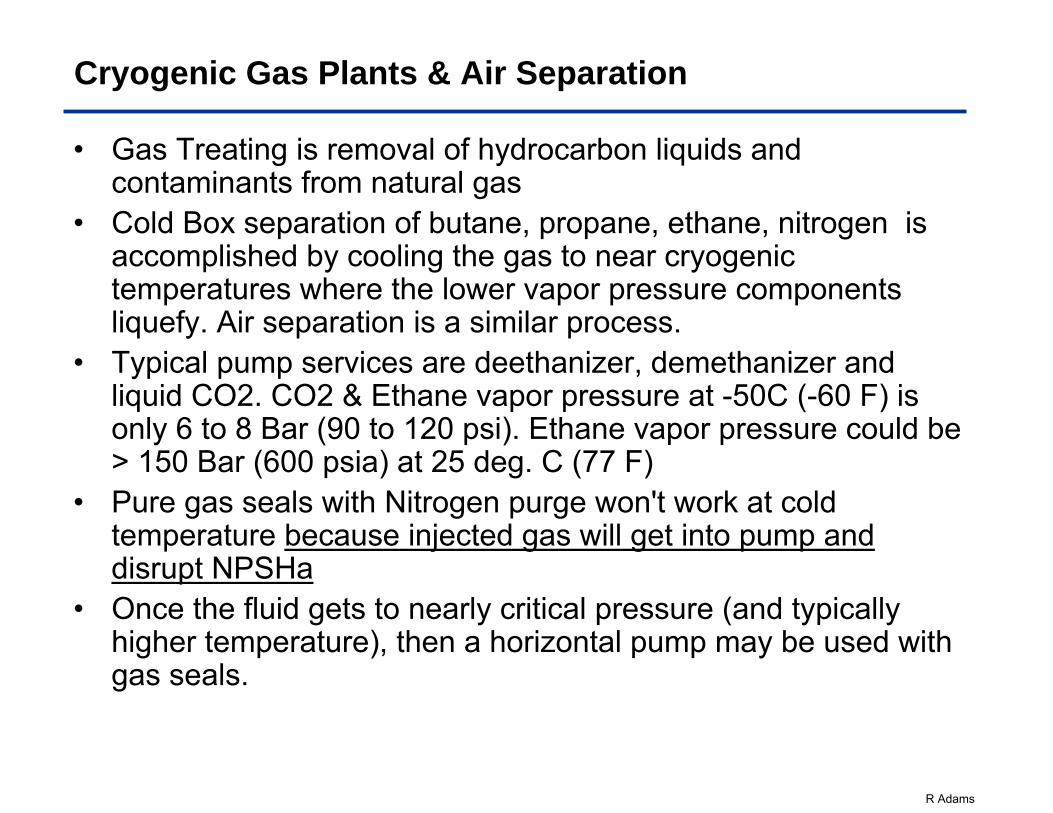
Cryogenic Gas Plants & Air Separation
• Gas Treating is removal of hydrocarbon liquids and contaminants from natural gas
• Cold Box separation of butane, propane, ethane, nitrogen is accomplished by cooling the gas to near cryogenic temperatures where the lower vapor pressure components liquefy. Air separation is a similar process.
• Typical pump services are deethanizer, demethanizer and liquid CO2. CO2 & Ethane vapor pressure at -50C (-60 F) is only 6 to 8 Bar (90 to 120 psi). Ethane vapor pressure could be > 150 Bar (600 psia) at 25 deg. C (77 F)
• Pure gas seals with Nitrogen purge won't work at cold temperature because injected gas will get into pump and disrupt NPSHa
• Once the fluid gets to nearly critical pressure (and typically higher temperature), then a horizontal pump may be used with gas seals.
R Adams
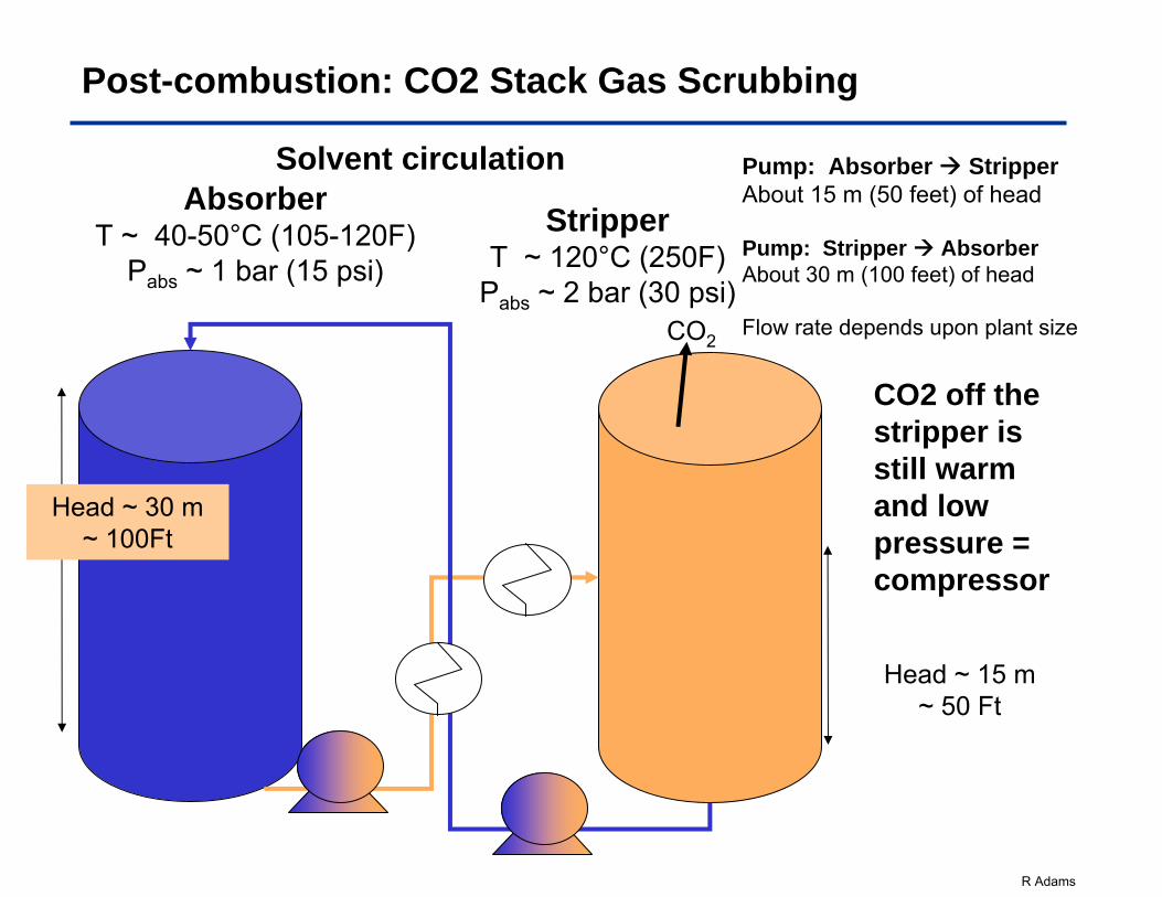
Post-combustion: CO2 Stack Gas Scrubbing
Solvent circulationAbsorber
T ~ 40-50°C (105-120F)Pabs ~ 1 bar (15 psi)
Head ~ 15 m~ 50 Ft
StripperT ~ 120°C (250F)
Pabs ~ 2 bar (30 psi)
Head ~ 30 m ~ 100Ft
Pump: Absorber StripperAbout 15 m (50 feet) of head
Pump: Stripper AbsorberAbout 30 m (100 feet) of head
Flow rate depends upon plant sizeCO2
CO2 off the stripper is still warm and low pressure = compressor
R Adams
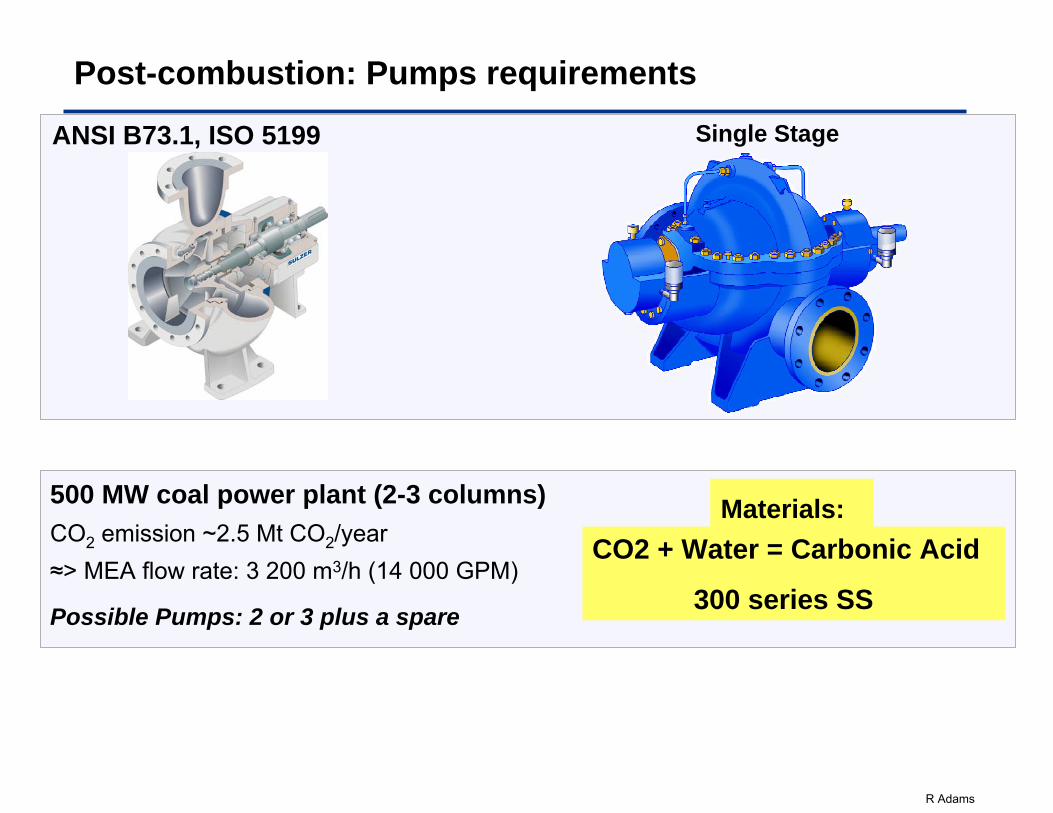
Post-combustion: Pumps requirements
ANSI B73.1, ISO 5199
500 MW coal power plant (2-3 columns)CO2 emission ~2.5 Mt CO2/year ≈> MEA flow rate: 3 200 m3/h (14 000 GPM)
Possible Pumps: 2 or 3 plus a spare
Single Stage
Materials:CO2 + Water = Carbonic Acid
300 series SS
R Adams
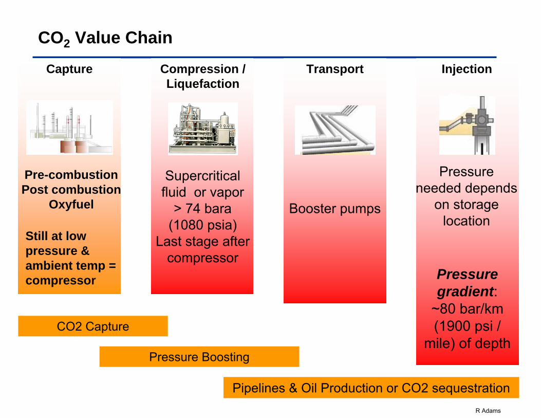
CO2 Value Chain
Capture
Pre-combustionPost combustion
Oxyfuel
Compression /Liquefaction
Supercritical fluid or vapor
> 74 bara (1080 psia)
Last stage after compressor
Transport
Booster pumps
CO2 Capture
Pressure Boosting
Pipelines & Oil Production or CO2 sequestration
Injection
Pressure needed depends
on storage location
Still at low pressure & ambient temp = compressor Pressure
gradient: ~80 bar/km (1900 psi /
mile) of depth
R Adams
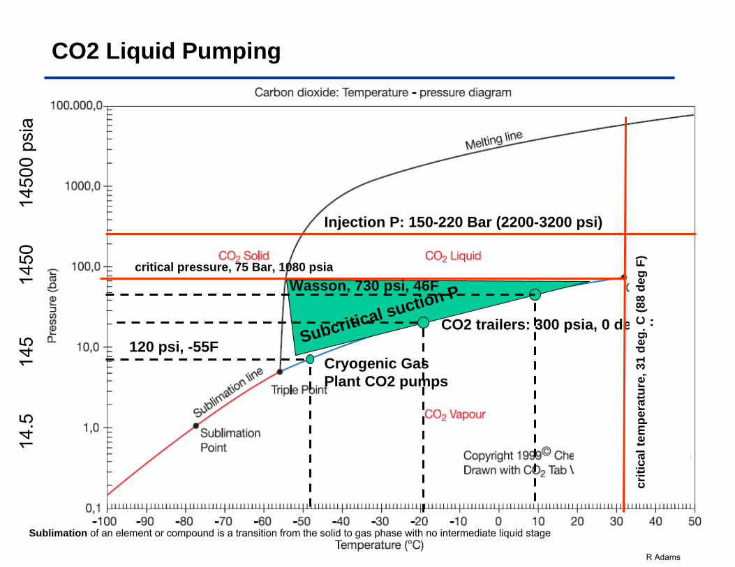
CO2 Liquid Pumping
Subcritical suction P
CO2 trailers: 300 psia, 0 deg F
Sublimation of an element or compound is a transition from the solid to gas phase with no intermediate liquid stage
Wasson, 730 psi, 46F
14.5
14
5
1450
145
00 p
sia
Cryogenic Gas Plant CO2 pumps
120 psi, -55F
Injection P: 150-220 Bar (2200-3200 psi)
critical pressure, 75 Bar, 1080 psia
criti
cal t
empe
ratu
re, 3
1 de
g. C
(88
deg
F)
R Adams
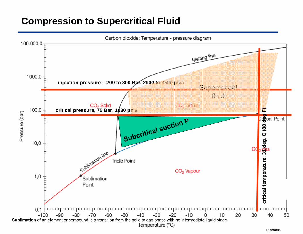
Compression to Supercritical Fluid
critical pressure, 75 Bar, 1080 psia
injection pressure – 200 to 300 Bar, 2900 to 4500 psiaSupercritical
fluid
Sublimation of an element or compound is a transition from the solid to gas phase with no intermediate liquid stage
criti
cal t
empe
ratu
re, 3
1 de
g. C
(88
deg
F)
Subcritical suction P
R Adams
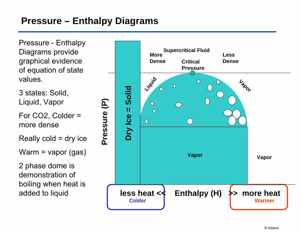
Pressure – Enthalpy Diagrams
Pressure - Enthalpy Diagrams provide graphical evidence of equation of state values.
3 states: Solid, Liquid, Vapor
For CO2, Colder = more dense
Really cold = dry ice
Warm = vapor (gas)
2 phase dome is demonstration of boiling when heat is added to liquid
Few Bubbles
Many Bubbles
less heat << Enthalpy (H) >> more heat
Pres
sure
(P)
Liqu
id Vapor2 Phase Dome
Vapor
Colder Warmer
Supercritical FluidMore Dense
Less DenseCritical
Pressure
Dry
Ice
= So
lid
Vapor
R Adams
Critical Pressure
Dry
Ice
= So
lid
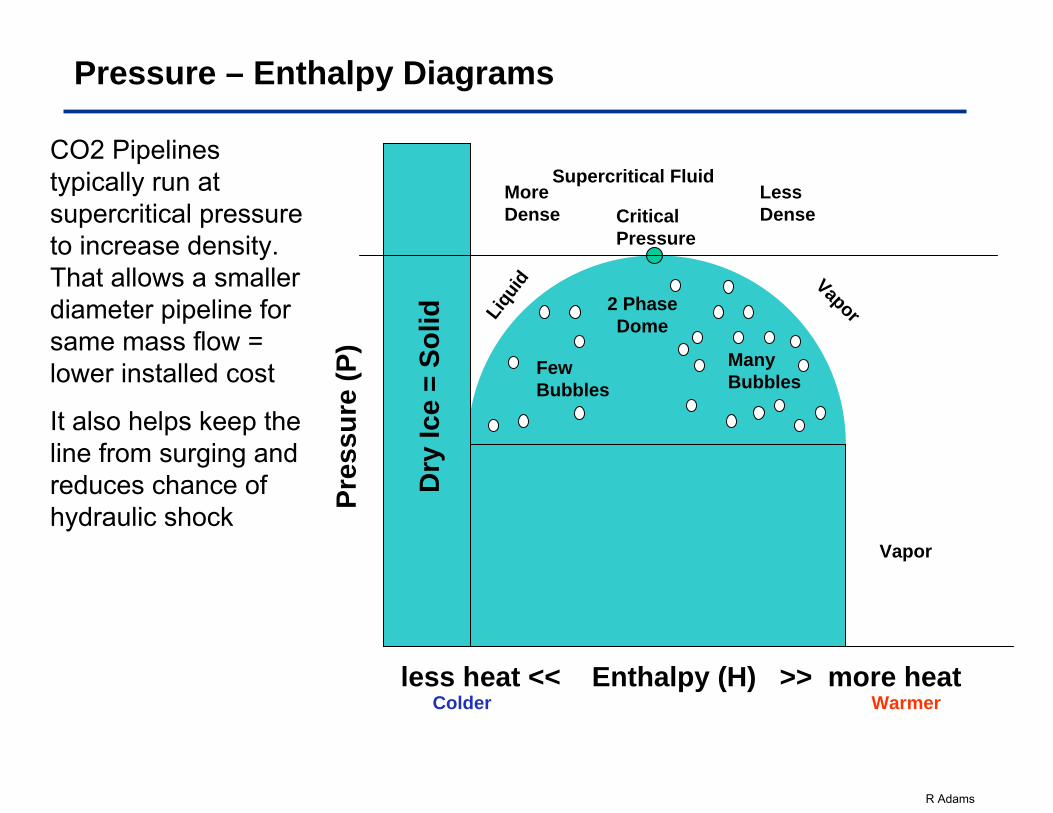
Pressure – Enthalpy Diagrams
CO2 Pipelines typically run at supercritical pressure to increase density. That allows a smaller diameter pipeline for same mass flow = lower installed cost
It also helps keep the line from surging and reduces chance of hydraulic shock
Few Bubbles
Many Bubbles
less heat << Enthalpy (H) >> more heat
Pres
sure
(P)
Liqu
id Vapor2 Phase Dome
Vapor
Colder Warmer
Supercritical FluidMore Dense
Less Dense
R Adams
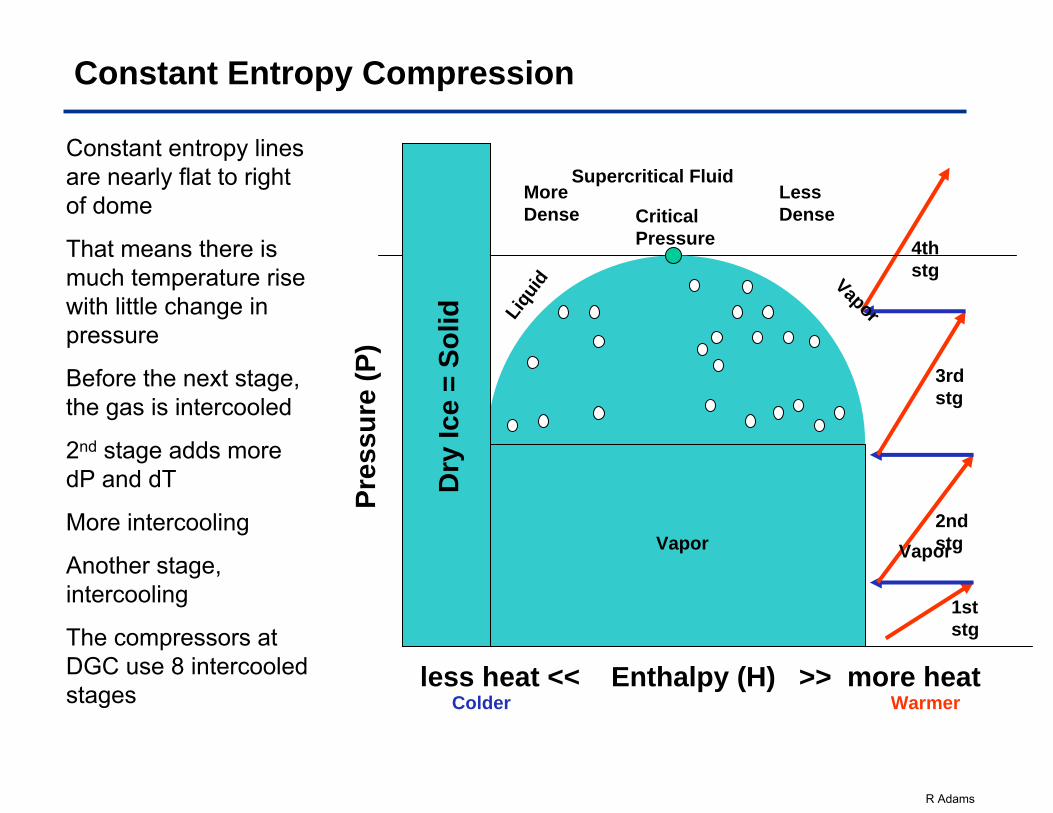
Constant Entropy Compression
Constant entropy lines are nearly flat to right of dome
That means there is much temperature rise with little change in pressure
Before the next stage, the gas is intercooled
2nd stage adds more dP and dT
More intercooling
Another stage, intercooling
The compressors at DGC use 8 intercooled stages
1st stg
2nd stg
3rd stg
4th stg
Few Bubbles
Many Bubbles
less heat << Enthalpy (H) >> more heat
Pres
sure
(P)
Liqu
id Vapor2 Phase Dome
Vapor
Colder Warmer
Supercritical FluidMore Dense
Less DenseCritical
Pressure
Dry
Ice
= So
lid
Vapor
R Adams
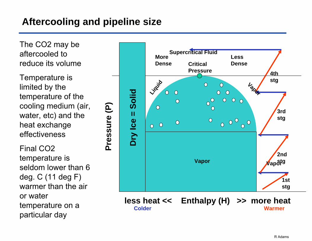
Aftercooling and pipeline size
The CO2 may be aftercooled to reduce its volume
Temperature is limited by the temperature of the cooling medium (air, water, etc) and the heat exchange effectiveness
Final CO2 temperature is seldom lower than 6 deg. C (11 deg F) warmer than the air or water temperature on a particular day
1st stg
2nd stg
3rd stg
4th stg
Few Bubbles
Many Bubbles
less heat << Enthalpy (H) >> more heat
Pres
sure
(P)
Liqu
id Vapor2 Phase Dome
Vapor
Colder Warmer
Supercritical FluidMore Dense
Less DenseCritical
Pressure
Dry
Ice
= So
lid
Vapor
R Adams
Supercritical CO2 Pump Applications
• Super Critical CO2 Applications– Experiences, – Thermodynamics, – Rotor Construction, – Mechanical Seals
R Adams
Super Critical CO2 Applications
Once we have scrubbed the CO2 out of the stack gas or other source, we then compress it, or pump it, to pipeline pressures –typically between 100 and 150 Bar (1440 and 1900 psi)
CO2 has very little viscosity and thus is non-lubricatingWarm CO2 is compressible – more m3/h (GPM) will go into the
pump than will come out. Mass flow rate stays the sameWhen we compress CO2, it get warmer if we start at ambient
temperaturesThat leads us to focus on our • Experience with CO2• Understanding of performance on CO2 (Thermodynamics)• Experience with non-lubricating hydrocarbons• Rotor construction• Bearing systems• Mechanical seals
R Adams
CO2 – Early Days in West Texas
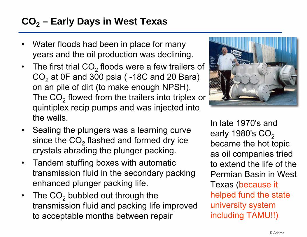
• Water floods had been in place for many years and the oil production was declining.
• The first trial CO2 floods were a few trailers of CO2 at 0F and 300 psia ( -18C and 20 Bara) on an pile of dirt (to make enough NPSH). The CO2 flowed from the trailers into triplex or quintiplex recip pumps and was injected into the wells.
• Sealing the plungers was a learning curve since the CO2 flashed and formed dry ice crystals abrading the plunger packing.
• Tandem stuffing boxes with automatic transmission fluid in the secondary packing enhanced plunger packing life.
• The CO2 bubbled out through the transmission fluid and packing life improved to acceptable months between repair
In late 1970's and early 1980's CO2became the hot topic as oil companies tried to extend the life of the Permian Basin in West Texas (because it helped fund the state university system including TAMU!!)
R Adams
CO2 for well fracturing – 1980's
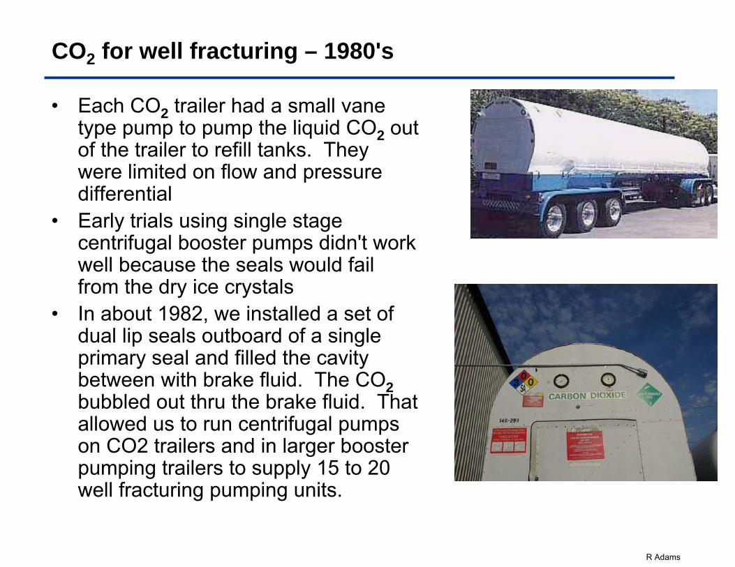
• Each CO2 trailer had a small vane type pump to pump the liquid CO2 out of the trailer to refill tanks. They were limited on flow and pressure differential
• Early trials using single stage centrifugal booster pumps didn't work well because the seals would fail from the dry ice crystals
• In about 1982, we installed a set of dual lip seals outboard of a single primary seal and filled the cavity between with brake fluid. The CO2bubbled out thru the brake fluid. That allowed us to run centrifugal pumps on CO2 trailers and in larger booster pumping trailers to supply 15 to 20 well fracturing pumping units.
R Adams
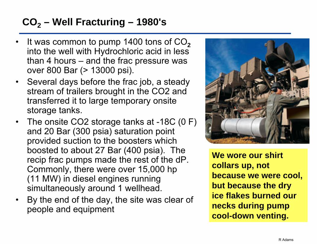
CO2 – Well Fracturing – 1980's
• It was common to pump 1400 tons of CO2into the well with Hydrochloric acid in less than 4 hours – and the frac pressure was over 800 Bar (> 13000 psi).
• Several days before the frac job, a steady stream of trailers brought in the CO2 and transferred it to large temporary onsite storage tanks.
• The onsite CO2 storage tanks at -18C (0 F) and 20 Bar (300 psia) saturation point provided suction to the boosters which boosted to about 27 Bar (400 psia). The recip frac pumps made the rest of the dP. Commonly, there were over 15,000 hp (11 MW) in diesel engines running simultaneously around 1 wellhead.
• By the end of the day, the site was clear of people and equipment
We wore our shirt collars up, not because we were cool, but because the dry ice flakes burned our necks during pump cool-down venting.
R Adams
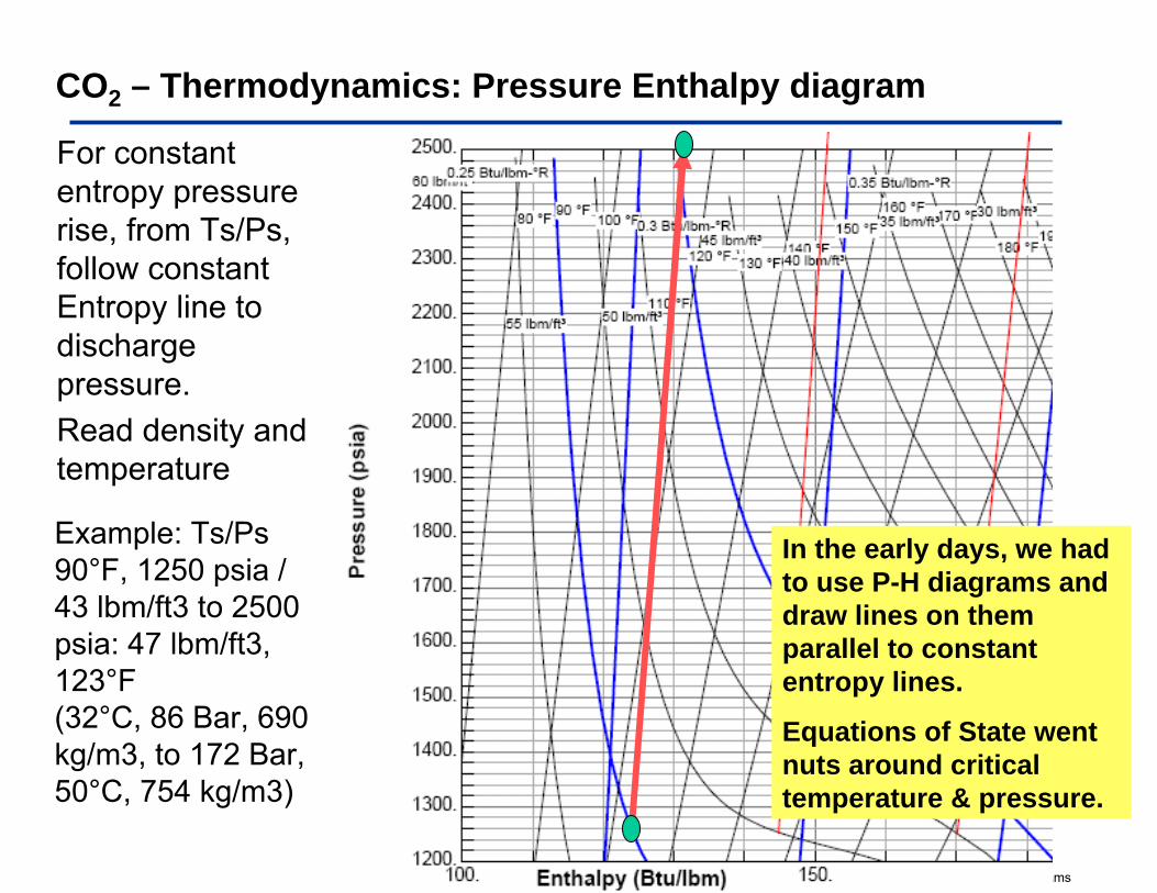
CO2 – Thermodynamics: Pressure Enthalpy diagram
For constant entropy pressure rise, from Ts/Ps, follow constant Entropy line to discharge pressure. Read density and temperature
Example: Ts/Ps90°F, 1250 psia / 43 lbm/ft3 to 2500 psia: 47 lbm/ft3, 123°F (32°C, 86 Bar, 690 kg/m3, to 172 Bar, 50°C, 754 kg/m3)
In the early days, we had to use P-H diagrams and draw lines on them parallel to constant entropy lines.
Equations of State went nuts around critical temperature & pressure.
R Adams
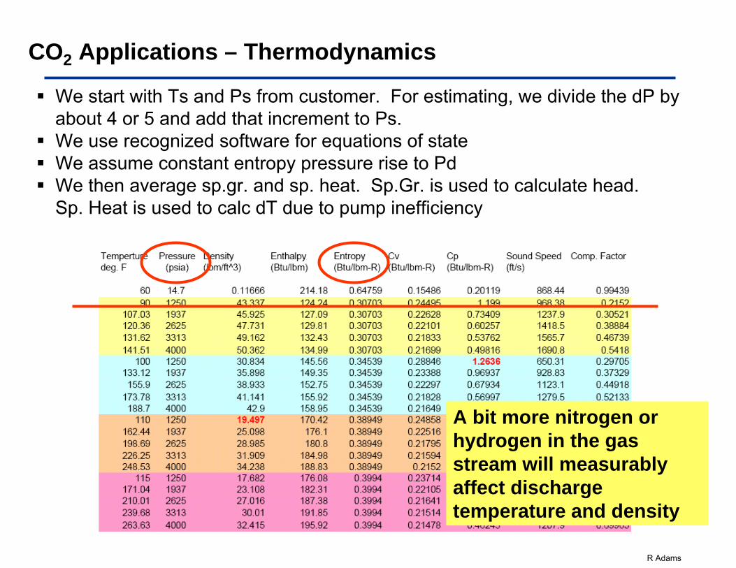
We start with Ts and Ps from customer. For estimating, we divide the dP by about 4 or 5 and add that increment to Ps.We use recognized software for equations of stateWe assume constant entropy pressure rise to PdWe then average sp.gr. and sp. heat. Sp.Gr. is used to calculate head. Sp. Heat is used to calc dT due to pump inefficiency
CO2 Applications – Thermodynamics
A bit more nitrogen or hydrogen in the gas stream will measurably affect discharge temperature and density
R Adams
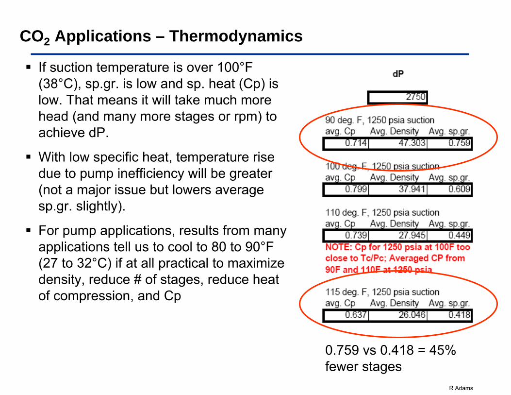
If suction temperature is over 100°F (38°C), sp.gr. is low and sp. heat (Cp) is low. That means it will take much more head (and many more stages or rpm) to achieve dP.
With low specific heat, temperature rise due to pump inefficiency will be greater (not a major issue but lowers average sp.gr. slightly).
For pump applications, results from many applications tell us to cool to 80 to 90°F (27 to 32°C) if at all practical to maximize density, reduce # of stages, reduce heat of compression, and Cp
0.759 vs 0.418 = 45% fewer stages
CO2 Applications – Thermodynamics
R Adams
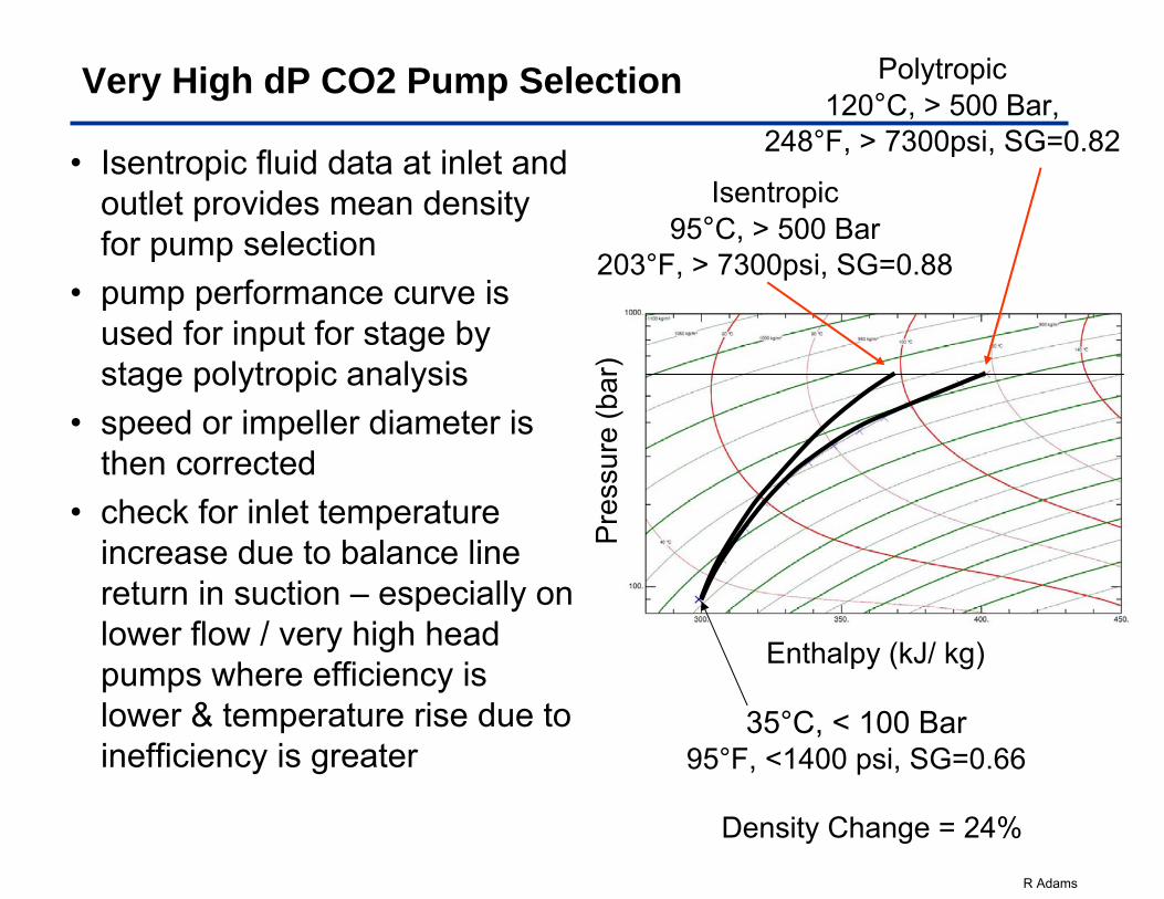
Very High dP CO2 Pump Selection
• Isentropic fluid data at inlet and outlet provides mean density for pump selection
• pump performance curve is used for input for stage by stage polytropic analysis
• speed or impeller diameter is then corrected
• check for inlet temperature increase due to balance line return in suction – especially on lower flow / very high head pumps where efficiency is lower & temperature rise due to inefficiency is greater
Pre
ssur
e(b
ar)
Enthalpy (kJ/ kg)
35°C, < 100 Bar95°F, <1400 psi, SG=0.66
Polytropic 120°C, > 500 Bar,
248°F, > 7300psi, SG=0.82
Isentropic95°C, > 500 Bar
203°F, > 7300psi, SG=0.88
Density Change = 24%
R Adams
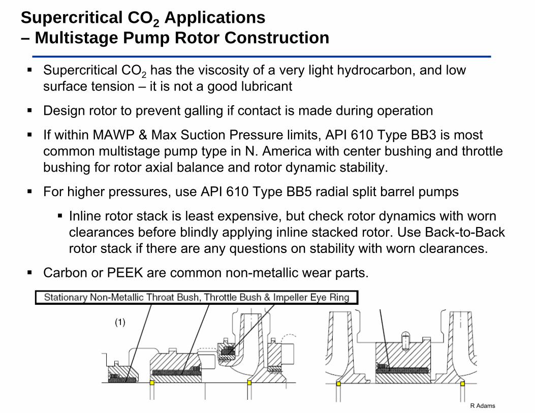
Supercritical CO2 has the viscosity of a very light hydrocarbon, and low surface tension – it is not a good lubricant
Design rotor to prevent galling if contact is made during operation
If within MAWP & Max Suction Pressure limits, API 610 Type BB3 is most common multistage pump type in N. America with center bushing and throttle bushing for rotor axial balance and rotor dynamic stability.
For higher pressures, use API 610 Type BB5 radial split barrel pumps
Inline rotor stack is least expensive, but check rotor dynamics with worn clearances before blindly applying inline stacked rotor. Use Back-to-Back rotor stack if there are any questions on stability with worn clearances.
Carbon or PEEK are common non-metallic wear parts.
Supercritical CO2 Applications – Multistage Pump Rotor Construction
R Adams
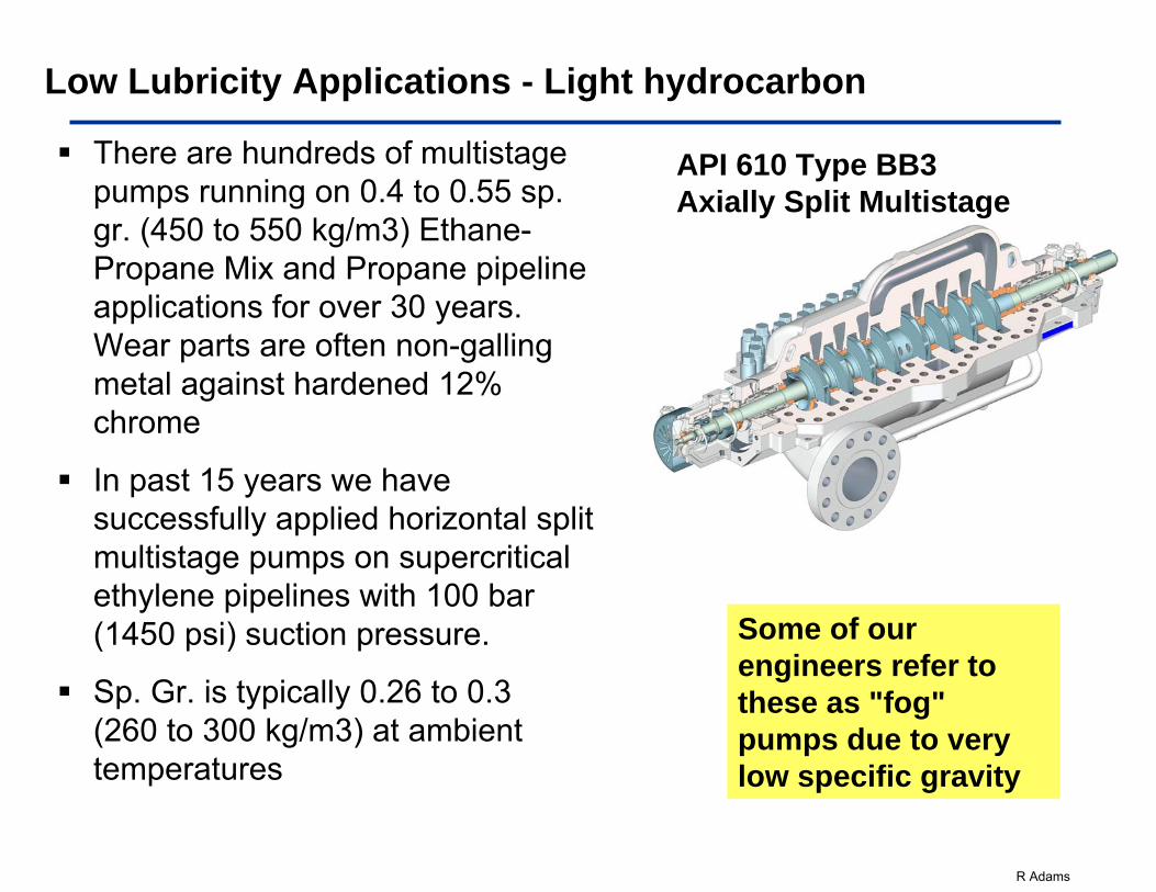
There are hundreds of multistage pumps running on 0.4 to 0.55 sp. gr. (450 to 550 kg/m3) Ethane-Propane Mix and Propane pipeline applications for over 30 years. Wear parts are often non-galling metal against hardened 12% chrome
In past 15 years we have successfully applied horizontal split multistage pumps on supercritical ethylene pipelines with 100 bar (1450 psi) suction pressure.
Sp. Gr. is typically 0.26 to 0.3 (260 to 300 kg/m3) at ambient temperatures
Low Lubricity Applications - Light hydrocarbon
Some of our engineers refer to these as "fog" pumps due to very low specific gravity
API 610 Type BB3 Axially Split Multistage
R Adams
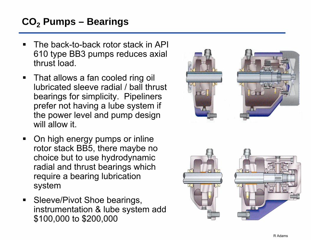
CO2 Pumps – Bearings
The back-to-back rotor stack in API 610 type BB3 pumps reduces axial thrust load.
That allows a fan cooled ring oil lubricated sleeve radial / ball thrust bearings for simplicity. Pipeliners prefer not having a lube system if the power level and pump design will allow it.
On high energy pumps or inline rotor stack BB5, there maybe no choice but to use hydrodynamic radial and thrust bearings which require a bearing lubrication system
Sleeve/Pivot Shoe bearings, instrumentation & lube system add $100,000 to $200,000
R Adams
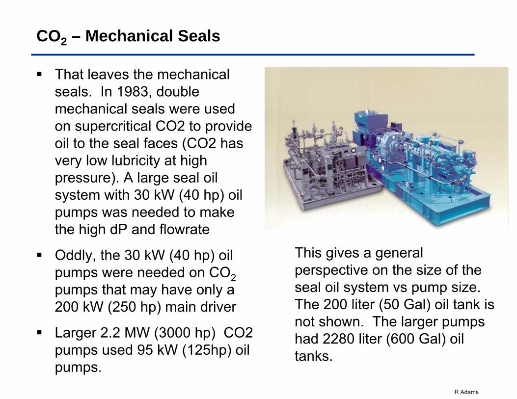
That leaves the mechanical seals. In 1983, double mechanical seals were used on supercritical CO2 to provide oil to the seal faces (CO2 has very low lubricity at high pressure). A large seal oil system with 30 kW (40 hp) oil pumps was needed to make the high dP and flowrate
Oddly, the 30 kW (40 hp) oil pumps were needed on CO2pumps that may have only a 200 kW (250 hp) main driver
Larger 2.2 MW (3000 hp) CO2 pumps used 95 kW (125hp) oil pumps.
CO2 – Mechanical Seals
This gives a general perspective on the size of the seal oil system vs pump size. The 200 liter (50 Gal) oil tank is not shown. The larger pumps had 2280 liter (600 Gal) oil tanks.
R Adams
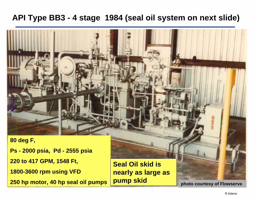
API Type BB3 - 4 stage 1984 (seal oil system on next slide)
80 deg F,
Ps - 2000 psia, Pd - 2555 psia
220 to 417 GPM, 1548 Ft,
1800-3600 rpm using VFD
250 hp motor, 40 hp seal oil pumps photo courtesy of Flowserve
Seal Oil skid is nearly as large as pump skid
R Adams
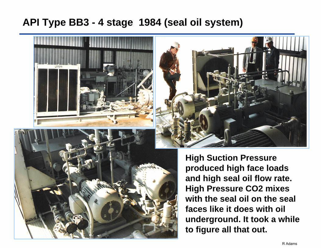
API Type BB3 - 4 stage 1984 (seal oil system)
High Suction Pressure produced high face loads and high seal oil flow rate. High Pressure CO2 mixes with the seal oil on the seal faces like it does with oil underground. It took a while to figure all that out.
R Adams
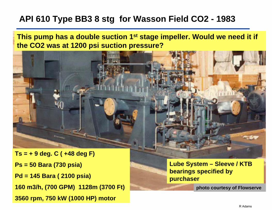
API 610 Type BB3 8 stg for Wasson Field CO2 - 1983
Ts = + 9 deg. C ( +48 deg F)
Ps = 50 Bara (730 psia)
Pd = 145 Bara ( 2100 psia)
160 m3/h, (700 GPM) 1128m (3700 Ft)
3560 rpm, 750 kW (1000 HP) motor
Lube System – Sleeve / KTB bearings specified by purchaser
photo courtesy of Flowserve
This pump has a double suction 1st stage impeller. Would we need it if the CO2 was at 1200 psi suction pressure?
R Adams
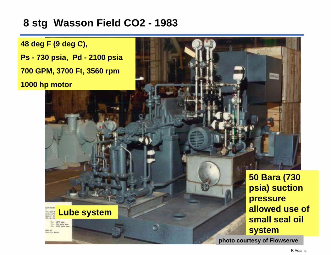
8 stg Wasson Field CO2 - 1983
48 deg F (9 deg C),
Ps - 730 psia, Pd - 2100 psia
700 GPM, 3700 Ft, 3560 rpm
1000 hp motor
50 Bara (730 psia) suction pressure allowed use of small seal oil system
Lube system
photo courtesy of Flowserve
R Adams
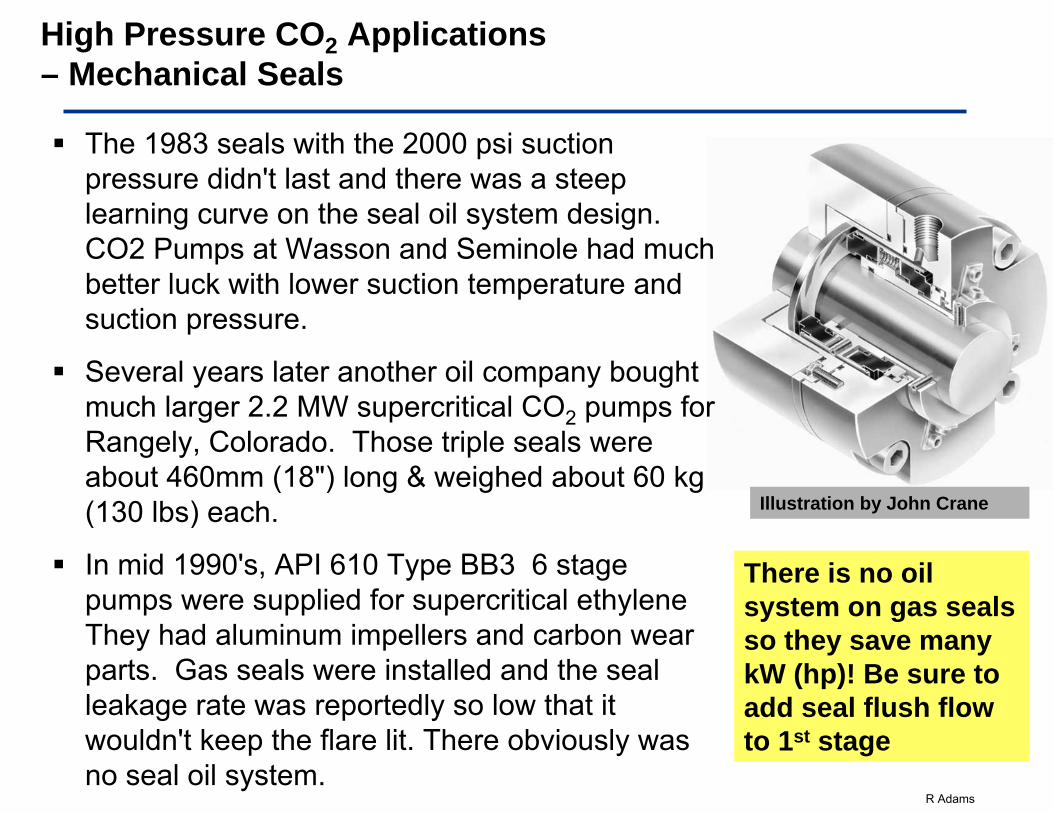
The 1983 seals with the 2000 psi suction pressure didn't last and there was a steep learning curve on the seal oil system design. CO2 Pumps at Wasson and Seminole had much better luck with lower suction temperature and suction pressure.
Several years later another oil company bought much larger 2.2 MW supercritical CO2 pumps for Rangely, Colorado. Those triple seals were about 460mm (18") long & weighed about 60 kg (130 lbs) each.
In mid 1990's, API 610 Type BB3 6 stage pumps were supplied for supercritical ethylene They had aluminum impellers and carbon wear parts. Gas seals were installed and the seal leakage rate was reportedly so low that it wouldn't keep the flare lit. There obviously was no seal oil system.
High Pressure CO2 Applications – Mechanical Seals
There is no oil system on gas seals so they save many kW (hp)! Be sure to add seal flush flow to 1st stage
Illustration by John Crane
R Adams
Since that time more API 610 type BB3 pump with 10 to 12 stages have been applied on supercritical ethylene. They also use gas seals and have been running for many years now.
In 1993, Mobil converted an old API type BB3 pipeline pump to CO2 service. The service center converted it to carbon wear parts, beefed up the flanges and installed gas seals. It is still in Sundown, Texas on supercritical CO2
In late 1990's we converted the dual seals in the Salt Creek 12 stage CO2 injection pumps, to gas seals and deleted the seal oil systems. They are still in service. The oil system was eliminated and seal maintenance reduced measurably.
Similar gas seal systems have become the norm
CO2 Applications – Mechanical Seals
R Adams
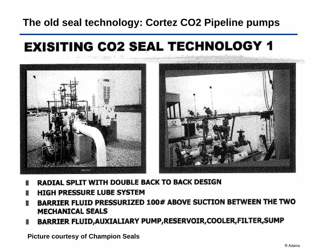
The old seal technology: Cortez CO2 Pipeline pumps
Picture courtesy of Champion Seals
EXISITIIING c.o2 .sE_AL TECHNOLOGY 1 0 --.: : . . _.~ . • ••
I RADIAL SPLIT WI'TH DOU:B.LE BA.CK T01 BACK DESIGN
I HIGH PRESSURE LUBE SYSTEIM I BARRIER FLU~ID PRE.SSURJZED 100# ABOVE S·UCTION BIETWEEN THII! TWO
MECHANICAL ~SEALS
I BARR_IE'R FLUID,AUXIALIARY PUMP,RII!SI!RVOJR,COOLER,FI:LTER,SUMP
R Adams
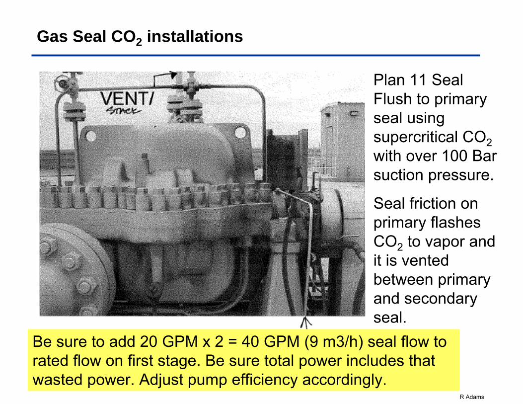
Gas Seal CO2 installations
Plan 11 Seal Flush to primary seal using supercritical CO2with over 100 Bar suction pressure.
Seal friction on primary flashes CO2 to vapor and it is vented between primary and secondary seal.
Be sure to add 20 GPM x 2 = 40 GPM (9 m3/h) seal flow to rated flow on first stage. Be sure total power includes that wasted power. Adjust pump efficiency accordingly.
R Adams
Not all Gas Seals are the same….
• For super critical CO2, seals that work at temperatures less than critical temperature, may not be so successful at higher temperatures.
• Be sure to discuss the application with seal manufacturers.
• Be sure to give them the gas constituents. A little nitrogen and methane can make a big difference in pump and seal performance
• Be sure to give them the suction temperature range, the suction pressure range, rpm range, and shaft size. All can have an effect on seal selection.
• Be sure to ask them for the required seal flush flow and pressure to each seal. Since most CO2 pumps have 2 seals, add that flow to the rated flow for number of stages needed to achieve the seal flush pressure. Correct pump power accordingly.
New Construction pipeline dirt can destroy seal faces.
Invest in high pressure dual seal flush filters.
One can be cleaned while the other is running.
R Adams
Understand the Thermodynamics – Suction pressures in 86-150 Bar (1250 to 2100 psia) at 26-35C (80-90F) are common. Bubble size near critical pressure is microscopic, so Ps excursion down to about 76 Bar (1100 psi) can be tolerated. NPSH is not a consideration since cavitation is impossible above critical pressure.
• In N. America, use BB3 (Axial split Multistage) type if it will handle MAWP & MASP. Otherwise, use radially split Type BB5. On high energypumps, they may be direct drive, or high speed, BB5 with bearing lube system
Due to low lubricity pay attention to Rotor Construction – Avoid lots of stages on inline rotor stack. Specify non-galling metals, Carbon, or PEEK, vs hardened 12% chrome wear parts. 12% Chrome vs 12% Chrome will not work.
Check rotor dynamics with 2 x clearances and check for acoustic resonances at all speed, temperature and pressure combinations
Use liquid or gas seals with a track record. Do not use gas seals with N2 injection on cold /subcritical pressure services as gas will affect NPSH
Supercritical CO2 ApplicationsSummary
R Adams
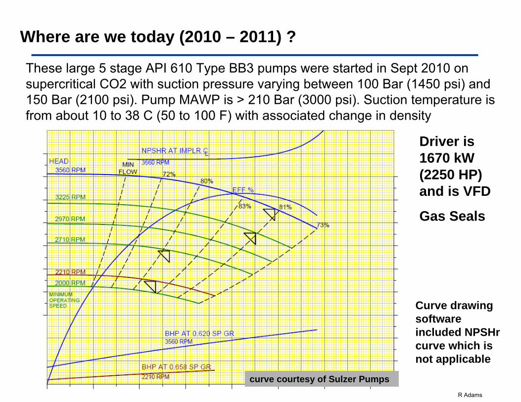
These large 5 stage API 610 Type BB3 pumps were started in Sept 2010 on supercritical CO2 with suction pressure varying between 100 Bar (1450 psi) and 150 Bar (2100 psi). Pump MAWP is > 210 Bar (3000 psi). Suction temperature is from about 10 to 38 C (50 to 100 F) with associated change in density
Where are we today (2010 – 2011) ?
Driver is 1670 kW (2250 HP) and is VFD
Gas Seals
Curve drawing software included NPSHr curve which is not applicable
curve courtesy of Sulzer Pumps
R Adams
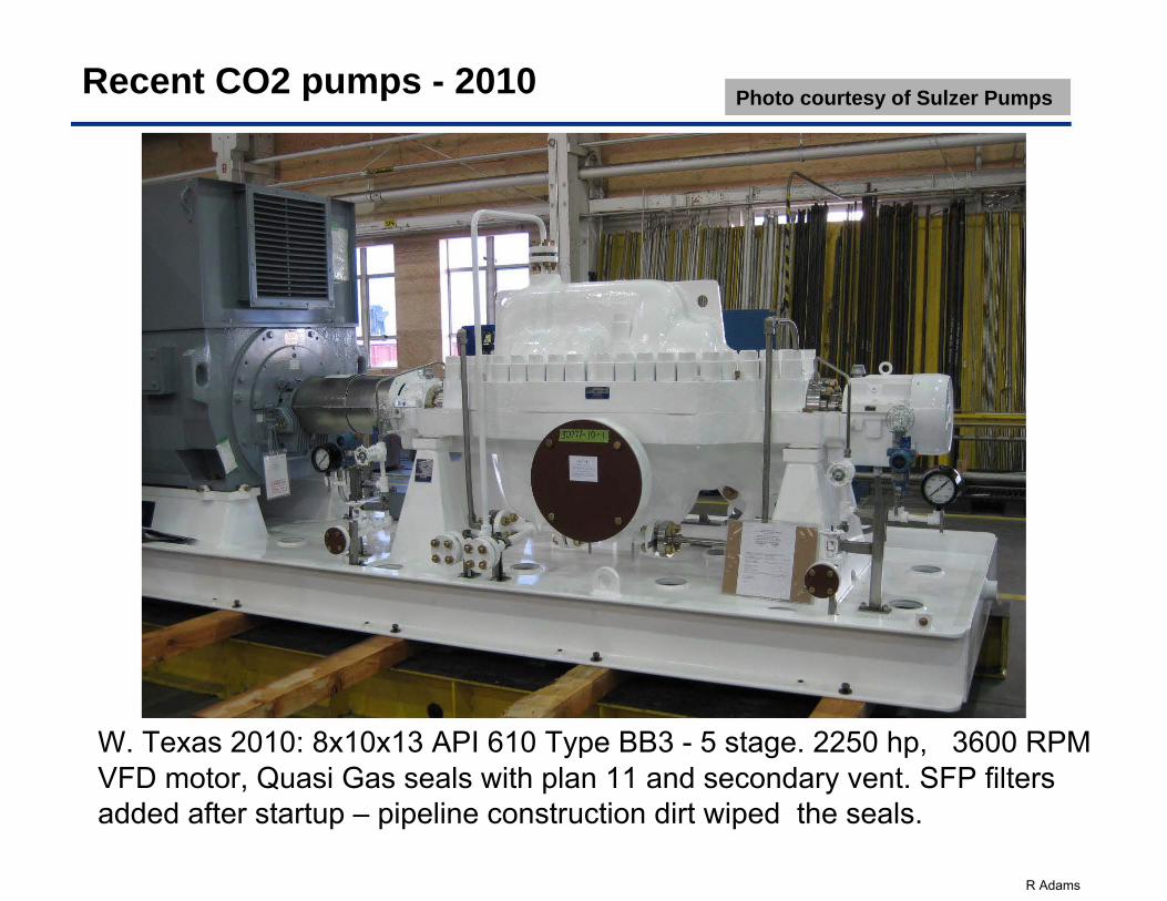
Recent CO2 pumps - 2010
W. Texas 2010: 8x10x13 API 610 Type BB3 - 5 stage. 2250 hp, 3600 RPM VFD motor, Quasi Gas seals with plan 11 and secondary vent. SFP filters added after startup – pipeline construction dirt wiped the seals.
Photo courtesy of Sulzer Pumps
R Adams
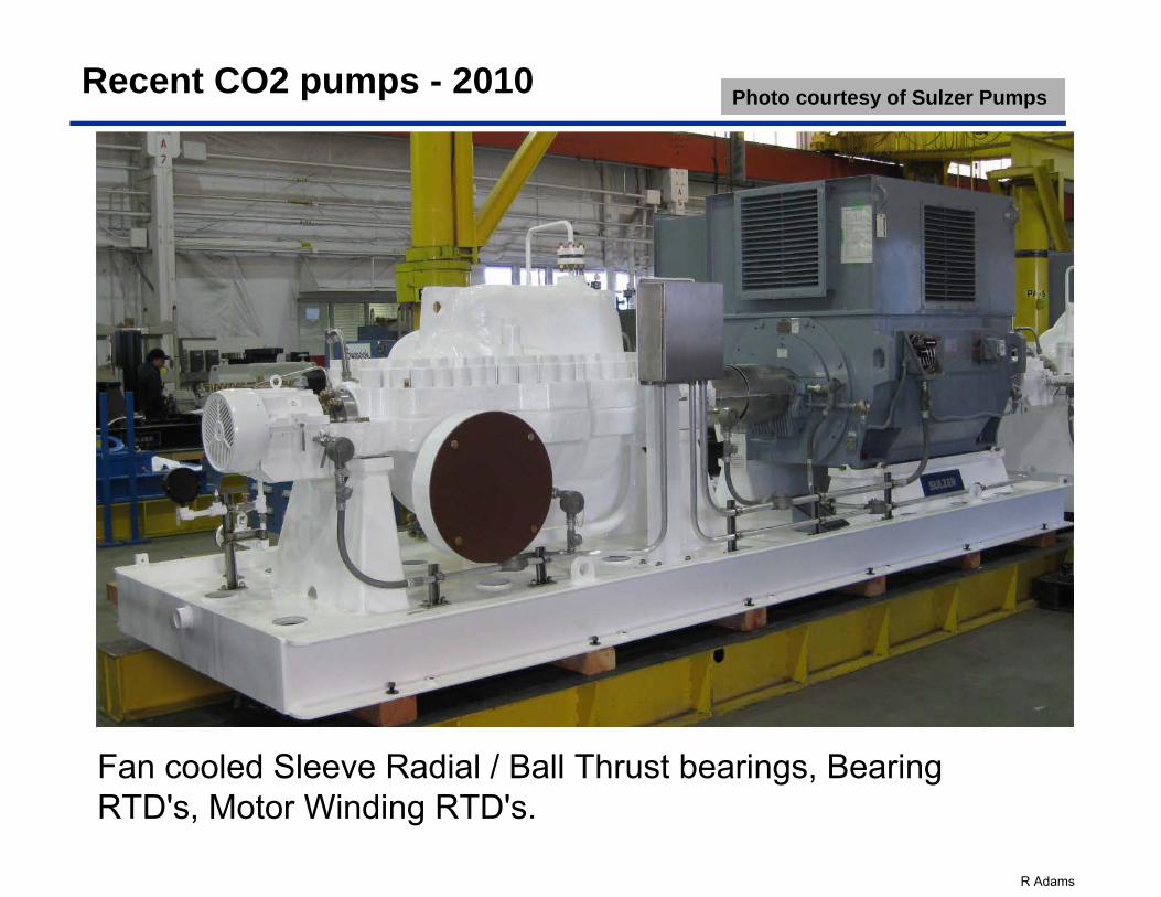
Recent CO2 pumps - 2010
Fan cooled Sleeve Radial / Ball Thrust bearings, Bearing RTD's, Motor Winding RTD's.
Photo courtesy of Sulzer Pumps
R Adams
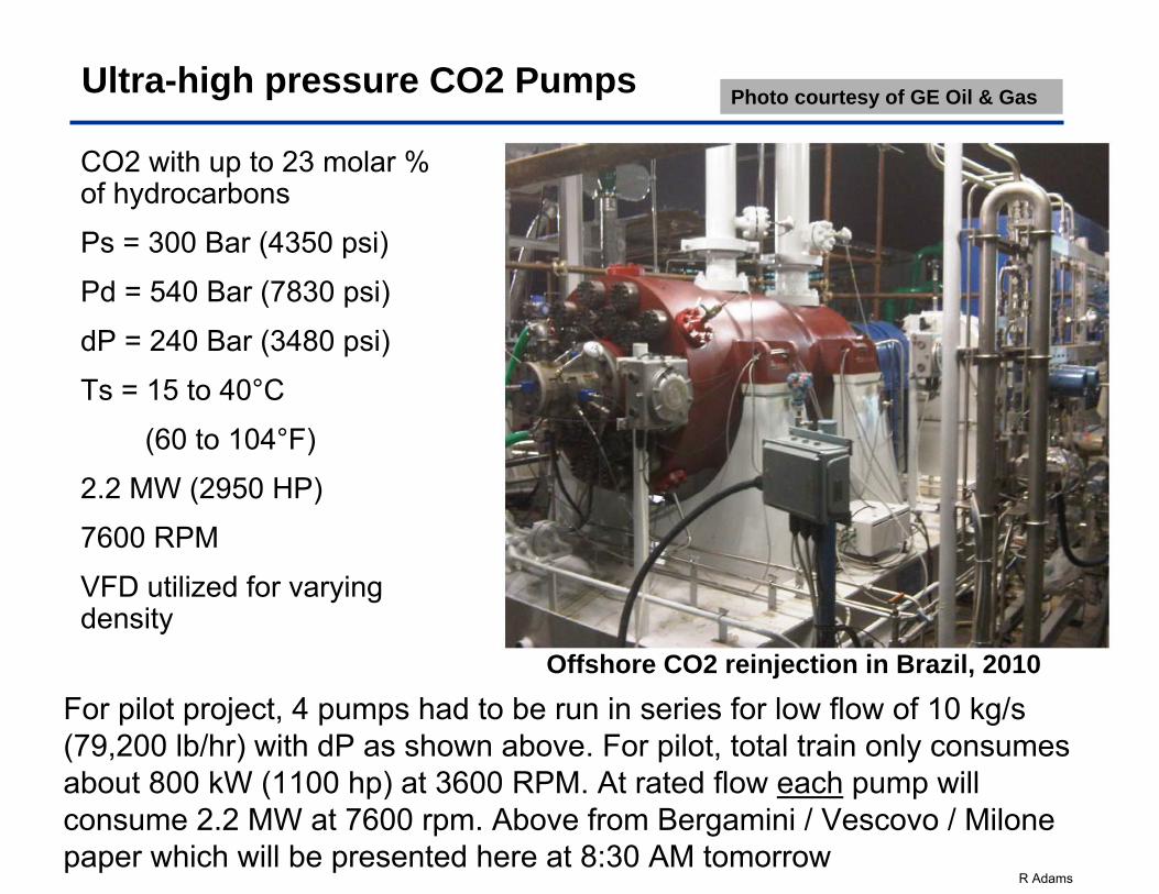
Ultra-high pressure CO2 Pumps
CO2 with up to 23 molar % of hydrocarbons
Ps = 300 Bar (4350 psi)
Pd = 540 Bar (7830 psi)
dP = 240 Bar (3480 psi)
Ts = 15 to 40°C
(60 to 104°F)
2.2 MW (2950 HP)
7600 RPM
VFD utilized for varying density
Photo courtesy of GE Oil & Gas
Offshore CO2 reinjection in Brazil, 2010
For pilot project, 4 pumps had to be run in series for low flow of 10 kg/s (79,200 lb/hr) with dP as shown above. For pilot, total train only consumes about 800 kW (1100 hp) at 3600 RPM. At rated flow each pump will consume 2.2 MW at 7600 rpm. Above from Bergamini / Vescovo / Milone paper which will be presented here at 8:30 AM tomorrow
R Adams
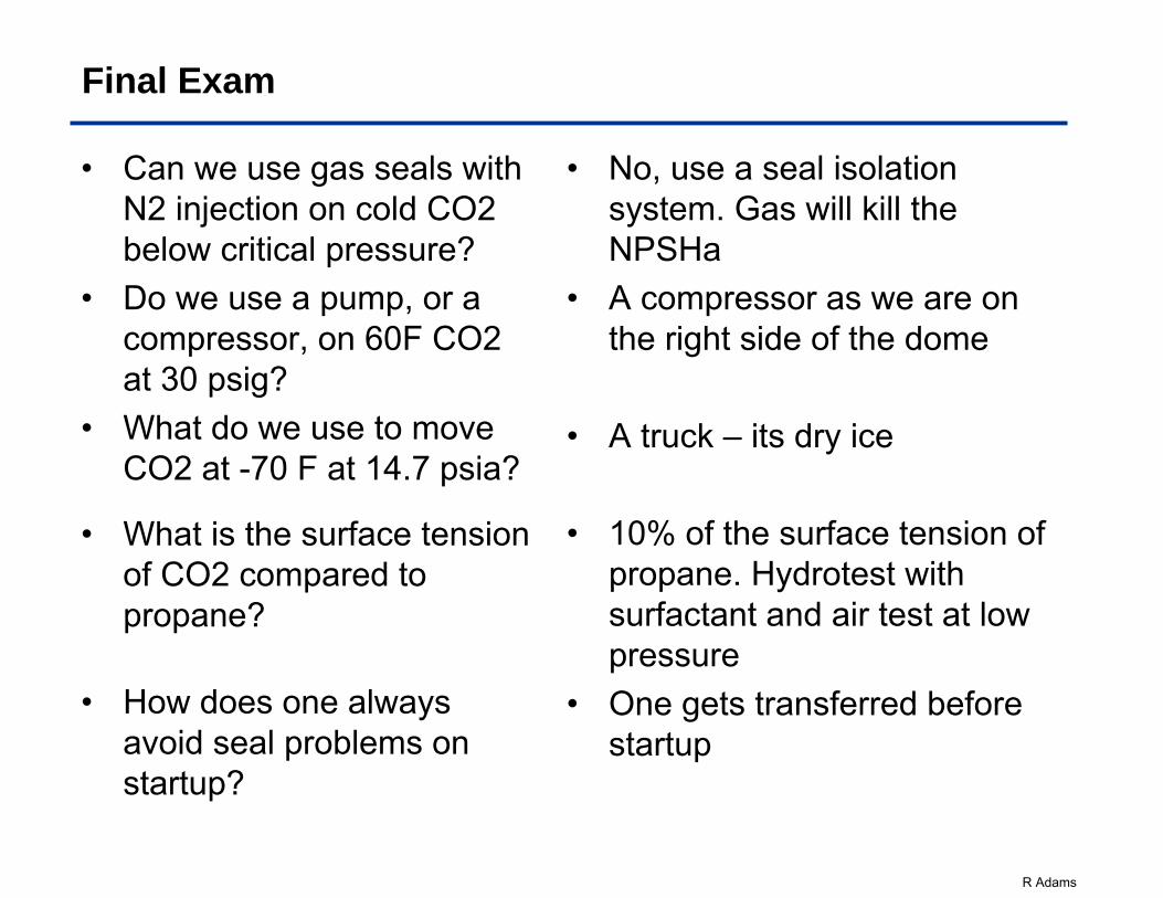
Final Exam
• Can we use gas seals with N2 injection on cold CO2 below critical pressure?
• Do we use a pump, or a compressor, on 60F CO2 at 30 psig?
• What do we use to move CO2 at -70 F at 14.7 psia?
• What is the surface tension of CO2 compared to propane?
• How does one always avoid seal problems on startup?
• No, use a seal isolation system. Gas will kill the NPSHa
• A compressor as we are on the right side of the dome
• A truck – its dry ice
• 10% of the surface tension of propane. Hydrotest with surfactant and air test at low pressure
• One gets transferred before startup
R Adams
CO2
Thank you for your attention.
Questions??