Embed Size (px)
Citation preview
CNEHeat Rejection Capacity 147 to 5000 kW
ÁoÃhLU ÁIÀ n¼vºHk¹¨
Evaporative Condensers
1
ÏI@w ®@¿a pH y@ÃM I@M
nj o@ÄmQIº «Tvi » IļQ » o«{°U ½nH¼µÀ ·Izinj ¾£MIw
» jI@µ\ºH » ÁpI@wI¶ow S÷¹Å ÁI¿Än»A ¸Î ¸ÄoiA Jm]
,Â@ÄI@õÃ{,Â@ÄHm@ü R¯¼@~d¶ Án»A ®@µø Â@±Äk@LU ÍÄI¹Å
·HoÄH ·I¶qÄqø n¼z¨ nj I¿ºA ¾M ·kÃzhM SùÃø » ÂT÷¹Å
.k{ILö I{¼¨
·k@ºI@wn p»n ¾@M ¸@µò
S@ÄHk@À » Áq@Än ¾@¶I@ºo@M IM ½HoµÀ ,j¼i ¦Är¼²¼¹§U ·H¼U
¸@ë¹w Â@Tò¼@Fv¶ ,o@TzÃM ¾@ao@À Án» ½o@¿M Á¼w ¾M ·A
Í@@]Ho@@¶ ϼ@@L¤ ®@@MI@@¤ » o@@Uo@M S@Ãÿè ¾@M ·k@Ãwn S@¿]
j¼@@i x»j o@@M Â@@±±µ²H ¸@ÃM » Â@±¶ c@õw nj jnHk@ºI@TwH
.k¹¨ ¶ tIveH
pH ÁH ¾@ÄI@¶o@w I@M
o@ÿº ½I@\¹Q»k@~§Ä pH y@ÃM Á»o@ú I@M » ¾@Mo@\U ¾@Àj nI@¿a
» Â@@Tw»j pH nI@@{o@@w Â@@ÄI@@ñÎ nj » ½k@@Äpn» }@~hT¶
ÁI@À ¾@TwH¼@i » RI@Äo@ʺ I@U k@{¼@¨ Â@¶ ¾ºIµÃµÅ ,SÄk]
¾@M ¾@]¼@U I@M n¼z¨ pH ZnIi » ®iHj nj Hn ³oTd¶ ·IÄoTz¶
xo@Tv¬ ¾@M ®@ú nj » jpIw ½jn»AoM kÄoLU S÷¹Å ϼÅH
,nI@¨jk@¶ ,nI@Ä ,Án»Aj¼@w » Án» ½o@¿M ,ÁjI~T¤H ¢º»n »
.k{IM j¼i ¶Ho¬ ·IÄoTz¶ ·ILÃTzQ » n»Iz¶
¢@@º»n » xo@Tv¬ nj o@Y¼@¶ Â@±¶I@ø I@¶ x°@U S@wH k@öH
¾@@£õ¹¶ nj n¼@@z¨ Â@T÷¹Å Ï°@£TwH » ¾@÷w¼@U » ÁjI@~T¤H
.k{IM
Â@UnHo@e » Â@Uj»o@M S@¨o@{
Â@UnHo@e » Â@Uj»oM S¨o{
Â@UnHoe » ÂUj»oM S¨o{·¼¹¨H
S@ÄoÄk¶ Âz¶ ôi S@¨o@{
The . with over 40
years of continuous experience and tireless
perseverance in linking itself with latest
technology prevailing in the freezing and chilling of
agro-food industries including the industrial and
petrochemical industries, believes in the policy of
Islamic Republic of Iran.
While keeping abreast of tomorrow's technology,
The . updates its production and
operation goal in nurturing optimization and feels
a heavy task in meeting the quality assurance
commitment, duly conforming to the national and
international standards of authoritative bodies.
Backed by experience of four decades and with
continuous support of illustrious workforce of 150
expert personnel, the . in an
atmosphere of friendship and dedication,
sincerely strives to gain the confidence and
satisfaction of national and international
customers, simultaneously adapting to updated
requirements of refrigeration industry, thus
advocating it's customers in the development of
economic achievements and thereby maximizing
profit. It is anticipated that our search for
excellence would be proved effective in the
economic development toward industrial
independence in the middle east region.
Broodati & Hararati Co
B&H Co
B&H Co
.
The Management Trait
1
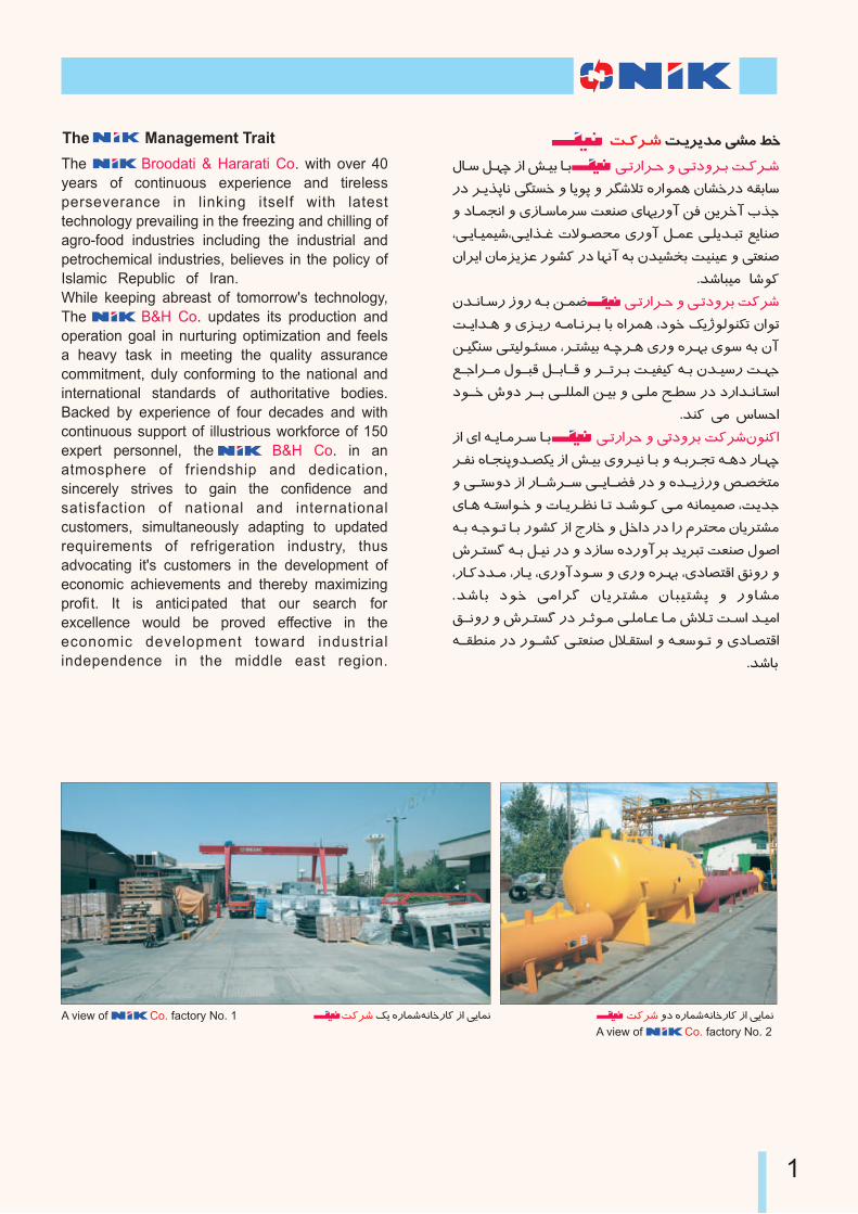
S¨o{ ¦Ä ½nIµ{¾ºIinI¨ pH ÂÄIµºA view of factory No. 1Co. S¨o{ ½nIµ{¾ºIinI¨ pH ÂÄIµº»j
A view of factory No. 2Co.
GENERAL
evaporative condensers are used to
condense refrigerant gas in industrial
processes, refrigeration systems and air
conditioning. Comprising more than 40 models
and a wide range of capacities they respond to
all installation requirements.
CNE
RIñ¨
nj jo@L¶ pI@¬ o@Ãõ£U ÁHo@M Áo@ÃhLU ÁI@Àn¼vºHk¹¨
¾@M ̼@Lõ¶ ¾Ä¼¿U » kÄoLU ÁIÀ ´TvÃw ,ÂT÷¹Å ÁIÀk¹ÄAoÎ
pH Â@@÷Ãw» ½o@Tv¬ » Ïk@¶ 40 pH y@ÃM I@M » k@º»n Â@¶ nI@¨
.k¹{IM ¶ ÂUIvÃwIU ÁIÀpIú ¾µÀ Á¼«hwIQ SÃÎoË
CNE
PERFORMANCE PRINCIPLE
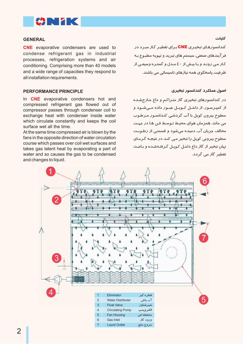
In evaporative condensers hot and compressed refrigerant gas flowed out of compressor passes through condenser coil to exchange heat with condenser inside water which circulate constantly and keeps the coil surface wet all the time. At the same time compressed air is blown by the fans in the opposite direction of water circulation course which passes over coil wet surfaces and takes gas latent heat by evaporating a part of water and so causes the gas to be condensed and changes to liquid.
CNE
.
ÁoÃhLU n¼vºHk¹¨ jo§±µø ϼÅH
½k@{ZnI@i ùHj » ´@¨Ho@T¶ pI¬ ÁoÃhLU ÁIÀn¼vºHk¹¨ nj
» j¼@@{Â@@¶ ½jHj n¼@@Lø ®@@ļ@@¨ ®@@iHj pH ,n¼@wo@Pµ¨ pH
J¼@öo@¶ n¼@vºHk@¹¨ Â@{jo¬ JA IM ®Ä¼¨ ·»oÃM b¼õw
S@¿] nj I@À ¸@Î ô@w¼@U ô@Ãd¶ ÁH¼À ·I¶qµÀ ,kºI¶ ¶
S@M¼@ön pH Â@Tµv¤ » j¼{¶ ½köj JA ·IÄo] þ²Ih¶
ÁI@¶o@¬ ¾@\ÃTº nj k@¹¨ Â@¶ oÃhLU Hn ®Ä¼¨ º»oÃM b¼õw
W@øI@M » ½k@{¾@TÎo@¬ ®@ļ@¨ ®@iHj ùHj pI¬ pH oÃhLU ·I¿º
.jjo¬ ¶ pI¬ oÃõ£U
2
oì ½oõ¤
xIQ JA
n»I¹{oÃ{
OµQ»oT§²H
¸Î ¾Êÿd¶
pI¬ j»n»
ÍÄI¶ Z»oi
Eliminator
Water Distributer
Float Valve
Circulating Pump
Fan Housing
Gas Inlet
Liquid Outlet
1
2
3
4
5
6
7
COIL
Coil is made of special high efficiency steel
tubes and its compact design is so that
produces highest heat transfer coefficient.
Tubes slope grade is in such a way that
facilitates condensed refrigerant and oil drain-
age.
The coil is hot dip galvanized after fabrication
and tested at 30 bar air pressure three times
prior to galvanization and once after the process
against shock and leakage effect to eliminate
leakage probability for many years to come .
.
.
PAN
All evaporative condensers pans are
completely made of galvanized sheets in
suitable shapes and dimensions and without
vibration. In addition, the whole condenser
structure is hot galvanized after fabrication.
No type of welding is used in connection of
different parts together to protect galvanized
layer. Using proper galvanized bolts and nuts
removes the probability of leakage completely.
There are two access doors on both sides of the
pan to ease access to pan for cleaning and
repair purposes. Water filter prevents foreign
objects from entering in to the pump. Easy
drainage and suitable level of pan water are
other special advantages of evaporative
condensers.
CNE
CNE
.
FAN AIR SUPPLY
evaporative condensers air supply system is equipped with centrifugal fans, which are very workable and practicable. Dynamic balance is done by computerized devices, which prevents noise, vibration and being worn out. Each fan has its own electromotor separately to prevent condenser operation stoppage while being under repair. Furthermore, to control the capacity, it would be possible to take one or two fans out of the cycle. Belt adjustment with electromotor bracket (stand) is done very easily. The points to be greased are perfectly accessible. Fans are located inside the condenser in such a way they are protected from outlet air moisture, wind and rain.
CNE
.
.
.
®Ä¼¨
bo@ö » j¼@{Â@¶ ¾TiIw |¼~h¶ Áj¯¼Î ¾²¼² pH ®Ä¼¨
ÏI@£TºH K@Äo@ò ¸@Äo@U¯I@M ¾@¨ SwH ÁH ¾º¼¬ ¾M ·A ½jozÎ
¾@M I@À ¾@²¼@² Ák@¹M K@Ã{» jn»A Â@¶ j¼@]» ¾M Hn RnHoe
¾@M ¸@ü»n » ½k@{o@Ãõ£U jo@L¶ ¾@ñhU ¾@¨ S@wH Â@Un¼@Å
I@M ·k@{¾@TiI@w pH k@÷M ®@ļ@¨ .jo@ì Â@¶ Rn¼Å ºIwA
¾@±eo@¶ ¾@w nj » jjo@¬ Â@¶ ³o@¬ ½qú¼²I¬ Á¯IM S¶Ihò
nI@zÎ I@M ·A pH k@÷M ¾@±eo@¶ ¦@Ä » ·¼@ÃwHq@úH¼@²I@¬ pH ®L¤
ÁHo@M I@U jo@ì ¶ nHo¤ ÂTzº » ¥¼{ ·¼¶pA jn¼¶ nIM 30
.k{ILº ̧ ÃM nj ÂTzº ÏIµTeH ¾º¼«`ÃÀ ÁjIµT¶ ÁI¿²Iw
¦TzU
ÁI@@¿¤n» pH ÓI@@¶I@@µU Áo@@ÃhLU ÁI@Àn¼@vºHk@¹¨ ¦@TzU
¾@TiI@w xI@÷UnH k@ò» K@wI@¹¶ jI÷MH » ÏI§{H nj ½qúH¼²I¬
S@iI@w pH k@÷M n¼@vºHk@¹¨ o@`¨Ho@TwH ³I@µU » j¼@{Â@¶
½q@úH¼@²I@¬ pH k÷M I¿ºA ÏI~UH nj» jjo¬ ¶ ³o¬ ½qúH¼²I¬
É@ÎI@d¶ ¾@į I@U j¼@{Â@µº ½jI@ÿTwH ÁnI§{¼] pH ½I¬ _ÃÀ
ÁI@À ½o¿¶ » _ÃQ » KwI¹¶ Áoìpnj .j¼{Éÿe ½qúH¼²I¬
¦@TzU .jo@M ¶ ¸ÃM pH Hn ÂTzº ¾º¼¬ oÀ ·I§¶H , ½qúH¼²I¬
¾@M ÂwoTwj » k{IM ¶ ýoö »j pH kÄjpIM ¾`Änj ÁHnHj
,S@wH ·IwA SÎIʺ » oõ÷U ¾º¼¬ oÀ S¿] ·A ÁI] ¾µÀ
Áoì¼±] OµQ ¾M ¥I{Ii » nIi j»n» pH j¼]¼¶ JA oT±ÃÎ
.jn»A ¶ ®µø ¾M
pH ¦@TzU JA ½k@{JI@ve » Swnj ÌIÿUnH » ·IwA ¾Ã±hU
. SwH n¼vºHk¹¨ o«Äj ÁI¿Ã¬sÄ»
CNE
CNE
ÂÀj H¼À ́ TvÃw
ÁI@¿¹Î ¾@M q@¿\¶ ÁI@Àn¼@vºHk@¹¨ Â@Àj H¼@À ´TvÃw
I@M Â@§Ã¶I@¹Äj u@º¯I@M , S@wH k@¶AnI@¨ nI@ÃvM » r¼@ÃÎo@TºIw
¾@º¼@¬o@À Í@ºI@¶ ¾@¨ j¼@{Â@¶ ³I@\ºH Áo@U¼@ÃP¶I@¨ ½I@«Twj
o@À .jjo@¬ ¶ tnj»p ¬j¼woÎ » xI÷UnH , HkÅ»ow
I@¿ºA o@õ÷U ·I¶p nj IU SwH Hq\¶ n¼U¼¶»oT§²H ÁHnHj ¸Î
S@¿] ·H¼@U Â@¶ ¸Ã¹`µÀ .j¼zº ¾ÿ¤»nIaj n¼vºHk¹¨ nI¨
´@ÃʹU ,jo@¨ ZnI@i nHk@¶pH Hn ¸Î »j IÄ ¦Ä SÃÎoË ÏoT¹¨
½jI@w nI@ÃvM I@Àn¼@U¼@¶»o@T§²H |¼@~h¶ ¾@ÄI@Q I@M IÀ ¾µvU
ÂÀjI] .kºnHjnHo¤ toTwj nj °¶I¨ IÀn¼i uÄo¬ » SwH
ÁH¼@À SM¼ön pH ¾¨ SwH ÁH ¾º¼«M ½I«Twj nj IÀ ¸Î
.SwH ·I¶H nj ·HnIM » jIM » Â]»oi
CNE
3
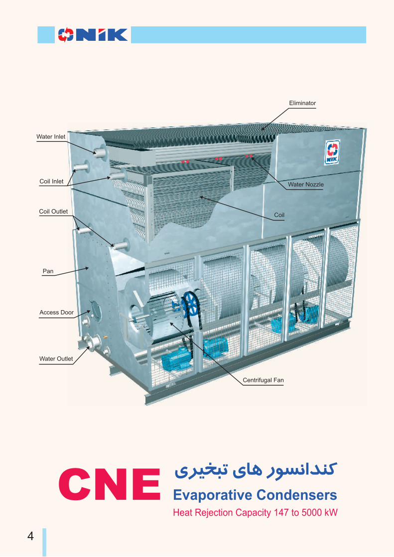
Water Nozzle
Eliminator
Water Inlet
Coil
Access Door
Pan
Water Outlet
Centrifugal Fan
CNEHeat Rejection Capacity 147 to 5000 kW
ÁoÃhLU ÁIÀ n¼vºHk¹¨
Evaporative Condensers
4
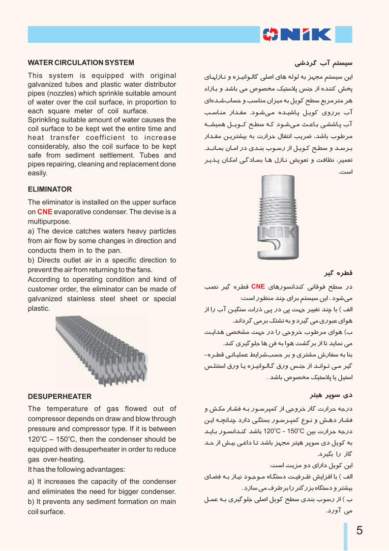
WATER CIRCULATION SYSTEM
This system is equipped with original galvanized tubes and plastic water distributor pipes (nozzles) which sprinkle suitable amount of water over the coil surface, in proportion to each square meter of coil surface. Sprinkling suitable amount of water causes the coil surface to be kept wet the entire time and heat transfer coeff icient to increase considerably, also the coil surface to be kept safe from sediment settlement. Tubes and pipes repairing, cleaning and replacement done easily.
.
ELIMINATOR
The eliminator is installed on the upper surface
on evaporative condenser. The devise is a
multipurpose.
a) The device catches waters heavy particles
from air flow by some changes in direction and
conducts them in to the pan.
b) Directs outlet air in a specific direction to
prevent the air from returning to the fans.
According to operating condition and kind of
customer order, the eliminator can be made of
galvanized stainless steel sheet or special
plastic.
CNE
.
.
.
DESUPERHEATER
The temperature of gas flowed out of
compressor depends on draw and blow through
pressure and compressor type. If it is between o o120 C – 150 C, then the condenser should be
equipped with desuperheater in order to reduce
gas over-heating.
It has the following advantages:
a) It increases the capacity of the condenser
and eliminates the need for bigger condenser.
b) It prevents any sediment formation on main
coil surface.
.
Â{jo¬ JA ´TvÃw
ÁI@¿²pI@º » ½q@úH¼@²I¬ ±ÅH ÁIÀ ¾²¼² ¾M q¿\¶ ´TvÃw ¸ÄH
EHpI@M » k{IM ¶ |¼~h¶ ¦ÃTw°Q u¹] pH ½k¹¹¨ yhQ
ÁH½k@{JIve » KwI¹¶ ·Hqö ¾M ®Ä¼¨ cõw ÍMo¶oT¶ oÀ
K@wI@¹¶ nHk@£¶ .j¼@{Â@¶ ½k@Ã{I@Q ®@ļ¨ Á»noM JA
¾@@zõÀ ®@@ļ@@¨ c@õw ¾@¨ j¼@{Â@¶ W@øI@M Â@z{I@Q JA
nHk@£¶ ¸@ÄoTzÃM ¾M RnHoe ÏI£TºH KÄoò ,k{IM J¼öo¶
.k@@ºI@µM ·I@¶H nj Ák@¹M J¼@wn pH ®@ļ@¨ c@õw » k@wo@M
o@Äm@Q ·I@§¶H Â@¬jI@vM I@À ÏpI@º Çļ÷U » SÎIʺ ,oõ÷U
.SwH
oì ½oõ¤
K~º oì ½oõ¤ ÁIÀn¼vºHk¹¨ ºI¤¼Î cõw nj
:SwH n¼Ê¹¶ k¹a ÁHoM ´TvÃw ¸ÄH , j¼{¶
pH Hn JA ¸@ë¹w RHnl Â@Q nj ÂQ S¿] oÃÃûU k¹a IM ( þ²H
.kºHjo¬ ¶oM ¦TzU ¾M » joì ¶ Án¼Lø ÁH¼À
S@ÄHkÀ Â~hz¶ S¿] nj Hn Â]»oi J¼öo¶ ÁH¼À (J
.k¹¨ Áoì¼±] IÀ ¸Î ¾M H¼À Sz¬oM pH IU kÄIµº ¶
-½o@õ¤ Â@UI@ñµø ôÄHo{Kve oM » ÁoTz¶ xnIÿw ¾M I¹M
u@±¹TwH ¡n» I@Ä ½q@úH¼@²I@¬ ¡n» u@¹] pH k@ºH¼@U Â@¶ oì
. k{IM |¼~h¶ ¦ÃTw°Q IÄ ®ÃTwH
CNE
oTÃÀ oQ¼w Áj
» y@§¶ nI@zÎ ¾@M n¼@woPµ¨ pH Â]»oi pI¬ RnHoe ¾]nj
¸@ÄH ¾@`ºI@¹a jnHj Â@«TvM n¼@wo@Pµ¨ ̼@º » y@Àj nI@zÎo ok@ÄI@M n¼@vºHk@¹¨ k{IM 120 C - 150 C ¸ÃM RnHoe ¾]nj
k@e pH y@ÃM Â@üHj I@U k{IM q¿\¶ oTÃÀ oQ¼w Áj ®Ä¼¨ ¾M
.joëM Hn pI¬
:SwH SÄq¶ »j ÁHnHj ®Ä¼¨ ¸ÄH
ÁI@ñÎ ¾@M pI@ú j¼@]¼@¶ ½I@«Twj S@ÃÎo@Ë yÄHqÎH IM ( þ²H
. jpIw ¶ ýoöoM Hn oT¬nqM ½I«Twj » oTzÃM
®@µø ¾@M Áoì¼±] ±ÅH ®Ä¼¨ cõw Ák¹M J¼wn pH ( J
.jn»A ¶
5

ModelNominal Capacity
Without Desuperheater With Desuperheater
162
194
242
256
300
320
286
333
396
432
495
510
551
612
658
725
784
880
1027
1152
1276
1510
1614
1468
1804
1424
1520
1741
1805
2100
2206
2385
2558
2750
3288
3608
4052
4411
5116
5500
147
176
210
233
272
291
260
303
360
393
440
465
501
558
598
659
713
799
934
1048
1162
1372
1467
1334
1640
1295
1380
1583
1641
1910
2005
2168
2325
2500
2935
3280
3684
4010
4650
5000
CNE 110
CNE 150
CNE 180
CNE 200
CNE 225
CNE 250
CNE 225L
CNE 250L
CNE 300
CNE 330
CNE 370
CNE 400
CNE 430
CNE 480
CNE 510
CNE 560
CNE 610
CNE 685
CNE 800
CNE 900
CNE 980
CNE 1180
CNE 1260
CNE 1340
CNE 1410
CNE 1110L
CNE 1210L
CNE 1350L
CNE 1410L
CNE 1580L
CNE 1725L
CNE 1865L
CNE 2000L
CNE 2150L
CNE 2520
CNE 2820
CNE 3160
CNE 3450
CNE 4000
CNE 4300
(RH» ¼±Ã¨) n¼vºHk¹¨ ¶Iº SÃÎoË -1Ï»k]
Table 1- Nominal Capacity (kW)
Capacity
Factor
0.876
0.886
0.895
0.904
0.913
0.922
0.931
Suction
oTemp. ( C)
-25
-20
-15
-10
-5
0
5
Suction
Pressure (kPa)
53.9
89.2
135.3
189.3
235
328.5
414.8
oTÃÀoQ¼w Áj ÁHoM b°ÅH KÄoò -2Ï»k]
Table 2- Desuperheater Correction Factor
6
1 Ï»k@] ¢@MIõ¶ ÁI¿²k¶ pH ¦Ä oÀ
:SwH ½k¶A Swj ¾M oÄp ÂUIñµø ôÄHo{nj
oÃõ£U ÁI¶j -1
ôÃd¶ oU ÁI¶j -2
(¥Iú¼¶A) joL¶ ̼º -3
¾@¨ jo@¨ kÀH¼i oÃÃûU SÃÎoË óo{ ¾w pH ¦Ä oÀ oÃÃûU IM
.SwH ½k{ ½jHj bo{ JIhTºH x»n WdL¶ nj
1 Ï»k@] ·¼@Tw ÁI@À SÃÎoËo .k{IM ¶ Te=10 C y§¶ ÁI¶j ¾M ó¼Mo¶
CNE µwH SÃÎoË
:¾]¼UWith Desuperheater
oTc = 38 CoWB = 24 C
NH3
The of each
evaporative condenser mentioned in
table 1, depends on the following operating
conditions:
1- Condensing temperature
2- Ambient wet bulb temperature
3- Type of refrigerant (Ammonia)
If one of these three items changes, the
capacity will change too, which is explained in
selection procedure.
The capacities mentioned in table 1 for
“With Desuperheater” column belongs to oTe=10 C.
Nominal Heat Rejection Capacity
CNE
NOTE:
oTc = 38 CoWB = 24 C
Nh3
S@ÃÎo@Ë Ì¼@µ\¶ I@M o@MHo@M ´TvÃw ¦Ä n¼vºHk¹¨ SÃÎoË
o@M .k{IM ¶ n¼woPµ¨ Án¼U¼¶»oT§²H ·H¼U » IÀn¼UHoQH»H
jo@@L¶ ÁHo@@M Â@@e°@@ÅH K@Äo@ò Â@UI@ñµø ô@ÄHo@{K@ve
Swj ¾M 4 IÄ3 Ï»Hk] pH KÃUoU ¾M R22 pI¬ IÄ ¥Iú¼¶A
S@ÃÎo@Ë ,½k¶A Swj ¾M SÃÎoË nj ·A Joò IM ¾¨ kÄA¶
.j¼{¶ ¾LwId¶ KwI¹¶ n¼vºHk¹¨
nj Hn ¡¼@@Î jk@@ø , o@@TÃÀ o@@Q¼@@w Áj ¾@M pI@ú Rn¼@Ånj
Swj ¾M 2 Ï»k] pH ¾¨ oTÃÀ oQ¼w Áj b°ÅH KÄoò
Ïk@¶ , 1 Ï»k@] ¾M ¾÷]Ho¶ IM SÄI¿º nj ,½jo¨ Joò kÄAÂ@¶
.´Än»A ¶ Swj ¾M Hn KwI¹¶ n¼vºHk¹¨
Â@¨I@ú¼@¶A kÄoLU ´TvÃw ¦Ä Án¼UHoQH»H SÃÎoË oRnHo@e ¾@]nj » -15 C o@ÃhLU RnHo@e ¾@]nj » 640 kW
o .k{IM ¶ 40 C oÃõ£U
o@U ÁI@¶j » 220 kW Án¼@U¼@¶»o@T§²H S@ÃÎo@Ë ¾M ¾]¼U IMopI@ú jn¼@¶ n¼@vºHk@¹¨ k@{I@M ¶ 26 C IM oMHoM ¾¨ ôÃd¶
.jjo¬ ¶ JIhTºH oÄp bo{ ¾M oTÃÀ oQ¼w Áj ¾M q¿\¶
( Án¼UHoQH»H SÃÎoË) ÂUj»oM SÃÎoË
Án¼U¼¶»oT§²H SÃÎoË
½k{ZnIi RnHoe ®¨ nHk£¶ o o 26 C ôÃd¶ oU ÁI¶j » 40 CoÃõ£U ÁI¶j ÁHoM 3Ï»k] pH
0.97 = SÃÎoË n¼T¨IÎoÁj S@ÃÎo@Ë n¼T¨IÎ -15 C y§¶ ÁI¶j ÁHoM 2 Ï»k] pH
.´Än»A ¶ Swj ¾MHn 0.895 oTÃÀ oQ¼w
n¼vºHk¹¨ ·H¼U =
SÃÎoË ¾@M n¼@vºHk@¹¨ 1 Ï»k@] ¾@M ¾@÷]Ho¶ IM
.´Ã¹¨ ¶ JIhTºH Hn 784 kWµwH
Â@¨I@ú¼@¶A k@ÄoLU ´TvÃw ¦Ä Án¼UHoQH»H SÃÎoËoÁI@@@@@@¶j » -7 C o@@@@@@ÃhLU RnHo@@@@@e ¾@@@@@]nj » 750 kW
oS@@@ÃÎo@@@Ë ¾@@@M ¾@@@]¼@@@UI@@@M . k@@@{I@@@M Â@@@¶ 35 Co@@@Ãõ£Uo24 C I@M o@MHo@M ô@Ãd¶ o@U ÁI¶j » 174 kWÁn¼U¼¶»oT§²H
. jjo¬ ¶ JIhTºH oÄp bo{¾M pIú jn¼¶ n¼vºHk¹¨
(Án¼UHoQH»H SÃÎoË) ÂUj»oM SÃÎoË
Án¼U¼¶»oT§²H SÃÎoË
½k{ZnIi RnHoe ®¨ nHk£¶o o 24 C ôÃd¶ oU ÁI¶j » 35 CoÃõ£U ÁI¶j ÁHoM 3 Ï»k]pH
1.32 = SÃÎoË n¼T¨IÎ
n¼vºHk¹¨ ·H¼U =
S@ÃÎoË ¾M n¼vºHk¹¨ , 1 Ï»k] ¾M ¾÷]Ho¶ IM
. ́ ù¨ ¶ JIhTºH Hn 1295 kWµwH
-1 ÏIX¶
860x0.97x0.895 = 747
CNE 610
-2 ÏIX¶
924x1.32=1220
CNE 1110L
(With Desuperheater)
640 kW
+220 kW
860 kW
750 kW
+174 kW
924 kW
JIhTºH x»n
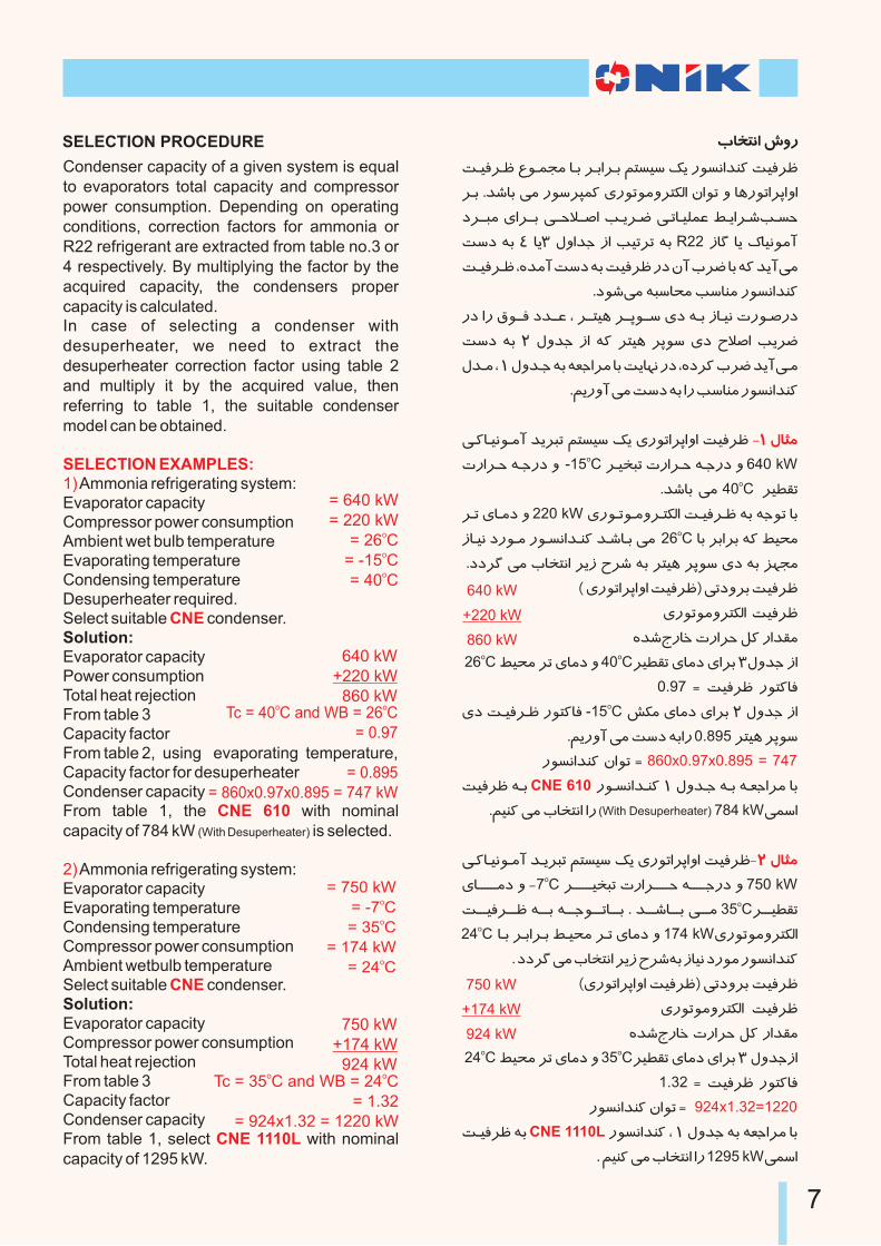
Condenser capacity of a given system is equal to evaporators total capacity and compressor power consumption. Depending on operating conditions, correction factors for ammonia or R22 refrigerant are extracted from table no.3 or 4 respectively. By multiplying the factor by the acquired capacity, the condensers proper capacity is calculated.In case of selecting a condenser with desuperheater, we need to extract the desuperheater correction factor using table 2 and multiply it by the acquired value, then referring to table 1, the suitable condenser model can be obtained.
Ammonia refrigerating system:Evaporator capacityCompressor power consumptionAmbient wet bulb temperatureEvaporating temperatureCondensing temperatureDesuperheater required. Select suitable condenser.Solution:Evaporator capacity Power consumption Total heat rejectionFrom table 3 Capacity factor From table 2, using evaporating temperature, Capacity factor for desuperheater Condenser capacity From table 1, the with nominal capacity of 784 kW (With Desuperheater) is selected.
Ammonia refrigerating system: Evaporator capacity Evaporating temperatureCondensing temperatureCompressor power consumption Ambient wetbulb temperature Select suitable condenser.Solution:Evaporator capacityCompressor power consumption Total heat rejection From table 3Capacity factor Condenser capacityFrom table 1, select with nominal capacity of 1295 kW.
SELECTION EXAMPLES:1)
CNE
CNE 610
2)
CNE
CNE 1110L
= 640 kW= 220 kW
o= 26 Co= -15 Co= 40 C
640 kW+220 kW 860 kW
o oTc = 40 C and WB = 26 C= 0.97
= 0.895= 860x0.97x0.895 = 747 kW
= 750 kWo= -7 Co= 35 C
= 174 kWo= 24 C
750 kW+174 kW 924 kW
o oTc = 35 C and WB = 24 C
= 1.32= 924x1.32 = 1220 kW
SELECTION PROCEDURE
7
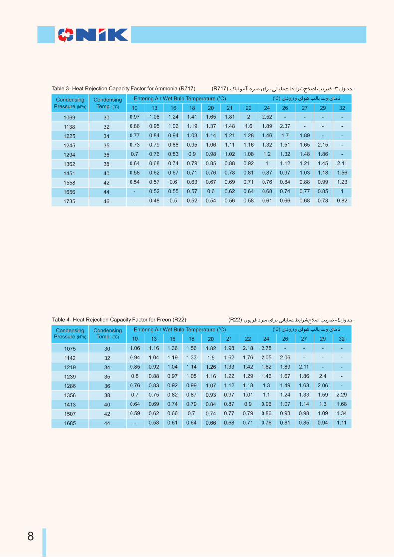
Table 3- Heat Rejection Capacity Factor for Ammonia (R717) (R717) ¥Iú¼¶A joL¶ ÁHoM ÂUIñµø ôÄHo{b°ÅH KÄoò -3 Ï»k]
10
0.97
0.86
0.77
0.73
0.7
0.64
0.58
0.54
-
-
30
32
34
35
36
38
40
42
44
46
1069
1138
1225
1245
1294
1362
1451
1558
1656
1735
13
1.08
0.95
0.84
0.79
0.76
0.68
0.62
0.57
0.52
0.48
16
1.24
1.06
0.94
0.88
0.83
0.74
0.67
0.6
0.55
0.5
18
1.41
1.19
1.03
0.95
0.9
0.79
0.71
0.63
0.57
0.52
20
1.65
1.37
1.14
1.06
0.98
0.85
0.76
0.67
0.6
0.54
21
1.81
1.48
1.21
1.11
1.02
0.88
0.78
0.69
0.62
0.56
22
2
1.6
1.28
1.16
1.08
0.92
0.81
0.71
0.64
0.58
24
2.52
1.89
1.46
1.32
1.2
1
0.87
0.76
0.68
0.61
26
-
2.37
1.7
1.51
1.32
1.12
0.97
0.84
0.74
0.66
27
-
-
1.89
1.65
1.48
1.21
1.03
0.88
0.77
0.68
29
-
-
-
2.15
1.86
1.45
1.18
0.99
0.85
0.73
32
-
-
-
-
-
2.11
1.56
1.23
1
0.82
Condensing
Pressure (kPa)
CondensingoTemp. ( C)
o( C) Áj»n» ÁH¼À K²IM R» ÁI¶joEntering Air Wet Bulb Temperature ( C)
Table 4- Heat Rejection Capacity Factor for Freon (R22) 22) ·¼ÄoÎ joL¶ ÁHoM ÂUIñµø ôÄHo{b°ÅH KÄoò -4Ï»k] (R
10
1.06
0.94
0.85
0.8
0.76
0.7
0.64
0.59
-
30
32
34
35
36
38
40
42
44
1075
1142
1219
1239
1286
1356
1413
1507
1685
13
1.16
1.04
0.92
0.88
0.83
0.75
0.69
0.62
0.58
16
1.36
1.19
1.04
0.97
0.92
0.82
0.74
0.66
0.61
18
1.56
1.33
1.14
1.05
0.99
0.87
0.79
0.7
0.64
20
1.82
1.5
1.26
1.16
1.07
0.93
0.84
0.74
0.66
21
1.98
1.62
1.33
1.22
1.12
0.97
0.87
0.77
0.68
22
2.18
1.76
1.42
1.29
1.18
1.01
0.9
0.79
0.71
24
2.78
2.05
1.62
1.46
1.3
1.1
0.96
0.86
0.76
26
-
2.06
1.89
1.67
1.49
1.24
1.07
0.93
0.81
27
-
-
2.11
1.86
1.63
1.33
1.14
0.98
0.85
29
-
-
-
2.4
2.06
1.59
1.3
1.09
0.94
32
-
-
-
-
-
2.29
1.68
1.34
1.11
Condensing
Pressure (kPa)
CondensingoTemp. ( C)
oEntering Air Wet Bulb Temperature ( C)o
( C) Áj»n» ÁH¼À K²IM R» ÁI¶j
8
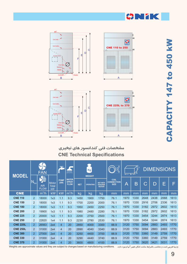
ÁoÃhLU ÁIÀ n¼vºHk¹¨ ¹ΠRI~hz¶
CNE Technical Specifications
CA
PA
CIT
Y 1
47 t
o 4
50 k
W
A
CNE 225L to 370
A
CNE 110 to 250
9
AB
C
MotorTotalkW
Nfan
WEIGHT
COILCONNECTION
SIZEAIR
FLOW
WATERSPRAYFLOW
FANDIMENSIONS
A B C D E F
MODEL
mmkW mmmmmmmmmmmm3
m /h3
m /hkWCNE kg
POMP(kW)
kg kg
NET OPERATINGNET WITHDESUPERHEATER
1450
1700
1950
1980
2200
2230
2850
2890
3250
3290
3600
1900
2200
2450
2480
2750
2780
4000
4040
4400
4440
4800
1750
2000
2250
2280
2500
2530
3300
3340
3700
3740
4100
76.1
76.1
76.1
76.1
76.1
76.1
88.9
88.9
88.9
88.9
88.9
CNE 110
CNE 150
CNE 180
CNE 200
CNE 225
CNE 250
CNE 225L
CNE 250L
CNE 300
CNE 330
CNE 370
1.1
1.1
1.1
1.1
1.1
1.1
4
4
4
4
4
9.3
9.3
9.3
9.3
9.3
9.3
20
20
20
20
20
2
2
2
2
2
2
2
2
2
2
2
18000
18000
18000
19900
20000
22820
26563
31000
27000
31000
31000
1x3
1x3
1x3
1x3
1x3
1x4
2x4
2x4
2x4
2x4
2x4
1970
1970
1970
1970
1970
1970
3120
3120
3120
3120
3120
1330
1330
1330
1330
1330
1330
1750
1750
1750
1750
1750
2648
2916
3182
3182
3454
3454
3094
3094
3360
3360
3620
2438
2706
2972
2972
3244
3244
2883
2883
3149
3149
3421
2068
2336
2602
2602
2874
2874
2493
2493
2759
2759
3031
1613
1613
1613
1613
1613
1613
1770
1770
1770
1770
1770
Weights are approximate values and they are subject to changes based on manufacturing conditions. .jnHj j¼]» I¿ºA oÃÃûU ·I§¶H SiIw ôÄHo{IM KwI¹T¶ » SwH ÂLÄo£U I¿ºp»
Coil Inlet
Coil Outlet
B
3
Makeup
Heater
Over Flow
HeaterOutlet
Access Door
3
F
ED
C
Coil Inlet
Coil Outlet
B
3
Makeup
Heater
Over Flow
HeaterOutlet
Access Door
4
F
ED
C
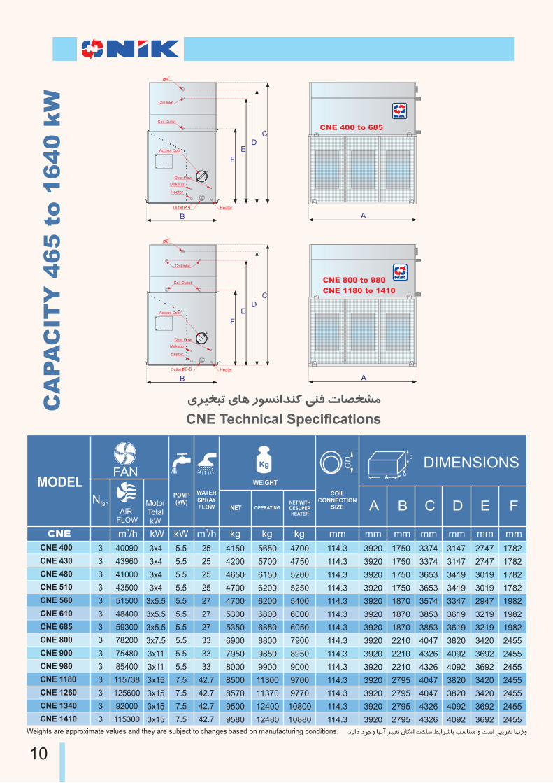
ÁoÃhLU ÁIÀ n¼vºHk¹¨ ¹ΠRI~hz¶
CNE Technical Specifications
A
CNE 400 to 685
A
CNE 800 to 980
CNE 1180 to 1410
CA
PA
CIT
Y 4
65 t
o 1
640 k
W
10
4150
4200
4650
4700
4700
5300
5350
6900
7950
8000
8500
8570
9500
9580
5650
5700
6150
6200
6200
6800
6850
8800
9850
9900
11300
11370
12400
12480
4700
4750
5200
5250
5400
6000
6050
7900
8950
9000
9700
9770
10800
10880
114.3
114.3
114.3
114.3
114.3
114.3
114.3
114.3
114.3
114.3
114.3
114.3
114.3
114.3
CNE 400
CNE 430
CNE 480
CNE 510
CNE 560
CNE 610
CNE 685
CNE 800
CNE 900
CNE 980
CNE 1180
CNE 1260
CNE 1340
CNE 1410
5.5
5.5
5.5
5.5
5.5
5.5
5.5
5.5
5.5
5.5
7.5
7.5
7.5
7.5
25
25
25
25
27
27
27
33
33
33
42.7
42.7
42.7
42.7
3
3
3
3
3
3
3
3
3
3
3
3
3
3
40090
43960
41000
43500
51500
48400
59300
78200
75480
85400
115738
125600
92000
115300
3x4
3x4
3x4
3x4
3x5.5
3x5.5
3x5.5
3x7.5
3x11
3x11
3x15
3x15
3x15
3x15
3920
3920
3920
3920
3920
3920
3920
3920
3920
3920
3920
3920
3920
3920
1750
1750
1750
1750
1870
1870
1870
2210
2210
2210
2795
2795
2795
2795
3374
3374
3653
3653
3574
3853
3853
4047
4326
4326
4047
4047
4326
4326
3147
3147
3419
3419
3347
3619
3619
3820
4092
4092
3820
3820
4092
4092
2747
2747
3019
3019
2947
3219
3219
3420
3692
3692
3420
3420
3692
3692
1782
1782
1782
1782
1982
1982
1982
2455
2455
2455
2455
2455
2455
2455
Weights are approximate values and they are subject to changes based on manufacturing conditions. .jnHj j¼]» I¿ºA oÃÃûU ·I§¶H SiIw ôÄHo{IM KwI¹T¶ » SwH ÂLÄo£U I¿ºp»
AB
C
MotorTotalkW
Nfan
WEIGHT
COILCONNECTION
SIZEAIR
FLOW
WATERSPRAYFLOW
FANDIMENSIONS
A B C D E F
MODEL
mmkW mmmmmmmmmmmm3m /h 3m /hkWCNE kg
POMP(kW)
kg kg
NET OPERATINGNET WITHDESUPERHEATER
Coil Inlet
Coil Outlet
B
6
Makeup
Heater
Over Flow
HeaterOutlet
Access Door
6-8
F
ED
C
Coil Inlet
Coil Outlet
B
4
Makeup
Heater
Over Flow
HeaterOutlet
Access Door
4
F
ED
C
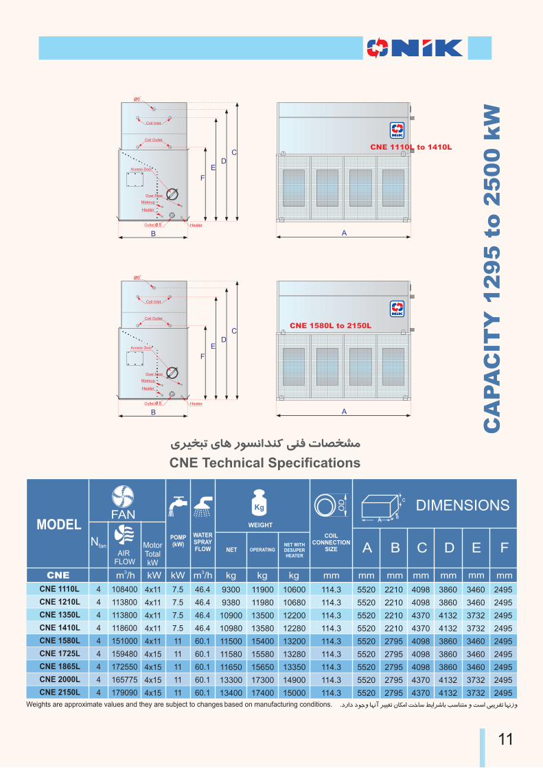
ÁoÃhLU ÁIÀ n¼vºHk¹¨ ¹ΠRI~hz¶
CNE Technical Specifications
CA
PA
CIT
Y 1
295 t
o 2
500 k
W
A
CNE 1580L to 2150L
A
CNE 1110L to 1410L
11
9300
9380
10900
10980
11500
11580
11650
13300
13400
11900
11980
13500
13580
15400
15580
15650
17300
17400
10600
10680
12200
12280
13200
13280
13350
14900
15000
114.3
114.3
114.3
114.3
114.3
114.3
114.3
114.3
114.3
CNE 1110L
CNE 1210L
CNE 1350L
CNE 1410L
CNE 1580L
CNE 1725L
CNE 1865L
CNE 2000L
CNE 2150L
7.5
7.5
7.5
7.5
11
11
11
11
11
46.4
46.4
46.4
46.4
60.1
60.1
60.1
60.1
60.1
4
4
4
4
4
4
4
4
4
108400
113800
113800
118600
151000
159480
172550
165775
179090
4x11
4x11
4x11
4x11
4x11
4x15
4x15
4x15
4x15
5520
5520
5520
5520
5520
5520
5520
5520
5520
2210
2210
2210
2210
2795
2795
2795
2795
2795
4098
4098
4370
4370
4098
4098
4098
4370
4370
3860
3860
4132
4132
3860
3860
3860
4132
4132
3460
3460
3732
3732
3460
3460
3460
3732
3732
2495
2495
2495
2495
2495
2495
2495
2495
2495
Weights are approximate values and they are subject to changes based on manufacturing conditions. .jnHj j¼]» I¿ºA oÃÃûU ·I§¶H SiIw ôÄHo{IM KwI¹T¶ » SwH ÂLÄo£U I¿ºp»
AB
C
MotorTotalkW
Nfan
WEIGHT
COILCONNECTION
SIZEAIR
FLOW
WATERSPRAYFLOW
FANDIMENSIONS
A B C D E F
MODEL
mmkW mmmmmmmmmmmm3m /h 3m /hkWCNE kg
POMP(kW)
kg kg
NET OPERATINGNET WITHDESUPERHEATER
Coil Inlet
Coil Outlet
B
6
Makeup
Heater
Over Flow
HeaterOutlet
Access Door
8
F
ED
C
Coil Inlet
Coil Outlet
B
6
Makeup
Heater
Over Flow
HeaterOutlet
Access Door
8
F
ED
C
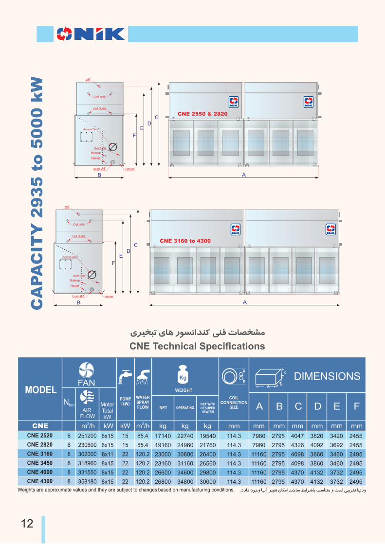
ÁoÃhLU ÁIÀ n¼vºHk¹¨ ¹ΠRI~hz¶
CNE Technical Specifications
A
CNE 3160 to 4300
A
CNE 2550 & 2820
CA
PA
CIT
Y 2
935 t
o 5
000 k
W
12
17140
19160
23000
23160
26600
26800
22740
24960
30800
31160
34600
34800
19540
21760
26400
26560
29800
30000
114.3
114.3
114.3
114.3
114.3
114.3
CNE 2520
CNE 2820
CNE 3160
CNE 3450
CNE 4000
CNE 4300
15
15
22
22
22
22
85.4
85.4
120.2
120.2
120.2
120.2
6
6
8
8
8
8
251200
230600
302000
318960
331550
358180
6x15
6x15
8x11
8x15
8x15
8x15
7960
7960
11160
11160
11160
11160
2795
2795
2795
2795
2795
2795
4047
4326
4098
4098
4370
4370
3820
4092
3860
3860
4132
4132
3420
3692
3460
3460
3732
3732
2455
2455
2495
2495
2495
2495
Weights are approximate values and they are subject to changes based on manufacturing conditions. .jnHj j¼]» I¿ºA oÃÃûU ·I§¶H SiIw ôÄHo{IM KwI¹T¶ » SwH ÂLÄo£U I¿ºp»
AB
C
MotorTotalkW
Nfan
WEIGHT
COILCONNECTION
SIZEAIR
FLOW
WATERSPRAYFLOW
FANDIMENSIONS
A B C D E F
MODEL
mmkW mmmmmmmmmmmm3m /h 3m /hkWCNE kg
POMP(kW)
kg kg
NET OPERATINGNET WITHDESUPERHEATER
Coil Inlet
Coil Outlet
B
6
Makeup
Heater
Over Flow
HeaterOutlet
Access Door
8
F
ED
C
Coil Inlet
Coil Outlet
B
6
Makeup
Heater
Over Flow
HeaterOutlet
Access Door
8
F
ED
C
ELECTRICAL PAN WATER LEVEL CONTROL
A factory–set electrical pan water level control can
be installed on the standard mechanical makeup
valve connection upon customer’s order to
provide exceptionally accurate water level control.
no field adjustment are necessary regardless of
variation in load on the condenser or variation in
makeup water supply pressure. This system
consists of a solenoid valve and an electrical float.
For those types of condensers witch have to work
continuously under water freezing temperature,
using electrical pan water level control is
recommended.
¦TzU JA cõw §ÄoT§²H ÏoT¹¨
Ïo@@T¹¨ ´@@TvÃw , ¦@@TzU JA c@@õw ¢@@äj Ïo@@T¹¨ ÁHo@@M
I@M ¾@¨ S@wH k@¶AnI@¨ nI@ÃvM ÁH ¾@±Ãw» JA cõw §ÄoT§²H
K@@~º Makeup Valve ÏI@@~UH Á»n o@@M Áo@Tz¶ xnI@ÿw
.jnHkº K~º ®d¶ nj ́ ÃʹU ¾M ÁpIú _ÃÀ » j¼{¶
Â@§Äo@T§²H n»I@¹{¦@Ä » Ák@ÃG¼¹²¼w oÃ{ ¦Ä pH ÏoT¹¨ ¸ÄH
ÁI@¶j oÄp kÄIM ¾¨ ÂÄIÀn¼vºHk¹¨ ÁHoM .SwH ½k{®Ã§zU
Â@§Äo@T§²H Ïo@T¹¨ k@ÄI@µº nI¨ ¾Tw¼ÃQ Rn¼Å ¾M JA jIµ\ºH
.j¼{¶ ¾ÃżU » ½j¼M kÃÿ¶ nIÃvM JA cõw
SÃÎoË ÏoT¹¨ ÁIÀ x»n
Â@@ñ÷M nj , S@@wH o@@ÃûT¶ ÏI@w ϼ@önj n¼@vºHk@¹¨ ·H¼@U
JI@hTºH . k@{IM ¶ ®¤Hke ͤH¼¶ Âñ÷M nj » oX¨Hke ͤH¼¶
¾@Îo@Å n¼@ʹ¶ ¾@M ,o@X¨Hk@e Áo@ìnI@M I@M ¢MIõ¶ I¿ÀI«Twj
I@¿¹U S@ÃÎo@Ë Ïo@T¹¨ .k@{I@M Â@¶ ÁroºH ýo~¶ nj Âļ]
j¼@i ®@¤Hk@e nj ´TvÃw ÁoìnIM ¾¨ SwH Án»oò ºI¶p
o@Äp ®@§{¾@M ÁI@Àn¼@vºHk@¹¨ SÃÎoË ÏoT¹¨ ,k{IM
:joì ¶ Rn¼Å
Â@Uj»o@M nI@M ¾@§ÃºI@¶p I@Ä ÂºITv¶p jow nIÃvM ÁH¼À nj-1
JA » k@ù¨ x¼@¶I@iHn JA O@µQ » I@À ¸@Î S@wH ®@¤Hke
( ¦zi RIñµø) . kÃGIµº ¾Ã±hU Hn ¦TzU
I@¿¹Î pH Â@ñ÷M ·H¼@U ¶ ¸ÃGIQ ¾M ôw¼T¶ ÂUj»oM nIM nj-2
ÁHo@@M » ·I@@Äo@Tz¶ ÁI@òI@£U K@ve o@M . jo@¨ x¼@¶I@i Hn
¾@Êÿd¶ ·»nj ¾@M J¼öo¶ ÁH¼À» JA l¼ÿº pH Áoì¼±]
Â@]»o@i ÏI@ºI@¨ Á»n Â@ż@~h¶ oP¶j , x¼¶Ii ÁIÀ ¸Î
.j¼{¶ K~º I¿¹Î
I@À ¸@Î ÁHo@M ¾@Tøo@w»j ÁI@Àn¼@U¼¶»oT§²H pH ·H¼U ¶-3
» ¯I@M S@ÃÎo@Ë ÁHo@M ¯I@M n»j Rn¼Å ¸ÄH nj jo¨ ½jIÿTwH
.j¼{¶ ½joM nI¨ ¾M ̧ ÃGIQ SÃÎoË ÁHoM ̧ ÃGIQ n»j
CNE
Â{jo¬ JA OµQ
Hn ÁoÃhLU ÁIÀn¼vºHk¹¨ ÁoTz¶ xnIÿw oM I¹M
¾@M ½I@«Twj pI@ú I@M K@wI@¹T¶ Â@{jo@¬ JA O@µQ »oT§²H ¾M q¿\¶
.kÄIµº ¶ ¾GHnH ·IÄoTz¶
S¨o{
CIRCULATION POMP
Based on customer request,
delivers evaporative condensers with
proper water circulation electro-pomp.
Company
CNE
CAPACITY CONTROL PROCEDURES
The capacity of refrigerating system varies
during the year and sometimes it is maximum and
some other times is it minimum . Selection of units
is according to maximum load for energy saving.
Capacity control of condensers is done as
follows.
1. In very cold ambient temperature or when the
refrigerating loads is minimum turn off the fans
and pump or only pump and drain the water (dry
operation).
2. In cold ambient temperature or when load is
middle to low turn off some fans. According to
customer request and for prevention of air and
water cross flow from operating fans to idle fans
housing, can supply a type of
metal dampers on fan outlets .
3. Double speed fan motor means that high R.P.M.
is applied for high capacity and low R.P.M. for low
capacity.
CNE
Company
.
.
OPTIONAL EQUIPMENT ÁnIÃTiH RHqÿ\U
13
½nHk¶ k¹a ÁIÀ ®Ä¼¨
¾ºI¬Hk]
ÁI@¿±Ä¼@¨ I@M ÁI@Àn¼@vºHk@¹¨k¹ÄIµº ¶ ®µø
¸@ÃzºI] ¸ÄoT¿M » ½j¼M JIhTºH ¸ÄoU ÁjI~T¤H ½nHk¶ k¹a
¸@@ù`µÀ » ¾@@¹Äq@@Ào@Q » jk@÷T¶ Â@GH¼@À ÁI@Àn¼@vºHk@¹¨
ÁI@À ®@ļ@¨ bo@ö .k¹{IM ¶ N¼ÃU kºH ®{ÁIÀn¼vºHk¹¨
RI@vÃwI@U ̼@º oÀ KwI¹¶ » ½j¼M ̼¹T¶nIÃvM ½nHk¶ k¹a
xnI@@ÿw Hn j¼@@i ½H¼@h²j RI@~hz¶ k@úH¼@U Â@¶ ,S@wH
.kÃÀj
ÁIÀnHk¶ nj n¼woPµ¨k¹a¾¨Â¹Mo¨¼²IÀRIvÃwIU nj
¾ºI¬Hk] CNE
o²¼¨ kÃG¼±Î ®Ä¼¨
½s@Ä» ½I@«ÄI@] Â@¨I@ú¼@¶H RIvÃwIU nj ½nHk¶»j ÁIÀ ®Ä¼¨
» ´@@TvÃw n¼@@vºHk@¹¨ y@£º ·AnHk@¶ ¦@Ä Ho@Äp k@ºnHj ÁH
o@@w y@@ÄI@@¶o@@w ÁHo@M o@²¼@¨ k@ÃG¼@±Î y@£º o@«Äj nHk@¶
¾@M » jnHj ½k@¿ø ¾@MHn IÀn¼woPµ¨ o²¼¨ ®Ä»H » IÀnk¹±Ãw
½I@@«Twj ¦@Ä pH ½nHk@¶ ¦@U ½I@«Twj»j ÁI@\M K@ÃUo@U ¸@ÄH
nj ÁjI@Äp Â@G¼@] ¾@Îo@Å ¾@¨ j¼@{Â@¶ ½jIÿTwH ½nHk¶»j
.jnHj ½HoµÀ ¾M ¾¹ÄqÀ
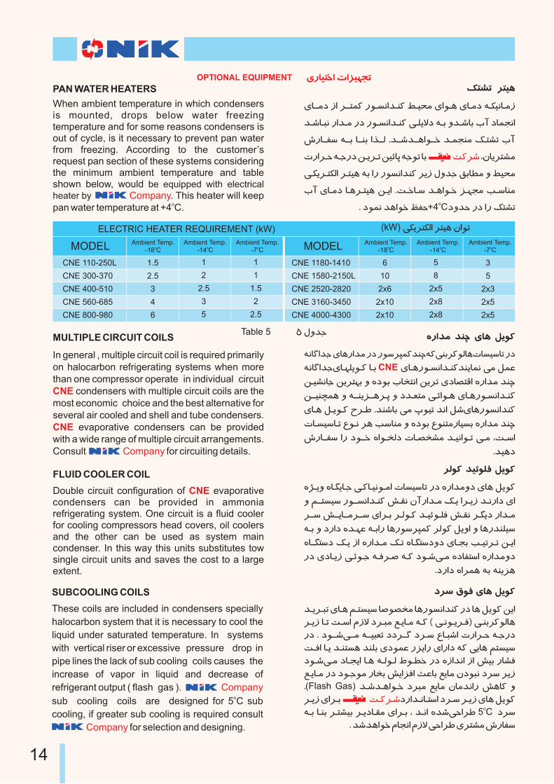
Table 5 5 ϻk]
1
2
2.5
3
5
1.5
2.5
3
4
6
CNE 110-250L
CNE 300-370
CNE 400-510
CNE 560-685
CNE 800-980
1
1
1.5
2
2.5
MODEL Ambient Temp.o
-18 CAmbient Temp.
o-14 C
Ambient Temp.o
-7 C
5
8
2x5
2x8
2x8
6
10
2x6
2x10
2x10
CNE 1180-1410
CNE 1580-2150L
CNE 2520-2820
CNE 3160-3450
CNE 4000-4300
3
5
2x3
2x5
2x5
MODEL Ambient Temp.o
-18 CAmbient Temp.
o-14 C
Ambient Temp.o
-7 C
ELECTRIC HEATER REQUIREMENT (kW) (kW) §ÄoT§²H oTÃÀ ·H¼U
OPTIONAL EQUIPMENT ÁnIÃTiH RHqÿ\U
FLUID COOLER COIL
Double circuit configuration of evaporative condensers can be provided in ammonia refrigerating system. One circuit is a fluid cooler for cooling compressors head covers, oil coolers and the other can be used as system main condenser. In this way this units substitutes tow single circuit units and saves the cost to a large extent.
CNE
SUBCOOLING COILS
These coils are included in condensers specially
halocarbon system that it is necessary to cool the
liquid under saturated temperature. In systems
with vertical riser or excessive pressure drop in
pipe lines the lack of sub cooling coils causes the
increase of vapor in liquid and decrease of
refrigerant output ( flash gas ). osub cooling coils are designed for 5 C sub
cooling, if greater sub cooling is required consult
for selection and designing.
Company
CompanyNIK
MULTIPLE CIRCUIT COILS
In general , multiple circuit coil is required primarily on halocarbon refrigerating systems when more than one compressor operate in individual circuit
condensers with multiple circuit coils are the most economic choice and the best alternative for several air cooled and shell and tube condensers.
evaporative condensers can be provided with a wide range of multiple circuit arrangements. Consult for circuiting details.
CNE
CNE
Company
jow ¡¼Î ÁIÀ ®Ä¼¨
k@Äo@LU ÁI@À ́ @TvÃw ż~h¶ n¼vºHk¹¨ nj IÀ ®Ä¼¨ ̧ ÄH
o@Äp I@U S@wH ³p¯ jo@L¶ Í@ÄI@¶ ¾@¨ ( Â@º¼@Äo@Î) Â@¹Mo¨¼²IÀ
nj . j¼@@{Â@@¶ ¾@@ÃL÷U jjo@@¬ jo@w ÌI@L{H RnHo@e ¾@]nj
S@ÎH I@Ä k@¹TvÀ k¹±M Áj¼µø nqÄHn ÁHnHj ¾¨ ÂÄIÀ ´TvÃw
j¼@{Â@¶ jI@\ÄH I@À ¾@²¼@² ó¼@õi nj ½pHkºH pH yÃM nIzÎ
Í@ÄI@¶ nj j¼@]¼¶ nIhM yÄHqÎH WøIM ÍÄI¶ ·j¼Lº jow oÄp
.(Flash Gas) k@{k@ÀH¼@i joL¶ ÍÄI¶ ·I¶kºHn yÀI¨ »
o@Äp ÁHo@M jnHk@ºI@TwH jo@w o@Äp ÁIÀ ®Ä¼¨o¾@M I@¹M o@TzÃM o@ÄjI@£¶ ÁHo@M , k@ºH ½k{ÂeHoö 5 C jow
. k{kÀH¼i ³I\ºH ³p¯ ÂeHoö ÁoTz¶ xnIÿw
I IÀ
S@¨o@{
PAN WATER HEATERS
When ambient temperature in which condensers is mounted, drops below water freezing temperature and for some reasons condensers is out of cycle, is it necessary to prevent pan water from freezing. According to the customer’s request pan section of these systems considering the minimum ambient temperature and table shown below, would be equipped with electrical heater by . This heater will keep
opan water temperature at +4 C.Company
¦TzU oTÃÀ
ÁI@@¶j pH o@@Tµ¨ n¼@vºHk@¹¨ ô@Ãd¶ ÁH¼@À ÁI@¶j ¾@§ÃºI@¶p
k@{I@Lº nHk@¶ nj n¼@vºHk@¹¨ Â@±Ä¯j ¾@M »k@{IM JA jIµ\ºH
xnI@@ÿw ¾@@M I@@¹M Hm@@² .k@@{k@@ÀH¼@@i k@µ\¹¶ ¦@TzU JA
RnHo@e ¾@]nj ̧ @Äo@U ̧ ÃGIQ ¾]¼U IM ,·IÄoTz¶
Â@§Äo@T§²H o@TÃÀ ¾M Hn n¼vºHk¹¨ oÄp Ï»k] ¢MIõ¶ » ôÃd¶
JA ÁI@¶j I@Ào@TÃÀ ¸@ÄH .S@iI@w k@ÀH¼@i q@¿\¶ K@wI¹¶o . j¼µº kÀH¼i Éÿe+4 Cj»ke nj Hn ¦TzU
S¨o{
14
K~º x»n
¾@M ÁIÀn¼vºHk¹¨ , K~º » ®£º» ®µe S²¼¿w ÁHoM
nj , k@º¼@{Â@¶ ¾@TiI@w( ®@ļ@¨ » ¦@TzU) ¾@anIQ »j boö
nHo@¤ Ro@QI@w ÁIÀoÃU Á»n Hn ¦TzU HkTMH K~º ·I¶p
·A Á¯I@M ́ @Äo@Î Á»n ¦@ú Ák@¹M JA nH¼º ÁH ¾Ä¯ » ́ ÃÀjÂ@¶
, ´@@ÃGI@@µº Â@@¶ K@~º Hn ®@ļ@¨ u@Pw » , ´@ù¨ Â@¶ K@~º
Án»o@ò ®@v§M ÁI@À ®@MI@¨ » ³Hn , ®@ãYo] ·j¼M KwI¹¶
.SwH
CNE
RoQIw ÁIÀoÃU
¾@÷õ¤ »j ÁI@Àn¼@vºHk@¹¨ pI@ú jn¼¶ RoQIw ÁIÀoÃU
jnHj jHk@T¶H ½I«Twj ϼö ³IµU nj ¾¨ k{IM ¶ I ¸ÀA oÃU
·¼@ÃvºHk@º¼@Î I@Ä Áq@±Î nHo@£TwH Á¼@§w Á»n k@ºH¼@U ¶»
½k@¿÷M ¼@§w » ·¼ÃvºHkº¼Î IÄ IÀoÃU ¸ÄH ¾Ã¿U j¼{¾T{Hm¬
Â@¬k@õi pI@\¶ ·Hq@ö » I@À ¸ÀAoÃU ¾±ÅIÎ SwH ÁoTz¶
.k{IM ¶ Ï»k] ¢Lö I¿ºA
Â@UI@ñµø ·p» k@Å nj ½I@\¹Q »k@Å k@ÄIM IÀoÃU ¾LwId¶ nj
¢@@äj k@ÄIM ½I«Twj pHo@U .j¼@{¾@TÎo@¬ o@ʺ nj ½I@«Twj
.SwH 1.5 mm/m pI\¶ ÁpHoU Iº oX¨Hke »k{IM
CNE
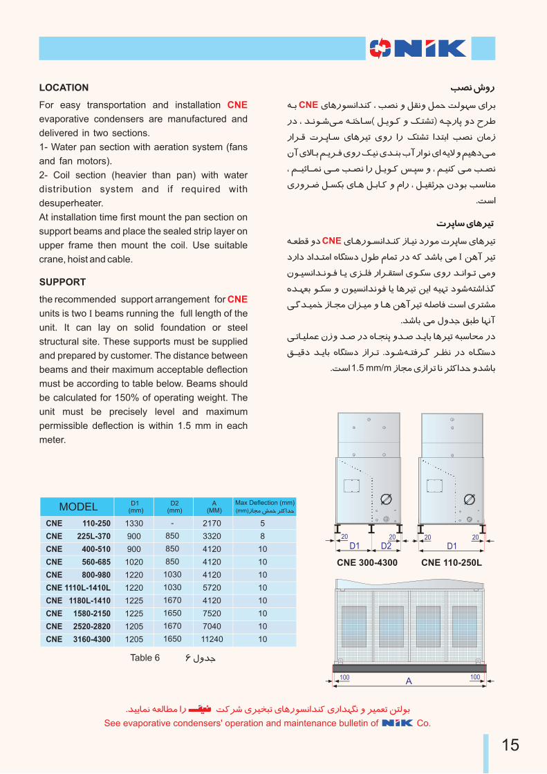
Table 6 6 ϻk]
-
850
850
850
1030
1030
1670
1650
1670
1650
1330
900
900
1020
1220
1220
1225
1225
1205
1205
110-250
225L-370
400-510
560-685
800-980
1110L-1410L
1180L-1410
1580-2150
2520-2820
3160-4300
2170
3320
4120
4120
4120
5720
4120
7520
7040
11240
MODEL D1 (mm)
D2(mm)
A(MM)
5
8
10
10
10
10
10
10
10
10
Max Deflection (mm)(mm)pI\¶ yµi oX¨Hke
LOCATION
For easy transportation and installation
evaporative condensers are manufactured and
delivered in two sections.
1- Water pan section with aeration system (fans
and fan motors).
2- Coil section (heavier than pan) with water
distribution system and if required with
desuperheater.
At installation time first mount the pan section on
support beams and place the sealed strip layer on
upper frame then mount the coil. Use suitable
crane, hoist and cable.
CNE
.
.
.
SUPPORT
the recommended support arrangement for
units is two I beams running the full length of the
unit. It can lay on solid foundation or steel
structural site. These supports must be supplied
and prepared by customer. The distance between
beams and their maximum acceptable deflection
must be according to table below. Beams should
be calculated for 150% of operating weight. The
unit must be precisely level and maximum
permissible deflection is within 1.5 mm in each
meter.
CNE
.kÃÄIµº ¾÷²Iõ¶ Hn S¨o{ ÁoÃhLU ÁIÀn¼vºHk¹¨ ÁnHk¿«º » oõ÷U ¸T²¼M
See evaporative condensers' operation and maintenance bulletin of Co.
15
CNE
CNE
CNE
CNE
CNE
CNE
CNE
CNE
CNE
CNE
CNE 110-250LCNE 300-4300
A100 100
D120 20
D1 D220 20
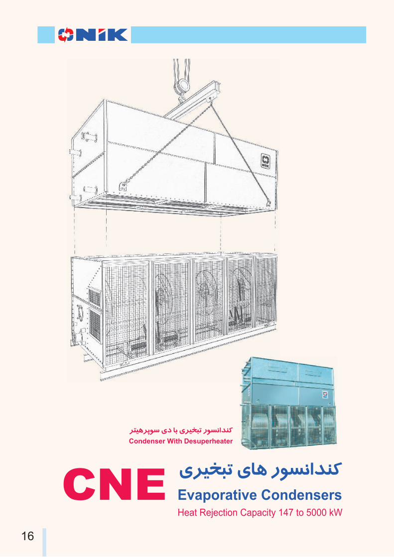
CNEHeat Rejection Capacity 147 to 5000 kW
ÁoÃhLU ÁIÀ n¼vºHk¹¨
Evaporative Condensers
oTÃÀoQ¼w Áj IM ÁoÃhLU n¼vºHk¹¨
Condenser With Desuperheater
16

o@LT÷¶ ÁI@À jnHk@ºI@TwH S@ÄI@øn I@M S@¨o@{¸@ÄH RHk@ò¼@U
IIR, BS, AD-Merkblattero@@@@@@@@@Ãʺ Â@@@@@@@@@±±µ²H¸@@@@@@@@ÃM
» ·Ho@ÄH µñ¤H ôÄHo{IM ¢Lõ¹¶ » ARI, ANSI/ASHREA,
,Â@TºHnI@¬ R°@ÿvU ÁHnHj » jjo@¬ Â@¶ ¾òoø ¯IM SÃÿè IM
.k{IM ¶ ¨kÄ RI÷õ¤ ¸Ã¶IU » x»oÎ pH uQ RI¶ki
ÂUnHoe » ÂUj»oM S¨o{Ákò¼U R¯¼~d¶Our company's products are presented complying
with international valid standards like ARI,
ANSI/ASHREA, IIR, BS, AD-Merkblatter, with high
quality according to Iran climate. They provide such
a good facilities like warranty, after sale services and
spare part supply. .
pH Á»o@ÃQ I@M ½nH¼@µÀ
S@Ãÿè EI@£UnH » É@ÿe nj Â@÷w S@Ãÿè j¼@L¿M Â@z¶ ô@i
¾@@M ¢@@μ@@¶ » S@@wH ¾@T{Hj j¼@i R¯¼@~d¶ » RHk@ò¼@U
.SwH ½kÄjo¬ ÂÄIQ»nH jnHkºITwH SÎIÄnj
» Jo@\¶ ·I@wI@¹{nI¨ » SÃÿè ÏoT¹¨ keH» pH Áoì ½o¿M
Áo@@ì ½pHk@@ºH ÁI@@À ½I@«Twj » RI@ºI@§¶H ¾@M ·j¼@M q@¿\¶
¸@§µ¶ ®@¤Hk@e ¾@M Hn ½I@LT{H » I@õi p»o@M ÏIµTeH ,¾TÎozÃQ
.kºIwn¶
RnI@ʺ I@M kò¼U þ±Th¶ ®eHo¶ nj SÃÿè ÏoT¹¨ ·IwnpIM
k@@ò¼@@U ®@@¹wo@@Q I@M o@§ÿµÀ » ½Ho@µÀ ,j¼@i Â@¹Î » Â@µ±ø
o@T¿M ÁI@À nI@§ÀHn ¹ΠjnH¼¶ ÏoT¹¨ oM ½»°ø IU k¹{¼¨Â¶
Ïo@T¹¨ ¾@¹Ã¶p nj ¾@a » k@ò¼U ¾¹Ã¶p nj ¾a Hn ÁoU kÄk] »
.k¹Àj ¾GHnH
¾@M jnHk@ºI@TwH JI@hTºH I@M
·I@¶pI@w k@ÃÄI@U I@M S@Ãÿè S@Äo@Äk@¶ ´@TvÃw Á¼«²H ·H¼¹ø
¢@£dU ÁHo@M ³p¯ o@TvM jI\ÄH » ½k¹Àj ÂÀH¼¬
EI@£UnH nj j¼@i ®@¹wo@Q ³IµU ÁIÀ ÂÄIºH¼U pH oµTv¶ j¼L¿M
S@@Ãÿè » ½jo@@M ½o@@¿M Áo@@Tz¶ S@ÄI@òn » S@Ãÿè c@õw
.kÄIµº ¶ ¸ÃµñU Hn j¼i R¯¼~d¶
Â@UnHo@e » Â@Uj»oM S¨o{
S@¨o{ISO 9001:2000
SÃÿè j¼L¿M Âz¶ ôi
B&H Company
Company
has been always following
Quality Improvement Policy, and trying to maintain
and promotes its products' quality and has been
succeeded to obtain the european standard .
Utilization of Quality Control Department and
qualified experts equipped with facilities and
advanced measuring devices minimize the
probability of error.
Quality Control Inspectors try to offer better and
newer applicable solution both in production and
control processes. In addition, to controlling the
technical problems in different stages of
manufacturing through exertion of scientific and
technical inspection along with other personnel.
has made provisions for
realization of continual improvement by choosing
standard.
It makes use of all personnel to promote quality
level and customer satisfaction, in this way it
guarantees products' quality.
.
. ISO 9001:2000
17
Head office:
Factory:
No. 163, Kheradmand shomali ave.
Tehran 15859, IRAN
Tel: +98 21 88840745 , 88840731 , 88826073
Fax: +98 21 88838188
No 10 , 63rd Ave, Karaj Makhsoos Rd
17th km, Tehran, Iran
Tel: +98 21 44986332, +98 21 44986359
Fax: +98 21 44980237 www.nikbhco.com
163 ½nIµ{,²Iµ{k¹¶joi ·IMIÃi ,·Ho¿U
15875/3965 ÂTvQ ¡»k¹Å ,¦Ãº ·IµTiIw
88838188 :u§Î ,88840731, 88826073 :¸ÿ±U
17 oT¶¼±Ã¨ ,Zo¨ |¼~h¶ ½jI] ,·Ho¿U
33561 ÂTvQk¨ ,10 ½nIµ{,63 ·IMIÃi
44980237 :u§Î ,44986332, 44986359 :¸ÿ±U
:Áq¨o¶ oTÎj
:¾ºIinI¨