Embed Size (px)
Citation preview
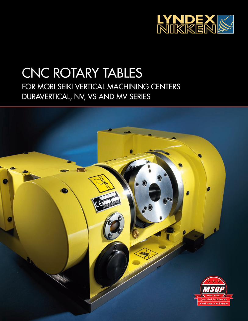
CNC ROTARY TABLESFOR MORI SEIKI VERTICAL MACHINING CENTERSDURAVERTICAL, NV, VS AND MV SERIES
Faceplate Ø Part Number
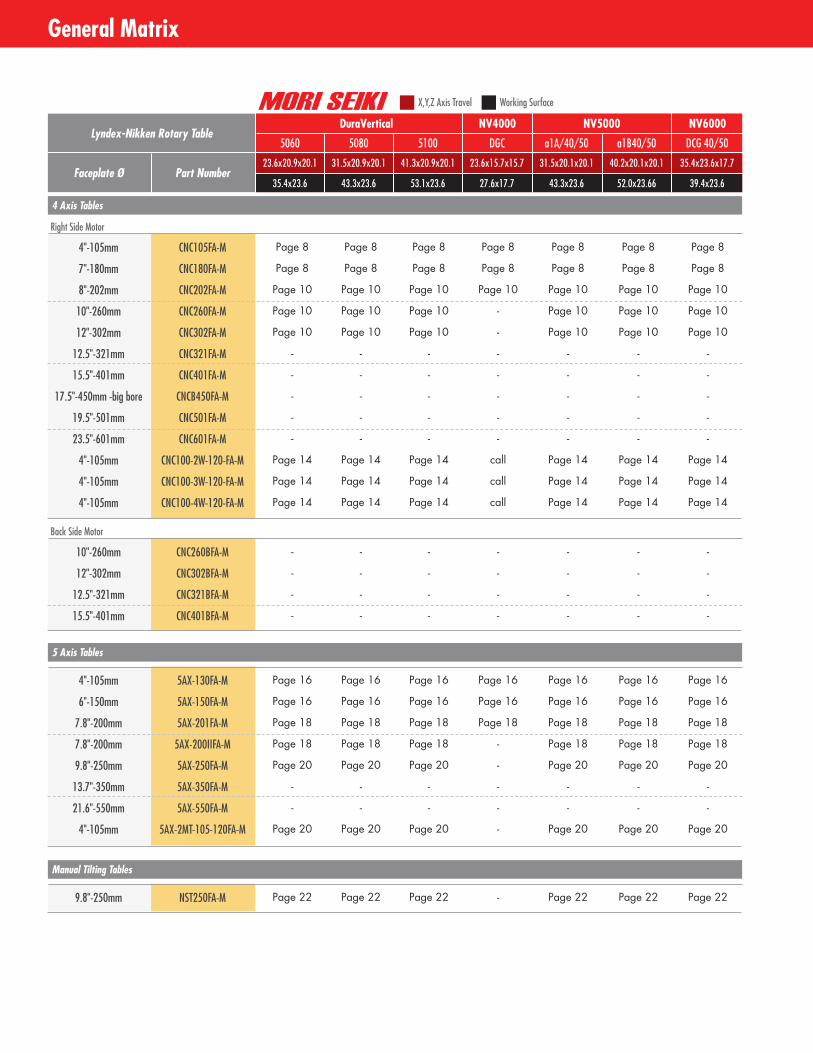
Lyndex-Nikken Rotary TableDuraVertical
5060 5080 5100
23.6x20.9x20.1 31.5x20.9x20.1 41.3x20.9x20.1
35.4x23.6 43.3x23.6 53.1x23.6
NV4000
DGC
23.6x15.7x15.7
27.6x17.7
NV5000
a1A/40/50 a1B40/50
31.5x20.1x20.1 40.2x20.1x20.1
43.3x23.6 52.0x23.66
NV6000
DCG 40/50
35.4x23.6x17.7
39.4x23.6
Page 8 Page 8 Page 8 Page 8 Page 8 Page 8 Page 8
Page 8 Page 8 Page 8 Page 8 Page 8 Page 8 Page 8
Page 10 Page 10 Page 10 Page 10 Page 10 Page 10 Page 10
Page 10 Page 10 Page 10 - Page 10 Page 10 Page 10
Page 10 Page 10 Page 10 - Page 10 Page 10 Page 10
- - - - - - -
- - - - - - -
- - - - - - -
- - - - - - -
- - - - - - -
Page 14 Page 14 Page 14 call Page 14 Page 14 Page 14
Page 14 Page 14 Page 14 call Page 14 Page 14 Page 14
Page 14 Page 14 Page 14 call Page 14 Page 14 Page 14
4"-105mm CNC105FA-M
7"-180mm CNC180FA-M
8"-202mm CNC202FA-M
10"-260mm CNC260FA-M
12"-302mm CNC302FA-M
12.5"-321mm CNC321FA-M
15.5"-401mm CNC401FA-M
17.5"-450mm -big bore CNCB450FA-M
19.5"-501mm CNC501FA-M
23.5"-601mm CNC601FA-M
4"-105mm CNC100-2W-120-FA-M
4"-105mm CNC100-3W-120-FA-M
4"-105mm CNC100-4W-120-FA-M
X,Y,Z Axis Travel Working Surface
4 Axis Tables
Right Side Motor
- - - - - - -
- - - - - - -
- - - - - - -
- - - - - - -
10"-260mm CNC260BFA-M
12"-302mm CNC302BFA-M
12.5"-321mm CNC321BFA-M
15.5"-401mm CNC401BFA-M
Back Side Motor
Page 16 Page 16 Page 16 Page 16 Page 16 Page 16 Page 16
Page 16 Page 16 Page 16 Page 16 Page 16 Page 16 Page 16
Page 18 Page 18 Page 18 Page 18 Page 18 Page 18 Page 18
Page 18 Page 18 Page 18 - Page 18 Page 18 Page 18
Page 20 Page 20 Page 20 - Page 20 Page 20 Page 20
- - - - - - -
- - - - - - -
Page 20 Page 20 Page 20 - Page 20 Page 20 Page 20
4"-105mm 5AX-130FA-M
6"-150mm 5AX-150FA-M
7.8"-200mm 5AX-201FA-M
7.8"-200mm 5AX-200IIFA-M
9.8"-250mm 5AX-250FA-M
13.7"-350mm 5AX-350FA-M
21.6"-550mm 5AX-550FA-M
4"-105mm 5AX-2MT-105-120FA-M
5 Axis Tables
Page 22 Page 22 Page 22 - Page 22 Page 22 Page 229.8"-250mm NST250FA-M
Manual Tilting Tables
General Matrix
General Matrix
1
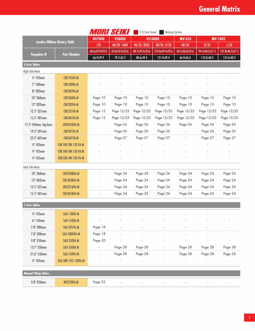
Faceplate Ø Part Number
Lyndex-Nikken Rotary TableNV7000
/50 40/50 -1600 40/50 -2050
60.6x29.9x29.0 63.0x33.9x23.6 80.7x39.4x23.6
66.9x29.9 78.7x33.5 88.6x39.4
VS10000
40/50 -3150
124.0x39.4x23.6
131.9x39.4
MV-653
40/50 B/50
60.2x26.0x25.6 94.5x40.2x31.5
66.9x26.0 110.2x40.2
MV-1003
L/50
137.8x40.2x31.5
153.5x40.2
- - - - - - -
- - - - - - -
- - - - - - -
Page 10 Page 10 Page 10 Page 10 Page 10 Page 10 Page 10
Page 10 Page 10 Page 10 Page 10 Page 10 Page 10 Page 10
Page 12 Page 12/25 Page 12/25 Page 12/25 Page 12/25 Page 12/25 Page 12/25
Page 12 Page 12/25 Page 12/25 Page 12/25 Page 12/25 Page 12/25 Page 12/25
Page 26 Page 26 Page 26 Page 26 Page 26 Page 26
Page 26 Page 26 Page 26 - Page 26 Page 26
Page 27 Page 27 Page 27 - Page 27 Page 27
- - - - - - -
- - - - - - -
- - - - - - -
4"-105mm CNC105FA-M
7"-180mm CNC180FA-M
8"-202mm CNC202FA-M
10"-260mm CNC260FA-M
12"-302mm CNC302FA-M
12.5"-321mm CNC321FA-M
15.5"-401mm CNC401FA-M
17.5"-450mm -big bore CNCB450FA-M
19.5"-501mm CNC501FA-M
23.5"-601mm CNC601FA-M
4"-105mm CNC100-2W-120-FA-M
4"-105mm CNC100-3W-120-FA-M
4"-105mm CNC100-4W-120-FA-M
X,Y,Z Axis Travel Working Surface
4 Axis Tables
Right Side Motor
- Page 24 Page 24 Page 24 Page 24 Page 24 Page 24
- Page 24 Page 24 Page 24 Page 24 Page 24 Page 24
- Page 24 Page 24 Page 24 Page 24 Page 24 Page 24
- Page 24 Page 24 Page 24 Page 24 Page 24 Page 24
10"-260mm CNC260BFA-M
12"-302mm CNC302BFA-M
12.5"-321mm CNC321BFA-M
15.5"-401mm CNC401BFA-M
Back Side Motor
- - - - - - -
- - - - - - -
Page 18 - - - - - -
Page 18 - - - - - -
Page 20 - - - - - -
- Page 28 Page 28 - Page 28 Page 28 Page 28
- Page 28 Page 28 - Page 28 Page 28 Page 28
- - - - - - -
4"-105mm 5AX-130FA-M
6"-150mm 5AX-150FA-M
7.8"-200mm 5AX-201FA-M
7.8"-200mm 5AX-200IIFA-M
9.8"-250mm 5AX-250FA-M
13.7"-350mm 5AX-350FA-M
21.6"-550mm 5AX-550FA-M
4"-105mm 5AX-2MT-105-120FA-M
5 Axis Tables
Page 22 - - - - - -9.8"-250mm NST250FA-M
Manual Tilting Tables
VS8000
2
General Matrix
Table of Contents
Introduction
Features and Technology
Product Specifications and Application Drawings
Rotary Tables for Mori Seiki DuraVertical and NV Series
4 Axis Rotary Tables
5 Axis Rotary Tables
Manual Tilting Rotary Tables
Rotary Tables for Mori Seiki VS and MV Series
4 Axis Rotary Tables
5 Axis Rotary Tables
Accessories
Installation and Interface
Service and Repair
Static and Live Tools
Inside cover - 1
2
3
4 - 7
8 - 28
8 - 23
8 - 15
16- 21
22 - 23
24 - 28
24 - 27
28
29
30 - 31
32
Inside back cover
The world’s number one most durable, precise and rigid CNC Rotary Tablesare provided from these assembly lines to the worldwide market.
Table of Contents
3
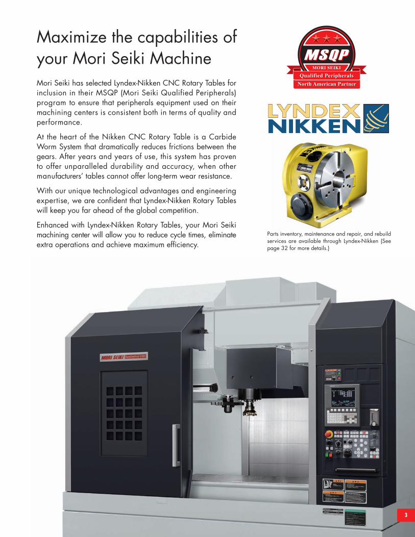
Mori Seiki has selected Lyndex-Nikken CNC Rotary Tables forinclusion in their MSQP (Mori Seiki Qualified Peripherals)program to ensure that peripherals equipment used on theirmachining centers is consistent both in terms of quality andperformance.
At the heart of the Nikken CNC Rotary Table is a CarbideWorm System that dramatically reduces frictions between thegears. After years and years of use, this system has provento offer unparalleled durability and accuracy, when othermanufacturers’ tables cannot offer long-term wear resistance.
With our unique technological advantages and engineeringexpertise, we are confident that Lyndex-Nikken Rotary Tableswill keep you far ahead of the global competition.
Enhanced with Lyndex-Nikken Rotary Tables, your Mori Seikimachining center will allow you to reduce cycle times, eliminateextra operations and achieve maximum efficiency.
Maximize the capabilities ofyour Mori Seiki Machine
Parts inventory, maintenance and repair, and rebuildservices are available through Lyndex-Nikken (Seepage 32 for more details.)
4
Features and Technology
Nikken’s complete line of CNC Rotary Tables is recognized worldwide for wear-resistance,rigidity and high-speed rotation. Every part of every table is designed and built to providehigh accuracy, increased production and a trouble-free long life. All Nikken RotaryTables have built-in features and benefits unmatched by the competition.
Casting and SealingThe environments in which CNC rotary tables are used are becoming increasingly severe with each passing year.Nikken Rotary Tables utilize fine grain high-density Gray Cast Iron castings. These castings offer long-term stability,low distortion and high strength. Casting is roughed out and a period of 30 days is allowed for the casting tostabilize before the rotary table is finished being machined.
Now that cutting fluids are used in large quantities, waterproofing of CNC rotary tables has become veryimportant. When used for a long period of time, the table bearing race in particular becomes a problem.That’s why the bearing race of Nikken Rotary Tables consists of hardened steel (HRC58-60) polished to a mirrorfinish. The edge of the rotary table is sealed by a special seal ring that prevents cutting fluid from entering theunit, even when used for a long period of time.
Assessment and InspectionOur tables are thoroughly assessed thru various series of testssuch as overload test, rigidity test, cutting stability test, andbrake torque test. Every table is 100% inspected andcomes with an inspection certificate.
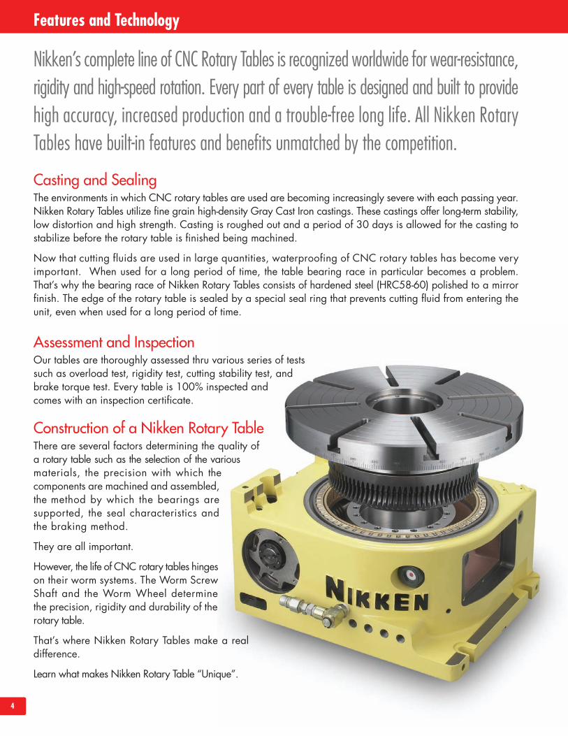
Construction of a Nikken Rotary TableThere are several factors determining the quality ofa rotary table such as the selection of the variousmaterials, the precision with which thecomponents are machined and assembled,the method by which the bearings aresupported, the seal characteristics andthe braking method.
They are all important.
However, the life of CNC rotary tables hingeson their worm systems. The Worm ScrewShaft and the Worm Wheel determinethe precision, rigidity and durability of therotary table.
That’s where Nikken Rotary Tables make a realdifference.
Learn what makes Nikken Rotary Table “Unique”.
5
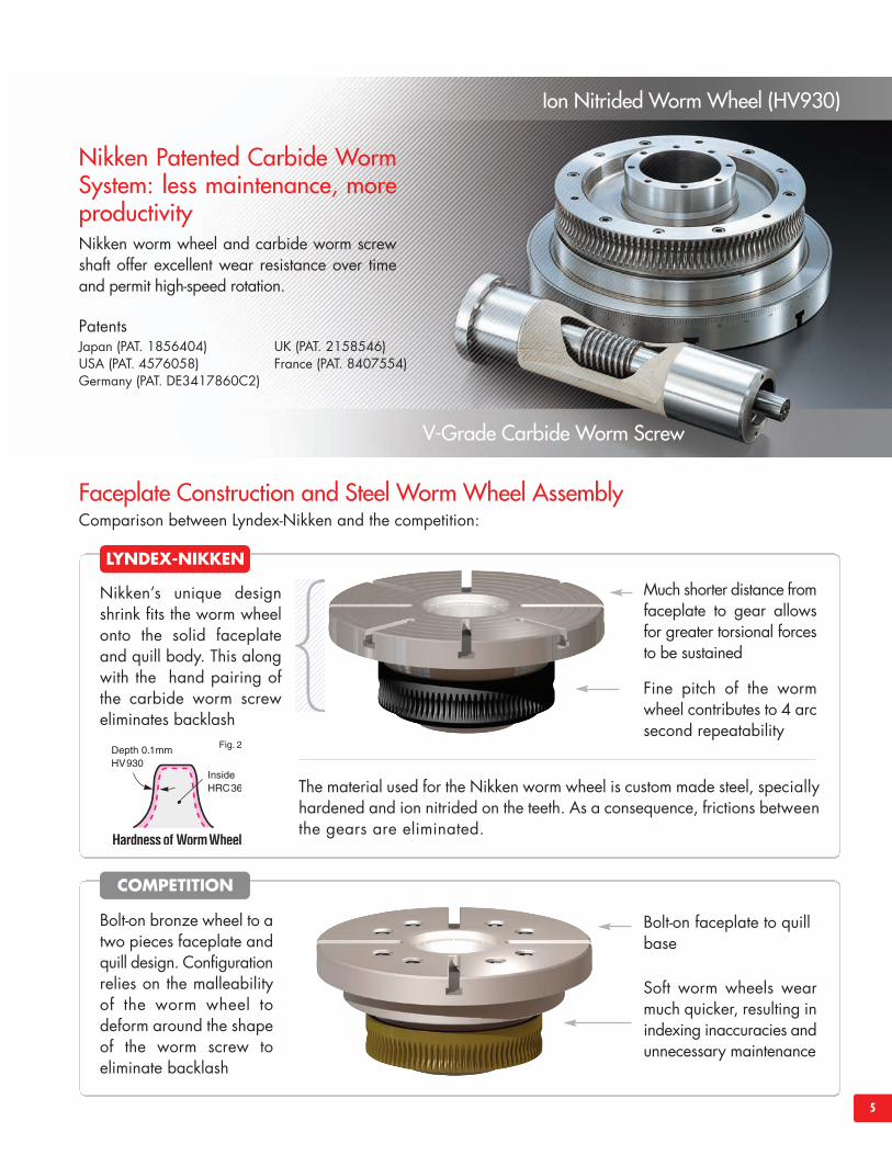
Faceplate Construction and Steel Worm Wheel AssemblyComparison between Lyndex-Nikken and the competition:
Nikken’s unique designshrink fits the worm wheelonto the solid faceplateand quill body. This alongwith the hand pairing ofthe carbide worm screweliminates backlash
Much shorter distance fromfaceplate to gear allowsfor greater torsional forcesto be sustained
Fine pitch of the wormwheel contributes to 4 arcsecond repeatability
The material used for the Nikken worm wheel is custom made steel, speciallyhardened and ion nitrided on the teeth. As a consequence, frictions betweenthe gears are eliminated.
Bolt-on bronze wheel to atwo pieces faceplate andquill design. Configurationrelies on the malleabilityof the worm wheel todeform around the shapeof the worm screw toeliminate backlash
Bolt-on faceplate to quillbase
Soft worm wheels wearmuch quicker, resulting inindexing inaccuracies andunnecessary maintenance
Ion Nitrided Worm Wheel (HV930)
V-Grade Carbide Worm Screw
Nikken Patented Carbide WormSystem: less maintenance, moreproductivityNikken worm wheel and carbide worm screwshaft offer excellent wear resistance over timeand permit high-speed rotation.
COMPETITION
LYNDEX-NIKKEN
PatentsJapan (PAT. 1856404)USA (PAT. 4576058)Germany (PAT. DE3417860C2)
UK (PAT. 2158546)France (PAT. 8407554)
6
Features and Technology
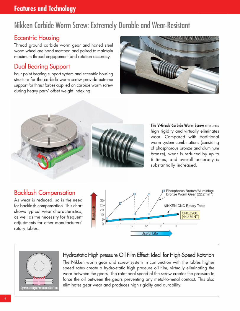
Nikken Carbide Worm Screw: Extremely Durable and Wear-Resistant
Dual Bearing SupportFour point bearing support system and eccentric housingstructure for the carbide worm screw provide extremesupport for thrust forces applied on carbide worm screwduring heavy part/ offset weight indexing.
The V-Grade Carbide Worm Screw ensureshigh rigidity and virtually eliminateswear. Compared with traditionalworm system combinations (consistingof phosphorous bronze and aluminumbronze), wear is reduced by up to8 times, and overall accuracy issubstantially increased.
Backlash CompensationAs wear is reduced, so is the needfor backlash compensation. This chartshows typical wear characteristics,as well as the necessity for frequentadjustments for other manufacturers’rotary tables.
Hydrostatic High pressure Oil Film Effect: Ideal for High-Speed RotationThe Nikken worm gear and screw system in conjunction with the tables higherspeed rates create a hydro-static high pressure oil film, virtually eliminating thewear between the gears. The rotational speed of the screw creates the pressure toforce the oil between the gears preventing any metal-to-metal contact. This alsoeliminates gear wear and produces high rigidity and durability.
Eccentric HousingThread ground carbide worm gear and honed steelworm wheel are hand matched and paired to maintainmaximum thread engagement and rotation accuracy.
7
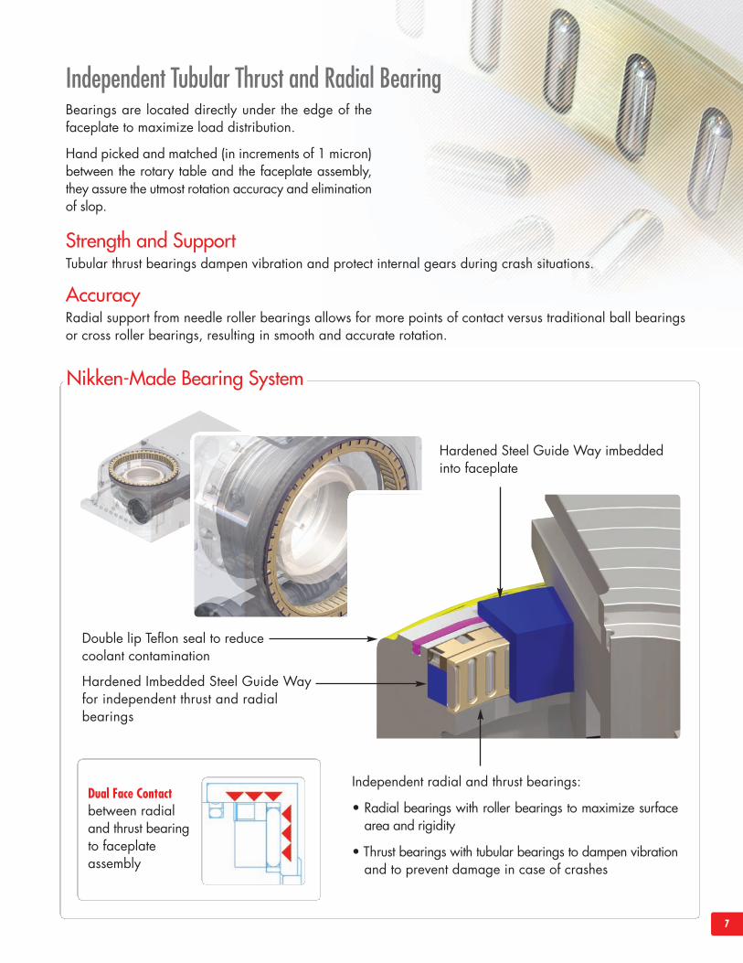
Bearings are located directly under the edge of thefaceplate to maximize load distribution.
Hand picked and matched (in increments of 1 micron)between the rotary table and the faceplate assembly,they assure the utmost rotation accuracy and eliminationof slop.
Strength and SupportTubular thrust bearings dampen vibration and protect internal gears during crash situations.
Nikken-Made Bearing System
Hardened Steel Guide Way imbeddedinto faceplate
Double lip Teflon seal to reducecoolant contamination
Hardened Imbedded Steel Guide Wayfor independent thrust and radialbearings
Independent radial and thrust bearings:
• Radial bearings with roller bearings to maximize surfacearea and rigidity
• Thrust bearings with tubular bearings to dampen vibrationand to prevent damage in case of crashes
Independent Tubular Thrust and Radial Bearing
AccuracyRadial support from needle roller bearings allows for more points of contact versus traditional ball bearingsor cross roller bearings, resulting in smooth and accurate rotation.
Dual Face Contactbetween radialand thrust bearingto faceplateassembly
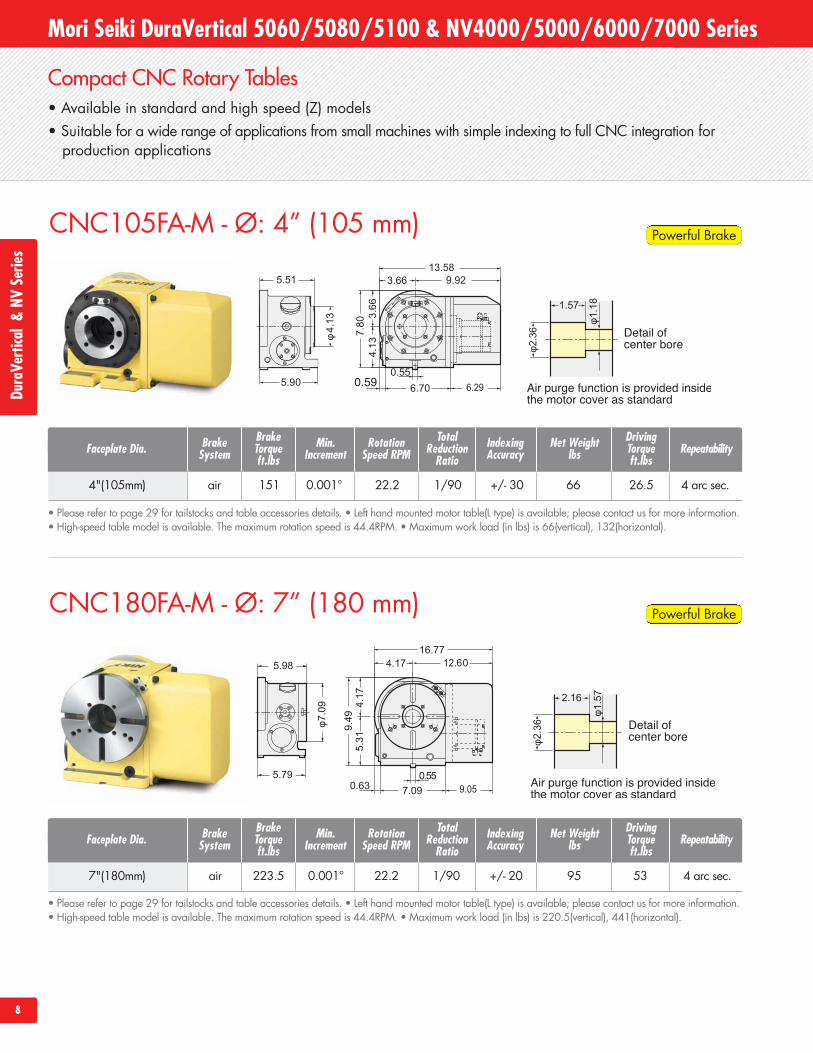
CNC105FA-M - Ø: 4” (105 mm)
• Available in standard and high speed (Z) models• Suitable for a wide range of applications from small machines with simple indexing to full CNC integration for
production applications
8
Compact CNC Rotary Tables
4"(105mm) air 151 0.001° 22.2 1/90 +/- 30 66 26.5 4 arc sec.
Faceplate Dia.BrakeTorqueft.lbs
TotalReductionRatio
Net Weightlbs
IndexingAccuracy Repeatability
DrivingTorqueft.lbs
CNC180FA-M - Ø: 7” (180 mm)
• Please refer to page 29 for tailstocks and table accessories details. • Left hand mounted motor table(L type) is available; please contact us for more information.• High-speed table model is available. The maximum rotation speed is 44.4RPM. • Maximum work load (in lbs) is 66(vertical), 132(horizontal).
RotationSpeed RPM
BrakeSystem
Min.Increment
• Please refer to page 29 for tailstocks and table accessories details. • Left hand mounted motor table(L type) is available; please contact us for more information.• High-speed table model is available. The maximum rotation speed is 44.4RPM. • Maximum work load (in lbs) is 220.5(vertical), 441(horizontal).
Mori Seiki DuraVertical 5060/5080/5100 & NV4000/5000/6000/7000 SeriesDu
raVe
rtical&NV
Serie
s
7"(180mm) air 223.5 0.001° 22.2 1/90 +/- 20 95 53 4 arc sec.
Faceplate Dia.BrakeTorqueft.lbs
TotalReductionRatio
Net Weightlbs
IndexingAccuracy Repeatability
DrivingTorqueft.lbs
RotationSpeed RPM
BrakeSystem
Min.Increment
Powerful Brake
Powerful Brake
9
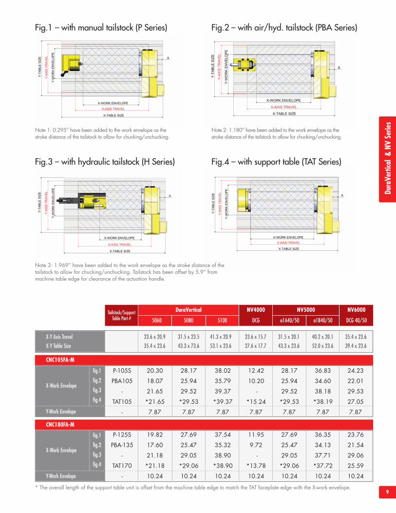
Fig.1 – with manual tailstock (P Series) Fig.2 – with air/hyd. tailstock (PBA Series)
Fig.3 – with hydraulic tailstock (H Series) Fig.4 – with support table (TAT Series)
DuraVe
rtical&NV
Serie
s
X-Y Axis Travel
X-Y Table Size
23.6 x 20.9
35.4 x 23.6
31.5 x 23.5
43.3 x 73.6
41.3 x 20.9
53.1 x 23.6
23.6 x 15.7
27.6 x 17.7
31.5 x 20.1
43.3 x 23.6
40.2 x 20.1
52.0 x 23.6
35.4 x 23.6
39.4 x 23.6
fig.1
fig.2
fig.3
fig.4
X-Work Envelope
Y-Work Envelope
fig.1
fig.2
fig.3
fig.4
X-Work Envelope
Y-Work Envelope
CNC180FA-M
DuraVertical NV4000 NV5000 NV6000
DCG a1A40/50 a1B40/50 DCG 40/505060 5080 5100
CNC105FA-M
Tailstock/SupportTable Part #
P-105S 20.30 28.17 38.02 12.42 28.17 36.83 24.23
PBA105 18.07 25.94 35.79 10.20 25.94 34.60 22.01
- 21.65 29.52 39.37 - 29.52 38.18 29.53
TAT105 *21.65 *29.53 *39.37 *15.24 *29.53 *38.19 27.05
- 7.87 7.87 7.87 7.87 7.87 7.87 7.87
P-125S 19.82 27.69 37.54 11.95 27.69 36.35 23.76
PBA-135 17.60 25.47 35.32 9.72 25.47 34.13 21.54
- 21.18 29.05 38.90 - 29.05 37.71 29.06
TAT170 *21.18 *29.06 *38.90 *13.78 *29.06 *37.72 25.59
- 10.24 10.24 10.24 10.24 10.24 10.24 10.24
Note 1: 0.295” have been added to the work envelope as thestroke distance of the tailstock to allow for chucking/unchucking.
Note 2: 1.180” have been added to the work envelope as thestroke distance of the tailstock to allow for chucking/unchucking.
Note 3: 1.969” have been added to the work envelope as the stroke distance of thetailstock to allow for chucking/unchucking. Tailstock has been offset by 5.9” frommachine table edge for clearance of the actuation handle.
* The overall length of the support table unit is offset from the machine table edge to match the TAT faceplate edge with the X-work envelope.
• Available in standard and high speed (Z) models• Several options available for motor mounting position, including right side, back and top• Highest weight load capacity in its class
Standard CNC Rotary Tables
10
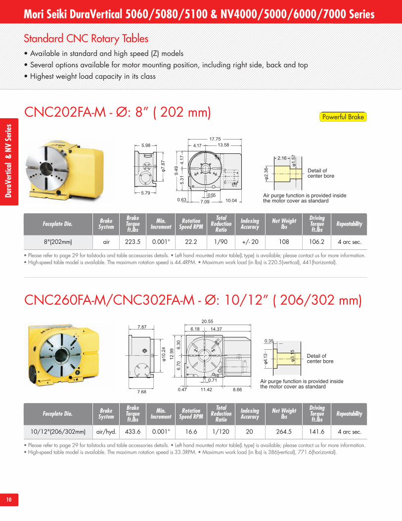
CNC202FA-M - Ø: 8” ( 202 mm)
CNC260FA-M/CNC302FA-M - Ø: 10/12” ( 206/302 mm)
Mori Seiki DuraVertical 5060/5080/5100 & NV4000/5000/6000/7000 SeriesDu
raVe
rtical&NV
Serie
s
• Please refer to page 29 for tailstocks and table accessories details. • Left hand mounted motor table(L type) is available; please contact us for more information.• High-speed table model is available. The maximum rotation speed is 44.4RPM. • Maximum work load (in lbs) is 220.5(vertical), 441(horizontal).
8"(202mm) air 223.5 0.001° 22.2 1/90 +/- 20 108 106.2 4 arc sec.
Faceplate Dia.BrakeTorqueft.lbs
TotalReductionRatio
Net Weightlbs
IndexingAccuracy Repeatability
DrivingTorqueft.lbs
RotationSpeed RPM
BrakeSystem
Min.Increment
• Please refer to page 29 for tailstocks and table accessories details. • Left hand mounted motor table(L type) is available; please contact us for more information.• High-speed table model is available. The maximum rotation speed is 33.3RPM. • Maximum work load (in lbs) is 386(vertical), 771.6(horizontal).
10/12"(206/302mm) air/hyd. 433.6 0.001° 16.6 1/120 20 264.5 141.6 4 arc sec.
Faceplate Dia.BrakeTorqueft.lbs
TotalReductionRatio
Net Weightlbs
IndexingAccuracy Repeatability
DrivingTorqueft.lbs
RotationSpeed RPM
BrakeSystem
Min.Increment
Powerful Brake
11
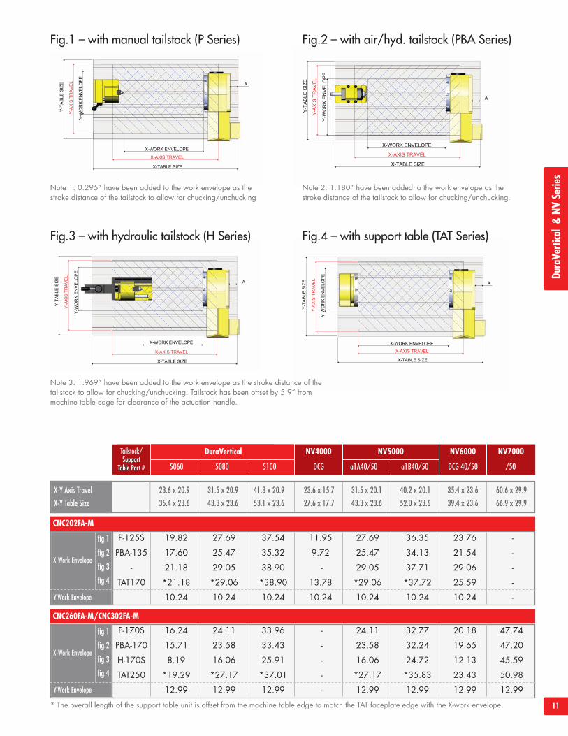
Fig.1 – with manual tailstock (P Series) Fig.2 – with air/hyd. tailstock (PBA Series)
Fig.3 – with hydraulic tailstock (H Series) Fig.4 – with support table (TAT Series)
X-Y Axis Travel
X-Y Table Size
23.6 x 20.9
35.4 x 23.6
31.5 x 20.9
43.3 x 23.6
41.3 x 20.9
53.1 x 23.6
23.6 x 15.7
27.6 x 17.7
31.5 x 20.1
43.3 x 23.6
40.2 x 20.1
52.0 x 23.6
35.4 x 23.6
39.4 x 23.6
60.6 x 29.9
66.9 x 29.9
fig.1
fig.2
fig.3
fig.4
X-Work Envelope
Y-Work Envelope
fig.1
fig.2
fig.3
fig.4
X-Work Envelope
Y-Work Envelope
CNC260FA-M/CNC302FA-M
DuraVertical NV4000 NV5000 NV6000 NV7000
DCG a1A40/50 a1B40/50 DCG 40/50 /505060 5080 5100
CNC202FA-M
Tailstock/Support
Table Part #
P-125S 19.82 27.69 37.54 11.95 27.69 36.35 23.76 -
PBA-135 17.60 25.47 35.32 9.72 25.47 34.13 21.54 -
- 21.18 29.05 38.90 - 29.05 37.71 29.06 -
TAT170 *21.18 *29.06 *38.90 13.78 *29.06 *37.72 25.59 -
10.24 10.24 10.24 10.24 10.24 10.24 10.24 -
P-170S 16.24 24.11 33.96 - 24.11 32.77 20.18 47.74
PBA-170 15.71 23.58 33.43 - 23.58 32.24 19.65 47.20
H-170S 8.19 16.06 25.91 - 16.06 24.72 12.13 45.59
TAT250 *19.29 *27.17 *37.01 - *27.17 *35.83 23.43 50.98
12.99 12.99 12.99 - 12.99 12.99 12.99 12.99
Note 1: 0.295” have been added to the work envelope as thestroke distance of the tailstock to allow for chucking/unchucking
Note 2: 1.180” have been added to the work envelope as thestroke distance of the tailstock to allow for chucking/unchucking.
Note 3: 1.969” have been added to the work envelope as the stroke distance of thetailstock to allow for chucking/unchucking. Tailstock has been offset by 5.9” frommachine table edge for clearance of the actuation handle.
* The overall length of the support table unit is offset from the machine table edge to match the TAT faceplate edge with the X-work envelope.
DuraVe
rtical&NV
Serie
s
• Available in standard and high speed (Z) models• Several options available for motor mounting position, including right side, back and top.
Standard CNC Rotary Tables – Heavy Duty Machining
12
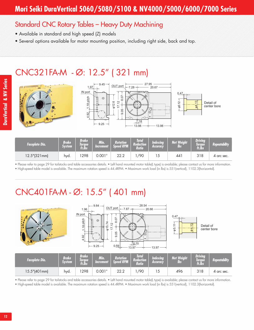
CNC321FA-M - Ø: 12.5” ( 321 mm)
CNC401FA-M - Ø: 15.5” ( 401 mm)
Mori Seiki DuraVertical 5060/5080/5100 & NV4000/5000/6000/7000 SeriesDu
raVe
rtical&NV
Serie
s
• Please refer to page 29 for tailstocks and table accessories details. • Left hand mounted motor table(L type) is available; please contact us for more information.• High-speed table model is available. The maximum rotation speed is 44.4RPM. • Maximum work load (in lbs) is 551(vertical), 1102.3(horizontal).
12.5"(321mm) hyd. 1298 0.001° 22.2 1/90 15 441 318 4 arc sec.
Faceplate Dia.BrakeTorqueft.lbs
TotalReductionRatio
Net Weightlbs
IndexingAccuracy Repeatability
DrivingTorqueft.lbs
RotationSpeed RPM
BrakeSystem
Min.Increment
• Please refer to page 29 for tailstocks and table accessories details. • Left hand mounted motor table(L type) is available; please contact us for more information.• High-speed table model is available. The maximum rotation speed is 44.4RPM. • Maximum work load (in lbs) is 551(vertical), 1102.3(horizontal).
15.5"(401mm) hyd. 1298 0.001° 22.2 1/90 15 496 318 4 arc sec.
Faceplate Dia.BrakeTorqueft.lbs
TotalReductionRatio
Net Weightlbs
IndexingAccuracy Repeatability
DrivingTorqueft.lbs
RotationSpeed RPM
BrakeSystem
Min.Increment
13
X-Y Axis Travel
X-Y Table Size
fig.1
fig.2
fig.3X-Work Envelope
Y-Work Envelope
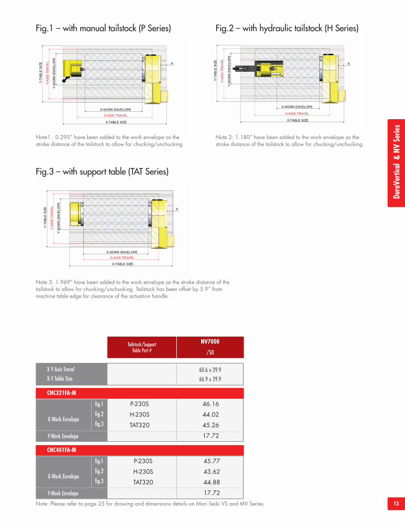
NV7000
/50
CNC321FA-M
Tailstock/SupportTable Part #
P-230S 46.16
H-230S 44.02
TAT320 45.26
17.72
60.6 x 29.9
66.9 x 29.9
fig.1
fig.2
fig.3X-Work Envelope
Y-Work Envelope
CNC401FA-M
P-230S 45.77
H-230S 43.62
TAT320 44.88
17.72
Fig.1 – with manual tailstock (P Series) Fig.2 – with hydraulic tailstock (H Series)
Fig.3 – with support table (TAT Series)
Note1 : 0.295” have been added to the work envelope as thestroke distance of the tailstock to allow for chucking/unchucking
Note 2: 1.180” have been added to the work envelope as thestroke distance of the tailstock to allow for chucking/unchucking.
Note 3: 1.969” have been added to the work envelope as the stroke distance of thetailstock to allow for chucking/unchucking. Tailstock has been offset by 5.9” frommachine table edge for clearance of the actuation handle.
DuraVe
rtical&NV
Serie
s
Note: Please refer to page 25 for drawing and dimensions details on Mori Seiki VS and MV Series.
14
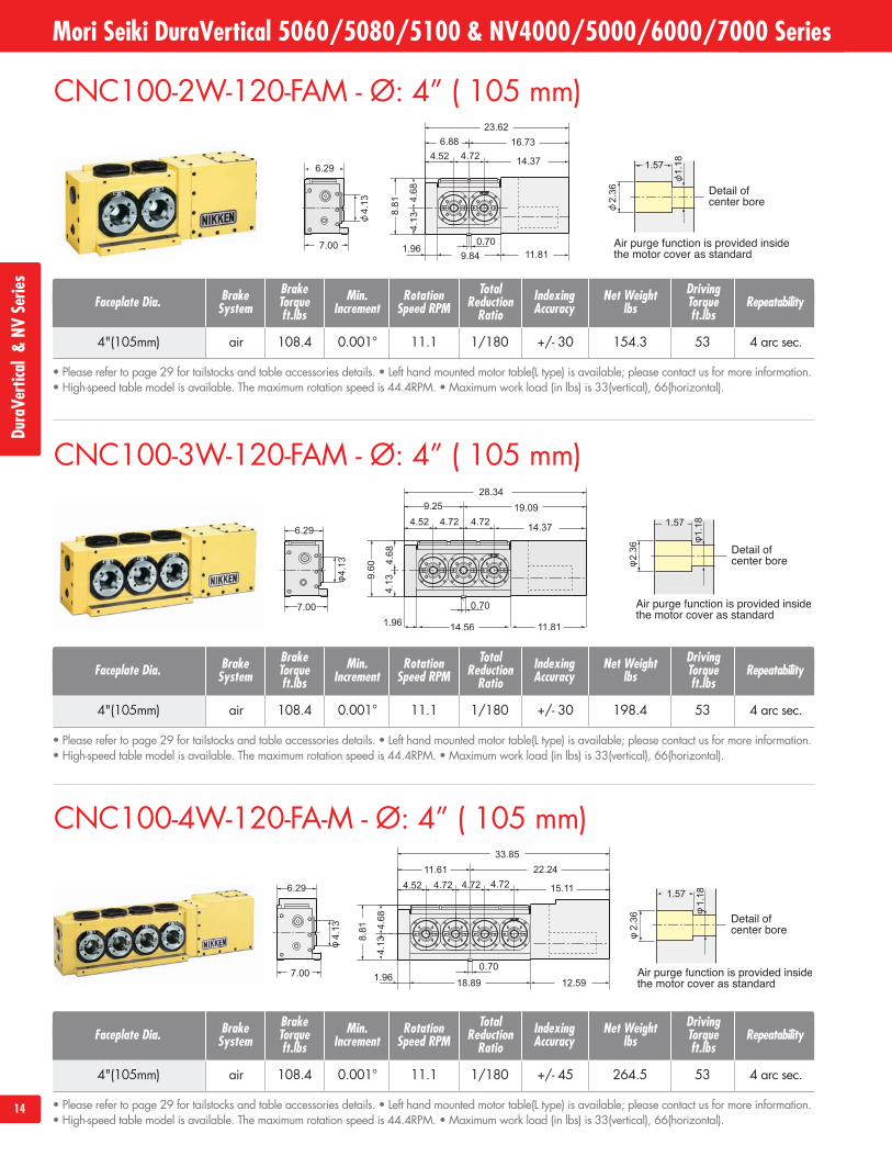
CNC100-3W-120-FAM - Ø: 4” ( 105 mm)
CNC100-4W-120-FA-M - Ø: 4” ( 105 mm)
Mori Seiki DuraVertical 5060/5080/5100 & NV4000/5000/6000/7000 SeriesDu
raVe
rtical&NV
Serie
s
CNC100-2W-120-FAM - Ø: 4” ( 105 mm)
• Please refer to page 29 for tailstocks and table accessories details. • Left hand mounted motor table(L type) is available; please contact us for more information.• High-speed table model is available. The maximum rotation speed is 44.4RPM. • Maximum work load (in lbs) is 33(vertical), 66(horizontal).
4"(105mm) air 108.4 0.001° 11.1 1/180 +/- 30 154.3 53 4 arc sec.
Faceplate Dia.BrakeTorqueft.lbs
TotalReductionRatio
Net Weightlbs
IndexingAccuracy Repeatability
DrivingTorqueft.lbs
RotationSpeed RPM
BrakeSystem
Min.Increment
• Please refer to page 29 for tailstocks and table accessories details. • Left hand mounted motor table(L type) is available; please contact us for more information.• High-speed table model is available. The maximum rotation speed is 44.4RPM. • Maximum work load (in lbs) is 33(vertical), 66(horizontal).
4"(105mm) air 108.4 0.001° 11.1 1/180 +/- 30 198.4 53 4 arc sec.
Faceplate Dia.BrakeTorqueft.lbs
TotalReductionRatio
Net Weightlbs
IndexingAccuracy Repeatability
DrivingTorqueft.lbs
RotationSpeed RPM
BrakeSystem
Min.Increment
• Please refer to page 29 for tailstocks and table accessories details. • Left hand mounted motor table(L type) is available; please contact us for more information.• High-speed table model is available. The maximum rotation speed is 44.4RPM. • Maximum work load (in lbs) is 33(vertical), 66(horizontal).
4"(105mm) air 108.4 0.001° 11.1 1/180 +/- 45 264.5 53 4 arc sec.
Faceplate Dia.BrakeTorqueft.lbs
TotalReductionRatio
Net Weightlbs
IndexingAccuracy Repeatability
DrivingTorqueft.lbs
RotationSpeed RPM
BrakeSystem
Min.Increment
15
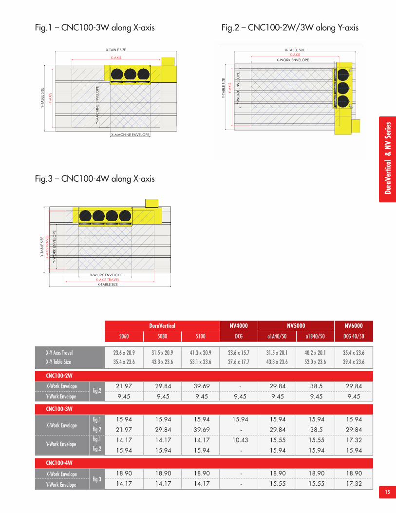
Fig.1 – CNC100-3W along X-axis Fig.2 – CNC100-2W/3W along Y-axis
Fig.3 – CNC100-4W along X-axis
X-Y Axis Travel
X-Y Table Size
23.6 x 20.9
35.4 x 23.6
31.5 x 20.9
43.3 x 23.6
41.3 x 20.9
53.1 x 23.6
23.6 x 15.7
27.6 x 17.7
31.5 x 20.1
43.3 x 23.6
40.2 x 20.1
52.0 x 23.6
35.4 x 23.6
39.4 x 23.6
fig.2X-Work Envelope
Y-Work Envelope
DuraVertical NV4000 NV5000 NV6000
DCG a1A40/50 a1B40/50 DCG 40/505060 5080 5100
CNC100-2W
21.97 29.84 39.69 - 29.84 38.5 29.84
9.45 9.45 9.45 9.45 9.45 9.45 9.45
fig.3X-Work Envelope
Y-Work Envelope
CNC100-4W
18.90 18.90 18.90 - 18.90 18.90 18.90
14.17 14.17 14.17 - 15.55 15.55 17.32
DuraVe
rtical&NV
Serie
s
fig.1
fig.2
fig.1
fig.2
X-Work Envelope
Y-Work Envelope
CNC100-3W
15.94 15.94 15.94 15.94 15.94 15.94 15.94
21.97 29.84 39.69 - 29.84 38.5 29.84
14.17 14.17 14.17 10.43 15.55 15.55 17.32
15.94 15.94 15.94 - 15.94 15.94 15.94
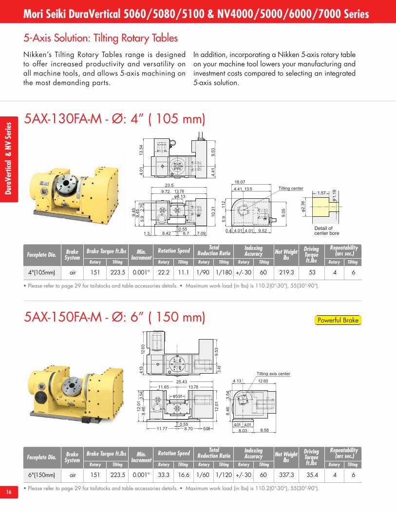
5AX-150FA-M - Ø: 6” ( 150 mm)
5AX-130FA-M - Ø: 4” ( 105 mm)
5-Axis Solution: Tilting Rotary TablesNikken’s Tilting Rotary Tables range is designedto offer increased productivity and versatility onall machine tools, and allows 5-axis machining onthe most demanding parts.
In addition, incorporating a Nikken 5-axis rotary tableon your machine tool lowers your manufacturing andinvestment costs compared to selecting an integrated5-axis solution.
16
• Please refer to page 29 for tailstocks and table accessories details. • Maximum work load (in lbs) is 110.2(0°-30°), 55(30°-90°).
Mori Seiki DuraVertical 5060/5080/5100 & NV4000/5000/6000/7000 SeriesDu
raVe
rtical&NV
Serie
s
4"(105mm) air 151 223.5 0.001° 22.2 11.1 1/90 1/180 +/- 30 60 219.3 53 4 6
Faceplate Dia. Brake Torque ft.lbsTotal
Reduction Ratio Net Weightlbs
IndexingAccuracy
Repeatability(arc sec.)
DrivingTorqueft.lbs
Rotation SpeedBrakeSystem
Min.Increment
Rotary Tilting Rotary Tilting Rotary TiltingRotary Tilting Rotary Tilting
• Please refer to page 29 for tailstocks and table accessories details. • Maximum work load (in lbs) is 110.2(0°-30°), 55(30°-90°).
6"(150mm) air 151 223.5 0.001° 33.3 16.6 1/60 1/120 +/- 30 60 337.3 35.4 4 6
Faceplate Dia. Brake Torque ft.lbsTotal
Reduction Ratio Net Weightlbs
IndexingAccuracy
Repeatability(arc sec.)
DrivingTorqueft.lbs
Rotation SpeedBrakeSystem
Min.Increment
Rotary Tilting Rotary Tilting Rotary TiltingRotary Tilting Rotary Tilting
Powerful Brake
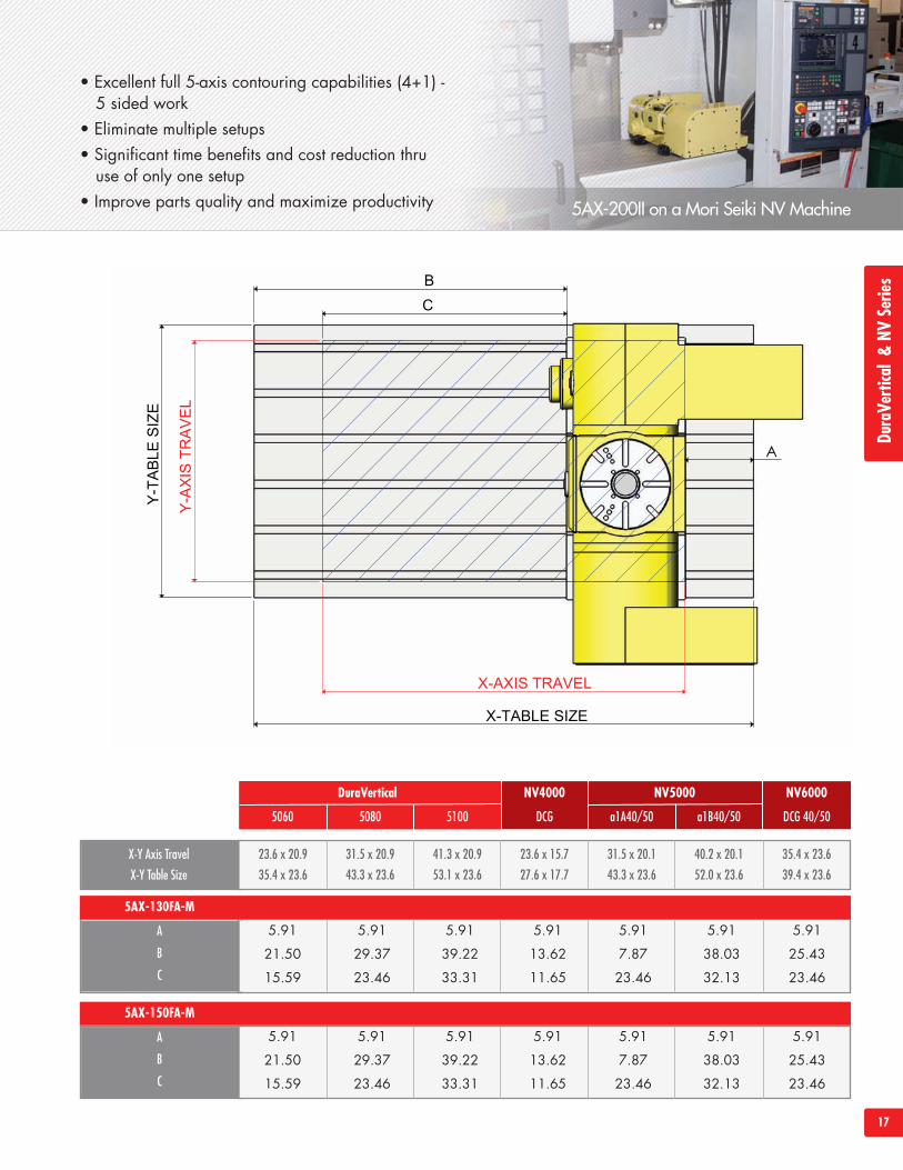
• Excellent full 5-axis contouring capabilities (4+1) -5 sided work
• Eliminate multiple setups• Significant time benefits and cost reduction thru
use of only one setup• Improve parts quality and maximize productivity 5AX-200II on a Mori Seiki NV Machine
17
X-Y Axis Travel
X-Y Table Size
23.6 x 20.9
35.4 x 23.6
31.5 x 20.9
43.3 x 23.6
41.3 x 20.9
53.1 x 23.6
23.6 x 15.7
27.6 x 17.7
31.5 x 20.1
43.3 x 23.6
40.2 x 20.1
52.0 x 23.6
35.4 x 23.6
39.4 x 23.6
A
B
C
DuraVertical NV4000 NV5000 NV6000
DCG a1A40/50 a1B40/50 DCG 40/505060 5080 5100
5AX-130FA-M
5.91 5.91 5.91 5.91 5.91 5.91 5.91
21.50 29.37 39.22 13.62 7.87 38.03 25.43
15.59 23.46 33.31 11.65 23.46 32.13 23.46
A
B
C
5AX-150FA-M
5.91 5.91 5.91 5.91 5.91 5.91 5.91
21.50 29.37 39.22 13.62 7.87 38.03 25.43
15.59 23.46 33.31 11.65 23.46 32.13 23.46
DuraVe
rtical&NV
Serie
s
18
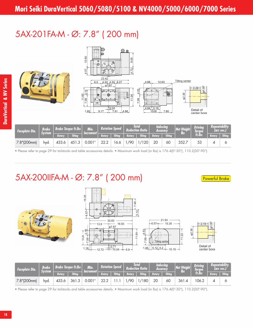
5AX-200IIFA-M - Ø: 7.8” ( 200 mm)
5AX-201FA-M - Ø: 7.8” ( 200 mm)
Mori Seiki DuraVertical 5060/5080/5100 & NV4000/5000/6000/7000 SeriesDu
raVe
rtical&NV
Serie
s
• Please refer to page 29 for tailstocks and table accessories details. • Maximum work load (in lbs) is 176.4(0°-30°), 110.2(30°-90°).
7.8"(200mm) hyd. 433.6 451.3 0.001° 22.2 16.6 1/90 1/120 20 60 352.7 53 4 6
Faceplate Dia. Brake Torque ft.lbsTotal
Reduction Ratio Net Weightlbs
IndexingAccuracy
Repeatability(arc sec.)
DrivingTorqueft.lbs
Rotation SpeedBrakeSystem
Min.Increment
Rotary Tilting Rotary Tilting Rotary TiltingRotary Tilting Rotary Tilting
• Please refer to page 29 for tailstocks and table accessories details. • Maximum work load (in lbs) is 176.4(0°-30°), 110.2(30°-90°).
7.8"(200mm) hyd. 433.6 361.3 0.001° 22.2 11.1 1/90 1/180 20 60 361.4 106.2 4 6
Faceplate Dia. Brake Torque ft.lbsTotal
Reduction Ratio Net Weightlbs
IndexingAccuracy
Repeatability(arc sec.)
DrivingTorqueft.lbs
Rotation SpeedBrakeSystem
Min.Increment
Rotary Tilting Rotary Tilting Rotary TiltingRotary Tilting Rotary Tilting
Powerful Brake
19
X-Y Axis Travel
X-Y Table Size
23.6 x 20.9
35.4 x 23.6
31.5 x 20.9
43.3 x 23.6
41.3 x 20.9
53.1 x 23.6
23.6 x 15.7
27.6 x 17.7
31.5 x 20.1
43.3 x 23.6
40.2 x 20.1
52.0 x 23.6
35.4 x 23.6
39.4 x 23.6
60.6 x 29.9
66.9 x 29.9
A
B
C
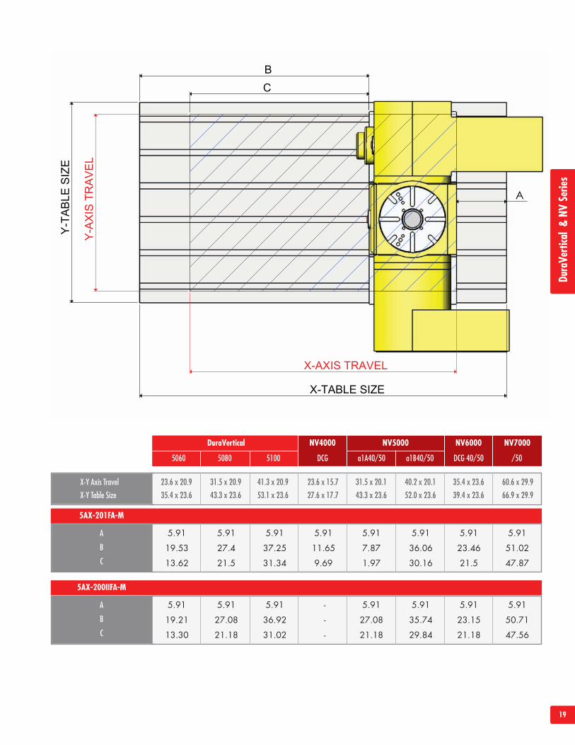
DuraVertical NV4000 NV5000 NV6000 NV7000
DCG a1A40/50 a1B40/50 DCG 40/50 /505060 5080 5100
5AX-201FA-M
5.91 5.91 5.91 5.91 5.91 5.91 5.91 5.91
19.53 27.4 37.25 11.65 7.87 36.06 23.46 51.02
13.62 21.5 31.34 9.69 1.97 30.16 21.5 47.87
A
B
C
5AX-200IIFA-M
5.91 5.91 5.91 - 5.91 5.91 5.91 5.91
19.21 27.08 36.92 - 27.08 35.74 23.15 50.71
13.30 21.18 31.02 - 21.18 29.84 21.18 47.56
DuraVe
rtical&NV
Serie
s
20
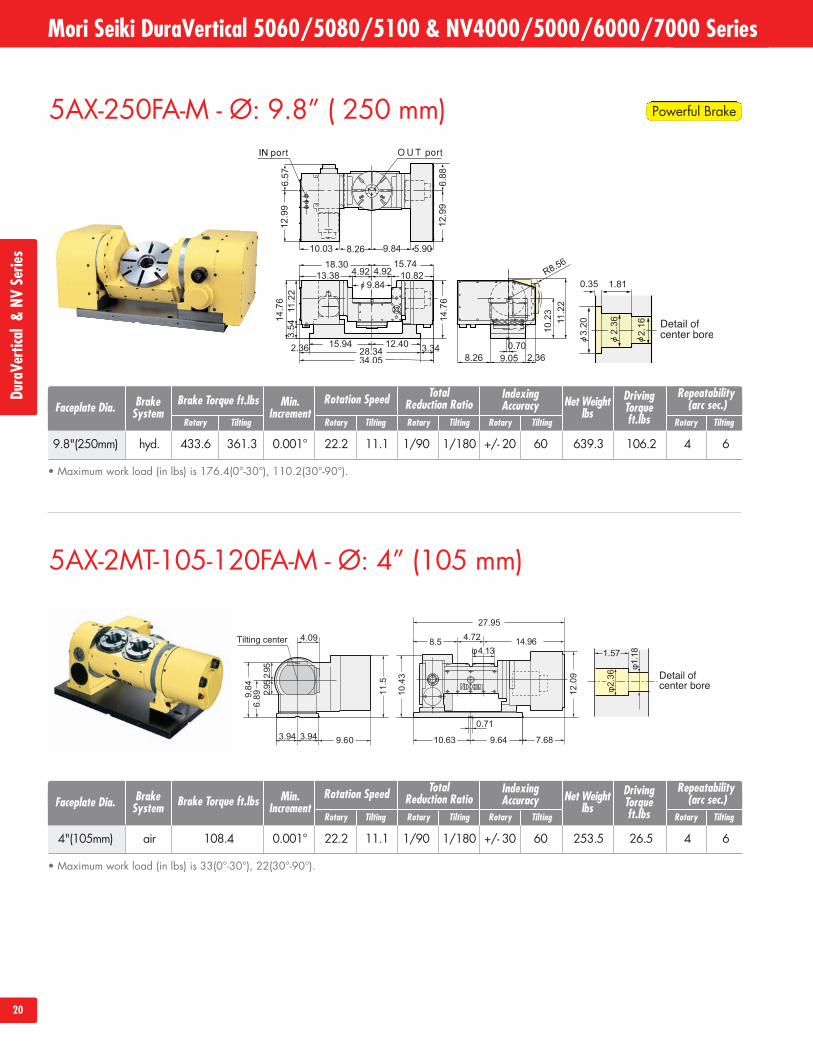
5AX-250FA-M - Ø: 9.8” ( 250 mm)
5AX-2MT-105-120FA-M - Ø: 4” (105 mm)
Mori Seiki DuraVertical 5060/5080/5100 & NV4000/5000/6000/7000 SeriesDu
raVe
rtical&NV
Serie
s
• Maximum work load (in lbs) is 176.4(0°-30°), 110.2(30°-90°).
9.8"(250mm) hyd. 433.6 361.3 0.001° 22.2 11.1 1/90 1/180 +/- 20 60 639.3 106.2 4 6
Faceplate Dia. Brake Torque ft.lbsTotal
Reduction Ratio Net Weightlbs
IndexingAccuracy
Repeatability(arc sec.)
DrivingTorqueft.lbs
Rotation SpeedBrakeSystem
Min.Increment
Rotary Tilting Rotary Tilting Rotary TiltingRotary Tilting Rotary Tilting
• Maximum work load (in lbs) is 33(0°-30°), 22(30°-90°).
4"(105mm) air 108.4 0.001° 22.2 11.1 1/90 1/180 +/- 30 60 253.5 26.5 4 6
Faceplate Dia. Brake Torque ft.lbsTotal
Reduction Ratio Net Weightlbs
IndexingAccuracy
Repeatability(arc sec.)
DrivingTorqueft.lbs
Rotation SpeedBrakeSystem
Min.Increment
Rotary Tilting Rotary Tilting Rotary Tilting Rotary Tilting
Powerful Brake
21
X-AXIS TRAVEL
Y-A
XIS
TRA
VE
L
C
X-TABLE SIZE
AY-T
AB
LES
IZE
B
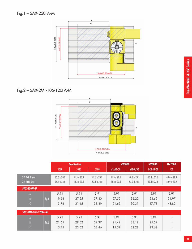
Fig.2 – 5AX-2MT-105-120FA-M
X-Y Axis Travel
X-Y Table Size
23.6 x 20.9
35.4 x 23.6
31.5 x 20.9
43.3 x 23.6
41.3 x 20.9
53.1 x 23.6
60.6 x 29.9
60.9 x 29.9
31.5 x 20.1
43.3 x 23.6
40.2 x 20.1
52.0 x 23.6
35.4 x 23.6
39.4 x 23.6
DuraVertical NV5000 NV6000
a1A40/50 a1B40/50 DCG 40/505060 5080 5100
5AX-250FA-M
5.91 5.91 5.91 5.91 5.91 5.91 5.91
19.68 27.55 37.40 27.55 36.22 23.62 51.97
13.78 21.65 31.49 21.65 30.31 17.71 48.82
A
B
C
fig.1
5AX-2MT-105-120FA-M
5.91 5.91 5.91 5.91 5.91 5.91 -
21.65 29.52 39.37 21.49 38.19 25.59 -
15.75 23.62 33.46 15.59 32.28 23.62 -
A
B
C
fig.2
Fig.1 – 5AX-250FA-M
NV7000
/50
DuraVe
rtical&NV
Serie
s
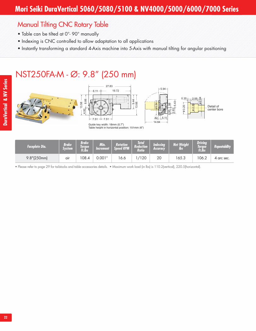
Manual Tilting CNC Rotary Table• Table can be tilted at 0°- 90° manually• Indexing is CNC controlled to allow adaptation to all applications• Instantly transforming a standard 4-Axis machine into 5-Axis with manual tilting for angular positioning
22
NST250FA-M - Ø: 9.8” (250 mm)
Mori Seiki DuraVertical 5060/5080/5100 & NV4000/5000/6000/7000 SeriesDu
raVe
rtical&NV
Serie
s
9.8"(250mm) air 108.4 0.001° 16.6 1/120 20 165.3 106.2 4 arc sec.
Faceplate Dia.BrakeTorqueft.lbs
TotalReductionRatio
Net Weightlbs
IndexingAccuracy Repeatability
DrivingTorqueft.lbs
• Please refer to page 29 for tailstocks and table accessories details. • Maximum work load (in lbs) is 110.2(vertical), 220.5(horizontal).
RotationSpeed RPM
BrakeSystem
Min.Increment
23
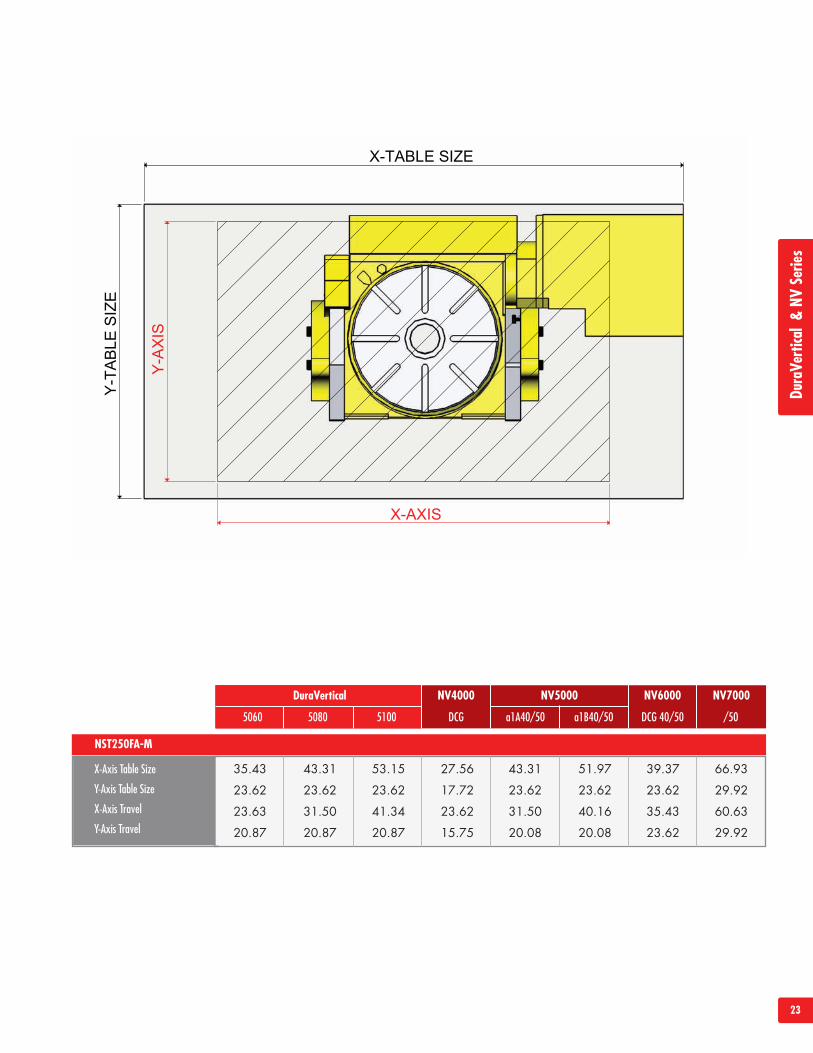
X-Axis Table Size
Y-Axis Table Size
X-Axis Travel
Y-Axis Travel
DuraVertical NV4000 NV5000 NV6000 NV7000
DCG a1A40/50 a1B40/50 DCG 40/50 /505060 5080 5100
NST250FA-M
35.43 43.31 53.15 27.56 43.31 51.97 39.37 66.93
23.62 23.62 23.62 17.72 23.62 23.62 23.62 29.92
23.63 31.50 41.34 23.62 31.50 40.16 35.43 60.63
20.87 20.87 20.87 15.75 20.08 20.08 23.62 29.92
DuraVe
rtical&NV
Serie
s
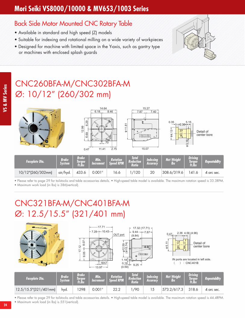
Back Side Motor Mounted CNC Rotary Table• Available in standard and high speed (Z) models• Suitable for indexing and rotational milling on a wide variety of workpieces• Designed for machine with limited space in the Y-axis, such as gantry type
or machines with enclosed splash guards
24
CNC321BFA-M/CNC401BFA-MØ: 12.5/15.5” (321/401 mm)
CNC260BFA-M/CNC302BFA-MØ: 10/12” (260/302 mm)
• Please refer to page 29 for tailstocks and table accessories details. • High-speed table model is available. The maximum rotation speed is 33.3RPM.• Maximum work load (in lbs) is 386(vertical).
Mori Seiki VS8000/10000 & MV653/1003 SeriesVS
&MVSerie
s
10/12"(260/302mm) air/hyd. 433.6 0.001° 16.6 1/120 20 308.6/319.6 141.6 4 arc sec.
Faceplate Dia.BrakeTorqueft.lbs
TotalReductionRatio
Net Weightlbs
IndexingAccuracy Repeatability
DrivingTorqueft.lbs
RotationSpeed RPM
BrakeSystem
Min.Increment
• Please refer to page 29 for tailstocks and table accessories details. • High-speed table model is available. The maximum rotation speed is 44.4RPM.• Maximum work load (in lbs) is 551(vertical).
12.5/15.5"(321/401mm) hyd. 1298 0.001° 22.2 1/90 15 573.2/617.3 318.6 4 arc sec.
Faceplate Dia.BrakeTorqueft.lbs
TotalReductionRatio
Net Weightlbs
IndexingAccuracy Repeatability
DrivingTorqueft.lbs
RotationSpeed RPM
BrakeSystem
Min.Increment
25
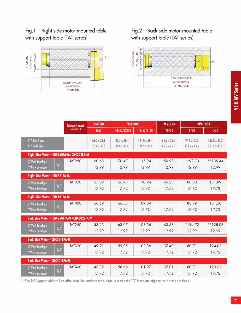
X-Y Axis Travel
X-Y Table Size
63.0 x 33.9
78.7 x 33.5
80.7 x 39.4
88.6 x 39.4
124.0 x 39.4
131.9 x 39.4
60.2 x 26.0
66.9 x 26.0
94.5 x 40.2
110.2 x 40.2
137.8 x 40.2
153.5 x 40.2
fig.1X-Work Envelope
Y-Work Envelope
VS8000 MV-653 MV-1003
40/50 B/50 L/505060 40/50/32050 40/50/3150
Right Side Motor - CNC260FA-M/CNC302FA-M
TAT250 60.63 70.47 115.94 50.98 **92.13 **135.44
12.99 12.99 12.99 12.99 12.99 12.99
VS10000Tailstock/SupportTable Part #
fig.1X-Work Envelope
Y-Work Envelope
Right Side Motor - CNC321FA-M
TAT320 57.09 66.93 110.24 45.28 88.58 131.89
17.72 17.72 17.72 17.72 17.72 17.72
fig.1X-Work Envelope
Y-Work Envelope
Right Side Motor - CNC401FA-M
TAT400 56.69 66.53 109.84 - 88.19 131.50
17.72 17.72 17.72 17.72 17.72 17.72
fig.2X-Work Envelope
Y-Work Envelope
Back Side Motor - CNC260BFA-M/CNC302BFA-M
TAT250 53.23 63.07 108.54 43.58 **84.72 **128.03
12.99 12.99 12.99 12.99 12.99 12.99
fig.2X-Work Envelope
Y-Work Envelope
Back Side Motor - CNC321BFA-M
TAT320 49.21 59.05 102.36 37.40 80.71 124.02
17.72 17.72 17.72 17.72 17.72 17.72
fig.2X-Work Envelope
Y-Work Envelope
Back Side Motor - CNC401BFA-M
TAT400 48.82 58.66 101.97 37.01 80.31 123.62
17.72 17.72 17.72 17.72 17.72 17.72
**The TAT support table will be offset from the machine table edge to match the TAT faceplate edge to the X-work envelope.
Fig.1 – Right side motor mounted tablewith support table (TAT series)
Fig.2 – Back side motor mounted tablewith support table (TAT series)
VS&MVSerie
s
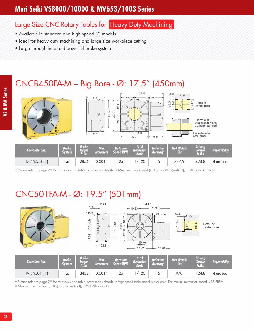
Large Size CNC Rotary Tables for Heavy Duty Machining• Available in standard and high speed (Z) models• Ideal for heavy duty machining and large size workpiece cutting• Large through hole and powerful brake system
26
CNCB450FA-M – Big Bore - Ø: 17.5” (450mm)
CNC501FA-M - Ø: 19.5” (501mm)
Mori Seiki VS8000/10000 & MV653/1003 SeriesVS
&MVSerie
s
• Please refer to page 29 for tailstocks and table accessories details. • Maximum work load (in lbs) is 771.6(vertical), 1543.2(horizontal).
17.5"(450mm) hyd. 2854 0.001° 25 1/120 15 727.5 424.8 4 arc sec.
Faceplate Dia.BrakeTorqueft.lbs
TotalReductionRatio
Net Weightlbs
IndexingAccuracy Repeatability
DrivingTorqueft.lbs
RotationSpeed RPM
BrakeSystem
Min.Increment
• Please refer to page 29 for tailstocks and table accessories details. • High-speed table model is available. The maximum rotation speed is 33.3RPM.• Maximum work load (in lbs) is 882(vertical), 1763.7(horizontal).
19.5"(501mm) hyd. 3433 0.001° 25 1/120 15 970 424.8 4 arc sec.
Faceplate Dia.BrakeTorqueft.lbs
TotalReductionRatio
Net Weightlbs
IndexingAccuracy Repeatability
DrivingTorqueft.lbs
RotationSpeed RPM
BrakeSystem
Min.Increment
27
11.411.96
10.82
35.7411.81 23.93
1.57 20.47
23.6
2
13.70
.78
24.0
112
.20
11.8
1
6.29
5.11
5.19
1.88.47
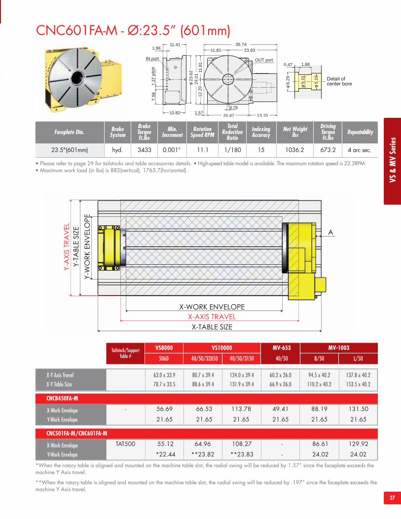
CNC601FA-M - Ø:23.5” (601mm)
X-Y Axis Travel
X-Y Table Size
63.0 x 33.9
78.7 x 33.5
80.7 x 39.4
88.6 x 39.4
124.0 x 39.4
131.9 x 39.4
60.2 x 26.0
66.9 x 26.0
94.5 x 40.2
110.2 x 40.2
137.8 x 40.2
153.5 x 40.2
X-Work Envelope
Y-Work Envelope
VS8000 MV-653 MV-1003
40/50 B/50 L/505060 40/50/32050 40/50/3150
CNCB450FA-M
- 56.69 66.53 113.78 49.41 88.19 131.50
21.65 21.65 21.65 21.65 21.65 21.65
VS10000Tailstock/SupportTable #
X-Work Envelope
Y-Work Envelope
CNC501FA-M/CNC601FA-M
TAT500 55.12 64.96 108.27 - 86.61 129.92
*22.44 **23.82 **23.83 - 24.02 24.02
*When the rotary table is aligned and mounted on the machine table slot, the radial swing will be reduced by 1.57” since the faceplate exceeds themachine Y Axis travel.
**When the rotary table is aligned and mounted on the machine table slot, the radial swing will be reduced by .197” since the faceplate exceeds themachine Y Axis travel.
VS&MVSerie
s
• Please refer to page 29 for tailstocks and table accessories details. • High-speed table model is available. The maximum rotation speed is 22.2RPM.• Maximum work load (in lbs) is 882(vertical), 1763.7(horizontal).
23.5"(601mm) hyd. 3433 0.001° 11.1 1/180 15 1036.2 673.2 4 arc sec.
Faceplate Dia.BrakeTorqueft.lbs
TotalReductionRatio
Net Weightlbs
IndexingAccuracy Repeatability
DrivingTorqueft.lbs
RotationSpeed RPM
BrakeSystem
Min.Increment
28
43.96.89
18.1114.174.7232.28
22.64
0.711.1810.04 11.42
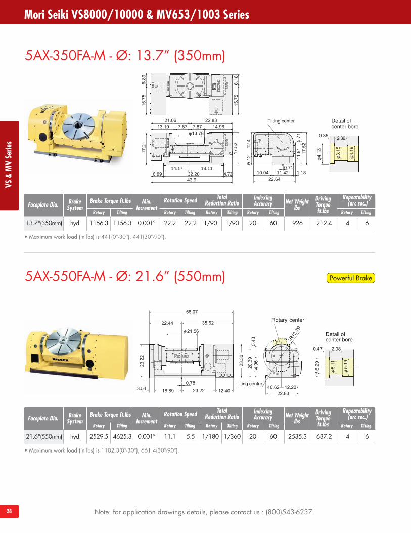
5AX-350FA-M - Ø: 13.7” (350mm)
5AX-550FA-M - Ø: 21.6” (550mm)
Mori Seiki VS8000/10000 & MV653/1003 SeriesVS
&MVSerie
s
• Maximum work load (in lbs) is 441(0°-30°), 441(30°-90°).
13.7"(350mm) hyd. 1156.3 1156.3 0.001° 22.2 22.2 1/90 1/90 20 60 926 212.4 4 6
Faceplate Dia. Brake Torque ft.lbsTotal
Reduction Ratio Net Weightlbs
IndexingAccuracy
Repeatability(arc sec.)
DrivingTorqueft.lbs
Rotation SpeedBrakeSystem
Min.Increment
Rotary Tilting Rotary Tilting Rotary TiltingRotary Tilting Rotary Tilting
• Maximum work load (in lbs) is 1102.3(0°-30°), 661.4(30°-90°).
21.6"(550mm) hyd. 2529.5 4625.3 0.001° 11.1 5.5 1/180 1/360 20 60 2535.3 637.2 4 6
Faceplate Dia. Brake Torque ft.lbsTotal
Reduction Ratio Net Weightlbs
IndexingAccuracy
Repeatability(arc sec.)
DrivingTorqueft.lbs
Rotation SpeedBrakeSystem
Min.Increment
Rotary Tilting Rotary Tilting Rotary TiltingRotary Tilting Rotary Tilting
Powerful Brake
Note: for application drawings details, please contact us : (800)543-6237.
Accessories
29
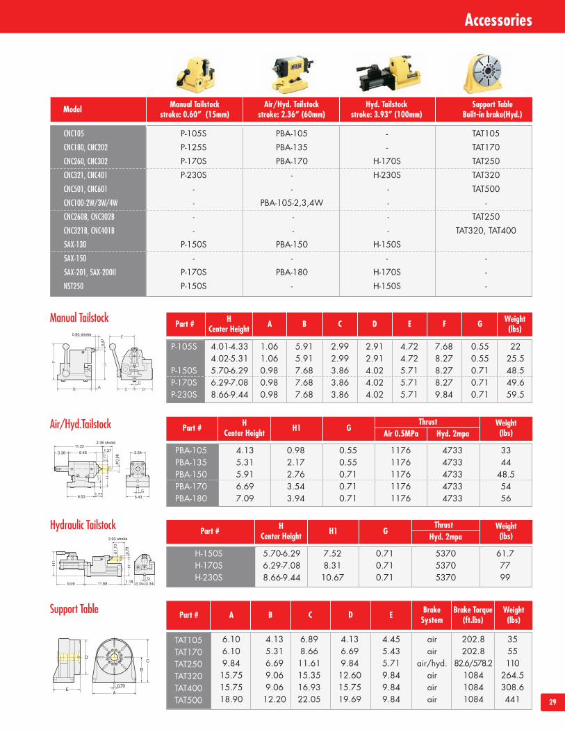
Model
P-105S PBA-105 - TAT105P-125S PBA-135 - TAT170P-170S PBA-170 H-170S TAT250P-230S - H-230S TAT320
- - - TAT500- PBA-105-2,3,4W - -- - - TAT250- - - TAT320, TAT400
P-150S PBA-150 H-150S- - - -
P-170S PBA-180 H-170S -P-150S - H-150S -
Manual Tailstockstroke: 0.60” (15mm)
Air/Hyd. Tailstockstroke: 2.36” (60mm)
Hyd. Tailstockstroke: 3.93” (100mm)
Support TableBuilt-in brake(Hyd.)
CNC105
CNC180, CNC202
CNC260, CNC302
CNC321, CNC401
CNC501, CNC601
CNC100-2W/3W/4W
CNC260B, CNC302B
CNC321B, CNC401B
5AX-130
5AX-150
5AX-201, 5AX-200II
NST250
HCenter Height A B C D E F G Weight
(lbs)Part #
4.01-4.33 1.06 5.91 2.99 2.91 4.72 7.68 0.55 224.02-5.31 1.06 5.91 2.99 2.91 4.72 8.27 0.55 25.55.70-6.29 0.98 7.68 3.86 4.02 5.71 8.27 0.71 48.56.29-7.08 0.98 7.68 3.86 4.02 5.71 8.27 0.71 49.68.66-9.44 0.98 7.68 3.86 4.02 5.71 9.84 0.71 59.5
P-105S
P-150SP-170SP-230S
HCenter Height H1 G
Air 0.5MPaThrust Weight
(lbs)Part #Hyd. 2mpa
4.13 0.98 0.55 1176 4733 335.31 2.17 0.55 1176 4733 445.91 2.76 0.71 1176 4733 48.56.69 3.54 0.71 1176 4733 547.09 3.94 0.71 1176 4733 56
PBA-105PBA-135PBA-150PBA-170PBA-180
HCenter Height H1 G
Thrust Weight(lbs)Part #
Hyd. 2mpa
5.70-6.29 7.52 0.71 5370 61.76.29-7.08 8.31 0.71 5370 778.66-9.44 10.67 0.71 5370 99
H-150SH-170SH-230S
A B C D EPart #
6.10 4.13 6.89 4.13 4.45 air 202.8 356.10 5.31 8.66 6.69 5.43 air 202.8 559.84 6.69 11.61 9.84 5.71 air/hyd. 82.6/578.2 11015.75 9.06 15.35 12.60 9.84 air 1084 264.515.75 9.06 16.93 15.75 9.84 air 1084 308.618.90 12.20 22.05 19.69 9.84 air 1084 441
TAT105TAT170TAT250TAT320TAT400TAT500
Manual Tailstock
Air/Hyd.Tailstock
Hydraulic Tailstock
Support Table BrakeSystem
Brake Torque(ft.lbs)
Weight(lbs)
30
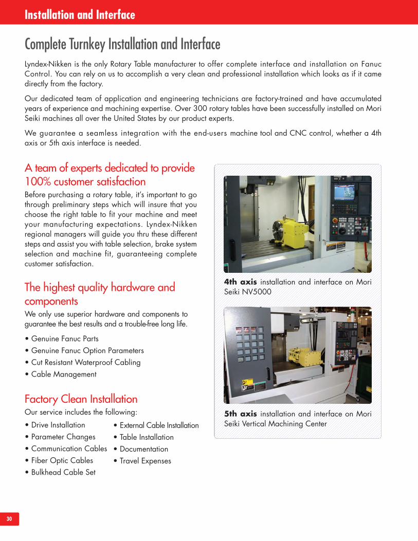
Lyndex-Nikken is the only Rotary Table manufacturer to offer complete interface and installation on FanucControl. You can rely on us to accomplish a very clean and professional installation which looks as if it camedirectly from the factory.
Our dedicated team of application and engineering technicians are factory-trained and have accumulatedyears of experience and machining expertise. Over 300 rotary tables have been successfully installed on MoriSeiki machines all over the United States by our product experts.
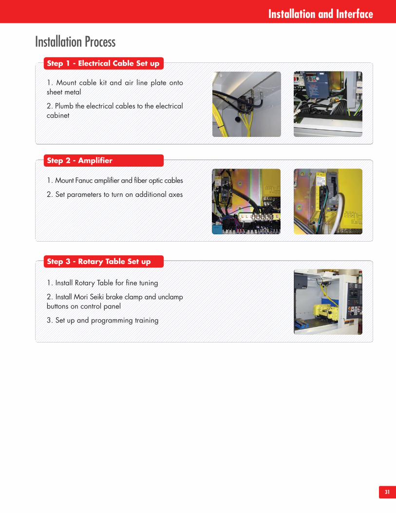
We guarantee a seamless integration with the end-users machine tool and CNC control, whether a 4thaxis or 5th axis interface is needed.
A team of experts dedicated to provide100% customer satisfactionBefore purchasing a rotary table, it’s important to gothrough preliminary steps which will insure that youchoose the right table to fit your machine and meetyour manufacturing expectations. Lyndex-Nikkenregional managers will guide you thru these differentsteps and assist you with table selection, brake systemselection and machine fit, guaranteeing completecustomer satisfaction.
The highest quality hardware andcomponentsWe only use superior hardware and components toguarantee the best results and a trouble-free long life.
• Genuine Fanuc Parts• Genuine Fanuc Option Parameters• Cut Resistant Waterproof Cabling• Cable Management
Factory Clean InstallationOur service includes the following:
• Drive Installation• Parameter Changes• Communication Cables• Fiber Optic Cables• Bulkhead Cable Set
• External Cable Installation• Table Installation• Documentation• Travel Expenses
Complete Turnkey Installation and Interface
4th axis installation and interface on MoriSeiki NV5000
5th axis installation and interface on MoriSeiki Vertical Machining Center
Installation and Interface
31
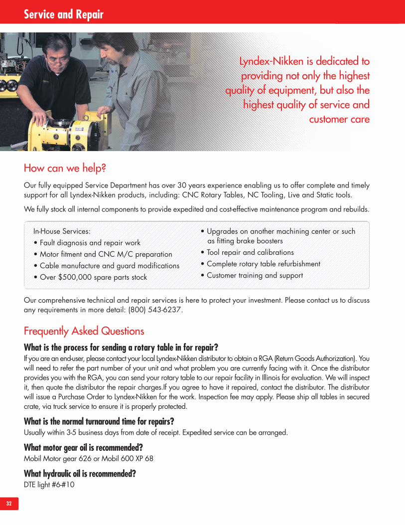
Installation ProcessStep 1 - Electrical Cable Set up
Step 2 - Amplifier
Step 3 - Rotary Table Set up
1. Mount cable kit and air line plate ontosheet metal
2. Plumb the electrical cables to the electricalcabinet
1. Mount Fanuc amplifier and fiber optic cables
2. Set parameters to turn on additional axes
1. Install Rotary Table for fine tuning
2. Install Mori Seiki brake clamp and unclampbuttons on control panel
3. Set up and programming training
Installation and Interface
32
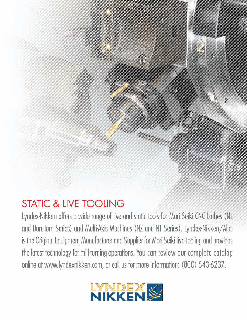
Service and Repair
How can we help?Our fully equipped Service Department has over 30 years experience enabling us to offer complete and timelysupport for all Lyndex-Nikken products, including: CNC Rotary Tables, NC Tooling, Live and Static tools.
We fully stock all internal components to provide expedited and cost-effective maintenance program and rebuilds.
Our comprehensive technical and repair services is here to protect your investment. Please contact us to discussany requirements in more detail: (800) 543-6237.
Frequently Asked QuestionsWhat is the process for sending a rotary table in for repair?If youare an end-user, please contact your local Lyndex-Nikkendistributor to obtain a RGA (ReturnGoodsAuthorization). Youwill need to refer the part number of your unit and what problem you are currently facing with it. Once the distributorprovides you with the RGA, you can send your rotary table to our repair facility in Illinois for evaluation.We will inspectit, then quote the distributor the repair charges.If you agree to have it repaired, contact the distributor. The distributorwill issue a Purchase Order to Lyndex-Nikken for the work. Inspection fee may apply. Please ship all tables in securedcrate, via truck service to ensure it is properly protected.
What is the normal turnaround time for repairs?Usually within 3-5 business days from date of receipt. Expedited service can be arranged.
What motor gear oil is recommended?Mobil Motor gear 626 or Mobil 600 XP 68
What hydraulic oil is recommended?DTE light #6-#10
In-House Services:• Fault diagnosis and repair work• Motor fitment and CNC M/C preparation• Cable manufacture and guard modifications• Over $500,000 spare parts stock
• Upgrades on another machining center or suchas fitting brake boosters
• Tool repair and calibrations• Complete rotary table refurbishment• Customer training and support
Lyndex-Nikken is dedicated toproviding not only the highest
quality of equipment, but also thehighest quality of service and
customer care
STATIC & LIVE TOOLINGLyndex-Nikken offers a wide range of live and static tools for Mori Seiki CNC Lathes (NLand DuraTurn Series) and Multi-Axis Machines (NZ and NT Series). Lyndex-Nikken/Alpsis the Original Equipment Manufacturer and Supplier for Mori Seiki live tooling and providesthe latest technology for mill-turning operations. You can review our complete catalogonline at www.lyndexnikken.com, or call us for more information: (800) 543-6237.

www.lyndexnikken.com(800) 543-6237CAT2010-MORI-RT