Embed Size (px)
Citation preview
BNACNC Turning center
Miyano Innovation Line
BNA-34/42
2
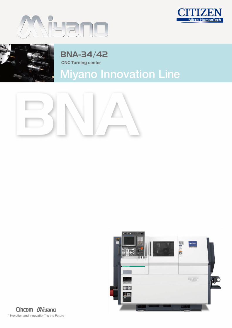
The BNA series packs sophisticated functions and high accuracy into a space-saving compact body.It represents Evolution and Innovation.The lineup includes models in three versions.
3
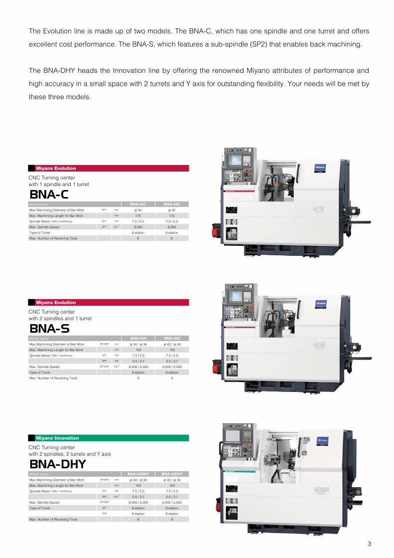
The Evolution line is made up of two models. The BNA-C, which has one spindle and one turret and offers
excellent cost performance. The BNA-S, which features a sub-spindle (SP2) that enables back machining.
The BNA-DHY heads the Innovation line by offering the renowned Miyano attributes of performance and
high accuracy in a small space with 2 turrets and Y axis for outstanding flexibility. Your needs will be met by
these three models.
Model Name BNA-34C BNA-42C
Max Machining Diameter of Bar Work SP1 mm φ34 φ42
Max. Machining Length for Bar Work mm 175 175
Spindle Motor(15Min. Cont/Rating) SP1 kW 7.5 / 5.5 7.5 / 5.5
Max. Spindle Speed SP1 min-1 6,000 6,000
Type of Turret 8-station 8-station
Max. Number of Revolving Tools 8 8
CNC Turning centerwith 1 spindle and 1 turret
BNA-C
CNC Turning centerwith 2 spindles and 1 turret
BNA-SModel Name BNA-34S BNA-42S
Max Machining Diameter of Bar Work SP1/SP2 mm φ34 / φ34 φ42 / φ34
Max. Machining Length for Bar Work mm 100 100
Spindle Motor(15Min. Cont/Rating) SP1 kW 7.5 / 5.5 7.5 / 5.5
SP2 kW 5.5 / 3.7 5.5 / 3.7
Max. Spindle Speed SP1/SP2 min-1 6,000 / 5,000 6,000 / 5,000
Type of Turret 8-station 8-station
Max. Number of Revolving Tools 8 8
CNC Turning centerwith 2 spindles, 2 turrets and Y axis
BNA-DHYModel Name BNA-34DHY BNA-42DHY
Max Machining Diameter of Bar Work SP1/SP2 mm φ34 / φ34 φ42 / φ34
Max. Machining Length for Bar Work mm 100 100
Spindle Motor(15Min. Cont/Rating SP1 kW 7.5 / 5.5 7.5 / 5.5
SP2 min-1 5.5 / 3.7 5.5 / 3.7
Max. Spindle Speed SP1/SP2 6,000 / 5,000 6,000 / 5,000
Type of Turret SP1 8-station 8-station
SP2 6-station 6-station
Max. Number of Revolving Tools 8 8
4
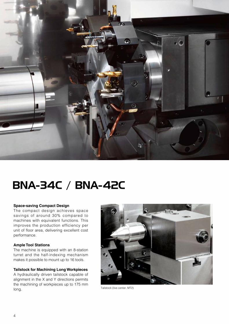
Space-saving Compact DesignThe compact design achieves space savings of around 30% compared to machines with equivalent functions. This improves the production efficiency per unit of floor area, delivering excellent cost performance.
Ample Tool StationsThe machine is equipped with an 8-station turret and the half-indexing mechanism makes it possible to mount up to 16 tools.
Tailstock for Machining Long WorkpiecesA hydraulically driven tailstock capable of alignment in the X and Y directions permits the machining of workpieces up to 175 mm long. Tailstock (live center, MT2)
BNA-34C / BNA-42C
5
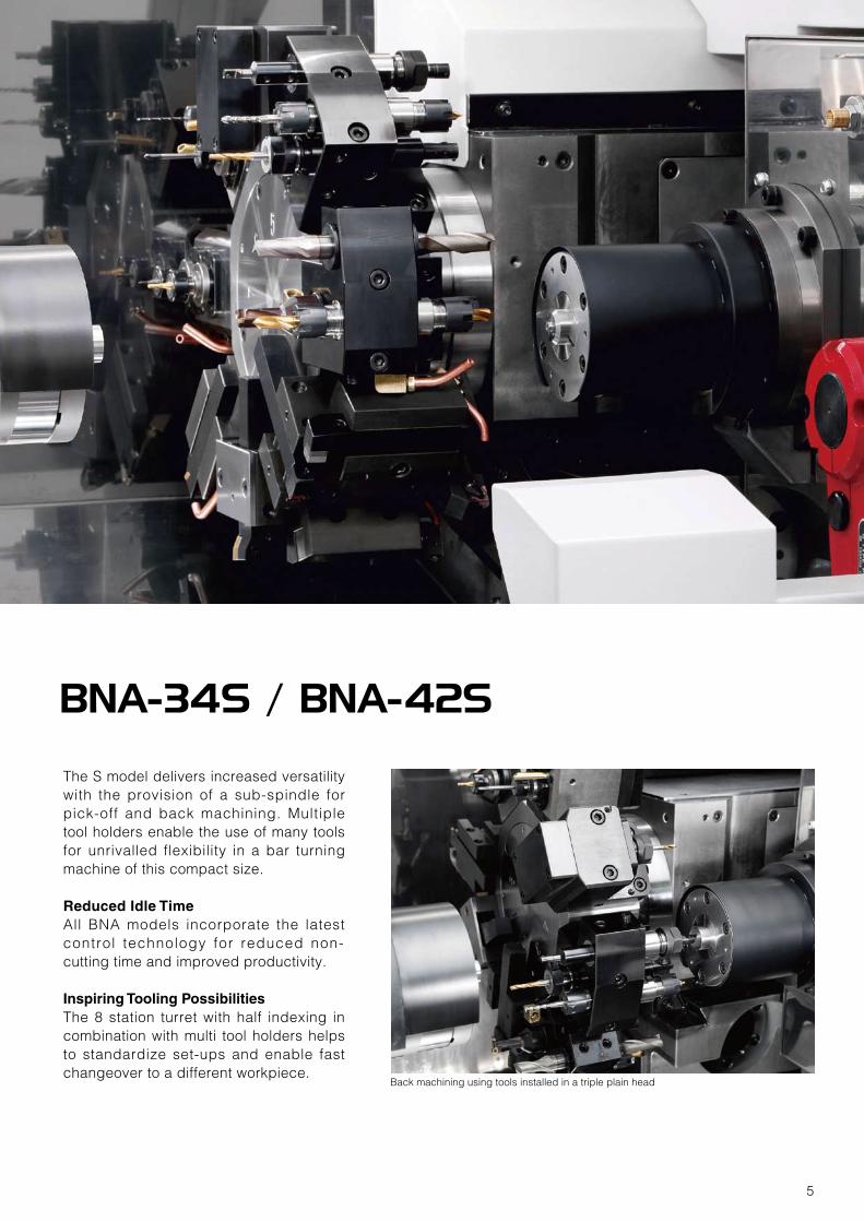
The S model delivers increased versatility with the provision of a sub-spindle for pick-off and back machining. Multiple tool holders enable the use of many tools for unrivalled flexibility in a bar turning machine of this compact size.
Reduced Idle TimeAll BNA models incorporate the latest control technology for reduced non-cutting time and improved productivity.
Inspiring Tooling PossibilitiesThe 8 station turret with half indexing in combination with multi tool holders helps to standardize set-ups and enable fast changeover to a different workpiece.
Back machining using tools installed in a triple plain head
BNA-34S / BNA-42S
6
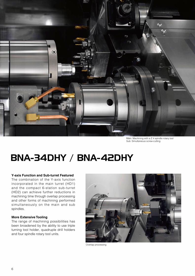
Y-axis Function and Sub-turret FeaturedThe combination of the Y-axis function incorporated in the main turret (HD1) and the compact 6-station sub-turret (HD2) can achieve further reductions in machining time through overlap processing and other forms of machining performed simultaneously on the main and sub spindles.
More Extensive ToolingThe range of machining possibilities has been broadened by the ability to use triple turning tool holder, quadruple drill holders and four spindle rotary tool units.
Overlap processing
BNA-34DHY / BNA-42DHY
Main: Machining with a Z 4 spindle rotary toolSub: Simultaneous screw-cutting
7
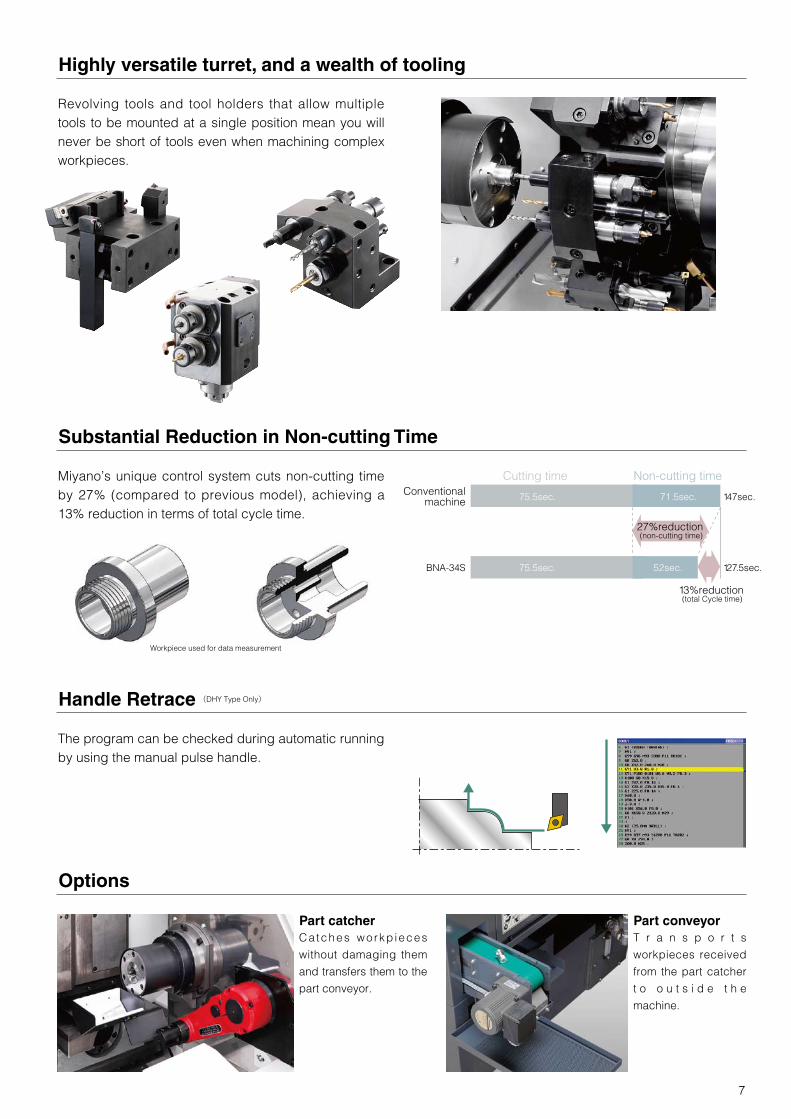
Highly versatile turret, and a wealth of tooling
Revolving tools and tool holders that allow multiple tools to be mounted at a single position mean you will never be short of tools even when machining complex workpieces.
Substantial Reduction in Non-cutting Time
Miyano’s unique control system cuts non-cutting time by 27% (compared to previous model), achieving a 13% reduction in terms of total cycle time.
Workpiece used for data measurement
Options
Part catcherCatches workp ieces
without damaging them
and transfers them to the
part conveyor.
Part conveyorT r a n s p o r t s
workpieces received
from the part catcher
t o o u t s i d e t h e
machine.
Handle Retrace
The program can be checked during automatic running by using the manual pulse handle.
(DHY Type Only)
Cutting time Non-cutting timeConventional
machine
BNA-34S
147sec.
127.5sec.
75.5sec. 71.5sec.
27%reduction (non-cutting time)
13%reduction (total Cycle time)
75.5sec. 52sec.
8
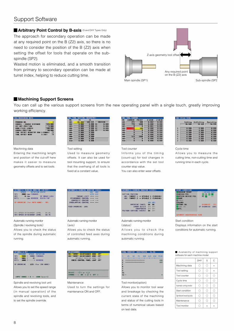
Support Software
■Arbitrary Point Control by B-axis (S and DHY Types Only)
The approach for secondary operation can be made at any required point on the B (Z2) axis, so there is no need to consider the position of the B (Z2) axis when setting the offset for tools that operate on the sub-spindle (SP2).Wasted motion is eliminated, and a smooth transition from primary to secondary operation can be made at turret index, helping to reduce cutting time.
■Machining Support ScreensYou can call up the various support screens from the new operating panel with a single touch, greatly improving working efficiency.
Machining data
Entering the machining length
and position of the cut-off here
makes i t eas ier to measure
geometry offsets and to set tools.
Tool setting
Used to measure geomet ry
offsets. It can also be used for
tool mounting support, to ensure
that the overhang of all tools is
fixed at a constant value.
Tool counter
I n f o r m s y o u o f t h e t i m i n g
(count-up) for tool changes in
accordance with the set tool
counter stop value.
You can also enter wear offsets.
Cycle time
A l lows you to measure the
cutting time, non-cutting time and
running time in each cycle.
Start condition
Displays information on the start
conditions for automatic running.
Spindle and revolving tool unit
Allows you to set the speed range
( in manual operation) of the
spindle and revolving tools, and
to set the spindle override.
Maintenance
Used to turn the settings for
maintenance ON and OFF.
Tool monitor(option)
Allows you to monitor tool wear
and breakage by checking the
current state of the machining
and status of the cutting tools in
terms of numerical values based
on test data.
Automatic running monitor
(Spindle / revolving tools)
Allows you to check the status
of the spindle during automatic
running.
Automatic running monitor
(axis)
Allows you to check the status
of controlled feed axes during
automatic running.
Automatic running monitor
(status)
A l l o w s y o u t o c h e c k t h e
machining conditions during
automatic running.
DHY S C
Machining data ○ ○ ×
Tool setting ○ ○ ×
Tool counter ○ ○ ○
Cycle time ○ ○ ○
Automatic running monitor ○ ○ ○
Start condition ○ ○ ○
Spindle and revolving tools ○ ○ ○
Maintenance ○ ○ ○
Tool monitor ○ × ×
■ Availabil i ty of machining support software for each machine model
Z-axis geometry tool offset
Sub-spindle (SP2)Main spindle (SP1)
Any required point on the B (Z2) axis
9
B Stroke 310
6966
20
37 35
2-φ25
35
44
44
X Stroke
135
8st. H200
135
78
30
φ390
59
Zストローク 235129
φ115
φ135
Main spindle
Sub spindle
Collet chuck
5" Power chuck
414417 148.5
Tailstock
37 35
2-φ25
35
44
44
X Stroke
135
8st. H200
135
φ390
59
φ115
φ135
Main spindle
Collet chuck
5" Power chuck
Z Stroke 235
Tailstock stroke
129
20
259256
175
6966
φ190
φ25
69
66
129 235 78
Z1 Stroke
Z2 Stroke 310 14.1
3535
417
414
148.5
129
11
X2 Stroke
140
Y Stroke 70
8St. H200
φ405
140
X1 Stroke
44
1919
35
100135
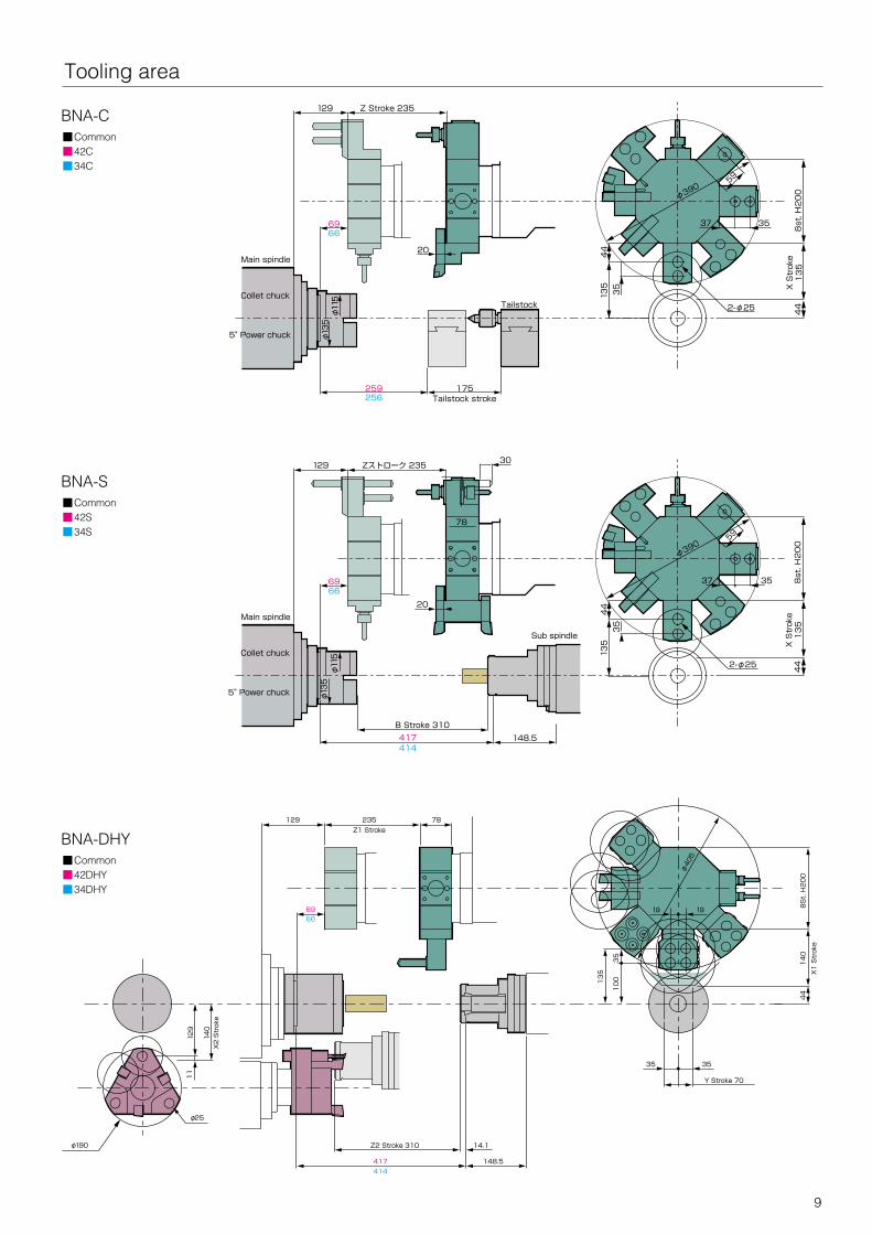
Tooling area
BNA-DHY ■Common ■42DHY ■34DHY
BNA-S ■Common ■42S ■34S
BNA-C ■Common ■42C ■34C
10
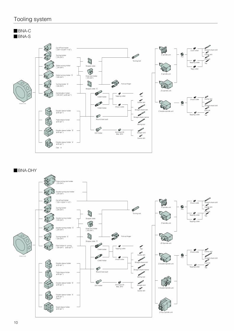
Tooling system
Triple sleeve holderφ25 (φ1”)
Double sleeve holderφ25 (φ1”)
Drill bush 20Max. Ø12
Drill holder
Round hole bush
Collet holder
Tapping colletCollet holder
Center drill
Center drill
Straight drill
Straight shank drill
Boring tool
Tap
Straight shank reamer
Double turning holder□20 (3/4”)
Turning holder‘S’□20 (3/4”)
Cut off tool holder□20×12(3/4”×1/2”)
Turning tool
Z Double Spindle unit
Nut
Center drillChuck collet
Tapping collet Tap
End mill
Straight shank drill
Chuck collet
Tapping collet
X Spindle unit
Z Spindle unit
Nut
Tap
Center drill
End mill
Straight shank drill
Tapping collet
Knee tool holder□20 (3/4”)
Stopper plate
ZS Spindle unit
Chuck collet
Double turning holder‘S’□20 (3/4”)
Turning holder□20 (3/4”)
Stopper plate‘S’
Double sleeve holder‘A’φ25 (φ1”)
Plain holder & turning□20 (3/4”) φ25 (φ1”)
Double sleeve holder‘D’φ25 (φ1”)
Cap A
Quad sleeve holder φ25 (φ1”)
Double turning tool holder□20 (3/4”)
Tliple turning tool holder□20 (3/4”)
X Double Spindle unit
Z Four Spindle unit
8 Station turret
Pull out finger
Triple sleeve holderφ25 (φ1”)
Double sleeve holderφ25 (φ1”)
Drill bush 20Max. Ø12
Drill holder
Round hole bush
Collet holder
Tapping colletCollet holder
Center drill
Center drill
Straight drill
Straight shank drill
Boring tool
Tap
Straight shank raemer
Doble turning holder□20 (3/4”)
Turning holder‘S’□20 (3/4”)
Cut off tool holder□20×12 (3/4”×1/2”)
Turning tool
Z double spindle unit
Nut
Center drillChuck collet
Tapping collet Tap
End mill
Straight shank drill
Cuck collet
Tapping collet
X spindle unit
Z spindle unit
Nut
Tap
Center drill
End mill
Straight shank drill
Tapp collet
Knee tool holder□20 (3/4”)
Stopper plate
ZS spindle unit
Chuck collet
Doble turning holder‘S’□20 (3/4”)
Turning holder□20 (3/4”)
Stopper plate‘S’
Double sleeve holder‘A’φ25 (φ1”)
Combination holder□20 (3/4”) φ25 (φ1”)
Double sleeve holder‘D’φ25 (φ1”)
Cap A
8 Station turret
Pull out finger
■BNA-DHY
■BNA-C■BNA-S
11
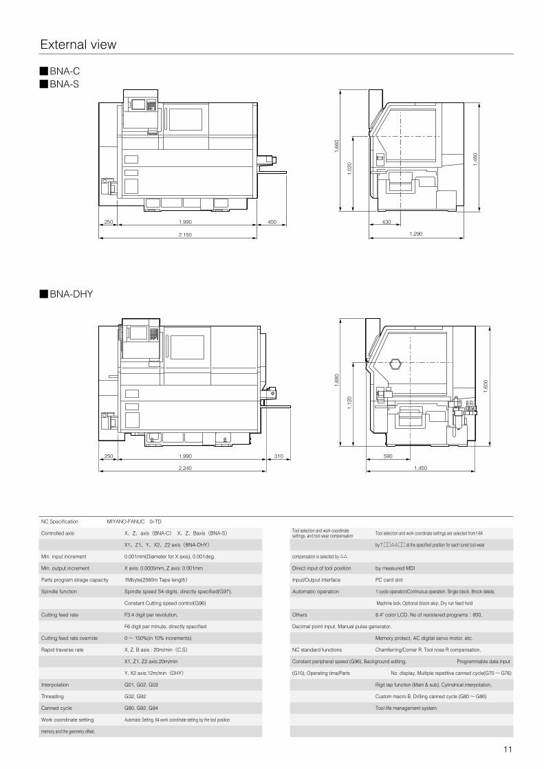
External view
Controlled axis X、Z、axis(BNA-C) X、Z、Baxis(BNA-S)
X1、Z1、Y、X2、Z2 axis(BNA-DHY)
Min. input increment 0.001mm(Diameter for X axis), 0.001deg.
Min. output increment X axis: 0.0005mm, Z axis: 0.001mm
Parts program strage capacity 1Mbyte(2560m Tape length)
Spindle function Spindle speed S4-digits, directly specified(G97),
Constant Cutting speed control(G96)
Cutting feed rate F3.4 digit per revolution,
F6 digit per minute, directly specified
Cutting feed rate override 0 〜 150%(in 10% increments)
Rapid traverse rate X, Z, B asis : 20m/min(C,S)
X1, Z1, Z2 axis:20m/min
Y, X2 axis:12m/min(DHY)
Interpolation G01, G02, G03
Threading G32, G92
Canned cycle G90, G92, G94
Work coordinate setting Automatic Setting, 64 work coordinate setting by the tool position
memory and the geometry offset.
Tool selection and work coordinate Tool selection and work coordinate settings are selected from1-64settings, and tool wear compensation
by T □□△△□□ at the specified position for each turret tool wear
compensation is selected by △△ .
Direct input of tool position by measured MDI
Input/Output interface PC card slot
Automatic operation 1 cycle operation/Continuous operation, Single block, Brock delete,
Machine lock, Optional block skip, Dry run feed hold
Others 8.4" color LCD, No of resistered programs:800,
Decimal point input, Manual pulse generator,
Memory protect, AC digital servo motor, etc.
NC standard functions Chamferring/Corner R, Tool nose R compensation,
Constant peripheral speed (G96), Background editing, Programmable data input
(G10), Operating time/Parts No. display, Multiple repetitive canned cycle(G70 〜 G76)
Rigit tap function (Main & sub), Cylindrical interpolation,
Custom macro B, Drilling canned cycle (G80 〜 G86)
Tool life management system.
NC Specification MIYANO-FANUC 0i-TD
1,990
1,990
1,12
01,
020
1,68
0
1,60
0
1,48
0
1,66
0
2,240
2,150
1,450
1,290
310
400
590
430
250
250
■BNA-DHY
■BNA-C■BNA-S
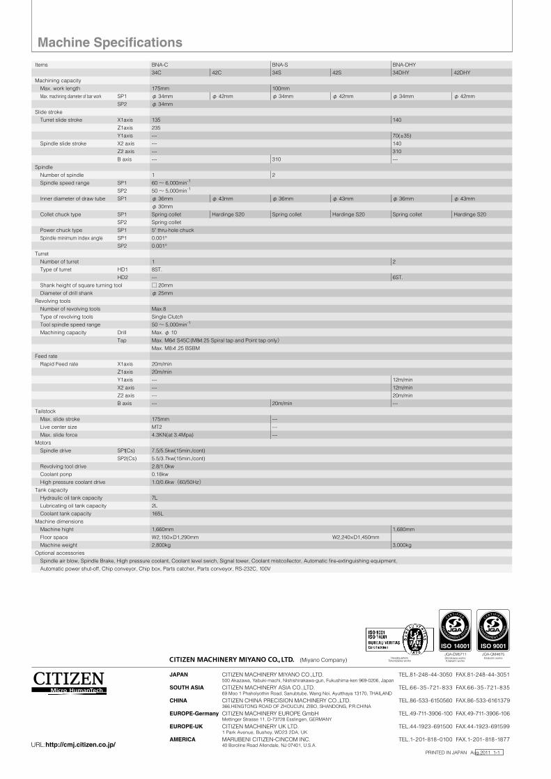
Items BNA-C BNA-S BNA-DHY
34C 42C 34S 42S 34DHY 42DHY
Machining capacity
Max. work length 175mm 100mm
Max. machining diameter of bar work SP1 φ 34mm φ 42mm φ 34mm φ 42mm φ 34mm φ 42mm
SP2 φ 34mm
Slide stroke
Turret slide stroke X1axis 135 140
Z1axis 235
Y1axis --- 70(±35)
Spindle slide stroke X2 axis --- 140
Z2 axis --- 310
B axis --- 310 ---
Spindle
Number of spindle 1 2
Spindle speed range SP1 60 〜 6,000min-1
SP2 50 〜 5,000min-1
Inner diameter of draw tube SP1 φ 36mm φ 43mm φ 36mm φ 43mm φ 36mm φ 43mm
φ 30mm
Collet chuck type SP1 Spring collet Hardinge S20 Spring collet Hardinge S20 Spring collet Hardinge S20
SP2 Spring collet
Power chuck type SP1 5" thru-hole chuck
Spindle minimum index angle SP1 0.001°
SP2 0.001°
Turret
Number of turret 1 2
Type of turret HD1 8ST.
HD2 --- 6ST.
Shank height of square turning tool □ 20mm
Diameter of drill shank φ 25mm
Revolving tools
Number of revolving tools Max.8
Type of revolving tools Single Clutch
Tool spindle speed range 50 〜 5,000min-1
Machining capacity Drill Max. φ 10
Tap Max. M6×1 S45C (M8×1.25 Spiral tap and Point tap only) Max. M8×1.25 BSBM
Feed rate
Rapid Feed rate X1axis 20m/min
Z1axis 20m/min
Y1axis --- 12m/min
X2 axis --- 12m/min
Z2 axis --- 20m/min
B axis --- 20m/min ---
Tailstock
Max. slide stroke 175mm ---
Live center size MT2 ---
Max. slide force 4.3KN(at 3.4Mpa) ---
Motors
Spindle drive SP1(Cs) 7.5/5.5kw(15min./cont)
SP2(Cs) 5.5/3.7kw(15min./cont)
Revolving tool drive 2.8/1.0kw
Coolant ponp 0.18kw
High pressure coolant drive 1.0/0.6kw(60/50Hz)Tank capacity
Hydraulic oil tank capacity 7L
Lubricating oil tank capacity 2L
Coolant tank capacity 165L
Machine dimensions
Machine hight 1,660mm 1,680mm
Floor space W2,150×D1,290mm W2,240×D1,450mm
Machine weight 2,800kg 3,000kg
Optional accessories
Spindle air blow, Spindle Brake, High pressure coolant, Coolant level swich, Signal tower, Coolant mistcollector, Automatic fire-extinguishing equipment,
Automatic power shut-off, Chip conveyor, Chip box, Parts catcher, Parts conveyor, RS-232C, 100V
PRINTED IN JAPAN Aug.2011 1-1
Machine Specifications
All specifications are subject to change without prior notice. This product is an export control item subject to the foreign exchange and foreign trade act. Thus, before exporting this product, or taking it overseas, contact your CITIZEN machine dealer. Please inform your CITIZEN machine dealer in advance of your intention to re-sell, export or relocate this products. For the avoidance of doubt products includes whole or part, replica or copy, technologies and software. In the event of export, proof of approval to export by government or regulatory authority must be evidenced to CITIZEN. You can operate the machines after the confirmation of CITIZEN.CITIZEN is a registered trademark of Citizen Holdings Co., Japan.
JAPAN CITIZEN MACHINERY MIYANO CO.,LTD. TEL.81-248-44-3050 FAX.81-248-44-3051 500 Akazawa, Yabuki-machi, Nishishirakawa-gun, Fukushima-ken 969-0206, Japan
SOUTH ASIA CITIZEN MACHINERY ASIA CO.,LTD. TEL.66 -35 -721-833 FAX.66-35 -721-835 69 Moo 1 Phaholyothin Road, Sanubtube, Wang Noi, Ayutthaya 13170, THAILAND
CHINA CITIZEN CHINA PRECISION MACHINERY CO.,LTD. TEL.86-533-6150560 FAX.86-533-6161379 366,HENGTONG ROAD OF ZHOUCUN, ZIBO, SHANDONG, P.R.CHINA
EUROPE-Germany CITIZEN MACHINERY EUROPE GmbH TEL.49-711-3906-100 FAX.49-711-3906-106 Mettinger Strasse 11, D-73728 Esslingen, GERMANY
EUROPE-UK CITIZEN MACHINERY UK LTD. TEL.44-1923-691500 FAX.44-1923-691599 1 Park Avenue, Bushey, WD23 2DA, UK
AMERICA MARUBENI CITIZEN-CINCOM INC. TEL.1-201-818-0100 FAX.1-201- 818-1877 40 Boroline Road Allendale, NJ 07401, U.S.A.
HeadquartersTokorozawa works
Shirakawa worksKitakami works
Kitakami works
URL:http://cmj.citizen.co.jp/
(Miyano Company)