Embed Size (px)
Citation preview
PRECISION CNC LATHECNC MULTI-TASKING TURNING CENTER
To reserch and improve, our company keep the right of changing designs and specifications without further notice.
No.48-26, Xilin Ln., Xitun Dist., Taichung City 407, TaiwanTEL: +886-4-2463 0182 E-mail:[email protected]: +886-4-2463 8910 http://www.selica.com.tw
Note:
Agents:
201611 886-4-24793348 / 1000
01 02
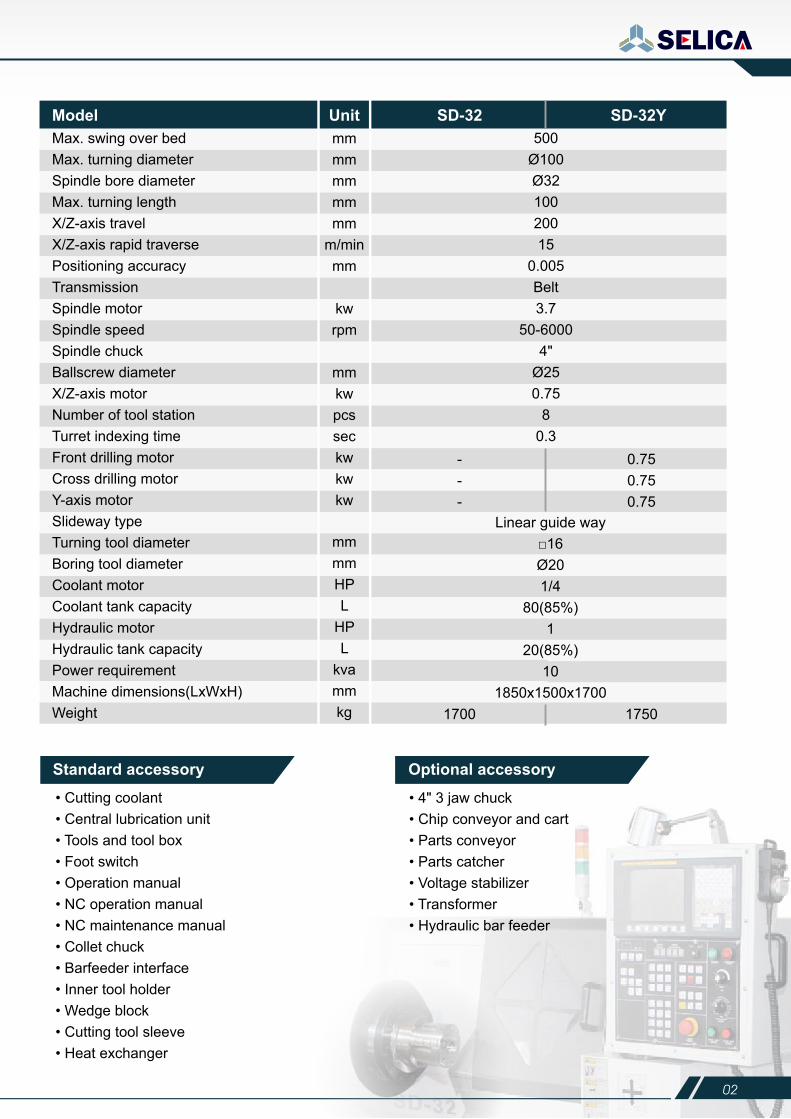
Max. swing over bedMax. turning diameterSpindle bore diameterMax. turning lengthX/Z-axis travelX/Z-axis rapid traversePositioning accuracyTransmissionSpindle motorSpindle speedSpindle chuckBallscrew diameterX/Z-axis motorNumber of tool stationTurret indexing timeFront drilling motorCross drilling motorY-axis motorSlideway typeTurning tool diameterBoring tool diameterCoolant motorCoolant tank capacityHydraulic motorHydraulic tank capacityPower requirementMachine dimensions(LxWxH)Weight
Model
Standard accessory
• Cutting coolant• Central lubrication unit• Tools and tool box• Foot switch• Operation manual• NC operation manual• NC maintenance manual• Collet chuck• Barfeeder interface• Inner tool holder• Wedge block• Cutting tool sleeve• Heat exchanger
• 4" 3 jaw chuck• Chip conveyor and cart• Parts conveyor• Parts catcher• Voltage stabilizer• Transformer• Hydraulic bar feeder
mm mm mm mm mm
m/min mm kw rpm
mm kw pcs sec kw kw kw
Unit SD-32 SD-32Y
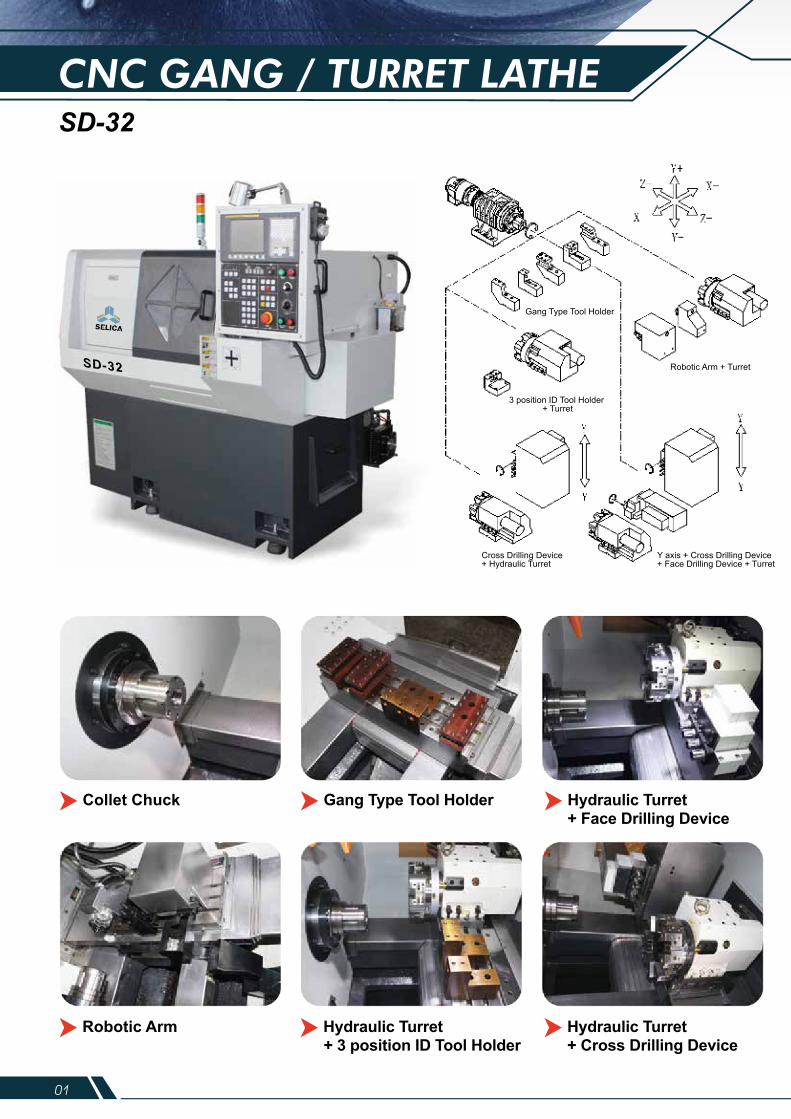
CNC GANG / TURRET LATHESD-32
500Ø100Ø3210020015
0.005Belt3.7
50-60004"
Ø250.75
80.3
---
0.750.750.75
1700
Linear guide way □16 Ø20 1/4
80(85%) 1
20(85%) 10
1850x1500x17001750
mm mm HP L
HP L
kva mm kg
Gang Type Tool Holder
3 position ID Tool Holder + Turret
Robotic Arm + Turret
Cross Drilling Device + Hydraulic Turret
Y axis + Cross Drilling Device+ Face Drilling Device + Turret
Collet Chuck Gang Type Tool Holder Hydraulic Turret+ Face Drilling Device
Robotic Arm Hydraulic Turret Hydraulic Turret+ Cross Drilling Device+ 3 position ID Tool Holder
Optional accessory
01 02
Max. swing over bedMax. turning diameterSpindle bore diameterMax. turning lengthX/Z-axis travelX/Z-axis rapid traversePositioning accuracyTransmissionSpindle motorSpindle speedSpindle chuckBallscrew diameterX/Z-axis motorNumber of tool stationTurret indexing timeFront drilling motorCross drilling motorY-axis motorSlideway typeTurning tool diameterBoring tool diameterCoolant motorCoolant tank capacityHydraulic motorHydraulic tank capacityPower requirementMachine dimensions(LxWxH)Weight
Model
Standard accessory
• Cutting coolant• Central lubrication unit• Tools and tool box• Foot switch• Operation manual• NC operation manual• NC maintenance manual• Collet chuck• Barfeeder interface• Inner tool holder• Wedge block• Cutting tool sleeve• Heat exchanger
• 4" 3 jaw chuck• Chip conveyor and cart• Parts conveyor• Parts catcher• Voltage stabilizer• Transformer• Hydraulic bar feeder
mm mm mm mm mm
m/min mm kw rpm
mm kw pcs sec kw kw kw
Unit SD-32 SD-32Y
CNC GANG / TURRET LATHESD-32
500Ø100Ø3210020015
0.005Belt3.7
50-60004"
Ø250.75
80.3
---
0.750.750.75
1700
Linear guide way □16 Ø20 1/4
80(85%) 1
20(85%) 10
1850x1500x17001750
mm mm HP L
HP L
kva mm kg
Gang Type Tool Holder
3 position ID Tool Holder + Turret
Robotic Arm + Turret
Cross Drilling Device + Hydraulic Turret
Y axis + Cross Drilling Device+ Face Drilling Device + Turret
Collet Chuck Gang Type Tool Holder Hydraulic Turret+ Face Drilling Device
Robotic Arm Hydraulic Turret Hydraulic Turret+ Cross Drilling Device+ 3 position ID Tool Holder
Optional accessory
03 04
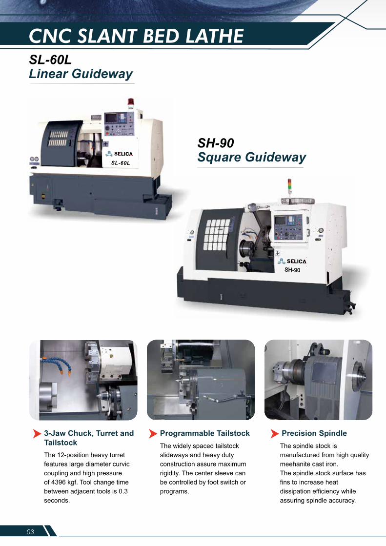
CNC SLANT BED LATHESL-60LLinear Guideway
SH-90Square Guideway
3-Jaw Chuck, Turret and TailstockThe 12-position heavy turret features large diameter curvic coupling and high pressureof 4396 kgf. Tool change time between adjacent tools is 0.3 seconds.
The widely spaced tailstock slideways and heavy dutyconstruction assure maximum rigidity. The center sleeve can be controlled by foot switch or programs.
The spindle stock is manufactured from high quality meehanite cast iron.The spindle stock surface has fins to increase heatdissipation efficiency while assuring spindle accuracy.
Programmable Tailstock Precision Spindle
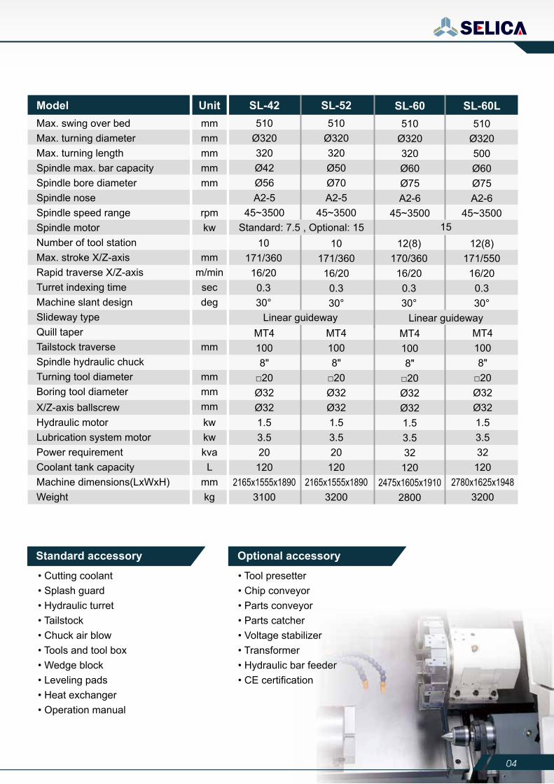
Model510
Ø320320Ø42Ø56A2-5
45~3500
510Ø320320Ø50Ø70A2-5
45~3500Standard: 7.5 , Optional: 15
Linear guideway
10171/360
16/200.330°
10171/360
16/200.330°
Unit SL-42 SL-52510
Ø320320Ø60Ø75A2-6
45~3500
510Ø320500Ø60Ø75A2-6
45~350015
Linear guideway
12(8)170/360
16/200.330°
12(8)171/55016/200.330°
SL-60 SL-60L
Standard accessory
• Cutting coolant• Splash guard• Hydraulic turret• Tailstock• Chuck air blow• Tools and tool box• Wedge block• Leveling pads• Heat exchanger• Operation manual
• Tool presetter• Chip conveyor• Parts conveyor• Parts catcher• Voltage stabilizer• Transformer• Hydraulic bar feeder• CE certification
Optional accessory
SL-60L
03 04
CNC SLANT BED LATHESL-60LLinear Guideway
SH-90Square Guideway
3-Jaw Chuck, Turret and TailstockThe 12-position heavy turret features large diameter curvic coupling and high pressureof 4396 kgf. Tool change time between adjacent tools is 0.3 seconds.
The widely spaced tailstock slideways and heavy dutyconstruction assure maximum rigidity. The center sleeve can be controlled by foot switch or programs.
The spindle stock is manufactured from high quality meehanite cast iron.The spindle stock surface has fins to increase heatdissipation efficiency while assuring spindle accuracy.
Programmable Tailstock Precision Spindle
Model510
Ø320320Ø42Ø56A2-5
45~3500
510Ø320320Ø50Ø70A2-5
45~3500Standard: 7.5 , Optional: 15
Linear guideway
10171/36016/200.330°
10171/36016/200.330°
Unit SL-42 SL-52510
Ø320320Ø60Ø75A2-6
45~3500
510Ø320500Ø60Ø75A2-6
45~350015
Linear guideway
12(8)170/36016/200.330°
12(8)171/55016/200.330°
SL-60 SL-60L
Standard accessory
• Cutting coolant• Splash guard• Hydraulic turret• Tailstock• Chuck air blow• Tools and tool box• Wedge block• Leveling pads• Heat exchanger• Operation manual
• Tool presetter• Chip conveyor• Parts conveyor• Parts catcher• Voltage stabilizer• Transformer• Hydraulic bar feeder• CE certification
Optional accessory
SL-60L
05 06
SH-900
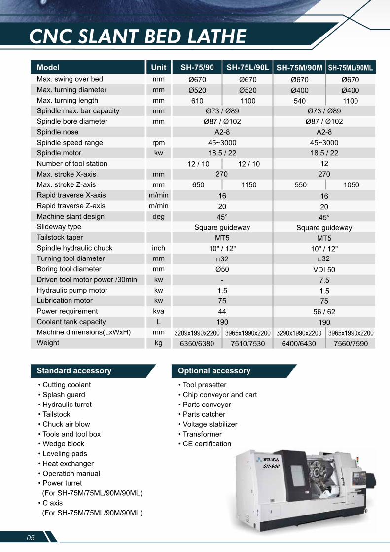
CNC SLANT BED LATHE
Max. swing over bedMax. turning diameterMax. turning lengthSpindle max. bar capacitySpindle bore diameterSpindle noseSpindle speed rangeSpindle motorNumber of tool stationMax. stroke X-axisMax. stroke Z-axisRapid traverse X-axisRapid traverse Z-axisMachine slant designSlideway typeTailstock taperSpindle hydraulic chuckTurning tool diameterBoring tool diameterDriven tool motor power /30minHydraulic pump motorLubrication motorPower requirementCoolant tank capacityMachine dimensions(LxWxH)Weight
Modelmm mm mm mm mm
rpmkw
mmmm
m/minm/mindeg
inchmmmmkwkwkwkvaL
mmkg
Ø670Ø520610
Ø670Ø5201100
3209x1990x22006350/6380
3965x1990x22007510/7530
Unit SH-75/90 SH-75L/90LØ670Ø400540
Ø670Ø4001100
650 1150270
12 / 10 12 / 10
550 1050
Ø73 / Ø89Ø87 / Ø102
A2-845~300018.5 / 22
12270
Ø73 / Ø89Ø87 / Ø102
A2-845~300018.5 / 22
162045°
Square guidewayMT5
10" / 12"□32Ø50
-1.57544
1903290x1990x2200
6400/64303965x1990x2200
7560/7590
SH-75M/90M SH-75ML/90ML
Standard accessory
• Cutting coolant• Splash guard• Hydraulic turret• Tailstock• Chuck air blow• Tools and tool box• Wedge block• Leveling pads• Heat exchanger• Operation manual• Power turret (For SH-75M/75ML/90M/90ML)• C axis (For SH-75M/75ML/90M/90ML)
• Tool presetter• Chip conveyor and cart• Parts conveyor• Parts catcher• Voltage stabilizer• Transformer• CE certification
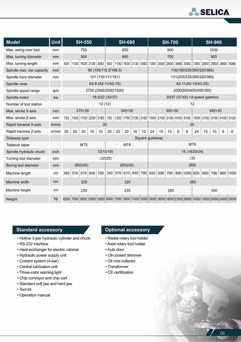
Optional accessory Standard accessory• Hollow 3-jaw hydraulic cylinder and chuck• RS-232 interface• Heat exchanger for electric cabinet• Hydraulic power supply unit• Coolant system (4-bar)• Central lubrication unit• Three-color warning light• Chip conveyor and chip cart• Standard soft jaw and hard jaw• Tool kit• Operation manual
• Radial rotary tool holder• Axial rotary tool holder• Auto door• Oil-coolant skimmer• Oil mist collector• Transformer• CE certification
Optional accessory
Max. swing over bed
Max. turning diameter
Max. turning length
Spindle max. bar capacity
Spindle bore diameter
Spindle nose
Spindle speed range
Spindle motor
Number of tool station
Max. stroke X-axis
Max. stroke Z-axis
Rapid traverse X-axis
Rapid traverse Z-axis
Slideway type
Tailstock taper
Spindle hydraulic chuck
Turning tool diameter
Boring tool diameter
Modelmm
mm
mm
mm
mm
rpm
kw
mm
mm
m/min
m/min
inch
mm
mm
750
550
850
680
Unit SH-550 SH-680900
700
1030
900
275+30 340+30 350+30 450+20
116(190/235/260/320/360)
131(205/235/260/320/380)
A2-11(A2-15/A2-20)
2000(800/600/400/300)
30/37 (37/45) +2-speed gearbox
12
90 (105/116.5/166.5)
101 (116/131/181)
A2-8 (A2-11/A2-15)
2700 (2500/2000/1500)
18.5/22 (30/37)
12 (12)
SH-700 SH-900
630 1130 1630 2130 3062
750 1250 1750 2250 3182
20 20 20 16 10 20 20 20 16 10
750 1250 1750 2130 3182
630 1130 1630 2130 3062 1300 2000 2900 3900 5000
1500 2100 3100 4100 5100
24 15 10 6 6 24 15 10 6 6
340 570 610 640 790 340 570 610 640 790 620 690 790 890 1050 620 690 790 890 1050
6200 7000 9000 10500 12000 6500 7500 9500 11000 12000 15000 16000 18000 23000 26000 16500 18500 20000 24000 25000
1500 2100 3100 4100 5120
1300 2000 2900 3900 5080
MT5 MT6
Ø50(40) Ø50(50)
230 235 260 300
220 220 280
Square guideway
20 20
Ø50
12(15/18)
□32(25)
Machine length
Machine width
Machine height
Weight
cm
cm
cm
kg
05 06
SH-900
CNC SLANT BED LATHE
Max. swing over bedMax. turning diameterMax. turning lengthSpindle max. bar capacitySpindle bore diameterSpindle noseSpindle speed rangeSpindle motorNumber of tool stationMax. stroke X-axisMax. stroke Z-axisRapid traverse X-axisRapid traverse Z-axisMachine slant designSlideway typeTailstock taperSpindle hydraulic chuckTurning tool diameterBoring tool diameterDriven tool motor power /30minHydraulic pump motorLubrication motorPower requirementCoolant tank capacityMachine dimensions(LxWxH)Weight
Modelmm mm mm mm mm
rpmkw
mmmm
m/minm/mindeg
inchmmmmkwkwkwkvaL
mmkg
Ø670Ø520610
Ø670Ø5201100
3209x1990x22006350/6380
3965x1990x22007510/7530
Unit SH-75/90 SH-75L/90LØ670Ø400540
Ø670Ø4001100
650 1150270
12 / 10 12 / 10
550 1050
Ø73 / Ø89Ø87 / Ø102
A2-845~300018.5 / 22
12270
Ø73 / Ø89Ø87 / Ø102
A2-845~300018.5 / 22
162045°
Square guidewayMT5
10" / 12"□32Ø50
-1.57544
1903290x1990x2200
6400/64303965x1990x2200
7560/7590
SH-75M/90M SH-75ML/90ML
Standard accessory
• Cutting coolant• Splash guard• Hydraulic turret• Tailstock• Chuck air blow• Tools and tool box• Wedge block• Leveling pads• Heat exchanger• Operation manual• Power turret (For SH-75M/75ML/90M/90ML)• C axis (For SH-75M/75ML/90M/90ML)
• Tool presetter• Chip conveyor and cart• Parts conveyor• Parts catcher• Voltage stabilizer• Transformer• CE certification
Optional accessory Standard accessory• Hollow 3-jaw hydraulic cylinder and chuck• RS-232 interface• Heat exchanger for electric cabinet• Hydraulic power supply unit• Coolant system (4-bar)• Central lubrication unit• Three-color warning light• Chip conveyor and chip cart• Standard soft jaw and hard jaw• Tool kit• Operation manual
• Radial rotary tool holder• Axial rotary tool holder• Auto door• Oil-coolant skimmer• Oil mist collector• Transformer• CE certification
Optional accessory
Max. swing over bed
Max. turning diameter
Max. turning length
Spindle max. bar capacity
Spindle bore diameter
Spindle nose
Spindle speed range
Spindle motor
Number of tool station
Max. stroke X-axis
Max. stroke Z-axis
Rapid traverse X-axis
Rapid traverse Z-axis
Slideway type
Tailstock taper
Spindle hydraulic chuck
Turning tool diameter
Boring tool diameter
Modelmm
mm
mm
mm
mm
rpm
kw
mm
mm
m/min
m/min
inch
mm
mm
750
550
850
680
Unit SH-550 SH-680900
700
1030
900
275+30 340+30 350+30 450+20
116(190/235/260/320/360)
131(205/235/260/320/380)
A2-11(A2-15/A2-20)
2000(800/600/400/300)
30/37 (37/45) +2-speed gearbox
12
90 (105/116.5/166.5)
101 (116/131/181)
A2-8 (A2-11/A2-15)
2700 (2500/2000/1500)
18.5/22 (30/37)
12 (12)
SH-700 SH-900
630 1130 1630 2130 3062
750 1250 1750 2250 3182
20 20 20 16 10 20 20 20 16 10
750 1250 1750 2130 3182
630 1130 1630 2130 3062 1300 2000 2900 3900 5000
1500 2100 3100 4100 5100
24 15 10 6 6 24 15 10 6 6
340 570 610 640 790 340 570 610 640 790 620 690 790 890 1050 620 690 790 890 1050
6200 7000 9000 10500 12000 6500 7500 9500 11000 12000 15000 16000 18000 23000 26000 16500 18500 20000 24000 25000
1500 2100 3100 4100 5120
1300 2000 2900 3900 5080
MT5 MT6
Ø50(40) Ø50(50)
230 235 260 300
220 220 280
Square guideway
20 20
Ø50
12(15/18)
□32(25)
Machine length
Machine width
Machine height
Weight
cm
cm
cm
kg
07 08
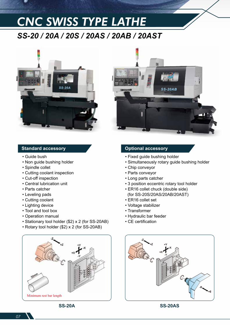
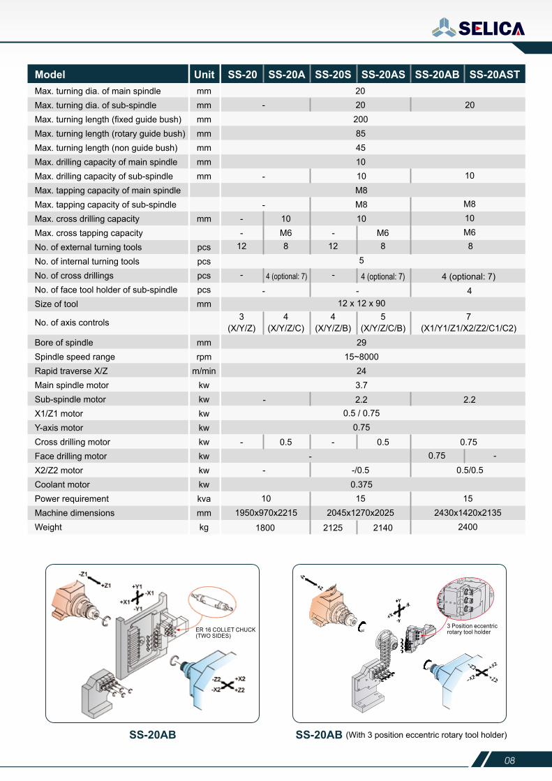
CNC SWISS TYPE LATHESS-20 / 20A / 20S / 20AS / 20AB / 20AST
Standard accessory
• Guide bush• Non guide bushing holder• Spindle collet• Cutting coolant inspection• Cut-off inspection• Central lubrication unit• Parts catcher• Leveling pads• Cutting coolant• Lighting device• Tool and tool box• Operation manual• Stationary tool holder ($2) x 2 (for SS-20AB)• Rotary tool holder ($2) x 2 (for SS-20AB)
• Fixed guide bushing holder• Simultaneously rotary guide bushing holder• Chip conveyor• Parts conveyor• Long parts catcher• 3 position eccentric rotary tool holder• ER16 collet chuck (double side) (for SS-20S/20AS/20AB/20AST)• ER16 collet set• Voltage stabilizer• Transformer• Hydraulic bar feeder• CE certification
Optional accessory
Minimum rest bar length
SS-20A SS-20AS SS-20AB SS-20AB
3 Position eccentric rotary tool holderER 16 COLLET CHUCK
(TWO SIDES)
(With 3 position eccentric rotary tool holder)
Max. turning dia. of main spindleMax. turning dia. of sub-spindleMax. turning length (fixed guide bush)Max. turning length (rotary guide bush)Max. turning length (non guide bush)Max. drilling capacity of main spindleMax. drilling capacity of sub-spindleMax. tapping capacity of main spindleMax. tapping capacity of sub-spindleMax. cross drilling capacity Max. cross tapping capacityNo. of external turning toolsNo. of internal turning toolsNo. of cross drillingsNo. of face tool holder of sub-spindleSize of tool
Bore of spindleSpindle speed rangeRapid traverse X/ZMain spindle motorSub-spindle motorX1/Z1 motorY-axis motorCross drilling motorFace drilling motorX2/Z2 motorCoolant motorPower requirementMachine dimensionsWeight
No. of axis controls
mmmmmmmmmmmmmm
mm
pcspcspcspcsmm
20- 20 20
-
-
10M8M810-
-10M6 - M6
8
4 (optional: 7)4 (optional: 7)
5
4 (optional: 7)
12 x 12 x 90
2915~8000
243.7
0.5 / 0.750.75
0.375
812 12
- -
8
10
M810M6
200854510
mmrpm
m/minkwkwkwkwkwkwkwkwkvammkg
Model Unit SS-20 SS-20A SS-20S SS-20AS SS-20AB SS-20AST
3(X/Y/Z)
4(X/Y/Z/C)
4(X/Y/Z/B)
5(X/Y/Z/C/B)
7(X1/Y1/Z1/X2/Z2/C1/C2)
- - 4
- 2.2 2.2
- 0.5-
- 0.50.75 -
0.75
- -/0.5 0.5/0.5
101950x970x2215
1800
152045x1270x2025
152430x1420x2135
24002125 2140
SS-20AB
07 08
CNC SWISS TYPE LATHESS-20 / 20A / 20S / 20AS / 20AB / 20AST
Standard accessory
• Guide bush• Non guide bushing holder• Spindle collet• Cutting coolant inspection• Cut-off inspection• Central lubrication unit• Parts catcher• Leveling pads• Cutting coolant• Lighting device• Tool and tool box• Operation manual• Stationary tool holder ($2) x 2 (for SS-20AB)• Rotary tool holder ($2) x 2 (for SS-20AB)
• Fixed guide bushing holder• Simultaneously rotary guide bushing holder• Chip conveyor• Parts conveyor• Long parts catcher• 3 position eccentric rotary tool holder• ER16 collet chuck (double side) (for SS-20S/20AS/20AB/20AST)• ER16 collet set• Voltage stabilizer• Transformer• Hydraulic bar feeder• CE certification
Optional accessory
Minimum rest bar length
SS-20A SS-20AS SS-20AB SS-20AB
3 Position eccentric rotary tool holderER 16 COLLET CHUCK
(TWO SIDES)
(With 3 position eccentric rotary tool holder)
Max. turning dia. of main spindleMax. turning dia. of sub-spindleMax. turning length (fixed guide bush)Max. turning length (rotary guide bush)Max. turning length (non guide bush)Max. drilling capacity of main spindleMax. drilling capacity of sub-spindleMax. tapping capacity of main spindleMax. tapping capacity of sub-spindleMax. cross drilling capacity Max. cross tapping capacityNo. of external turning toolsNo. of internal turning toolsNo. of cross drillingsNo. of face tool holder of sub-spindleSize of tool
Bore of spindleSpindle speed rangeRapid traverse X/ZMain spindle motorSub-spindle motorX1/Z1 motorY-axis motorCross drilling motorFace drilling motorX2/Z2 motorCoolant motorPower requirementMachine dimensionsWeight
No. of axis controls
mmmmmmmmmmmmmm
mm
pcspcspcspcsmm
20- 20 20
-
-
10M8M810-
-10M6 - M6
8
4 (optional: 7)4 (optional: 7)
5
4 (optional: 7)
12 x 12 x 90
2915~8000
243.7
0.5 / 0.750.75
0.375
812 12
- -
8
10
M810M6
200854510
mmrpm
m/minkwkwkwkwkwkwkwkwkvammkg
Model Unit SS-20 SS-20A SS-20S SS-20AS SS-20AB SS-20AST
3(X/Y/Z)
4(X/Y/Z/C)
4(X/Y/Z/B)
5(X/Y/Z/C/B)
7(X1/Y1/Z1/X2/Z2/C1/C2)
- - 4
- 2.2 2.2
- 0.5-
- 0.50.75 -
0.75
- -/0.5 0.5/0.5
101950x970x2215
1800
152045x1270x2025
152430x1420x2135
24002125 2140
SS-20AB
09 10
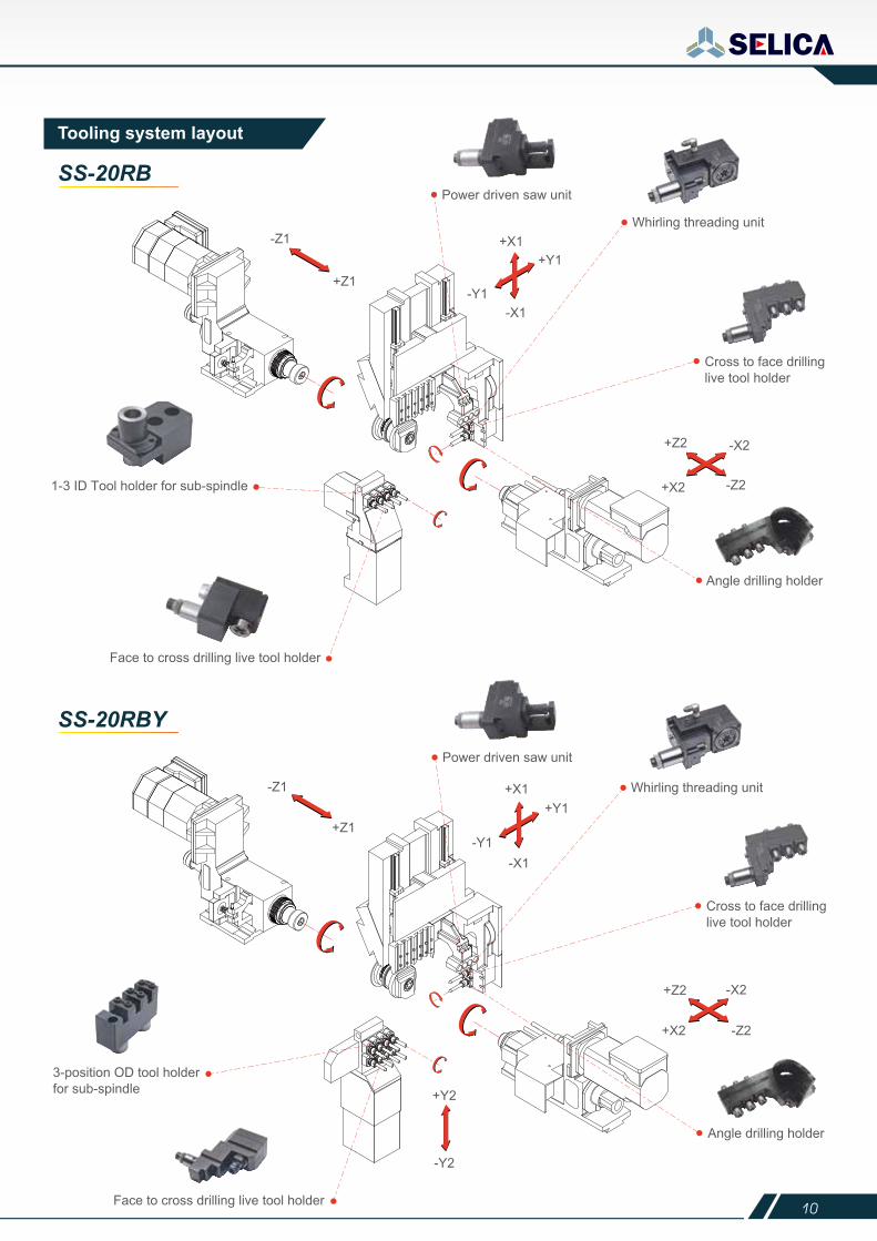
Tooling system layout
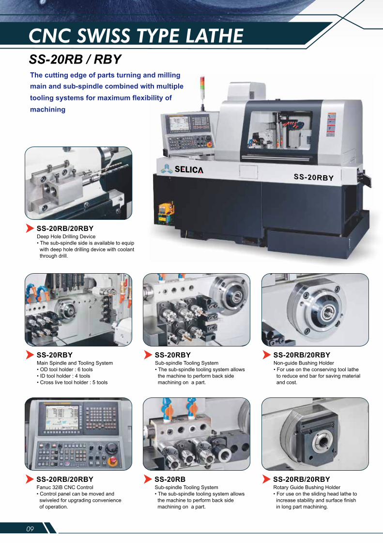
CNC SWISS TYPE LATHESS-20RB / RBY
SS-20RB
SS-20RBY
Main Spindle and Tooling System• OD tool holder : 6 tools• ID tool holder : 4 tools• Cross live tool holder : 5 tools
SS-20RBY
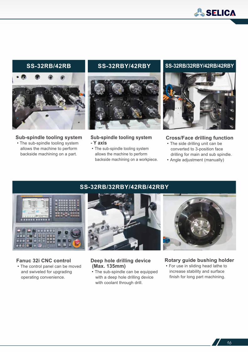
Deep Hole Drilling Device• The sub-spindle side is available to equip with deep hole drilling device with coolant through drill.
SS-20RB/20RBY
Sub-spindle Tooling System• The sub-spindle tooling system allows the machine to perform back side machining on a part.
SS-20RBYNon-guide Bushing Holder• For use on the conserving tool lathe to reduce end bar for saving material and cost.
SS-20RB/20RBY
Fanuc 32iB CNC Control• Control panel can be moved and swiveled for upgrading convenience of operation.
SS-20RB/20RBYSub-spindle Tooling System• The sub-spindle tooling system allows the machine to perform back side machining on a part.
SS-20RBRotary Guide Bushing Holder• For use on the sliding head lathe to increase stability and surface finish in long part machining.
SS-20RB/20RBY
The cutting edge of parts turning and millingmain and sub-spindle combined with multiple tooling systems for maximum flexibility of machining
09 10
Tooling system layout
CNC SWISS TYPE LATHESS-20RB / RBY
SS-20RB
SS-20RBY
Main Spindle and Tooling System• OD tool holder : 6 tools• ID tool holder : 4 tools• Cross live tool holder : 5 tools
SS-20RBY
Deep Hole Drilling Device• The sub-spindle side is available to equip with deep hole drilling device with coolant through drill.
SS-20RB/20RBY
Sub-spindle Tooling System• The sub-spindle tooling system allows the machine to perform back side machining on a part.
SS-20RBYNon-guide Bushing Holder• For use on the conserving tool lathe to reduce end bar for saving material and cost.
SS-20RB/20RBY
Fanuc 32iB CNC Control• Control panel can be moved and swiveled for upgrading convenience of operation.
SS-20RB/20RBYSub-spindle Tooling System• The sub-spindle tooling system allows the machine to perform back side machining on a part.
SS-20RBRotary Guide Bushing Holder• For use on the sliding head lathe to increase stability and surface finish in long part machining.
SS-20RB/20RBY
The cutting edge of parts turning and millingmain and sub-spindle combined with multiple tooling systems for maximum flexibility of machining
11 12
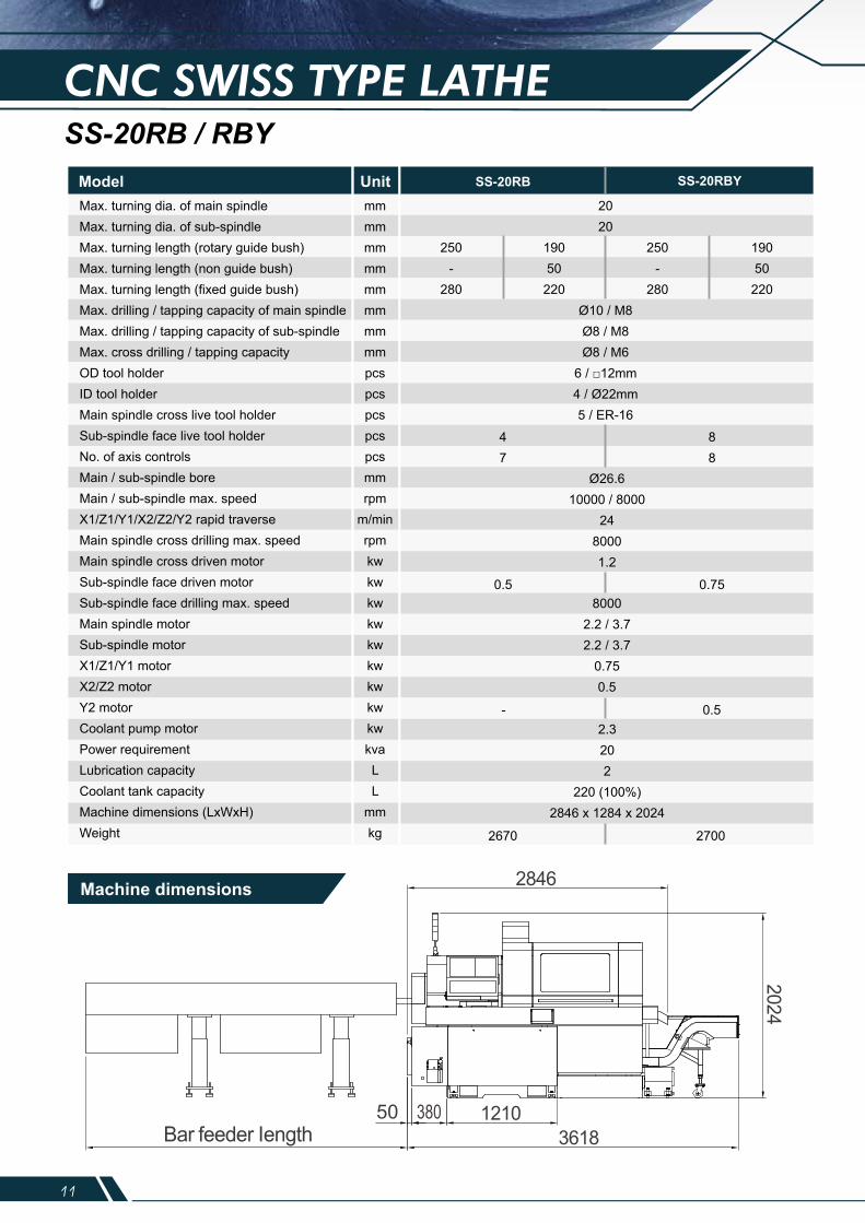
CNC SWISS TYPE LATHESS-20RB / RBY
Max. turning dia. of main spindleMax. turning dia. of sub-spindleMax. turning length (rotary guide bush)Max. turning length (non guide bush)Max. turning length (fixed guide bush)Max. drilling / tapping capacity of main spindleMax. drilling / tapping capacity of sub-spindleMax. cross drilling / tapping capacityOD tool holderID tool holderMain spindle cross live tool holderSub-spindle face live tool holderNo. of axis controlsMain / sub-spindle boreMain / sub-spindle max. speedX1/Z1/Y1/X2/Z2/Y2 rapid traverseMain spindle cross drilling max. speedMain spindle cross driven motorSub-spindle face driven motorSub-spindle face drilling max. speedMain spindle motorSub-spindle motorX1/Z1/Y1 motorX2/Z2 motorY2 motorCoolant pump motorPower requirementLubrication capacityCoolant tank capacityMachine dimensions (LxWxH)Weight
mmmmmmmmmmmmmmmmpcspcspcspcspcsmmrpm
m/minrpmkwkwkwkwkwkwkwkwkwkvaLL
mmkg
Model Unit
Ø10 / M8Ø8 / M8Ø8 / M6
6 / □12mm4 / Ø22mm5 / ER-16
2020
SS-20RB SS-20RBY
47
250-
280
19050
220
250-
280
19050220
88
0.5 0.75
Ø26.610000 / 8000
2480001.2
80002.2 / 3.72.2 / 3.7
0.750.5
2.3202
220 (100%)2846 x 1284 x 2024
- 0.5
2670 2700
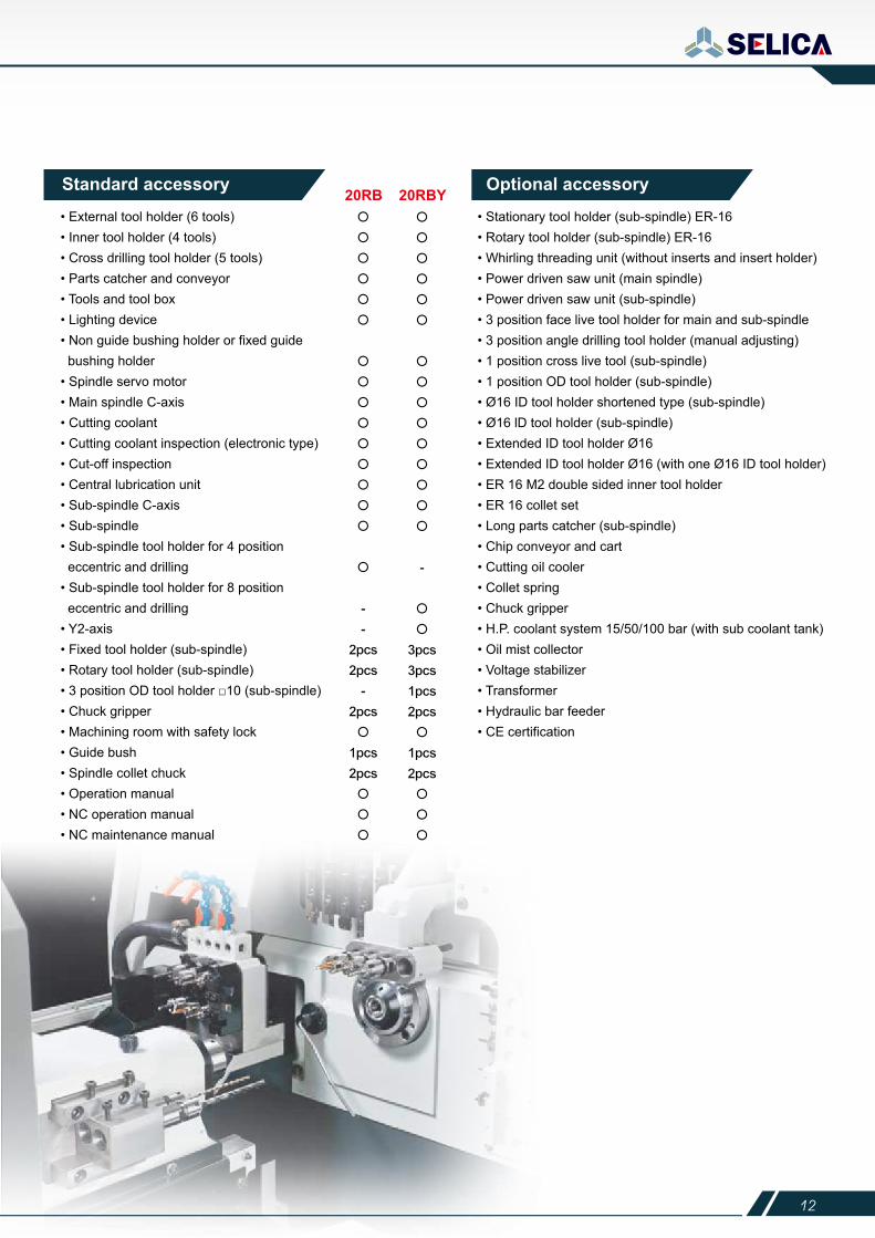
• External tool holder (6 tools) • Inner tool holder (4 tools) • Cross drilling tool holder (5 tools) • Parts catcher and conveyor • Tools and tool box • Lighting device • Non guide bushing holder or fixed guide bushing holder • Spindle servo motor • Main spindle C-axis • Cutting coolant • Cutting coolant inspection (electronic type) • Cut-off inspection • Central lubrication unit • Sub-spindle C-axis • Sub-spindle • Sub-spindle tool holder for 4 position eccentric and drilling• Sub-spindle tool holder for 8 position eccentric and drilling • Y2-axis • Fixed tool holder (sub-spindle) • Rotary tool holder (sub-spindle)• 3 position OD tool holder □10 (sub-spindle) • Chuck gripper • Machining room with safety lock • Guide bush • Spindle collet chuck • Operation manual • NC operation manual • NC maintenance manual
20RB 20RBY• Stationary tool holder (sub-spindle) ER-16• Rotary tool holder (sub-spindle) ER-16• Whirling threading unit (without inserts and insert holder)• Power driven saw unit (main spindle)• Power driven saw unit (sub-spindle)• 3 position face live tool holder for main and sub-spindle• 3 position angle drilling tool holder (manual adjusting)• 1 position cross live tool (sub-spindle)• 1 position OD tool holder (sub-spindle)• Ø16 ID tool holder shortened type (sub-spindle)• Ø16 lD tool holder (sub-spindle)• Extended ID tool holder Ø16• Extended ID tool holder Ø16 (with one Ø16 ID tool holder)• ER 16 M2 double sided inner tool holder• ER 16 collet set• Long parts catcher (sub-spindle)• Chip conveyor and cart• Cutting oil cooler• Collet spring• Chuck gripper• H.P. coolant system 15/50/100 bar (with sub coolant tank)• Oil mist collector• Voltage stabilizer• Transformer• Hydraulic bar feeder• CE certification
Standard accessory Optional accessory
○
○
○
○
○
○
○
○
○
○
○
○
○
○
○
○
○
○
○
○
○
○
○
○
○
○
○
○
○
○
○
○
○
○
○
○
○
○
○
○
○
50 380
Machine dimensions
11 12
CNC SWISS TYPE LATHESS-20RB / RBY
Max. turning dia. of main spindleMax. turning dia. of sub-spindleMax. turning length (rotary guide bush)Max. turning length (non guide bush)Max. turning length (fixed guide bush)Max. drilling / tapping capacity of main spindleMax. drilling / tapping capacity of sub-spindleMax. cross drilling / tapping capacityOD tool holderID tool holderMain spindle cross live tool holderSub-spindle face live tool holderNo. of axis controlsMain / sub-spindle boreMain / sub-spindle max. speedX1/Z1/Y1/X2/Z2/Y2 rapid traverseMain spindle cross drilling max. speedMain spindle cross driven motorSub-spindle face driven motorSub-spindle face drilling max. speedMain spindle motorSub-spindle motorX1/Z1/Y1 motorX2/Z2 motorY2 motorCoolant pump motorPower requirementLubrication capacityCoolant tank capacityMachine dimensions (LxWxH)Weight
mmmmmmmmmmmmmmmmpcspcspcspcspcsmmrpm
m/minrpmkwkwkwkwkwkwkwkwkwkvaLL
mmkg
Model Unit
Ø10 / M8Ø8 / M8Ø8 / M6
6 / □12mm4 / Ø22mm5 / ER-16
2020
SS-20RB SS-20RBY
47
250-
280
19050
220
250-
280
19050
220
88
0.5 0.75
Ø26.610000 / 8000
2480001.2
80002.2 / 3.72.2 / 3.7
0.750.5
2.3202
220 (100%)2846 x 1284 x 2024
- 0.5
2670 2700
• External tool holder (6 tools) • Inner tool holder (4 tools) • Cross drilling tool holder (5 tools) • Parts catcher and conveyor • Tools and tool box • Lighting device • Non guide bushing holder or fixed guide bushing holder • Spindle servo motor • Main spindle C-axis • Cutting coolant • Cutting coolant inspection (electronic type) • Cut-off inspection • Central lubrication unit • Sub-spindle C-axis • Sub-spindle • Sub-spindle tool holder for 4 position eccentric and drilling• Sub-spindle tool holder for 8 position eccentric and drilling • Y2-axis • Fixed tool holder (sub-spindle) • Rotary tool holder (sub-spindle)• 3 position OD tool holder □10 (sub-spindle) • Chuck gripper • Machining room with safety lock • Guide bush • Spindle collet chuck • Operation manual • NC operation manual • NC maintenance manual
20RB 20RBY• Stationary tool holder (sub-spindle) ER-16• Rotary tool holder (sub-spindle) ER-16• Whirling threading unit (without inserts and insert holder)• Power driven saw unit (main spindle)• Power driven saw unit (sub-spindle)• 3 position face live tool holder for main and sub-spindle• 3 position angle drilling tool holder (manual adjusting)• 1 position cross live tool (sub-spindle)• 1 position OD tool holder (sub-spindle)• Ø16 ID tool holder shortened type (sub-spindle)• Ø16 lD tool holder (sub-spindle)• Extended ID tool holder Ø16• Extended ID tool holder Ø16 (with one Ø16 ID tool holder)• ER 16 M2 double sided inner tool holder• ER 16 collet set• Long parts catcher (sub-spindle)• Chip conveyor and cart• Cutting oil cooler• Collet spring• Chuck gripper• H.P. coolant system 15/50/100 bar (with sub coolant tank)• Oil mist collector• Voltage stabilizer• Transformer• Hydraulic bar feeder• CE certification
Standard accessory Optional accessory
○
○
○
○
○
○
○
○
○
○
○
○
○
○
○
○
○
○
○
○
○
○
○
○
○
○
○
○
○
○
○
○
○
○
○
○
○
○
○
○
○
50 380
Machine dimensions
13 14
SS-32AB
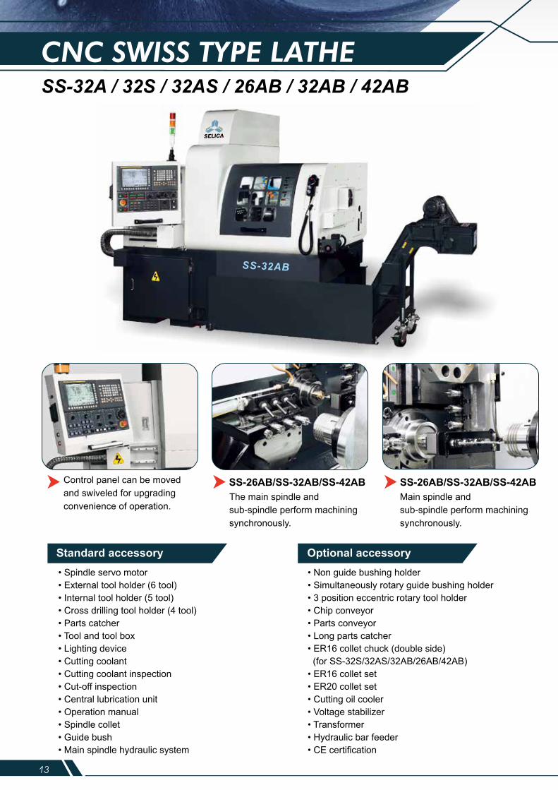
CNC SWISS TYPE LATHESS-32A / 32S / 32AS / 26AB / 32AB / 42AB
Max. turning dia. of main spindleMax. turning dia. of sub-spindleMax. turning length (fixed guide bush)Max. turning length (rotary guide bush)Max. turning length (non guide bush)Max. drilling capacity of main spindleMax. drilling capacity of sub-spindleMax. tapping capacity of main spindleMax. tapping capacity of sub-spindleMax. cross drilling capacityMax. cross tapping capacityNo. of external turning toolsNo. of internal turning toolsNo. of cross drillingsNo. of face tool holder of sub-spindleSize of toolNo. of axis controlsBore of spindleSpindle speed rangeRapid traverse X / ZMain spindle motorSub-spindle motorX1 / Z1 motorY-axis motorCross drilling motorFace drilling motorX2 / Z2 motorCoolant pump motorMachine dimensionsWeight
mmmmmmmmmmmmmm
mm
pcspcspcspcsmm
mmrpm
m/minkwkwkwkwkwkwkwkwmmkg
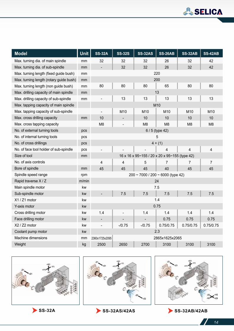
Model Unit SS-32A SS-32S SS-32AS SS-26AB SS-32AB SS-42AB
1.4--
--
-/0.75
1.4-
-/0.75
1.40.75
0.75/0.75
1.40.75
0.75/0.75
1.40.75
0.75/0.75
25002360x1725x2095 2865x1625x2065
2650 2700 3100 3100 3100
32-
3232
3232
2626
3232
4242
220200
13
M10
16 x 16 x 95~155 / 20 x 20 x 95~155 (type 42)
6 / 5 (type 42)5
4 + (1)
247.5
1.40.75
2.3
80 80 80 65 80 80
- 13 13 13 13 13
-10M8
M10--
M1010M8
M1010M8
M1010M8
M1010M8
- 7.5 7.5 7.5 7.5 7.5
- - - 4 4 4
200 ~ 7000 / 200 ~ 6000 (type 42)
445
445
545
740
745
745
SS-32A SS-32AS/42AS SS-32AB/42AB
Control panel can be moved and swiveled for upgrading convenience of operation.
The main spindle and sub-spindle perform machining synchronously.
Main spindle andsub-spindle perform machining synchronously.
SS-26AB/SS-32AB/SS-42AB SS-26AB/SS-32AB/SS-42AB
Standard accessory• Spindle servo motor• External tool holder (6 tool)• Internal tool holder (5 tool)• Cross drilling tool holder (4 tool)• Parts catcher• Tool and tool box• Lighting device• Cutting coolant• Cutting coolant inspection• Cut-off inspection• Central lubrication unit• Operation manual• Spindle collet• Guide bush• Main spindle hydraulic system
• Non guide bushing holder• Simultaneously rotary guide bushing holder• 3 position eccentric rotary tool holder• Chip conveyor• Parts conveyor• Long parts catcher• ER16 collet chuck (double side) (for SS-32S/32AS/32AB/26AB/42AB)• ER16 collet set• ER20 collet set• Cutting oil cooler• Voltage stabilizer• Transformer• Hydraulic bar feeder• CE certification
Optional accessory
13 14
SS-32AB
CNC SWISS TYPE LATHESS-32A / 32S / 32AS / 26AB / 32AB / 42AB
Max. turning dia. of main spindleMax. turning dia. of sub-spindleMax. turning length (fixed guide bush)Max. turning length (rotary guide bush)Max. turning length (non guide bush)Max. drilling capacity of main spindleMax. drilling capacity of sub-spindleMax. tapping capacity of main spindleMax. tapping capacity of sub-spindleMax. cross drilling capacityMax. cross tapping capacityNo. of external turning toolsNo. of internal turning toolsNo. of cross drillingsNo. of face tool holder of sub-spindleSize of toolNo. of axis controlsBore of spindleSpindle speed rangeRapid traverse X / ZMain spindle motorSub-spindle motorX1 / Z1 motorY-axis motorCross drilling motorFace drilling motorX2 / Z2 motorCoolant pump motorMachine dimensionsWeight
mmmmmmmmmmmmmm
mm
pcspcspcspcsmm
mmrpm
m/minkwkwkwkwkwkwkwkwmmkg
Model Unit SS-32A SS-32S SS-32AS SS-26AB SS-32AB SS-42AB
1.4--
--
-/0.75
1.4-
-/0.75
1.40.75
0.75/0.75
1.40.75
0.75/0.75
1.40.75
0.75/0.75
25002360x1725x2095 2865x1625x2065
2650 2700 3100 3100 3100
32-
3232
3232
2626
3232
4242
220200
13
M10
16 x 16 x 95~155 / 20 x 20 x 95~155 (type 42)
6 / 5 (type 42)5
4 + (1)
247.5
1.40.75
2.3
80 80 80 65 80 80
- 13 13 13 13 13
-10M8
M10--
M1010M8
M1010M8
M1010M8
M1010M8
- 7.5 7.5 7.5 7.5 7.5
- - - 4 4 4
200 ~ 7000 / 200 ~ 6000 (type 42)
445
445
545
740
745
745
SS-32A SS-32AS/42AS SS-32AB/42AB
Control panel can be moved and swiveled for upgrading convenience of operation.
The main spindle and sub-spindle perform machining synchronously.
Main spindle andsub-spindle perform machining synchronously.
SS-26AB/SS-32AB/SS-42AB SS-26AB/SS-32AB/SS-42AB
Standard accessory• Spindle servo motor• External tool holder (6 tool)• Internal tool holder (5 tool)• Cross drilling tool holder (4 tool)• Parts catcher• Tool and tool box• Lighting device• Cutting coolant• Cutting coolant inspection• Cut-off inspection• Central lubrication unit• Operation manual• Spindle collet• Guide bush• Main spindle hydraulic system
• Non guide bushing holder• Simultaneously rotary guide bushing holder• 3 position eccentric rotary tool holder• Chip conveyor• Parts conveyor• Long parts catcher• ER16 collet chuck (double side) (for SS-32S/32AS/32AB/26AB/42AB)• ER16 collet set• ER20 collet set• Cutting oil cooler• Voltage stabilizer• Transformer• Hydraulic bar feeder• CE certification
Optional accessory
15 16
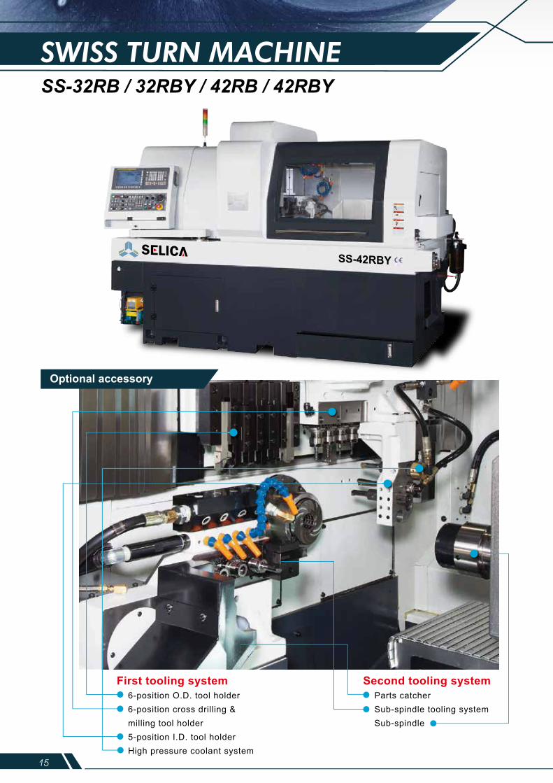
SWISS TURN MACHINESS-32RB / 32RBY / 42RB / 42RBY
Optional accessory
SS-32RB/42RB SS-32RBY/42RBY SS-32RB/32RBY/42RB/42RBY
SS-32RB/32RBY/42RB/42RBY
15 16
SWISS TURN MACHINESS-32RB / 32RBY / 42RB / 42RBY
Optional accessory
SS-32RB/42RB SS-32RBY/42RBY SS-32RB/32RBY/42RB/42RBY
SS-32RB/32RBY/42RB/42RBY
17 18
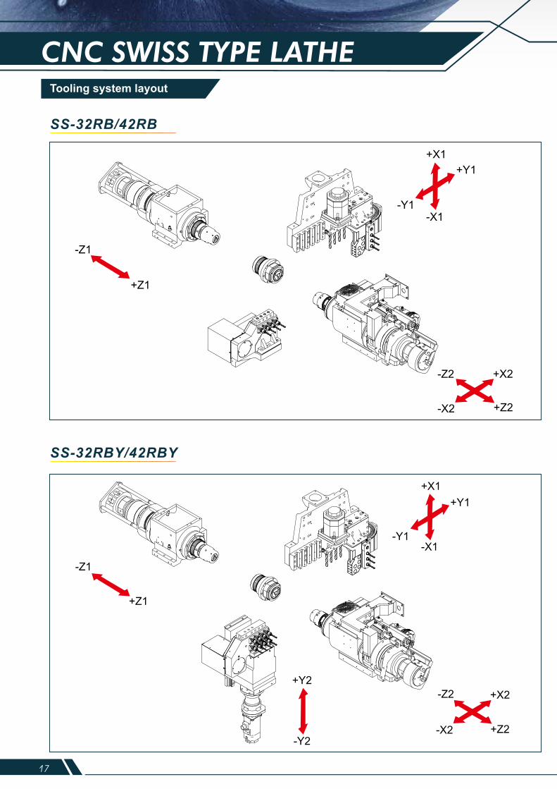
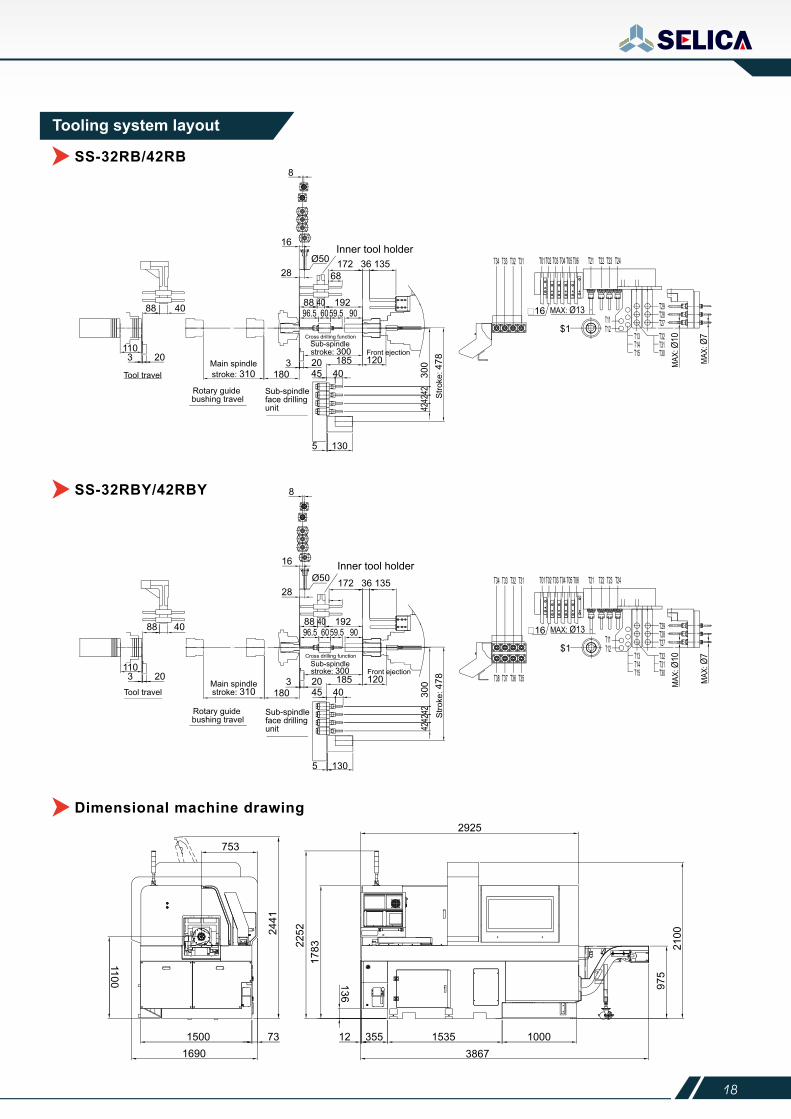
Tooling system layout Tooling system layout
CNC SWISS TYPE LATHE
SS-32RB/42RB
SS-32RBY/42RBY
SS-32RB/42RB
SS-32RBY/42RBY
Dimensional machine drawing
Inner tool holder
Cross drilling function
Inner tool holder
Cross drilling function
17 18
Tooling system layout Tooling system layout
CNC SWISS TYPE LATHE
SS-32RB/42RB
SS-32RBY/42RBY
SS-32RB/42RB
SS-32RBY/42RBY
Dimensional machine drawing
Inner tool holder
Cross drilling function
Inner tool holder
Cross drilling function
19 20
CNC SWISS TYPE LATHE
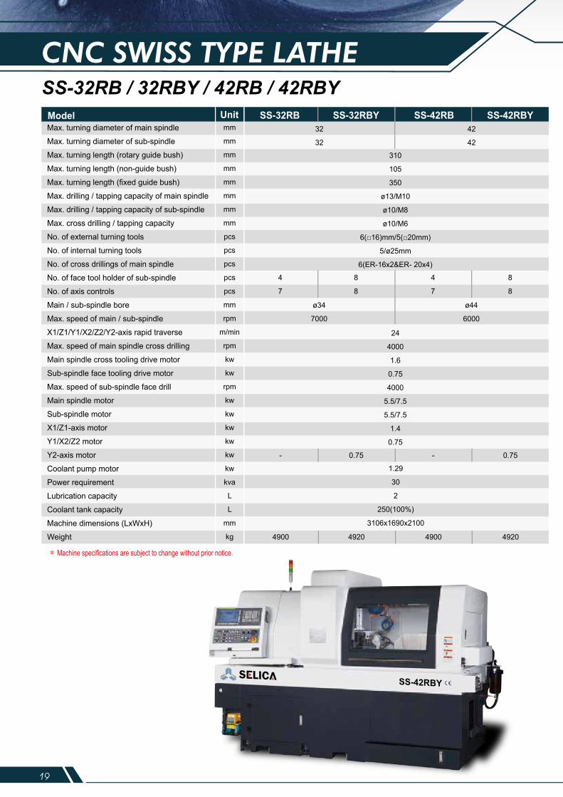
SS-32RB SS-32RBY SS-42RB SS-42RBY
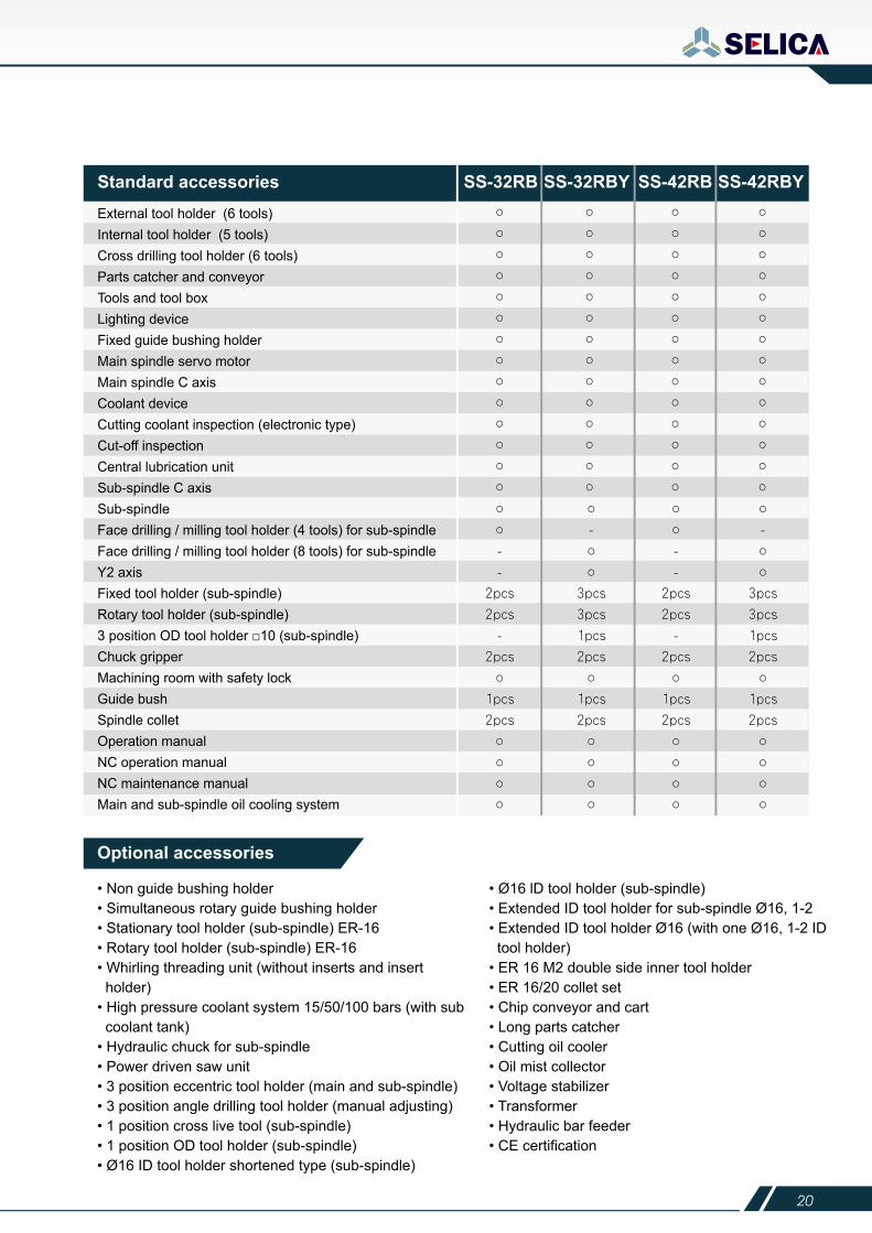
Optional accessories
SS-32RB / 32RBY / 42RB / 42RBYSS-32RBStandard accessories SS-32RBY SS-42RB SS-42RBY
External tool holder (6 tools)Internal tool holder (5 tools)Cross drilling tool holder (6 tools)Parts catcher and conveyorTools and tool boxLighting deviceFixed guide bushing holder Main spindle servo motorMain spindle C axisCoolant deviceCutting coolant inspection (electronic type)Cut-off inspectionCentral lubrication unitSub-spindle C axisSub-spindleFace drilling / milling tool holder (4 tools) for sub-spindleFace drilling / milling tool holder (8 tools) for sub-spindleY2 axisFixed tool holder (sub-spindle) Rotary tool holder (sub-spindle) 3 position OD tool holder □10 (sub-spindle) Chuck gripperMachining room with safety lockGuide bushSpindle colletOperation manualNC operation manualNC maintenance manualMain and sub-spindle oil cooling system
• Non guide bushing holder• Simultaneous rotary guide bushing holder• Stationary tool holder (sub-spindle) ER-16• Rotary tool holder (sub-spindle) ER-16• Whirling threading unit (without inserts and insert holder)• High pressure coolant system 15/50/100 bars (with sub coolant tank)• Hydraulic chuck for sub-spindle• Power driven saw unit• 3 position eccentric tool holder (main and sub-spindle)• 3 position angle drilling tool holder (manual adjusting)• 1 position cross live tool (sub-spindle)• 1 position OD tool holder (sub-spindle)• Ø16 ID tool holder shortened type (sub-spindle)
• Ø16 lD tool holder (sub-spindle)• Extended ID tool holder for sub-spindle Ø16, 1-2• Extended ID tool holder Ø16 (with one Ø16, 1-2 ID tool holder)• ER 16 M2 double side inner tool holder• ER 16/20 collet set• Chip conveyor and cart• Long parts catcher• Cutting oil cooler• Oil mist collector• Voltage stabilizer• Transformer• Hydraulic bar feeder• CE certification
Max. turning diameter of main spindle
Max. turning diameter of sub-spindle
Max. turning length (rotary guide bush)
Max. turning length (non-guide bush)
Max. turning length (fixed guide bush)
Max. drilling / tapping capacity of main spindle
Max. drilling / tapping capacity of sub-spindle
Max. cross drilling / tapping capacity
No. of external turning tools
No. of internal turning tools
No. of cross drillings of main spindle
No. of face tool holder of sub-spindle
No. of axis controls
Main / sub-spindle bore
Max. speed of main / sub-spindle
X1/Z1/Y1/X2/Z2/Y2-axis rapid traverse
Max. speed of main spindle cross drilling
Main spindle cross tooling drive motor
Sub-spindle face tooling drive motor
Max. speed of sub-spindle face drill
Main spindle motor
Sub-spindle motor
X1/Z1-axis motor
Y1/X2/Z2 motor
Y2-axis motor
Coolant pump motor
Power requirement
Lubrication capacity
Coolant tank capacity
Machine dimensions (LxWxH)
Weight
mm
mm
mm
mm
mm
mm
mm
mm
pcs
pcs
pcs
pcs
pcs
mm
rpm
m/min
rpm
kw
kw
rpm
kw
kw
kw
kw
kw
kw
kva
L
L
mm
kg
32
32
4
7
8
8
4
7
8
8
310
105
350
ø13/M10
ø10/M8
ø10/M6
6(□16)mm/5(□20mm)
5/ø25mm
6(ER-16x2&ER- 20x4)
24
4000
1.6
0.75
4000
5.5/7.5
5.5/7.5
1.4
0.75
1.29
30
2
250(100%)
3106x1690x2100
42
42
ø34
7000
ø44
6000
- 0.75 - 0.75
4900 4920 4900 4920
Model Unit
19 20
CNC SWISS TYPE LATHE
SS-32RB SS-32RBY SS-42RB SS-42RBY
Optional accessories
SS-32RB / 32RBY / 42RB / 42RBYSS-32RBStandard accessories SS-32RBY SS-42RB SS-42RBY
External tool holder (6 tools)Internal tool holder (5 tools)Cross drilling tool holder (6 tools)Parts catcher and conveyorTools and tool boxLighting deviceFixed guide bushing holder Main spindle servo motorMain spindle C axisCoolant deviceCutting coolant inspection (electronic type)Cut-off inspectionCentral lubrication unitSub-spindle C axisSub-spindleFace drilling / milling tool holder (4 tools) for sub-spindleFace drilling / milling tool holder (8 tools) for sub-spindleY2 axisFixed tool holder (sub-spindle) Rotary tool holder (sub-spindle) 3 position OD tool holder □10 (sub-spindle) Chuck gripperMachining room with safety lockGuide bushSpindle colletOperation manualNC operation manualNC maintenance manualMain and sub-spindle oil cooling system
• Non guide bushing holder• Simultaneous rotary guide bushing holder• Stationary tool holder (sub-spindle) ER-16• Rotary tool holder (sub-spindle) ER-16• Whirling threading unit (without inserts and insert holder)• High pressure coolant system 15/50/100 bars (with sub coolant tank)• Hydraulic chuck for sub-spindle• Power driven saw unit• 3 position eccentric tool holder (main and sub-spindle)• 3 position angle drilling tool holder (manual adjusting)• 1 position cross live tool (sub-spindle)• 1 position OD tool holder (sub-spindle)• Ø16 ID tool holder shortened type (sub-spindle)
• Ø16 lD tool holder (sub-spindle)• Extended ID tool holder for sub-spindle Ø16, 1-2• Extended ID tool holder Ø16 (with one Ø16, 1-2 ID tool holder)• ER 16 M2 double side inner tool holder• ER 16/20 collet set• Chip conveyor and cart• Long parts catcher• Cutting oil cooler• Oil mist collector• Voltage stabilizer• Transformer• Hydraulic bar feeder• CE certification
Max. turning diameter of main spindle
Max. turning diameter of sub-spindle
Max. turning length (rotary guide bush)
Max. turning length (non-guide bush)
Max. turning length (fixed guide bush)
Max. drilling / tapping capacity of main spindle
Max. drilling / tapping capacity of sub-spindle
Max. cross drilling / tapping capacity
No. of external turning tools
No. of internal turning tools
No. of cross drillings of main spindle
No. of face tool holder of sub-spindle
No. of axis controls
Main / sub-spindle bore
Max. speed of main / sub-spindle
X1/Z1/Y1/X2/Z2/Y2-axis rapid traverse
Max. speed of main spindle cross drilling
Main spindle cross tooling drive motor
Sub-spindle face tooling drive motor
Max. speed of sub-spindle face drill
Main spindle motor
Sub-spindle motor
X1/Z1-axis motor
Y1/X2/Z2 motor
Y2-axis motor
Coolant pump motor
Power requirement
Lubrication capacity
Coolant tank capacity
Machine dimensions (LxWxH)
Weight
mm
mm
mm
mm
mm
mm
mm
mm
pcs
pcs
pcs
pcs
pcs
mm
rpm
m/min
rpm
kw
kw
rpm
kw
kw
kw
kw
kw
kw
kva
L
L
mm
kg
32
32
4
7
8
8
4
7
8
8
310
105
350
ø13/M10
ø10/M8
ø10/M6
6(□16)mm/5(□20mm)
5/ø25mm
6(ER-16x2&ER- 20x4)
24
4000
1.6
0.75
4000
5.5/7.5
5.5/7.5
1.4
0.75
1.29
30
2
250(100%)
3106x1690x2100
42
42
ø34
7000
ø44
6000
- 0.75 - 0.75
4900 4920 4900 4920
Model Unit
21 22
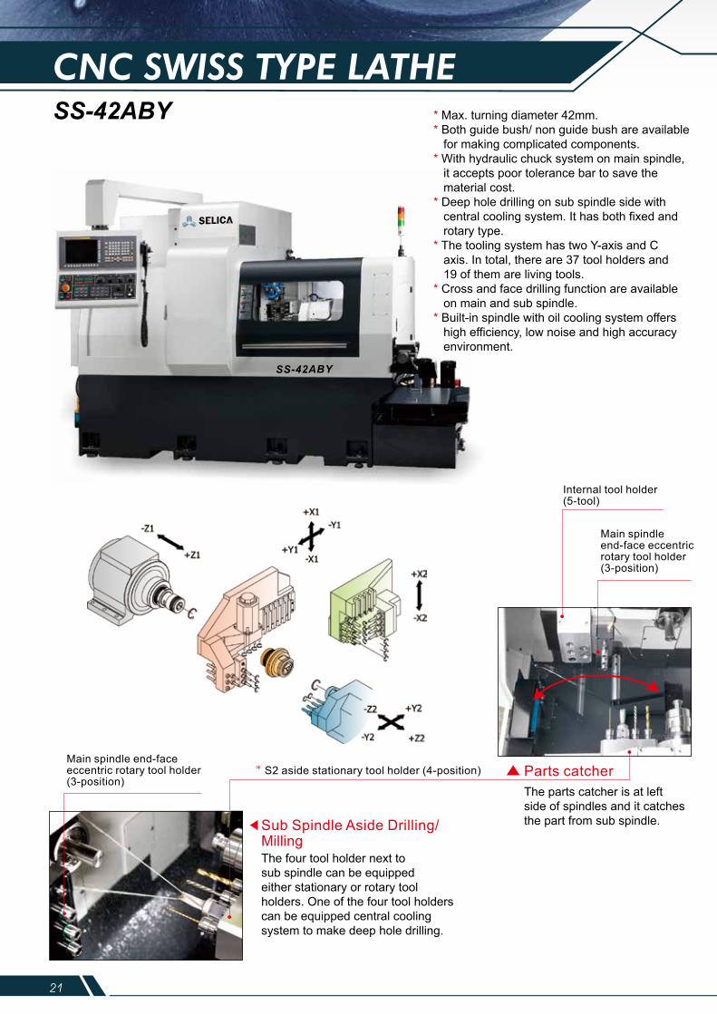
CNC SWISS TYPE LATHESS-42ABY * Max. turning diameter 42mm.
* Both guide bush/ non guide bush are available for making complicated components.* With hydraulic chuck system on main spindle, it accepts poor tolerance bar to save the material cost.* Deep hole drilling on sub spindle side with central cooling system. It has both fixed and rotary type.* The tooling system has two Y-axis and C axis. In total, there are 37 tool holders and 19 of them are living tools.* Cross and face drilling function are available on main and sub spindle.* Built-in spindle with oil cooling system offers high efficiency, low noise and high accuracy environment.
Sub Spindle Aside Drilling/ Milling
Parts catcherMain spindle end-faceeccentric rotary tool holder(3-position)
* S2 aside stationary tool holder (4-position)
Main spindle end-face eccentric rotary tool holder(3-position)
Internal tool holder(5-tool)
The four tool holder next to sub spindle can be equipped either stationary or rotary toolholders. One of the four tool holders can be equipped central cooling system to make deep hole drilling.
The parts catcher is at left side of spindles and it catches the part from sub spindle.
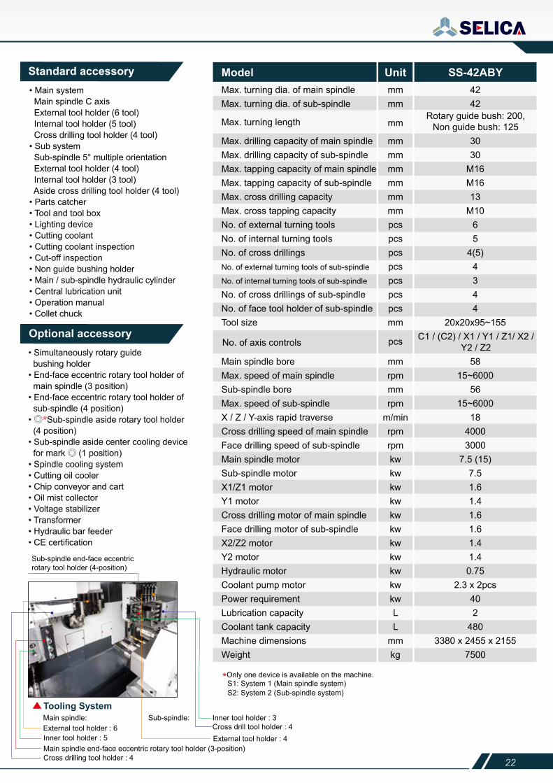
Standard accessory• Main system Main spindle C axis External tool holder (6 tool) Internal tool holder (5 tool) Cross drilling tool holder (4 tool)• Sub system Sub-spindle 5° multiple orientation External tool holder (4 tool) Internal tool holder (3 tool) Aside cross drilling tool holder (4 tool)• Parts catcher• Tool and tool box• Lighting device• Cutting coolant• Cutting coolant inspection• Cut-off inspection• Non guide bushing holder• Main / sub-spindle hydraulic cylinder• Central lubrication unit• Operation manual• Collet chuck
• Simultaneously rotary guide bushing holder• End-face eccentric rotary tool holder of main spindle (3 position)• End-face eccentric rotary tool holder of sub-spindle (4 position)• ◎*Sub-spindle aside rotary tool holder (4 position)• Sub-spindle aside center cooling device for mark ◎ (1 position) • Spindle cooling system• Cutting oil cooler• Chip conveyor and cart• Oil mist collector• Voltage stabilizer• Transformer• Hydraulic bar feeder• CE certification
Optional accessory
Sub-spindle end-face eccentric rotary tool holder (4-position)
Inner tool holder : 3
Inner tool holder : 5
Cross drilling tool holder : 4Main spindle end-face eccentric rotary tool holder (3-position)
External tool holder : 4External tool holder : 6Main spindle: Sub-spindle:Tooling System
Cross drill tool holder : 4
*Only one device is available on the machine.S1: System 1 (Main spindle system)S2: System 2 (Sub-spindle system)
Model Unit SS-42ABYMax. turning dia. of main spindleMax. turning dia. of sub-spindle
Max. turning length
No. of axis controls
mmmm
mm
pcs
4242
Max. drilling capacity of main spindleMax. drilling capacity of sub-spindleMax. tapping capacity of main spindleMax. tapping capacity of sub-spindleMax. cross drilling capacityMax. cross tapping capacityNo. of external turning toolsNo. of internal turning toolsNo. of cross drillingsNo. of external turning tools of sub-spindle
No. of internal turning tools of sub-spindle
No. of cross drillings of sub-spindleNo. of face tool holder of sub-spindleTool size
mmmmmmmmmmmmpcspcspcspcspcspcspcsmm
3030
M16M1613
M1065
4(5)4344
20x20x95~155
Main spindle boreMax. speed of main spindle Sub-spindle boreMax. speed of sub-spindle X / Z / Y-axis rapid traverseCross drilling speed of main spindleFace drilling speed of sub-spindleMain spindle motorSub-spindle motorX1/Z1 motorY1 motorCross drilling motor of main spindleFace drilling motor of sub-spindleX2/Z2 motorY2 motorHydraulic motorCoolant pump motorPower requirementLubrication capacityCoolant tank capacityMachine dimensionsWeight
mmrpmmmrpm
m/minrpmrpmkwkwkwkwkwkwkwkwkwkwkwLL
mmkg
5815~6000
5615~6000
1840003000
7.5 (15)7.51.61.41.61.61.41.4
0.752.3 x 2pcs
402
4803380 x 2455 x 2155
7500
Rotary guide bush: 200, Non guide bush: 125
C1 / (C2) / X1 / Y1 / Z1/ X2 / Y2 / Z2
21 22
CNC SWISS TYPE LATHESS-42ABY * Max. turning diameter 42mm.
* Both guide bush/ non guide bush are available for making complicated components.* With hydraulic chuck system on main spindle, it accepts poor tolerance bar to save the material cost.* Deep hole drilling on sub spindle side with central cooling system. It has both fixed and rotary type.* The tooling system has two Y-axis and C axis. In total, there are 37 tool holders and 19 of them are living tools.* Cross and face drilling function are available on main and sub spindle.* Built-in spindle with oil cooling system offers high efficiency, low noise and high accuracy environment.
Sub Spindle Aside Drilling/ Milling
Parts catcherMain spindle end-faceeccentric rotary tool holder(3-position)
* S2 aside stationary tool holder (4-position)
Main spindle end-face eccentric rotary tool holder(3-position)
Internal tool holder(5-tool)
The four tool holder next to sub spindle can be equipped either stationary or rotary toolholders. One of the four tool holders can be equipped central cooling system to make deep hole drilling.
The parts catcher is at left side of spindles and it catches the part from sub spindle.
Standard accessory• Main system Main spindle C axis External tool holder (6 tool) Internal tool holder (5 tool) Cross drilling tool holder (4 tool)• Sub system Sub-spindle 5° multiple orientation External tool holder (4 tool) Internal tool holder (3 tool) Aside cross drilling tool holder (4 tool)• Parts catcher• Tool and tool box• Lighting device• Cutting coolant• Cutting coolant inspection• Cut-off inspection• Non guide bushing holder• Main / sub-spindle hydraulic cylinder• Central lubrication unit• Operation manual• Collet chuck
• Simultaneously rotary guide bushing holder• End-face eccentric rotary tool holder of main spindle (3 position)• End-face eccentric rotary tool holder of sub-spindle (4 position)• ◎*Sub-spindle aside rotary tool holder (4 position)• Sub-spindle aside center cooling device for mark ◎ (1 position) • Spindle cooling system• Cutting oil cooler• Chip conveyor and cart• Oil mist collector• Voltage stabilizer• Transformer• Hydraulic bar feeder• CE certification
Optional accessory
Sub-spindle end-face eccentric rotary tool holder (4-position)
Inner tool holder : 3
Inner tool holder : 5
Cross drilling tool holder : 4Main spindle end-face eccentric rotary tool holder (3-position)
External tool holder : 4External tool holder : 6Main spindle: Sub-spindle:Tooling System
Cross drill tool holder : 4
*Only one device is available on the machine.S1: System 1 (Main spindle system)S2: System 2 (Sub-spindle system)
Model Unit SS-42ABYMax. turning dia. of main spindleMax. turning dia. of sub-spindle
Max. turning length
No. of axis controls
mmmm
mm
pcs
4242
Max. drilling capacity of main spindleMax. drilling capacity of sub-spindleMax. tapping capacity of main spindleMax. tapping capacity of sub-spindleMax. cross drilling capacityMax. cross tapping capacityNo. of external turning toolsNo. of internal turning toolsNo. of cross drillingsNo. of external turning tools of sub-spindle
No. of internal turning tools of sub-spindle
No. of cross drillings of sub-spindleNo. of face tool holder of sub-spindleTool size
mmmmmmmmmmmmpcspcspcspcspcspcspcsmm
3030
M16M1613
M1065
4(5)4344
20x20x95~155
Main spindle boreMax. speed of main spindle Sub-spindle boreMax. speed of sub-spindle X / Z / Y-axis rapid traverseCross drilling speed of main spindleFace drilling speed of sub-spindleMain spindle motorSub-spindle motorX1/Z1 motorY1 motorCross drilling motor of main spindleFace drilling motor of sub-spindleX2/Z2 motorY2 motorHydraulic motorCoolant pump motorPower requirementLubrication capacityCoolant tank capacityMachine dimensionsWeight
mmrpmmmrpm
m/minrpmrpmkwkwkwkwkwkwkwkwkwkwkwLL
mmkg
5815~6000
5615~6000
1840003000
7.5 (15)7.51.61.41.61.61.41.40.75
2.3 x 2pcs402
4803380 x 2455 x 2155
7500
Rotary guide bush: 200, Non guide bush: 125
C1 / (C2) / X1 / Y1 / Z1/ X2 / Y2 / Z2
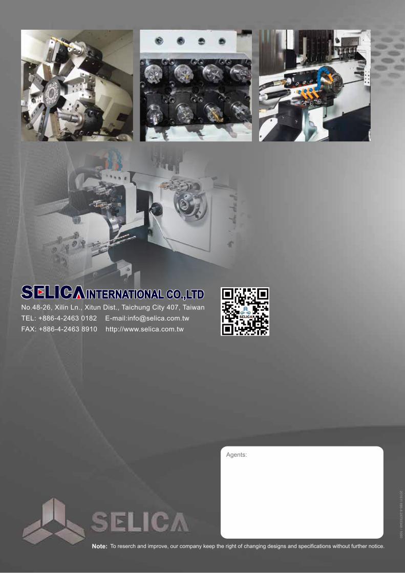
PRECISION CNC LATHECNC MULTI-TASKING TURNING CENTER
To reserch and improve, our company keep the right of changing designs and specifications without further notice.
No.48-26, Xilin Ln., Xitun Dist., Taichung City 407, TaiwanTEL: +886-4-2463 0182 E-mail:[email protected]: +886-4-2463 8910 http://www.selica.com.tw
Note:
Agents:
201611 886-4-24793348 / 1000